

Extreme Networks ExtremeSwitching VDX 6740 Hardware Installation Manual

HARDWARE INSTALLATION GUIDE
ExtremeSwitching VDX 6740
Hardware Installation Guide
9036108-00
April 2019

Copyright © 2019 Extreme Networks, Inc. All Rights Reserved.
Legal Notice
Extreme Networks, Inc. reserves the right to make changes in specications and other information contained in this document and its
website without prior notice. The reader should in all cases consult representatives of Extreme Networks to determine whether any such
changes have been made.
The hardware, rmware, software or any specications described or referred to in this document are subject to change without notice.
Trademarks
Extreme Networks and the Extreme Networks logo are trademarks or registered trademarks of Extreme Networks, Inc. in the United
States and/or other countries.
All other names (including any product names) mentioned in this document are the property of their respective owners and may be
trademarks or registered trademarks of their respective companies/owners.
For additional information on Extreme Networks trademarks, please see: www.extremenetworks.com/company/legal/trademarks
Open Source Declarations
Some software
declarations can be found at: www.extremenetworks.com/support/policies/software-licensing
les have been licensed under certain open source or third-party licenses. End-user license agreements and open source
2 9036108-00
ExtremeSwitching VDX 6740 Hardware Installation Guide

Contents
Preface...................................................................................................................................................................................................................................7
Conventions..................................................................................................................................................................................................................................................7
Notes, cautions, and warnings.....................................................................................................................................................................................................7
Text formatting conventions.........................................................................................................................................................................................................7
Command syntax conventions....................................................................................................................................................................................................8
Documentation and Training................................................................................................................................................................................................................. 8
Training.................................................................................................................................................................................................................................................. 8
Getting Help................................................................................................................................................................................................................................................. 8
Subscribing to Service Notications.........................................................................................................................................................................................9
Providing Feedback to Us......................................................................................................................................................................................................................9
About This Document..................................................................................................................................................................................................... 11
Supported hardware and software...................................................................................................................................................................................................11
What’s new in this document............................................................................................................................................................................................................. 11
Product Overview.............................................................................................................................................................................................................13
Product features.......................................................................................................................................................................................................................................13
FlexPort..............................................................................................................................................................................................................................................14
Using the VDX 6740T as a DHCP server..........................................................................................................................................................................15
Extreme Networks inter-switch link trunks..........................................................................................................................................................................16
Supported transceivers............................................................................................................................................................................................................... 17
Extreme Networks inter-switch link trunks..........................................................................................................................................................................17
Hardware components..........................................................................................................................................................................................................................18
Port side view .................................................................................................................................................................................................................................19
Nonport side view..........................................................................................................................................................................................................................20
Extreme Networks inter-switch link trunks..........................................................................................................................................................................22
Preparing for the Installation..........................................................................................................................................................................................25
Installation and safety considerations.............................................................................................................................................................................................25
Power precautions.........................................................................................................................................................................................................................25
Environmental precautions........................................................................................................................................................................................................ 26
EIA rack considerations...............................................................................................................................................................................................................26
Recommendations for cable management........................................................................................................................................................................26
Items required for the installation..................................................................................................................................................................................................... 27
Items included with the device...........................................................................................................................................................................................................27
Mounting the Device........................................................................................................................................................................................................29
Mounting options....................................................................................................................................................................................................................................29
Mounting precautions............................................................................................................................................................................................................................30
Standalone installation .........................................................................................................................................................................................................................30
Installing the 1U Slim Rail Rack Mount Kit for Four-Post Racks (XBR-000291)......................................................................................................31
Time and items required.............................................................................................................................................................................................................31
Parts List............................................................................................................................................................................................................................................31
Attaching the front brackets.......................................................................................................................................................................................................32
Installing the device in the rack................................................................................................................................................................................................ 33
Attaching the rear brackets to the front brackets..............................................................................................................................................................34
Attaching the rear brackets to the rack rails........................................................................................................................................................................35
Installing the 1U, 1.5U, and 2U Universal Kit for Four Post Racks (XBR-R000295)..............................................................................................35
ExtremeSwitching VDX 6740 Hardware Installation Guide
9036108-00 3

Time and items required...................................................................................................................................................................................................................... 36
Parts list.......................................................................................................................................................................................................................................................36
Flush-front mounting the device in the rack................................................................................................................................................................................37
Attaching the front brackets.......................................................................................................................................................................................................38
Attaching the bracket extensions to the device.................................................................................................................................................................39
Installing the device in the rack................................................................................................................................................................................................ 40
Attaching the rear brackets to the extensions....................................................................................................................................................................41
Attaching the rear brackets to the rack posts.....................................................................................................................................................................43
Flush-rear (recessed) mounting the device in the rack............................................................................................................................................................44
Attaching the front brackets to the rear of the device.....................................................................................................................................................44
Attaching the bracket extensions to the front of the device.........................................................................................................................................45
Installing the device in the rack................................................................................................................................................................................................ 46
Attaching the rear brackets to the bracket extensions at the front of the device.................................................................................................47
Attaching the rear brackets to the front rack posts..........................................................................................................................................................49
Installing the 1U, 1.5U, and 2U Mid-Mount Kit for Two-Post Racks (XBR-000165, XBR-000175, and XBR-R000292)................ 50
Time and items required.............................................................................................................................................................................................................51
Parts list............................................................................................................................................................................................................................................. 51
Attaching the front brackets to the device...........................................................................................................................................................................52
Attaching the device to a rack...................................................................................................................................................................................................53
Attaching the rear brackets to the rack..................................................................................................................................................................................54
Attaching the rear brackets to the device.............................................................................................................................................................................55
Installing the 1U and 2U Flush-Mount Rack Kit for Two-Post Racks (XBR-000307 and XBR-R000293).................................................56
Time and items required.............................................................................................................................................................................................................56
Parts list............................................................................................................................................................................................................................................. 57
Attaching the front brackets to the device...........................................................................................................................................................................58
Attaching the front brackets to the rack................................................................................................................................................................................59
Attaching the rear brackets to the rack..................................................................................................................................................................................59
Attaching the rear brackets to the device.............................................................................................................................................................................60
Installing the Universal Four-Post Rack Kit (XBR-R000296).............................................................................................................................................61
Time and items required.............................................................................................................................................................................................................62
Parts list............................................................................................................................................................................................................................................. 62
Flush-front mounting...................................................................................................................................................................................................................64
Flush-rear (recessed) mounting...............................................................................................................................................................................................69
Installing the Universal Two-Post Rack Kit (XBR-R000294)..............................................................................................................................................74
Time and items required.............................................................................................................................................................................................................75
Parts list............................................................................................................................................................................................................................................. 75
Flush-front mounting...................................................................................................................................................................................................................76
Mid-mounting.................................................................................................................................................................................................................................80
Initial Conguration..........................................................................................................................................................................................................85
Conguration overview......................................................................................................................................................................................................................... 85
Items required...........................................................................................................................................................................................................................................86
Providing power to the device........................................................................................................................................................................................................... 86
Connecting an AC power cord................................................................................................................................................................................................. 86
Connecting a power cord to a 500W DC power supply...............................................................................................................................................87
Connecting a DC power cord to a 250W DC power supply.......................................................................................................................................88
Verifying operation..................................................................................................................................................................................................................................89
Establishing a serial connection........................................................................................................................................................................................................89
Assigning permanent passwords ....................................................................................................................................................................................................90
Changing the default account passwords .......................................................................................................................................................................... 90
Conguring the device IP address...................................................................................................................................................................................................91
4 9036108-00
ExtremeSwitching VDX 6740 Hardware Installation Guide

Using DHCP to set the IP address.........................................................................................................................................................................................91
Setting a static IP address..........................................................................................................................................................................................................91
Stateless IPv6 autoconguration............................................................................................................................................................................................92
Setting stateless IPv6 autoconguration.............................................................................................................................................................................92
Setting the date and time ....................................................................................................................................................................................................................93
Time zones.......................................................................................................................................................................................................................................93
Time synchronization...................................................................................................................................................................................................................93
Synchronizing local time using NTP......................................................................................................................................................................................93
Setting the clock (date and time) manually..........................................................................................................................................................................94
Setting the time zone................................................................................................................................................................................................................... 94
Changing the RBridge ID and VCS ID...........................................................................................................................................................................................95
Network device connections..............................................................................................................................................................................................................95
Ethernet or Fast Ethernet hubs................................................................................................................................................................................................95
Workstations, servers, or routers.............................................................................................................................................................................................95
Network device...............................................................................................................................................................................................................................95
Testing connectivity...................................................................................................................................................................................................................... 96
Upgrading port speeds on the VDX 6740T...............................................................................................................................................................................96
Operation and Maintenance...........................................................................................................................................................................................99
LED activity interpretation...................................................................................................................................................................................................................99
LEDs................................................................................................................................................................................................................................................... 99
LED locations..................................................................................................................................................................................................................................99
LED patterns.................................................................................................................................................................................................................................101
POST and boot specications........................................................................................................................................................................................................104
POST...............................................................................................................................................................................................................................................104
Boot..................................................................................................................................................................................................................................................104
Interpreting POST results.................................................................................................................................................................................................................104
Powering o the device.....................................................................................................................................................................................................................105
Thermal operations.............................................................................................................................................................................................................................105
Device maintenance............................................................................................................................................................................................................................105
Installing an Ethernet SFP+ transceiver.............................................................................................................................................................................105
Installing a FC SFP+..................................................................................................................................................................................................................106
Diagnostic tests...........................................................................................................................................................................................................................107
Upgrading rmware...................................................................................................................................................................................................................108
Device management.......................................................................................................................................................................................................................... 108
Removal and Replacement Procedures....................................................................................................................................................................109
Before beginning replacement ......................................................................................................................................................................................................109
FRU replacement in a VDX 6740................................................................................................................................................................................................110
Determining the need to replace an assembly...............................................................................................................................................................111
Time and items required..........................................................................................................................................................................................................111
Replacing the power supply and fan assembly..............................................................................................................................................................111
FRU replacement in the VDX 6740T.........................................................................................................................................................................................112
Determining the need to replace a power supply..........................................................................................................................................................113
Time and items required to replace a power supply.................................................................................................................................................... 113
Replacing a 500W AC power supply.................................................................................................................................................................................113
Determining the need to replace a fan assembly..........................................................................................................................................................115
Time and items required to replace a fan assembly....................................................................................................................................................115
Replacing a fan assembly....................................................................................................................................................................................................... 115
Technical Specications............................................................................................................................................................................................... 117
ExtremeSwitching VDX 6740 Switch Technical Specications.......................................................................................................................................117
ExtremeSwitching VDX 6740 Hardware Installation Guide
9036108-00 5

System specications...............................................................................................................................................................................................................117
Ethernet...........................................................................................................................................................................................................................................117
LEDs................................................................................................................................................................................................................................................ 117
Other................................................................................................................................................................................................................................................118
Weight and physical dimensions..........................................................................................................................................................................................118
Environmental requirements..................................................................................................................................................................................................118
Power supply specications (per PSU)..............................................................................................................................................................................119
Power consumption VDX 6740 and VDX 6740T (idle conguration)............................................................................................................... 119
Power consumption VDX 6740 (typical conguration)..............................................................................................................................................120
Power consumption VDX 6740T (typical conguration)...........................................................................................................................................120
Power consumption VDX 6740 and 6740T (maximum conguration)............................................................................................................ 121
Data port specications (Ethernet).......................................................................................................................................................................................121
Serial port specications (pinout mini-USB)...................................................................................................................................................................121
Serial port specications (pinout RJ-45).......................................................................................................................................................................... 122
Serial port specications (protocol).....................................................................................................................................................................................122
Memory specications............................................................................................................................................................................................................. 122
Regulatory compliance (EMC)...............................................................................................................................................................................................122
Regulatory compliance (safety).............................................................................................................................................................................................123
Regulatory compliance (environmental)............................................................................................................................................................................123
Regulatory Statements.................................................................................................................................................................................................125
BSMI statement (Taiwan).................................................................................................................................................................................................................. 125
Canadian requirements......................................................................................................................................................................................................................125
CE statement.........................................................................................................................................................................................................................................125
China ROHS.......................................................................................................................................................................................................................................... 126
Federal Communications Commission (FCC) Notice.......................................................................................................................................................... 126
Germany statement.............................................................................................................................................................................................................................126
KCC statement (Republic of Korea)..............................................................................................................................................................................................126
Japan (VCCI Class A)..........................................................................................................................................................................................................................127
Japan power cord ................................................................................................................................................................................................................................127
Cautions and Danger Notices..................................................................................................................................................................................... 129
Cautions...................................................................................................................................................................................................................................................129
General cautions......................................................................................................................................................................................................................... 129
Electrical cautions.......................................................................................................................................................................................................................131
Danger Notices.....................................................................................................................................................................................................................................133
General dangers..........................................................................................................................................................................................................................134
Electrical dangers........................................................................................................................................................................................................................134
Dangers related to equipment weight................................................................................................................................................................................134
Laser dangers.............................................................................................................................................................................................................................. 135
6 9036108-00
ExtremeSwitching VDX 6740 Hardware Installation Guide

Preface
• Conventions............................................................................................................................................................................................................7
• Documentation and Training............................................................................................................................................................................8
• Getting Help............................................................................................................................................................................................................8
• Providing Feedback to Us.................................................................................................................................................................................9
This section discusses the conventions used in this guide, ways to provide feedback, additional help, and other Extreme Networks
publications.
Conventions
This section discusses the conventions used in this guide.
Notes, cautions, and warnings
Notes, cautions, and warning statements may be used in this document. They are listed in the order of increasing severity of potential
hazards.
NOTE
A Note provides a tip, guidance, or advice, emphasizes important information, or provides a reference to related information.
ATTENTION
An Attention statement indicates a stronger note, for example, to alert you when trac might be interrupted or the device might
reboot.
®
CAUTION
A Caution statement alerts you to situations that can be potentially hazardous to you or cause damage to hardware,
rmware, software, or data.
DANGER
A Danger statement indicates conditions or situations that can be potentially lethal or extremely hazardous to you. Safety
labels are also attached directly to products to warn of these conditions or situations.
Text formatting conventions
Text formatting conventions such as boldface, italic, or Courier font may be used to highlight specic words or phrases.
Format Description
bold text Identies command names.
Identies keywords and operands.
Identies the names of GUI elements.
Identies text to enter in the GUI.
italic text Identies emphasis.
Identies variables.
Identies document titles.
ExtremeSwitching VDX 6740 Hardware Installation Guide
9036108-00 7

Documentation and Training
Format Description
Courier font
Identies CLI output.
Identies command syntax examples.
Command syntax conventions
Bold and italic text identify command syntax components. Delimiters and operators
relationships.
Convention Description
bold text Identies command names, keywords, and command options.
italic text Identies a variable.
[ ] Syntax components displayed within square brackets are optional.
Default responses to system prompts are enclosed in square brackets.
{ x | y | z } A choice of required parameters is enclosed in curly brackets separated by vertical bars. You must select
one of the options.
x | y A vertical bar separates mutually exclusive elements.
< > Nonprinting characters, for example, passwords, are enclosed in angle brackets.
... Repeat the previous element, for example, member[member...].
\ Indicates a “soft” line break in command examples. If a backslash separates two lines of a command
input, enter the entire command at the prompt without the backslash.
dene groupings of parameters and their logical
Documentation and Training
To nd Extreme Networks product guides, visit our documentation pages at:
Current Product Documentation www.extremenetworks.com/documentation/
Archived Documentation (for earlier versions and
legacy products)
Release Notes www.extremenetworks.com/support/release-notes
Hardware/Software Compatibility Matrices https://www.extremenetworks.com/support/compatibility-matrices/
White papers, data sheets, case studies, and other
product resources
www.extremenetworks.com/support/documentation-archives/
https://www.extremenetworks.com/resources/
Training
Extreme Networks
visit www.extremenetworks.com/education/.
oers product training courses, both online and in person, as well as specialized certications. For more information,
Getting Help
If you require assistance, contact Extreme Networks using one of the following methods:
8 9036108-00
ExtremeSwitching VDX 6740 Hardware Installation Guide

Providing Feedback to Us
Extreme Portal Search the GTAC (Global Technical Assistance Center) knowledge base, manage support cases and service
contracts, download software, and obtain product licensing, training, and certications.
The Hub A forum for Extreme Networks customers to connect with one another, answer questions, and share ideas and
feedback. This community is monitored by Extreme Networks employees, but is not intended to replace specic
guidance from GTAC.
Call GTAC For immediate support: 1-800-998-2408 (toll-free in U.S. and Canada) or +1 408-579-2826. For the support
phone number in your country, visit: www.extremenetworks.com/support/contact
Before contacting Extreme Networks for technical support, have the following information ready:
• Your Extreme Networks service contract number and/or serial numbers for all involved Extreme Networks products
• A description of the failure
• A description of any action(s) already taken to resolve the problem
• A description of your network environment (such as layout, cable type, other relevant environmental information)
• Network load at the time of trouble (if known)
• The device history (for example, if you have returned the device before, or if this is a recurring problem)
• Any related RMA (Return Material Authorization) numbers
Subscribing to Service Notications
You can subscribe to email notications for product and software release announcements, Vulnerability Notices, and Service
Notications.
1. Go to www.extremenetworks.com/support/service-notication-form.
2. Complete the form with your information (all elds are required).
3. Select the products for which you would like to receive notications.
NOTE
You can modify your product selections or unsubscribe at any time.
4. Click Submit.
Providing Feedback to Us
Quality is our
document. We are always striving to improve our documentation and help you work better, so we want to hear from you! We welcome all
feedback but especially want to know about:
• Content errors or confusing or conicting information.
• Ideas for improvements to our documentation so you can nd the information you need faster.
• Broken links or usability issues.
rst concern at Extreme Networks, and we have made every eort to ensure the accuracy and completeness of this
If you would like to provide feedback to the Extreme Networks Information Development team, you can do so in two ways:
• Use our short online feedback form at https://www.extremenetworks.com/documentation-feedback/.
• Email us at documentation@extremenetworks.com.
Please provide the publication title, part number, and as much detail as possible, including the topic heading and page number if
applicable, as well as your suggestions for improvement.
ExtremeSwitching VDX 6740 Hardware Installation Guide
9036108-00 9

10 9036108-00
ExtremeSwitching VDX 6740 Hardware Installation Guide

About This Document
• Supported hardware and software..............................................................................................................................................................11
• What’s new in this document........................................................................................................................................................................11
Supported hardware and software
This document includes information specic to the ExtremeSwitching VDX 6740 and ExtremeSwitching VDX 6740T running Extreme
Network OS version 7.1.0 and later.
The VDX 6740T information in this guide also covers the VDX 6740T-1G variant running Extreme Network OS version 7.1.0 and later.
The VDX 6740 and VDX 6740T were rst supported at Network OS 4.0.0.
What’s new in this document
This is a new document.
NOTE
Fibre Channel (FC) is no longer supported. However, instances of "FC" and "FCoE" (Fibre Channel over Ethernet) may still
appear in CLI "show" outputs and elsewhere.
ExtremeSwitching VDX 6740 Hardware Installation Guide
9036108-00 11

12 9036108-00
ExtremeSwitching VDX 6740 Hardware Installation Guide

Product Overview
• Product features.................................................................................................................................................................................................13
• Hardware components....................................................................................................................................................................................18
Product features
The ExtremeSwitching VDX 6740 product family includes three top-of-rack, Gigabit Ethernet (GbE) line-rate, low latency, lossless Data
Center Bridging (DCB) devices:
The VDX 6740 has the following features:
• Base models support 24 Ethernet ports. A 10G Port Upgrade license can add ports in increments of 8, 16, and 24 ports, for a
total of 48 Ethernet ports. The following types of optics can be installed in these ports:
– 1/10 GbE ports operating at 1 Gbps, 10 Gbps, or in auto-sensing mode (1 or 10 Gbps).
– 1 GbE copper optics, operating at 1 Gbps and 100 Mbps.
– 8 Gbps Fibre channel optics operating at 2, 4, and 8 Gbps and 16 Gbps optics operating at 4, 8, and 16 Gbps when the
FlexPort feature is used.
• Base models do not support 40 GbE ports, but a 40G Port Upgrade license can add two or four 40 GbE ports. Only 4x10
GbE QSFP+ optics can be installed in these ports as FlexPort is not supported on the 40 GbE ports.
The VDX 6740T has the following features:
• Base models support 24 Ethernet ports. A 10G Port Upgrade license can add ports in increments of 8, 16, and 24 ports, for a
total of 48 Ethernet ports. These ports support Base-T (RJ-45) transceivers operating at 100 Mbps, 1 Gbps, 10 Gbps, or in
auto-sensing mode.
• Base models do not contain 40 GbE ports, but a 40G Port Upgrade license can add two or four 40 GbE ports. These ports
support the following optics:
– 40 GbE optics
– 4x10 GbE QSFP+ optics.
– 4x16 Fibre Channel QSFP+ optics if the FlexPort feature is used. Fibre Channel operation is supported on 40-GbE ports
congured in SFP breakout mode (also referred to as 4x10 GbE breakout mode) that use qualied 4x16 Fibre Channel
QSFP+ optics.
The VDX 6740T-1G variant has the following features:
• Base models are fully populated with 48 Ethernet ports. These ports support Base-T (RJ-45) transceivers operating at 100
Mbps, 1 Gbps, or in auto-sensing mode. A 10G Port Upgrade license enables port operation at 100 Mbps, 1 Gbps, 10 Gbps,
or in auto-sensing mode. This upgrade can be installed in increments of 16, 32, and 48 ports.
• Base models contain two 40 GbE ports. A 40G Port Upgrade license can be added for two additional 40 GbE ports. These
ports support the following optics:
– 40 GbE optics
– 4x10 GbE QSFP+ optics.
– 4x16 Fibre Channel QSFP+ optics if the FlexPort feature is used. Fibre Channel operation is supported on 40-GbE ports
congured in 40 GbE mode that use qualied 4x16 Fibre Channel QSFP+ optics.
For all models, the 40 GbE port can be recongured as four 10 GbE ports in SFP breakout mode (also referred to as 4x10 GbE
breakout mode). Thus, the device can be congured with as many as 64 10 GbE ports. For instructions on conguring breakout mode,
refer to the "SFP breakout" section of the Extreme Network OS Management Conguration Guide.
ExtremeSwitching VDX 6740 Hardware Installation Guide
9036108-00 13

Product features
The VDX 6740 devices run on the Extreme Network OS v4.0.0 or later. The 100 Mbps speed for Base-T ports on the VDX 6740T is
available with Extreme Network OS v4.1.0 and later. For details about Extreme Network OS, refer to the Extreme Network OS
Management Conguration Guide.
A key feature of this device is ExtremeSwitching VCS™ technology, which includes virtual cluster switching, a set of technologies that
allows users to create atter, virtualize, and converged data center networks. VCS fabrics are scalable, permitting users to expand at their
own pace, and simplied, allowing users to manage the fabric as a single entity. VCS-based Ethernet fabrics are convergence-capable
with technologies such as Fibre Channel over Ethernet (FCoE) for storage.
This device can also be deployed in IP fabrics. An IP fabric can be described as a collection of discrete Layer 3 elements (such as switchrouters) arranged in a spine-leaf network. These elements exchange Layer 2 and Layer 3 database information to provide a exible, non-
blocking and scalable framework while retaining the semantics of a single logical switch. There can be competing protocols for
exchanging this distributed database across such discrete elements. Spine-leaf networks are designed to be a three-stage architecture,
an ingress stage, a middle stage, and an egress stage. The concept is that there are multiple paths for the call to be switched through the
network so that trac can always connect and not be blocked. For full details and conguration procedures for IP fabrics, refer to the
Extreme Network OS IP Fabrics Conguration Guide.
FlexPort
The FlexPort feature is supported on the VDX 6740 with Network OS 5.0.0 and later and on the VDX 6740T with Network OS 6.0.0
and later. This feature allows you to attach a FC device to run encapsulated FC over Ethernet (FCOE)
trac through the device.
To congure FlexPort and Fibre Channel operation for specic VDX 6740 ports, follow steps in the "FlexPort" section of the Network OS
Management Conguration Guide.
FlexPort allows you to congure specic groups of ports, called connector groups, as 10 Gbps Ethernet ports or as Fibre Channel (FC)
ports. Up to 32 ports can be congured as FlexPorts. These ports can be changed from Ethernet to Fibre Channel operation without a
reboot. Qualied 10 GbE SFP+ transceivers or 4x10 GbE breakout cables must be installed to allow Ethernet operation. Qualied 8
Gbps FC, 16 Gbps FC, or 4x16G QSFP+ transceivers must be installed to allow Fibre Channel operation.
Connector groups share common speed and protocol type properties. You can congure the following speed and protocol combinations
in each connector group:
• LowMixed - 2, 4, and 8 Gbps FC and 1/10 Gbps Ethernet
• HighMixed - 16 Gbps FC and 10 Gbps Ethernet only
• FibreChannel - 2, 4, 8, and 16 Gbps FC (no Ethernet)
For the VDX 6740T, Ethernet operation is supported on 40 GbE QSFP ports congured in 40 GbE mode that use qualied 40 GbE
transceivers and on 40 GbE ports in SFP breakout mode (also referred to as 4x10 GbE breakout mode) that use qualied 4x10 GbE
QSFP transceivers. Fibre Channel operation is supported on 40 GbE ports congured in SFP breakout mode that use qualied 4x16
QSFP+ transceivers. FlexPort is not supported on 40 GbE QSFP ports on the VDX 6740.
The default port FlexPort setting is Ethernet. Consider the following for Fibre Channel operation and ISL connections:
• Ports that do not support the Fibre Channel protocol are not allowed to have their connector group setting changed from the
default setting.
• When the system is booted up, by default, a FlexPort can become an ISL port because it is an Ethernet port in no-shut state.
However, if the FlexPort is congured as FC port, it won't become an ISL port.
For details on the FlexPort feature, including port ranges on VDX 6740 models that can be congured as FlexPorts, connector groups,
and conguration procedures, refer to the Network OS Management Conguration Guide.
14 9036108-00
ExtremeSwitching VDX 6740 Hardware Installation Guide
Product features
Using the VDX 6740T as a DHCP server
You can connect the VDX 6740T to the management port on any Extreme Networks switch (DHCP client) and use the VDX 6740T as a
DHCP server to support DHCP Automatic Deployment (DAD), DHCP zero touch provisioning (ZTP), obtaining switch IP addresses, and
other services.
The following steps provide an example for connecting a VDX 6740T as a DHCP server to a VDX 6740 functioning as the DHCP client.
• Connect the VDX 6740T Ethernet management port to any of the VDX 6740T inband 10 GbE BaseT ports using a CAT5
cable.
• Connect the VDX 6740 Ethernet management port to any of the 10 GbE ports on the VDX 6740T using a CAT5 cable.
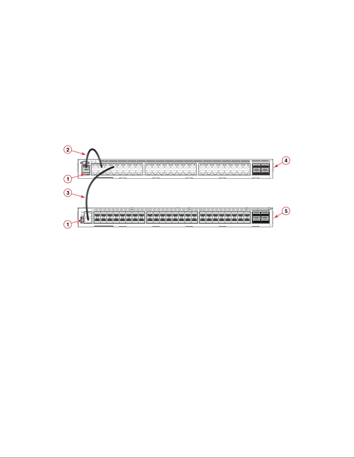
FIGURE 1 Connecting VDX 6740T as DHCP server to VDX 6740
1. Ethernet management port (RJ45)
2. CAT5 cable from management port to an VDX 6740T inband port
3. CAT5 cable from VDX 6740T inband port to VDX 6740 Ethernet
management port
4. VDX 6740T
5. VDX 6740
Following are general steps to congure the VDX 6740T as a DHCP server. For detailed procedures and Fabric OS commands, refer to
the Extreme Network OS Management Conguration Guide.
• Set up the DHCP pool address and other parameters in the dhcp.conf le.
• Congure a static IP address for the management port (DHCP must be disabled), then enable DHCP on the port.
• Congure the VDX 6740T inband ports that you are using for DHCP server connections into a VLAN so that the client
switches can obtain DHCP IP addresses from the server.
• Download the dhcpd.conf le to the VDX 6740T. A valid dhcpd.conf le must be copied into the device before enabling the
DHCP server.
Following are requirements and considerations for this feature:
• VDX 6740T is supported as the DHCP server and connected Extreme Networks switch is supported as a DHCP client.
• DHCP server must run as a standalone switch; it cannot be enabled when the switch is part of a VCS cluster.
• DHCPv6 is not supported.
• DHCP server can support up to 20 clients.
• DHCP server is not supported on inband ports without IP loopback and DHCP server support on the management port.
• DHCP conguration with a multiple subnet is not supported.
• DHCP only runs on the active CP. HA failover is supported.
ExtremeSwitching VDX 6740 Hardware Installation Guide
9036108-00 15
Product features
• "DHCP relay" must be disabled since the DHCP server uses the same port number. Enabling and disabling DHCP
automatically toggles "dhcp relay" and forces a switch reboot.
Extreme Networks inter-switch link trunks
In VCS mode, unless specically disabled, inter-switch link (ISL) Extreme Networks trunking between adjacent devices is automatic. All
ports must be in the same port group and must be congured at the same speed. There is a limit of sixteen ports per trunk group. No
separate licensing is required. Refer to the illustrations below for the exact port groups. On the VDX 6740T, ports in groups 3 and 3A, as
well as port groups 4 and 4A, cannot be trunked together. However, these ports can be trunked on the VDX 6740 when the 40 GbE
QSFP ports are congured in breakout mode. VDX 6740T 1GbE ports cannot be trunked.
NOTE
If connections are made to 16 dierent switches, only eight ports will be trunk ports while the other eight ports will be normal
ISL ports.
For instructions on conguring breakout mode and Extreme Networks trunking, refer to the Extreme Network OS Management
Conguration Guide.
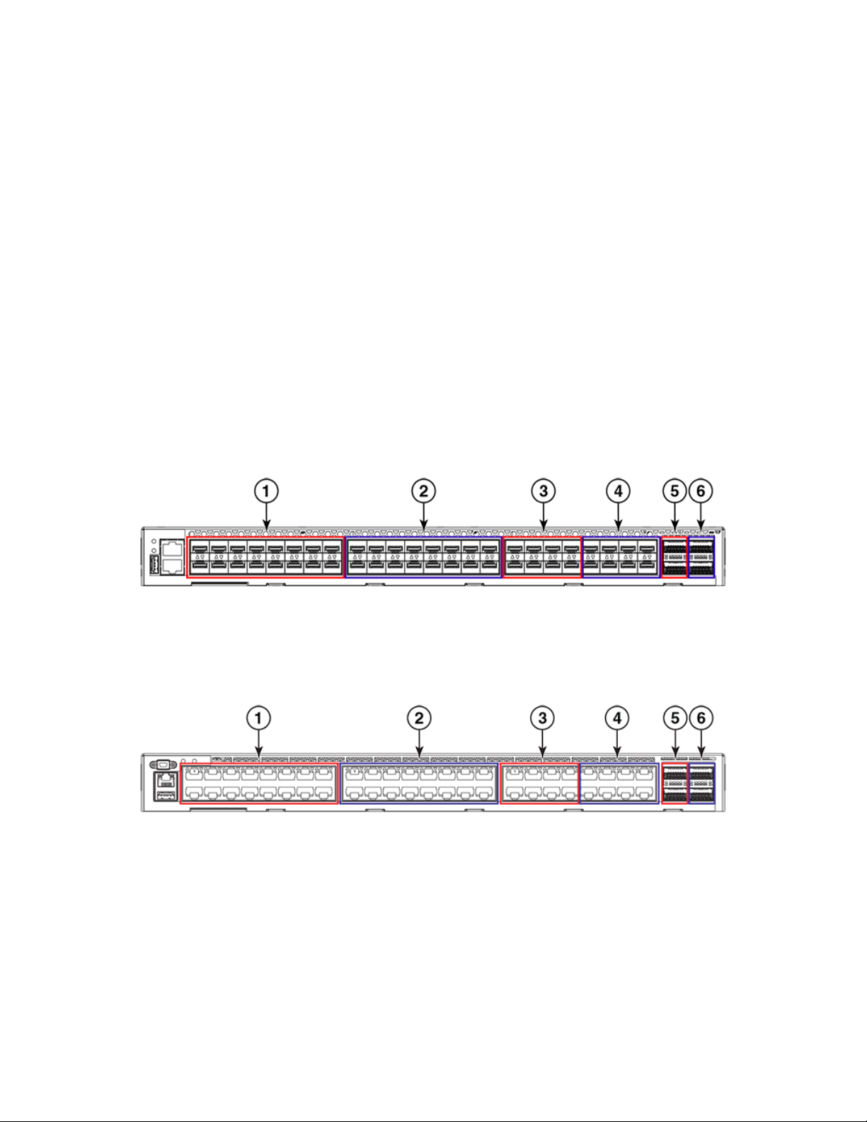
FIGURE 2 Port groups of the VDX 6740
1. Trunk Group 1 - 1/10 GbE SFP ports 1-16
2. Trunk Group 2 - 1/10 GbE SFP ports 17-32
3. Trunk Group 3 - 1/10 GbE SFP ports 33-40
FIGURE 3 Port groups of the VDX 6740T
1. Trunk Group 1 - 1/10 GbE BaseT ports 1-16
2. Trunk Group 2 - 1/10 GbE BaseT ports 17-32
3. Trunk Group 3 - 1/10 GbE BaseT ports 33-40
NOTE
For the VDX 6740T-1G variant, if you release Dynamic Ports On Demand (DPOD) licenses from any 10GbE ports on a 16port trunk congured with static 10G speed, reserve back those licenses, then perform the shutdown and no shutdown
commands on all trunk ports, the trunk bandwidth will not restore to the maximum 160 Gbps.
4. Trunk group 4 - 1/10 GbE SFP ports 41-48
5. Trunk Group 3A - 40 GbE QSFP ports 49-50
6. Trunk Group 4A - 40 GbE QSFP ports 51-52
4. Trunk Group 4 - 1/10 GbE BaseT ports 41-48
5. Trunk Group 3A - 40 GbE QSFP ports 49-50
6. Trunk Group 4A - 40 GbE QSFP ports 51-52
16 9036108-00
ExtremeSwitching VDX 6740 Hardware Installation Guide

Product features
Supported transceivers
The VDX 6740 provides up to 48 ports that support 1, 8, or 10 GbE optical SFP+ Extreme-branded Ethernet SFP+ optical or copper
transceivers. These ports also support SFP+ direct-attached Twinax copper and active and passive optical cables.
VDX 6740 ports also support 10 GbE tunable SFP+ (TSFP+) transceivers. If used, TSFP+ transceivers must be installed in the port at
each end of a link and "tuned" to the same wavelength. If not, the link may come online, but operation may be unpredictable. If
wavelength dierence exceeds a specied limit, a RASLOG message occurs and the port is taken oine. You can congure wavelengths
for installed transceivers using channel numbers from 1 to 102 that correspond to wavelengths from 1568.77 to 1528.38 nm using
the tunable-optics sfpp channel channel number command. For details on using this and related commands, refer to the "Tunable SFP+
optics" section of the Extreme Network OS Management Conguration Guide.
The VDX 6740T provides 48 ports with 10G Base-T RJ-45 connectors for copper twisted-pair only.
Both the VDX 6740 and VDX 6740T provide four ports that support 40 GbE QSFP+ transceivers. These ports support SFP breakout
mode (also referred to 4x10 GbE breakout mode) using 4x10 GbE breakout cables. Fibre Channel FlexPort operation is supported only
when ports are in 40 GbE mode using optical 4x16G QSFP+ short wavelength transceivers. On the VDX 6740T, the 40 GbE ports also
support 10 GbE SFP+ transceivers when the QSA Adapter is used.
For details on supported transceivers for all VDX 6940 models, refer to the ExtremeSwitching VDX Transceiver Support Matrix. Access
this matrix on the www.extremenetworks.com website by selecting Product and Services from the menu, scroll down Transceivers, and
then select Transceiver Modules. Also contact your Extreme Networks representative for current transceiver support and ordering
information.
• ExtremeSwitching VDX Transceiver Support Matrix
• Extreme Fibre Channel Transceiver Support Matrix
DANGER
All ber-optic interfaces use Class 1 lasers.
DANGER
Laser Radiation. Do Not View Directly with Optical Instruments. Class 1M Laser Products.
Extreme Networks inter-switch link trunks
In VCS mode, unless specically disabled, inter-switch link (ISL) Extreme Networks trunking between adjacent devices is automatic. All
ports must be in the same port group and must be congured at the same speed. There is a limit of sixteen ports per trunk group. No
separate licensing is required. Refer to the illustrations below for the exact port groups. On the VDX 6740T, ports in groups 3 and 3A, as
well as port groups 4 and 4A, cannot be trunked together. However, these ports can be trunked on the VDX 6740 when the 40 GbE
QSFP ports are congured in breakout mode. VDX 6740T 1GbE ports cannot be trunked.
NOTE
If connections are made to 16 dierent switches, only eight ports will be trunk ports while the other eight ports will be normal
ISL ports.
For instructions on conguring breakout mode and Extreme Networks trunking, refer to the Extreme Network OS Management
Conguration Guide.
ExtremeSwitching VDX 6740 Hardware Installation Guide
9036108-00 17

Hardware components
FIGURE 4 Port groups of the VDX 6740
1. Trunk Group 1 - 1/10 GbE SFP ports 1-16
2. Trunk Group 2 - 1/10 GbE SFP ports 17-32
3. Trunk Group 3 - 1/10 GbE SFP ports 33-40
FIGURE 5 Port groups of the VDX 6740T
1. Trunk Group 1 - 1/10 GbE BaseT ports 1-16
2. Trunk Group 2 - 1/10 GbE BaseT ports 17-32
3. Trunk Group 3 - 1/10 GbE BaseT ports 33-40
NOTE
For the VDX 6740T-1G variant, if you release Dynamic Ports On Demand (DPOD) licenses from any 10GbE ports on a 16port trunk congured with static 10G speed, reserve back those licenses, then perform the shutdown and no shutdown
commands on all trunk ports, the trunk bandwidth will not restore to the maximum 160 Gbps.
4. Trunk group 4 - 1/10 GbE SFP ports 41-48
5. Trunk Group 3A - 40 GbE QSFP ports 49-50
6. Trunk Group 4A - 40 GbE QSFP ports 51-52
4. Trunk Group 4 - 1/10 GbE BaseT ports 41-48
5. Trunk Group 3A - 40 GbE QSFP ports 49-50
6. Trunk Group 4A - 40 GbE QSFP ports 51-52
Hardware components
VDX 6740 devices oer the following features and capabilities:
• The VDX 6740 has these features:
– Up to 48 1/10 GbE optical SFP+ ports.
– Up to four 40 GbE QSFP ports, each of which can be congured into four 10 GbE ports in SFP breakout mode (also
referred to as 4x10 GbE breakout mode). These ports support optical or twinaxial breakout cable when ports are
congured in SFP breakout mode.
– Dual, hot-swappable 250W AC power supplies with three integrated cooling fans each. Power supplies and fans can be
ordered with front-to-back or back-to-front airow).
– Four temperature sensors.
– A reduced-depth, rack-mount design using existing rail kits - four-post xed or Telco ush and mid-mount rack mount kits.
• The VDX 6740T has these features:
– Up to 48 1/10G Base-T copper ports. These ports support 100 Mbps operation (Network OS v4.1.0 and later). Note that
forty-eight 1G Base-T copper ports are supported on the VDX 6740T-1G variant, which can be upgraded to 1/10G
operation through 10G Port Upgrade licensing.
18 9036108-00
ExtremeSwitching VDX 6740 Hardware Installation Guide

Hardware components
– Up to four 40 GbE QSFP ports, each of which can be congured into four 10 GbE ports in SFP breakout mode (also
referred to as 4x10 GbE breakout mode). These ports support optical or twinaxial breakout cable when ports are
congured in SFP breakout mode.
– A mini-USB-fronted serial (RS-232) port for terminal access and debugging.
– Dual, hot-swappable 500W AC power supplies and ve separate, hot-swappable fan units. Power supplies and fans can be
ordered with front-to-back or back-to-front airow).
– Two temperature sensors.
– Universal 4-post and 2-post rack mount kits.
• The VDX 6740 and VDX 6740T have the following features:
– A system motherboard that features a Reduced Instruction Set Computer (RISC) CPU running at 1.5 GHz with integrated
peripherals
– An RJ-45 Ethernet out-of-band management port
– An RJ-45-fronted serial (RS-232) port for terminal access and debugging
– A USB port for rmware upgrades and system log downloads
– Support for inter-switch link (ISL) Extreme Networks Trunking (10, 40, and 100 GbE ports only)
– Extensive diagnostics and system-monitoring capabilities for enhanced high Reliability, Availability, and Serviceability (RAS)
– Optimized airow (a choice of front-to-back or back-to-front ow)
– A real-time clock (RTC) with battery
– SEEPROM for device identication
– Voltage monitoring
– Fan monitoring
– I2C interface to monitor and control environmental aspects
NOTE
Port numbering for the VDX 6740 begins with 1, not 0.
NOTE
To upgrade 1 Gbps port speed to 10 Gbps on the VDX 6740T-1G variant when installing the 10G Port Upgrade License,
refer to Upgrading port speeds on the VDX 6740T on page 96.
DANGER
Batteries used for RTC/NVRAM backup are not located in operator-access areas. There is a risk of explosion if a battery
is replace by an incorrect type. Dispose of used components containing batteries according to the local ordinance and
regulations.
Port side view
The port side of the VDX 6740 includes the system LEDs, management ports and LEDs, USB port, SFP+ ports, and the corresponding
port status LEDs.
The following illustration shows the port side of the VDX 6740.
ExtremeSwitching VDX 6740 Hardware Installation Guide
9036108-00 19
Hardware components
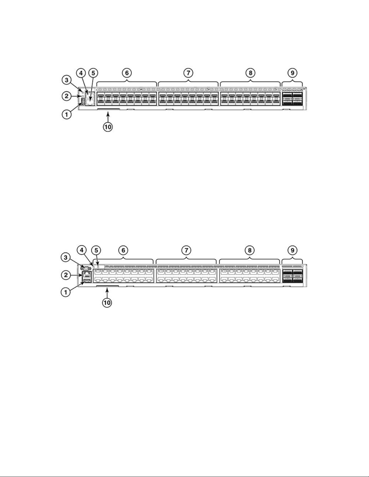
FIGURE 6 Port-side view of the VDX 6740
1. USB port
2. System power LED
3. System status LED
4. Serial console management port (RJ-45)
5. Ethernet port (RJ-45)
6. SFP+ ports 1 through 16 with status LEDs above*
7. SFP+ ports 17 through 32 with status LEDs above*
8. SFP+ ports 33 through 48 with status LEDs above*
9. 40 GbE QSFP ports 49 through 52
10. Device ID pull-out tab
*The FlexPort feature allows conguration of specic VDX 6740 ports as 1/10 GbE or 4, 8, or 16 Gbps FC ports.
The port side of the VDX 6740T includes the system LEDs, management ports and LEDs, USB port, and Base-T Ethernet ports and
the corresponding port status LEDs.
The following illustration shows the port side of the VDX 6740T.
FIGURE 7 Port-side view of the VDX 6740T
1. USB port
2. Ethernet management port (RJ45)
3. Serial console port (mini-USB)
4. System status LED
5. System power LED
6. 10 GbE BaseT ports 1 through 16 with status LEDs above*
7. 10 GbE BaseT ports 17 through 32 with status LEDs above*
8. 10 GbE BaseT ports 33 through 48 with status LEDs above*
9. 40 GbE QSFP ports 49 through 52**
10. Device ID pull-out tab
*Base ports on the VDX 6740T-1G variant operate at 1 Gbps and require Port Upgrade license to operate at 10 Gbps.
**FlexPort allows conguration of specic VDX 6740T 40 GbE QSFP+ ports as 1/10 GbE or 4, 8, or 16 Gbps FC ports.
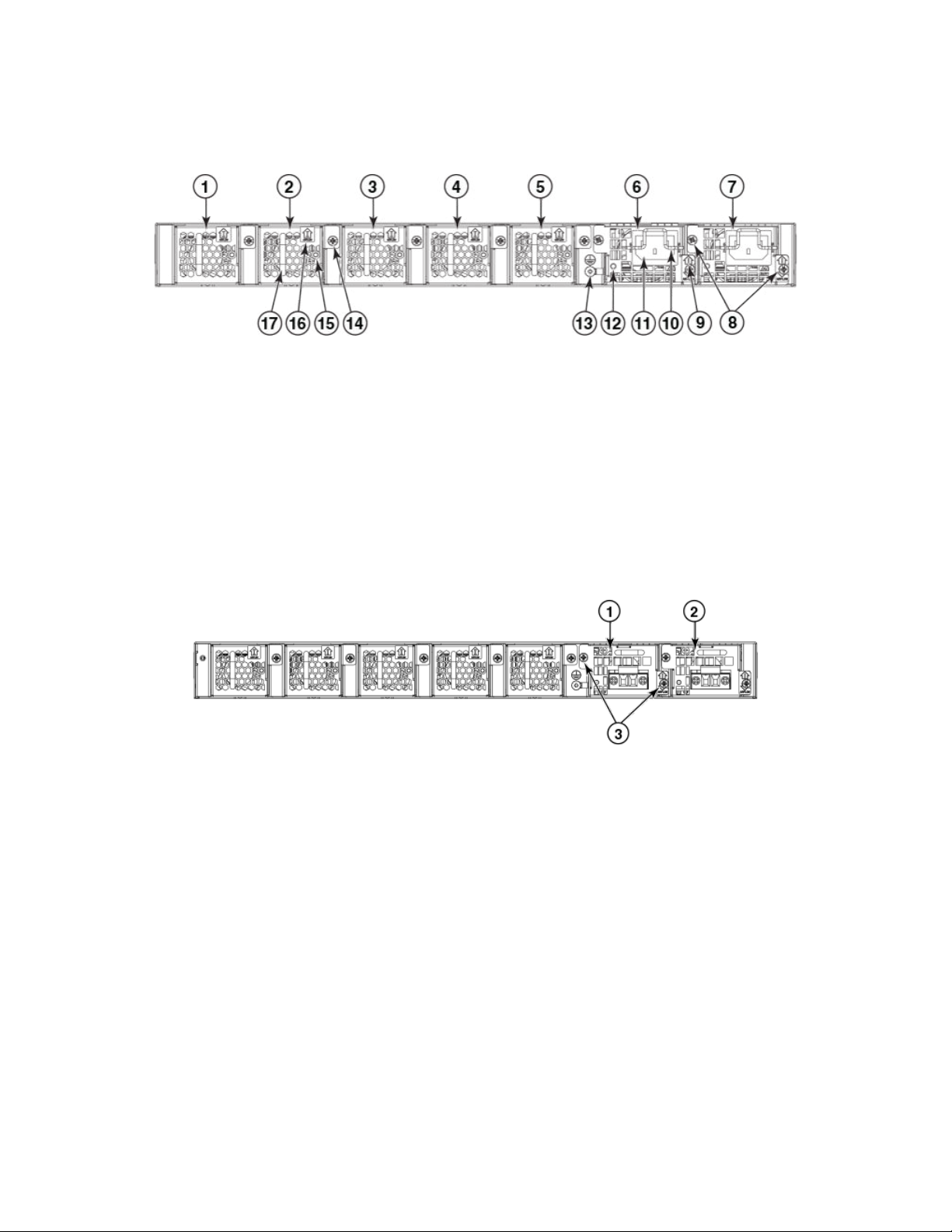
Nonport side view
The following illustration shows the non-port side of the VDX 6740, which contains the combined power supply and fan assemblies.
20 9036108-00
ExtremeSwitching VDX 6740 Hardware Installation Guide
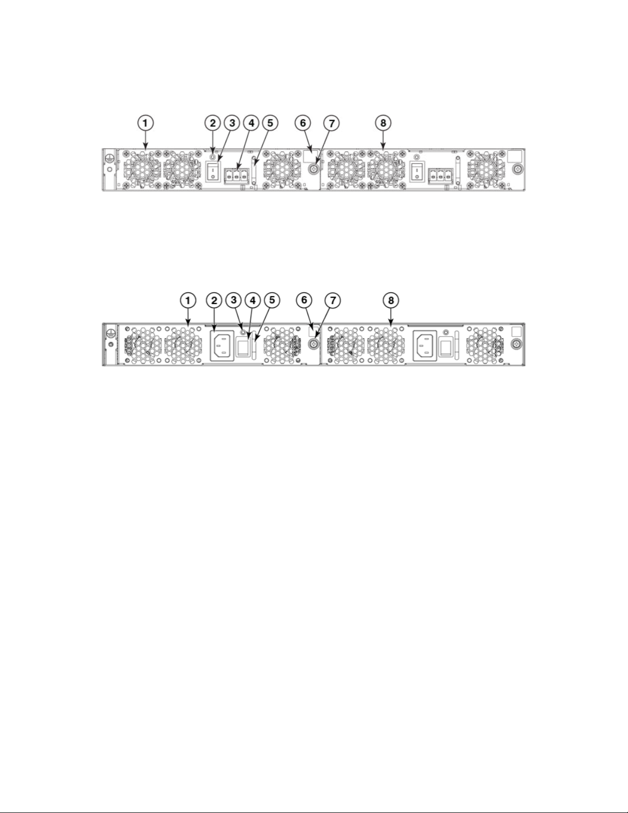
FIGURE 8 Non-port-side view of the DC VDX 6740
Hardware components
1. Power supply and fan assembly #2
2. Power supply and fan status LED
3. On/o switch
4. Power cord receptacle
5. Handle
6. Airow label
7. Captive screw
8. Power supply and fan assembly #1
FIGURE 9 Non-port-side view of the AC VDX 6740
1. Power supply and fan assembly #2
2. Power cord receptacle
3. Power supply and fan status LED
4. On/o switch
5. Handle
6. Airow label
7. Captive screw
8. Power supply and fan assembly #1
The following illustration shows the non-port side of the VDX 6740T, which house the separate power supplies and fans.
NOTE
The un-numbered features on the DC power supply are identical to the features on the AC power supply.
ExtremeSwitching VDX 6740 Hardware Installation Guide
9036108-00 21
Hardware components
FIGURE 10 Non-port-side view of the AC VDX 6740T
1. Fan #1
2. Fan #2
3. Fan #3
4. Fan #4
5. Fan #5
6. Power supply #1
7. Power supply #2
8. Captive screws
9. Airow label
FIGURE 11 Non-port-side view of the DC VDX 6740T
1. Power supply #1
2. Power supply #2
10. Plug retainer
11. Plug receptacle
12. Status LED
13. Ground lug
14. Captive screw
15. Status LED
16. Airow label
17. Handle
3. Captive screws
Extreme Networks inter-switch link trunks
In VCS mode, unless specically disabled, inter-switch link (ISL) Extreme Networks trunking between adjacent devices is automatic. All
ports must be in the same port group and must be congured at the same speed. There is a limit of sixteen ports per trunk group. No
separate licensing is required. Refer to the illustrations below for the exact port groups. On the VDX 6740T, ports in groups 3 and 3A, as
well as port groups 4 and 4A, cannot be trunked together. However, these ports can be trunked on the VDX 6740 when the 40 GbE
QSFP ports are congured in breakout mode. VDX 6740T 1GbE ports cannot be trunked.
NOTE
If connections are made to 16 dierent switches, only eight ports will be trunk ports while the other eight ports will be normal
ISL ports.
For instructions on conguring breakout mode and Extreme Networks trunking, refer to the Extreme Network OS Management
Conguration Guide.
22 9036108-00
ExtremeSwitching VDX 6740 Hardware Installation Guide
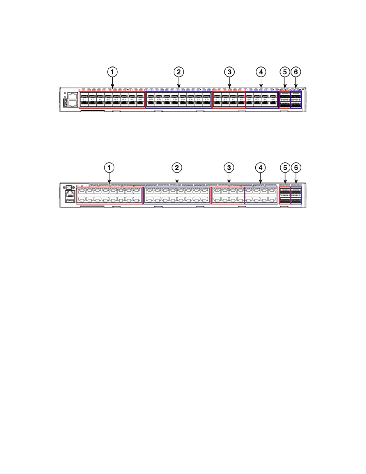
FIGURE 12 Port groups of the VDX 6740
Hardware components
1. Trunk Group 1 - 1/10 GbE SFP ports 1-16
2. Trunk Group 2 - 1/10 GbE SFP ports 17-32
3. Trunk Group 3 - 1/10 GbE SFP ports 33-40
FIGURE 13 Port groups of the VDX 6740T
1. Trunk Group 1 - 1/10 GbE BaseT ports 1-16
2. Trunk Group 2 - 1/10 GbE BaseT ports 17-32
3. Trunk Group 3 - 1/10 GbE BaseT ports 33-40
NOTE
For the VDX 6740T-1G variant, if you release Dynamic Ports On Demand (DPOD) licenses from any 10GbE ports on a 16port trunk congured with static 10G speed, reserve back those licenses, then perform the shutdown and no shutdown
commands on all trunk ports, the trunk bandwidth will not restore to the maximum 160 Gbps.
Trunking bandwidth limitations
4. Trunk group 4 - 1/10 GbE SFP ports 41-48
5. Trunk Group 3A - 40 GbE QSFP ports 49-50
6. Trunk Group 4A - 40 GbE QSFP ports 51-52
4. Trunk Group 4 - 1/10 GbE BaseT ports 41-48
5. Trunk Group 3A - 40 GbE QSFP ports 49-50
6. Trunk Group 4A - 40 GbE QSFP ports 51-52
For the VDX 6740T-1G variant, if you release Dynamic Ports On Demand (DPOD) licenses from any 10GbE ports on a 16-port trunk
congured with static 10G speed, reserve back those licenses, then enable the shutdown and no shutdown commands on all trunk
ports, the trunk bandwidth will not restore to the maximum 160 Gbps.
ExtremeSwitching VDX 6740 Hardware Installation Guide
9036108-00 23

24 9036108-00
ExtremeSwitching VDX 6740 Hardware Installation Guide
Preparing for the Installation
• Installation and safety considerations........................................................................................................................................................25
• Items required for the installation................................................................................................................................................................27
• Items included with the device.....................................................................................................................................................................27
Installation and safety considerations
You can install the devices in the following ways:
• As a standalone unit on a
• For the ExtremeSwitching VDX 6740 device:
– In a four-post EIA rack.
– In a two-post telecommunications (Telco) rack.
• For the ExtremeSwitching VDX 6740T device:
– In a four-post EIA rack.
– In a two-post Telco rack.
CAUTION
Make sure the airow around the front, and back of the device is not
restricted.
at surface.
DANGER
The procedures in this manual are for qualied service personnel.
Power precautions
To install and operate the device successfully, ensure compliance with the following safety requirements:
• The power supply standards provided in "Power Supply Specications" are met.
• The primary outlets are correctly wired, protected by a circuit breaker, and grounded in accordance with local electrical codes.
DANGER
Connect the power cord only to a grounded outlet.
• The supply circuit, line fusing, and wire size are adequate, as specied by the electrical rating on the device nameplate.
• This device might have more than one power cord. To reduce the risk of electric shock, disconnect both power cords before
servicing.
DANGER
Disconnect the power cord from all power sources to completely remove power from the device.
DANGER
This product is designed for an IT power system with phase-to-phase voltage of 230V. After operation of the protective
device, the equipment is still under voltage if it is connected to an IT power system.
ExtremeSwitching VDX 6740 Hardware Installation Guide
9036108-00 25
Installation and safety considerations
Environmental precautions
For successful installation and operation of the device, ensure that the following environmental requirements are met:
• Fans supplied with the device move air either front to back (exhaust) or back to front (intake). Be sure to align the device with the
airow pattern of any other devices in the rack. All equipment in the rack should force air in the same direction to avoid intake of
exhaust air.
CAUTION
Ensure that the airow direction of the power supply unit matches that of the installed fan tray. The power supplies
and fan trays are clearly labeled with either a green arrow with an "E", or an orange arrow with an "I."
• Ensure that the airow available at intake vents allows the maximum airow as specied in the product Technical Specications.
• Ensure that the ambient air temperature does not exceed that specied for maximum operational temperate in the product
Technical Specications.
EIA rack considerations
For successful installation and operation of the device in a rack, ensure the following rack requirements are met:
• The rack must be a standard EIA rack.
• For 1U devices, the rack space required is one rack unit (1U) 44.45 mm (1.75 in.) high and 440 mm (17.5 in.) wide.
• The equipment in the rack is grounded through a reliable branch circuit connection and maintains ground at all times. Do not
rely on a secondary connection to a branch circuit, such as a power strip.
• Ensure that the rack mounting does not impede airow or negatively aect temperature requirements, particularly if the device
is installed in a closed or multirack assembly. Ensure that airow openings on the port and nonport side of the device are not
obstructed.
CAUTION
Make sure the airow around the front, and back of the device is not
restricted.
• The additional weight of the device does not exceed the rack’s weight limits or unbalance the rack in any way.
• The rack is secured to ensure stability in case of unexpected movement, such as an earthquake.
DANGER
Make sure the rack housing the device is adequately secured to prevent it from becoming unstable or falling over.
Recommendations for cable management
The minimum radius to which a 50-micron cable can be bent under full tensile load is 5.1 cm (2 in.). For a cable under no tensile load,
that minimum is 3.0 cm (1.2 in.).
Cables can be organized and managed in a variety of ways; for example, use cable channels on the sides of the EIA rack or patch panels
to reduce the potential for tangling the cables. The following list provides some recommendations for cable management:
26 9036108-00
ExtremeSwitching VDX 6740 Hardware Installation Guide

Items included with the device
NOTE
You should not use tie wraps with optical cables because they are easily overtightened and can damage the optic bers. Velcrolike wraps are recommended.
• Plan for the rack space required for cable management before installing the device.
• Leave at least 1 m (3.28 ft) of slack for each port cable. This provides room to remove and replace the device, allows for
inadvertent movement of the rack, and helps prevent the cables from being bent to less than the minimum bend radius.
• For easier maintenance, label the cables and record the devices to which they are connected.
• Keep LEDs visible by routing port cables and other cables away from the LEDs.
Items required for the installation
The following items are required for installing,
• A workstation with an installed terminal emulator, such as HyperTerminal.
• An unused IP address and corresponding subnet mask and gateway address.
• A serial cable (provided).
• An Ethernet cable.
• Power cord (provided).
• (Optional) Access to an FTP server or Extreme-branded USB device for backing up the device conguration.
• (Optional) If mounting in the iDataplex IBM 15.5-inch depth rack, the Extreme Networks iDataplex rack mount kit.
conguring, and connecting the device for use in a network and fabric:
Items included with the device
The following items are included with the standard shipment of a
the items are included in the package and that no damage has occurred during shipping.
• The VDX 6740 or VDX 6740T chassis.
• Transceivers and cables as ordered
• One accessory kit, containing the following items:
– Serial cable with an RJ-45 connector (VDX 6740) or a mini-USB connector (VDX 6740T)
– 6 ft. power cords (2)
– Rubber feet, required for setting up the device as a standalone unit
– 2 GB USB drive
– China RoHS hazardous/toxic substance content chart
– EULA/Read-Me document
– Web pointer card for documentation
fully-congured VDX 6740. When you open the packaging, verify that
ExtremeSwitching VDX 6740 Hardware Installation Guide
9036108-00 27

28 9036108-00
ExtremeSwitching VDX 6740 Hardware Installation Guide

Mounting the Device
• Mounting options...............................................................................................................................................................................................29
• Mounting precautions......................................................................................................................................................................................30
• Standalone installation ....................................................................................................................................................................................30
• Installing the 1U Slim Rail Rack Mount Kit for Four-Post Racks (XBR-000291).................................................................31
• Installing the 1U, 1.5U, and 2U Universal Kit for Four Post Racks (XBR-R000295).........................................................35
• Time and items required.................................................................................................................................................................................36
• Parts list................................................................................................................................................................................................................. 36
• Flush-front mounting the device in the rack.......................................................................................................................................... 37
• Flush-rear (recessed) mounting the device in the rack......................................................................................................................44
• Installing the 1U, 1.5U, and 2U Mid-Mount Kit for Two-Post Racks (XBR-000165, XBR-000175,
and XBR-R000292)....................................................................................................................................................................................... 50
• Installing the 1U and 2U Flush-Mount Rack Kit for Two-Post Racks (XBR-000307 and XBR-R000293)...........56
• Installing the Universal Four-Post Rack Kit (XBR-R000296)........................................................................................................61
• Installing the Universal Two-Post Rack Kit (XBR-R000294).........................................................................................................74
Mounting options
You can mount the ExtremeSwitching VDX 6740 device in the following locations:
• As a standalone unit on a at surface, for example, a table top. Use the rubber feet included with the shipment to secure the
device on the surface. No other equipment is required for desktop installation.
• In a four-post EIA rack:
– Use the 1U Slim Rail Rack Mount Kit for Four-Post Racks (XBR-000291). Follow instructions in Installing the 1U Slim Rail
Rack Mount Kit for Four-Post Racks (XBR-000291) on page 31.
• In a two-post Telco rack:
– Use the 1U, 1.5U, and 2U Mid-Mount Kit for Two-Post Racks (XBR-R000292). Follow instructions in Installing the 1U,
1.5U, and 2U Mid-Mount Kit for Two-Post Racks (XBR-000165, XBR-000175, and XBR-R000292) on page 50.
– Use the 1U and 2U Flush-Mount Rack Kit for Two-Post Racks (XBR-000293). Follow instructions in Installing the 1U and
2U Flush-Mount Rack Kit for Two-Post Racks (XBR-000307 and XBR-R000293) on page 56.
You can mount the ExtremeSwitching VDX 6740T device in the following locations:
• As a standalone unit on a at surface, for example, a table top. Use the rubber feet included with the shipment to secure the
device on the surface. No other equipment is required for desktop installation.
• Use the 1U, 1.5U, and 2U Universal Rack Mount Kit for Four Post Racks (XBR-R000295). Follow instructions in Installing the
1U, 1.5U, and 2U Universal Kit for Four Post Racks (XBR-R000295) on page 35.
• In a four-post EIA rack. Use the Universal Four-Post Rack Kit (XBR-R000296). Follow instructions in Installing the Universal
Four-Post Rack Kit (XBR-R000296) on page 61.
• In a two-post Telco rack. Use the Universal Two-Post Rack Kit (XBR-R000294). Follow instructions in Installing the Universal
Two-Post Rack Kit (XBR-R000294) on page 74.
NOTE
Review the Mounting precautions on page 30 before mounting the device and ensure that you have considered all
precautions in Installation and safety considerations on page 25.
ExtremeSwitching VDX 6740 Hardware Installation Guide
9036108-00 29
Mounting precautions
NOTE
Rack mount kits described in this document are those supported at the time of publication. For the latest support information,
contact your Extreme Networks representative.
Mounting precautions
The following precautions specically apply to mounting the device.
DANGER
Use safe lifting practices when moving the product.
DANGER
Mount the devices you install in a rack as low as possible. Place the heaviest device at the bottom and progressively place
lighter devices above.
CAUTION
Make sure the airow around the front, and back of the device is not
restricted.
CAUTION
Use the screws specied in the procedure. Using longer screws can damage the
device.
CAUTION
To prevent damage to the chassis and components, never attempt to lift the chassis using the fan or power supply handles.
These handles were not designed to support the weight of the chassis.
Refer to the "EIA rack considerations" in Installation and safety considerations on page 25.
Standalone installation
Complete the following steps to install the device as a standalone unit on a table top.
1. Unpack the device and verify the items listed under "Items included with this device" are present and undamaged.
2. Apply the adhesive rubber feet to the device. The rubber feet help prevent the device from sliding
a) Clean the indentations at each corner of the bottom of the device to ensure that they are free of dust or other debris that
might lessen the adhesion of the feet.
b) With the adhesive side against the chassis, place one rubber foot in each indentation and press into place.
3. Place the device on a at, sturdy surface.
4. Provide power to the device as described under "Providing power to the device."
o the supporting surface.
NOTE
Do not connect the device to the network until the IP address is correctly set. For instructions on how to set the IP
address, refer to "Conguring the device IP address."
30 9036108-00
ExtremeSwitching VDX 6740 Hardware Installation Guide
 Loading...