

Extreme Networks ExtremeRouting SLX 9850-4, ExtremeRouting SLX 9850-8 Hardware Installation Manual

HARDWARE INSTALLATION GUIDE
ExtremeRouting SLX 9850-4
Hardware Installation Guide
9035474-02 Rev AA
June 2019

Copyright © 2019 Extreme Networks, Inc. All Rights Reserved.
Legal Notice
Extreme Networks, Inc. reserves the right to make changes in specications and other information contained in this document and its
website without prior notice. The reader should in all cases consult representatives of Extreme Networks to determine whether any such
changes have been made.
The hardware, rmware, software or any specications described or referred to in this document are subject to change without notice.
Trademarks
Extreme Networks and the Extreme Networks logo are trademarks or registered trademarks of Extreme Networks, Inc. in the United
States and/or other countries.
All other names (including any product names) mentioned in this document are the property of their respective owners and may be
trademarks or registered trademarks of their respective companies/owners.
For additional information on Extreme Networks trademarks, please see: www.extremenetworks.com/company/legal/trademarks
Open Source Declarations
Some software
declarations can be found at: www.extremenetworks.com/support/policies/software-licensing
les have been licensed under certain open source or third-party licenses. End-user license agreements and open source
2 9035474-02 Rev AA
ExtremeRouting SLX 9850-4 Hardware Installation Guide

Contents
Preface...................................................................................................................................................................................................................................7
Conventions..................................................................................................................................................................................................................................................7
Notes, cautions, and warnings.....................................................................................................................................................................................................7
Text formatting conventions.........................................................................................................................................................................................................7
Command syntax conventions....................................................................................................................................................................................................8
Documentation and Training.................................................................................................................................................................................................................8
Training..................................................................................................................................................................................................................................................8
Getting Help................................................................................................................................................................................................................................................. 8
Subscribing to Service Notications.........................................................................................................................................................................................9
Providing Feedback to Us......................................................................................................................................................................................................................9
About this Document.......................................................................................................................................................................................................11
Supported hardware and software...................................................................................................................................................................................................11
Auto Level Support - Table 1...................................................................................................................................................................................................12
What is new in this document............................................................................................................................................................................................................16
Device Overview...............................................................................................................................................................................................................17
Device slot numbering: port-side.....................................................................................................................................................................................................17
Device slot numbering: nonport-side.............................................................................................................................................................................................18
Device management options.............................................................................................................................................................................................................20
Preparing for the Installation..........................................................................................................................................................................................23
Safety precautions..................................................................................................................................................................................................................................23
General precautions......................................................................................................................................................................................................................23
ESD precautions............................................................................................................................................................................................................................ 23
Lifting precautions.........................................................................................................................................................................................................................24
Laser precautions.......................................................................................................................................................................................................................... 24
Facility requirements .............................................................................................................................................................................................................................24
Time and items required for installation.........................................................................................................................................................................................25
Quick installation checklists................................................................................................................................................................................................................26
Pre-installation tasks....................................................................................................................................................................................................................26
Installation and initial conguration.........................................................................................................................................................................................27
Unpacking the shipping carton......................................................................................................................................................................................................... 28
Shipping carton contents.....................................................................................................................................................................................................................29
Mounting the Device........................................................................................................................................................................................................31
Mounting options....................................................................................................................................................................................................................................31
Mounting safety precautions..............................................................................................................................................................................................................31
Required tools and equipment..........................................................................................................................................................................................................32
Device surface preparation..................................................................................................................................................................................................................32
Installing a device on a four-post rack............................................................................................................................................................................................32
Flush mount.....................................................................................................................................................................................................................................34
Recessed mount............................................................................................................................................................................................................................37
Installing a device on a two-post rack............................................................................................................................................................................................ 39
Flush mount.....................................................................................................................................................................................................................................41
Middle mount .................................................................................................................................................................................................................................43
Installing an SLX-9850-4 NEBS kit..............................................................................................................................................................................................44
Installing cable management combs .............................................................................................................................................................................................54
ExtremeRouting SLX 9850-4 Hardware Installation Guide
9035474-02 Rev AA 3

Initial Setup and Verication.......................................................................................................................................................................................... 57
Initial setup and conguration checklist.........................................................................................................................................................................................57
Items required...........................................................................................................................................................................................................................................58
Providing power to the device........................................................................................................................................................................................................... 58
Connecting an AC power cord................................................................................................................................................................................................. 59
Connecting a DC power cord................................................................................................................................................................................................... 61
For NEBS-compliant installation with AC and DC..........................................................................................................................................................63
Establishing a serial connection........................................................................................................................................................................................................63
Conguring a static IP address..........................................................................................................................................................................................................66
Conguring IPv6 address .........................................................................................................................................................................................................66
Establishing an Ethernet connection...............................................................................................................................................................................................68
Customizing the chassis and host names....................................................................................................................................................................................69
Conguring the DNS service............................................................................................................................................................................................................. 70
Setting the date and time.....................................................................................................................................................................................................................70
Setting the clock (date and time)............................................................................................................................................................................................. 70
Time zones.......................................................................................................................................................................................................................................71
Time synchronization...................................................................................................................................................................................................................71
Synchronizing local time using NTP......................................................................................................................................................................................71
Setting the time zone................................................................................................................................................................................................................... 72
Verifying correct operation..................................................................................................................................................................................................................72
Backing up the conguration.............................................................................................................................................................................................................73
Powering down the device.................................................................................................................................................................................................................. 73
Installing cable management kit........................................................................................................................................................................................................74
Monitoring the Device..................................................................................................................................................................................................... 75
Monitoring Overview............................................................................................................................................................................................................................. 75
Interpreting management module LEDs...................................................................................................................................................................................... 75
Interpreting interface module LEDs................................................................................................................................................................................................77
Interpreting power supply module LEDs......................................................................................................................................................................................80
Interpreting fan module LEDs........................................................................................................................................................................................................... 83
Interpreting switch fabric module LEDs........................................................................................................................................................................................84
Management Modules.....................................................................................................................................................................................................87
Management module overview.........................................................................................................................................................................................................87
Front panel and port description.............................................................................................................................................................................................87
Precautions specic to the management modules.................................................................................................................................................................. 88
ESD ground strap connection points..............................................................................................................................................................................................88
Time and items required for installation and replacement.....................................................................................................................................................90
Removing a management module..................................................................................................................................................................................................91
Installing a management module.....................................................................................................................................................................................................92
Verifying management module operation....................................................................................................................................................................................93
Interface Modules.............................................................................................................................................................................................................95
Interface module overview .................................................................................................................................................................................................................95
Front panel and port description.............................................................................................................................................................................................95
Precautions specic to the interface modules............................................................................................................................................................................97
Time and items required for installation and replacement.....................................................................................................................................................97
Inserting an interface module.............................................................................................................................................................................................................97
Removing or replacing an interface module.............................................................................................................................................................................100
Verifying interface module operation...........................................................................................................................................................................................101
Power Supply Modules.................................................................................................................................................................................................103
4 9035474-02 Rev AA
ExtremeRouting SLX 9850-4 Hardware Installation Guide

Power supply module overview.....................................................................................................................................................................................................103
Power input and cable options..............................................................................................................................................................................................105
Power supply numbering........................................................................................................................................................................................................105
Precautions specic to the power supply module................................................................................................................................................................. 106
Time and items required for removal and replacement.......................................................................................................................................................106
Removing an AC power supply module.................................................................................................................................................................................... 106
Inserting an AC power supply module........................................................................................................................................................................................108
Removing a DC power supply module.......................................................................................................................................................................................109
Inserting a DC power supply module..........................................................................................................................................................................................109
Verifying power supply module operation.................................................................................................................................................................................110
High Voltage Power Supply Unit supporting AC and DC Voltages................................................................................................................................110
Connector Type...........................................................................................................................................................................................................................112
Power Cords................................................................................................................................................................................................................................. 112
Fan Modules....................................................................................................................................................................................................................115
Fan module overview.........................................................................................................................................................................................................................115
Precautions specic to the fan module.......................................................................................................................................................................................115
Time and items required for replacement..................................................................................................................................................................................115
Removing a fan module....................................................................................................................................................................................................................116
Inserting a fan module....................................................................................................................................................................................................................... 117
Verifying fan module operation......................................................................................................................................................................................................117
Air lter replacement schedule.......................................................................................................................................................................................................117
Switch Fabric Modules..................................................................................................................................................................................................119
Switch fabric module overview.......................................................................................................................................................................................................119
Precautions specic to the switch fabric module....................................................................................................................................................................120
Time and items required for replacement..................................................................................................................................................................................121
Removing a switch fabric module.................................................................................................................................................................................................121
Inserting a switch fabric module.................................................................................................................................................................................................... 122
Verifying switch fabric module operation...................................................................................................................................................................................124
Transceivers and cables................................................................................................................................................................................................125
Supported transceivers and cables.............................................................................................................................................................................................. 125
Time and items required................................................................................................................................................................................................................... 125
Precautions specic to transceivers and cables......................................................................................................................................................................126
Cleaning the ber-optic connectors.............................................................................................................................................................................................126
Managing cables.................................................................................................................................................................................................................................. 127
Installing an SFP+ transceiver.........................................................................................................................................................................................................127
Replacing an SFP+ transceiver...................................................................................................................................................................................................... 129
Installing a QSFP28 transceiver....................................................................................................................................................................................................131
Replacing a QSFP28 transceiver.................................................................................................................................................................................................133
Breakout cables....................................................................................................................................................................................................................................134
Verifying transceiver operation.......................................................................................................................................................................................................134
Hardware Maintenance Schedule...............................................................................................................................................................................135
Hardware maintenance schedule.................................................................................................................................................................................................. 135
ExtremeRouting SLX 9850 Technical Specications........................................................................................................................................... 137
System specications.........................................................................................................................................................................................................................137
Ethernet....................................................................................................................................................................................................................................................138
LEDs..........................................................................................................................................................................................................................................................138
Other......................................................................................................................................................................................................................................................... 139
Weight and physical dimensions................................................................................................................................................................................................... 139
ExtremeRouting SLX 9850-4 Hardware Installation Guide
9035474-02 Rev AA 5

Environmental requirements........................................................................................................................................................................................................... 140
Power supply specications (per PSU).......................................................................................................................................................................................141
Power consumption (typical conguration)...............................................................................................................................................................................141
Power consumption (maximum conguration)........................................................................................................................................................................141
Power consumption (modules) (typical conguration)..........................................................................................................................................................142
Power consumption (modules) (maximum conguration)..................................................................................................................................................142
Data port specications (Ethernet)................................................................................................................................................................................................143
Serial port specications (pinout RJ-45)....................................................................................................................................................................................143
Serial port specications (protocol)...............................................................................................................................................................................................144
Memory specications.......................................................................................................................................................................................................................144
Regulatory compliance (EMC)........................................................................................................................................................................................................144
Regulatory compliance (safety)...................................................................................................................................................................................................... 144
Regulatory compliance (environmental)..................................................................................................................................................................................... 144
Regulatory Statements.................................................................................................................................................................................................147
BSMI statement (Taiwan)..................................................................................................................................................................................................................147
Canadian requirements......................................................................................................................................................................................................................147
CE statement.........................................................................................................................................................................................................................................147
China ROHS.......................................................................................................................................................................................................................................... 148
FCC warning (US only)...................................................................................................................................................................................................................... 148
Germany statement.............................................................................................................................................................................................................................148
KCC statement (Republic of Korea)..............................................................................................................................................................................................148
VCCI statement.....................................................................................................................................................................................................................................149
Japan power cord ................................................................................................................................................................................................................................149
Cautions and Danger Notices..................................................................................................................................................................................... 151
Cautions...................................................................................................................................................................................................................................................151
General cautions......................................................................................................................................................................................................................... 151
Electrical cautions.......................................................................................................................................................................................................................152
Cautions related to equipment weight...............................................................................................................................................................................154
Danger Notices.....................................................................................................................................................................................................................................154
General dangers..........................................................................................................................................................................................................................155
Dangers related to equipment weight................................................................................................................................................................................155
Electrical dangers........................................................................................................................................................................................................................156
Laser dangers.............................................................................................................................................................................................................................. 157
6 9035474-02 Rev AA
ExtremeRouting SLX 9850-4 Hardware Installation Guide
Preface
• Conventions............................................................................................................................................................................................................7
• Documentation and Training............................................................................................................................................................................8
• Getting Help............................................................................................................................................................................................................8
• Providing Feedback to Us.................................................................................................................................................................................9
This section discusses the conventions used in this guide, ways to provide feedback, additional help, and other Extreme Networks
publications.
Conventions
This section discusses the conventions used in this guide.
Notes, cautions, and warnings
Notes, cautions, and warning statements may be used in this document. They are listed in the order of increasing severity of potential
hazards.
NOTE
A Note provides a tip, guidance, or advice, emphasizes important information, or provides a reference to related information.
ATTENTION
An Attention statement indicates a stronger note, for example, to alert you when trac might be interrupted or the device might
reboot.
®
CAUTION
A Caution statement alerts you to situations that can be potentially hazardous to you or cause damage to hardware,
rmware, software, or data.
DANGER
A Danger statement indicates conditions or situations that can be potentially lethal or extremely hazardous to you. Safety
labels are also attached directly to products to warn of these conditions or situations.
Text formatting conventions
Text formatting conventions such as boldface, italic, or Courier font may be used to highlight specic words or phrases.
Format Description
bold text Identies command names.
Identies keywords and operands.
Identies the names of GUI elements.
Identies text to enter in the GUI.
italic text Identies emphasis.
Identies variables.
Identies document titles.
ExtremeRouting SLX 9850-4 Hardware Installation Guide
9035474-02 Rev AA 7

Documentation and Training
Format Description
Courier font
Identies CLI output.
Identies command syntax examples.
Command syntax conventions
Bold and italic text identify command syntax components. Delimiters and operators
relationships.
Convention Description
bold text Identies command names, keywords, and command options.
italic text Identies a variable.
[ ] Syntax components displayed within square brackets are optional.
Default responses to system prompts are enclosed in square brackets.
{ x | y | z } A choice of required parameters is enclosed in curly brackets separated by vertical bars. You must select
one of the options.
x | y A vertical bar separates mutually exclusive elements.
< > Nonprinting characters, for example, passwords, are enclosed in angle brackets.
... Repeat the previous element, for example, member[member...].
\ Indicates a “soft” line break in command examples. If a backslash separates two lines of a command
input, enter the entire command at the prompt without the backslash.
dene groupings of parameters and their logical
Documentation and Training
To nd Extreme Networks product guides, visit our documentation pages at:
Current Product Documentation www.extremenetworks.com/documentation/
Archived Documentation (for earlier versions and
legacy products)
Release Notes www.extremenetworks.com/support/release-notes
Hardware/Software Compatibility Matrices https://www.extremenetworks.com/support/compatibility-matrices/
White papers, data sheets, case studies, and other
product resources
www.extremenetworks.com/support/documentation-archives/
https://www.extremenetworks.com/resources/
Training
Extreme Networks
visit www.extremenetworks.com/education/.
oers product training courses, both online and in person, as well as specialized certications. For more information,
Getting Help
If you require assistance, contact Extreme Networks using one of the following methods:
8 9035474-02 Rev AA
ExtremeRouting SLX 9850-4 Hardware Installation Guide

Providing Feedback to Us
Extreme Portal Search the GTAC (Global Technical Assistance Center) knowledge base, manage support cases and service
contracts, download software, and obtain product licensing, training, and certications.
The Hub A forum for Extreme Networks customers to connect with one another, answer questions, and share ideas and
feedback. This community is monitored by Extreme Networks employees, but is not intended to replace specic
guidance from GTAC.
Call GTAC For immediate support: 1-800-998-2408 (toll-free in U.S. and Canada) or +1 408-579-2826. For the support
phone number in your country, visit: www.extremenetworks.com/support/contact
Before contacting Extreme Networks for technical support, have the following information ready:
• Your Extreme Networks service contract number and/or serial numbers for all involved Extreme Networks products
• A description of the failure
• A description of any action(s) already taken to resolve the problem
• A description of your network environment (such as layout, cable type, other relevant environmental information)
• Network load at the time of trouble (if known)
• The device history (for example, if you have returned the device before, or if this is a recurring problem)
• Any related RMA (Return Material Authorization) numbers
Subscribing to Service Notications
You can subscribe to email notications for product and software release announcements, Vulnerability Notices, and Service
Notications.
1. Go to www.extremenetworks.com/support/service-notication-form.
2. Complete the form with your information (all elds are required).
3. Select the products for which you would like to receive notications.
NOTE
You can modify your product selections or unsubscribe at any time.
4. Click Submit.
Providing Feedback to Us
Quality is our
document. We are always striving to improve our documentation and help you work better, so we want to hear from you! We welcome all
feedback but especially want to know about:
• Content errors or confusing or conicting information.
• Ideas for improvements to our documentation so you can nd the information you need faster.
• Broken links or usability issues.
rst concern at Extreme Networks, and we have made every eort to ensure the accuracy and completeness of this
If you would like to provide feedback to the Extreme Networks Information Development team, you can do so in two ways:
• Use our short online feedback form at https://www.extremenetworks.com/documentation-feedback/.
• Email us at documentation@extremenetworks.com.
Please provide the publication title, part number, and as much detail as possible, including the topic heading and page number if
applicable, as well as your suggestions for improvement.
ExtremeRouting SLX 9850-4 Hardware Installation Guide
9035474-02 Rev AA 9

10 9035474-02 Rev AA
ExtremeRouting SLX 9850-4 Hardware Installation Guide

About this Document
• Supported hardware and software..............................................................................................................................................................11
• What is new in this document.......................................................................................................................................................................16
Supported hardware and software
The following tables list the major eld-replaceable units (FRUs), and rack mount kits supported for the ExtremeRouting SLX 9850-4
and the ExtremeRouting SLX 9850-8 devices.
NOTE
This section only lists the system components that are software-dependent and the rack kits. It is not a comprehensive list of
eld-replaceable units (FRUs) or accessory kit items.
TABLE 1 SLX 9850 chassis bundles
Part number Long description Introduced OS Currently supported
BR-SLX9850-8-BND-AC SLX 9850 8-slot chassis with 1 management
module, 5 switch fabric modules, 5 3000W AC
power supplies, 3 fan modules, and accessory kit.
Power cord not included
BR-SLX9850-8-BND-DC SLX 9850 8-slot chassis with 1 management
module, 5 switch fabric modules, 5 3000W DC
power supplies, 3 fan modules, and accessory kit.
Power cord not included
SLX-OS 16r.1.00 Yes
SLX-OS 16r.1.00 Yes
TABLE 2 SLX 9850-4chassis bundles
Part number Long description Introduced OS Currently supported
BR-SLX9850-4-BND-AC SLX 9850 4-slot chassis with 1 management
module, 5 switch fabric modules, 3 3000W AC
power supplies, 3 fan modules, and accessory kit.
Power cord not included
BR-SLX9850-4-BND-DC SLX 9850 4-slot chassis with 1 management
module, 5 switch fabric modules, 3 3000W DC
power supplies, 3 fan modules, and accessory kit.
Power cord not included
SLX-OS 16r.1.00 Yes
SLX-OS 16r.1.00 Yes
TABLE 3 SLX 9850-4chassis bundle
Part number Long description Introduced OS Currently supported
BR-SLX9850-4-BND-AC SLX 9850 4-slot chassis with 1 management
module, 5 switch fabric modules, 3 3000W AC
power supplies, 3 fan modules, and accessory kit.
Power cord not included
SLX-OS 16r.1.00 Yes
TABLE 4 SLX 9850 management module
Part number Long description Introduced OS Currently supported
BR-SLX9850-MM SLX 9850 management module for 4-slot and 8-
slot systems, includes 16GB RAM, 2 internal Solid
State Drives, 4-Core Intel CPU, 2 USB 3.0 ports, 2
SLX-OS 16r.1.00 Yes
ExtremeRouting SLX 9850-4 Hardware Installation Guide
9035474-02 Rev AA 11

Supported hardware and software
TABLE 4 SLX 9850 management module (continued)
Part number Long description Introduced OS Currently supported
RJ-45 console ports,10GbE Service port and
1GbE Management port
BR-SLX9850-MM SLX 9850 management module for 4-slot and 8-
slot systems, includes 32GB RAM, 2 internal Solid
State Drives, 4-Core Intel CPU, 2 USB 3.0 ports, 2
RJ-45 console ports,10GbE Service port and
1GbE Management port
SLX-OS 17r.2.00 Yes
NOTE
The SLX-OS 17r.2.00 introduced the Optiscale feature that requires a 32GB Management Module. However, the 32GB
Management Module is also supported using the SLX-OS 16r.1.00 and later code versions, even though only 16GB of
memory will be utilized.
A newly inserted LineCard (LC) may get into a faulty state with "Incompatible LC" error message seen on console, due to a mismatch of
SLX-OS versions when the installed OS on the Management module (MM) and LC are a mix of 32bit and 64bit OS versions.
Refer to the two tables providing the Auto level support matrices for 32-bit and 64-bit MM and 32-bit and 64-bit LineCards (LC)
running the SLX-OS software versions specied below.
Auto Level Support - Table 1
Auto Level Support 32-bit Linecard (LC) 64-bit Linecard (LC)
17r.101a or lower 17r.1.01b 17r.2.00 or higher
32-bit Mgmt. Module (MM)
17r.101a or lower Supported Supported Not Supported*
17r.1.01b Supported Supported Supported**
64-bit Mgmt. Module (MM)
17r.2.00 or higher Not Supported* Supported** Supported
NOTE
* Netinstall can be used to install the 32-bit or 64-bit SLX-OS rmware on the LC to match the MM.* Netinstall can be used to
install the 32-bit or 64-bit SLX-OS rmware on the LC to match the MM.** In the event of a boot failure and a failed auto-level,
please revert to the unsupported case and contact GTAC for assistance with a Netinstall to load the appropriate rmware.Table
Figure 2:
NOTE
In dual MM systems, a mix of SLX-OS 32-bit and 64-bit is not supported.
TABLE 5 Auto Level Support - Table 2
Auto Level Support 32-bit Mgmt. Module (MM) 64-bit Mgmt. Module (MM)
17r.101a or lower 17r.1.01b 17r.2.00 or higher
32-bit Mgmt. Module (MM)
17r.101a or lower Supported Supported Not Supported
17r.1.01b Supported Supported Supported
64-bit Mgmt. Module (MM)
17r.2.00 or higher Not Supported Supported Supported
12 9035474-02 Rev AA
ExtremeRouting SLX 9850-4 Hardware Installation Guide

Supported hardware and software
TABLE 6 SLX 9850-4 switch fabric module
Part number Long description Introduced OS Currently supported
BR-SLX9850-4-SFM SLX 9850 switch fabric module for 4-slot chassis SLX-OS 16r.1.00 Yes
TABLE 7 Supported SLX 9850 interface modules
Part number Long description Introduced OS Currently supported
BR-SLX9850-10Gx72S-D SLX 9850 SLX 9850 72-port 10 GbE/1 GbE (D)
interface module with IPv4/IPv6 hardware support.
Requires SFP+ optics for 10 GbE connectivity and
SFP optics for 1 GbE connectivity. Supports 750K
MAC, 256K IPv4 routes and 64K IPv6 routes.
BR-SLX9850-10Gx72S-M SLX 9850 SLX 9850 72-port 10 GbE/1 GbE (M)
interface module with IPv4/IPv6/MPLS hardware
support. Requires SFP+ optics for 10 GbE
connectivity and SFP optics for 1 GbE connectivity.
Supports 750K MAC, 256K IPv4 routes and 64K
IPv6 routes.
BR-SLX9850-10Gx72S-N SLX 9850 SLX 9850 72-port 10 GbE/1 GbE
interface module. Same features and specications as
BR-SLX9850-10 Gx72S-D, with the addition of
Network Packet Broker (NPB) support.
BR-SLX9850-100Gx36CQ-D SLX 9850 SLX 9850 36-port 100 GbE,60-port 40
GbE, or 240-port 10 GbE ex-speed (D) interface
module with IPv4/IPv6 hardware support. Requires
QSFP28,QSFP+ optics & 40 GbE to 10 GbE
breakout(10 GbE) connectivity. Supports 750K MAC,
256K IPv4 & 64K IPv6 routes.
BR-SLX9850-100Gx36CQ-M SLX 9850 36-port 100 GbE,60-port 40 GbE,or
240-port 10 GbE ex-speed (M) interface module
with IPv4/IPv6/MPLS hardware support. Requires
QSFP28,QSFP+ optics & 40 GbE to 10 GbE
breakout(10 GbE) connectivity. Supports 750K MAC,
256K IPv4 & 64K IPv6 routes.
BR-SLX9850-100Gx36CQ-N SLX 9850 SLX 9850 36-port 100 GbE, 60-port
40 GbE, or 240-port 10 GbE ex-speed interface
module. Same features and specications as BRSLX9850-100Gx36CQ-D, with the addition of
Network Packet Broker (NPB) support.
SLX-OS 16r.1.01 Yes
SLX-OS 16r.1.00 Yes
SLX-OS 16r.1.00 Yes
SLX-OS 16r.1.01 Yes
SLX-OS 16r.1.00 Yes
SLX-OS 16r.1.00 Yes
The following table is a general reference to the types of transceivers supported on interface modules used by the device.
TABLE 8 Supported transceivers and cables
Interface module Transceiver type and description Introduced OS Currently supported
BR-SLX9850-100Gx36CQ-M
(36-port 100GbE, 60-port
40GbE, or 240-port 10GbE
ex-speed) interface module
ExtremeRouting SLX 9850-4 Hardware Installation Guide
9035474-02 Rev AA 13
100G-QSFP28-SR4 - 100 GbE QSFP28 optic (MTP
1x12), SR4, for distances up to 100 m over MMF
100G-QSFP28-LR4-10KM - 100 GbE QSFP28 optic
(LC), LR4, for distances up to 10 km over SMF
100G-QSFP28-LR4L-2KM - 100 GbE QSFP28 optic
(LC), LR4-Lite, for distances up to 2 km over SMF
100G-QSFP28-CWDM4-2KM - 100 GbE QSFP28 optic
(LC), CWDM4, for distances up to 2 km over SMF
SLX-OS 16r.1.00 Yes
SLX-OS 16r.1.00 Yes
SLX-OS 16r.1.00 Yes
SLX-OS 16r.1.00 Yes

Supported hardware and software
TABLE 8 Supported transceivers and cables (continued)
Interface module Transceiver type and description Introduced OS Currently supported
BR-SLX9850-10Gx72S-M
(72-port 10GbE/1GbE)
interface module
100G-QSFP28-LR4-LP-10KM - 100 GbE QSFP28
optic (LC), LR4 low power, for distances up to 10 km over
SMF
40G-QSFP-SR4 - 40GBASE-SR4 QSFP+ optic (MTP
1x8 or 1x12), 100m over MMF, 1-pack
40G-QSFP-SR4 - 40GBASE-SR4 QSFP+ optic (MTP
1x8 or 1x12), 100m over MMF, compatible with
10GBASE-SR, 10G breakout-capable, 1-pack
40G-QSFP-ESR4 - 40GBASE-SR4 QSFP+ optic (MTP
1x8 or 1x12), 300m over MMF, compatible with
10GBASE-SR, 10G breakout-capable, 1-pack
40G-QSFP-LR4 - 40GBase-LR4 QSFP+ optic (LC), for
up to 10km over SMF, 1-pack
40G-QSFP-QSFP-C-0101 - 40GE Direct Attached
QSFP+ to QSFP+ Active Copper cable, 1m, 1-pack
40G-QSFP-QSFP-C-0301 - 40GE Direct Attached
QSFP+ to QSFP+ Active Copper cable, 3m, 1-pack
40G-QSFP-QSFP-C-0501 - 40GE Direct Attached
QSFP+ to QSFP+ Active Copper cable, 5m, 1-pack
40G-QSFP-QSFP-AOC-1001 - 40GE Direct Attached
QSFP+ to QSFP+ Active Optical Cable, 10m, 1-pack
40G-QSFP-QSFP-C-0101 - 4x10GE Direct Attached
QSFP+ to 4 SFP+ Active Copper Breakout Cable, 1m, 1pack
40G-QSFP-4SFP-C-0301 - 4x10GE Direct Attached
QSFP+ to 4 SFP+ Active Copper Breakout Cable, 3m, 1pack
40G-QSFP-4SFP-C-0501 - 4x10GE Direct Attached
QSFP+ to 4 SFP+ Active Copper Breakout Cable, 5m, 1pack
40G-QSFP-4SFP-AOC-1001 - 4x10GE Direct Attached
QSFP+ to 4 SFP+ Active Optical Breakout Cable, 10m, 1pack
10G-SFPP-USR - 10GE USR SFP+ optic (LC), target
range 100m over MMF, 1-pack
10G-SFPP-SR - 10GBASE-SR, SFP+ optic (LC), target
range 300m over MMF
10G-SFPP-SR-8 - 10GBASE-SR, SFPP MMF LC
CONNECTOR 8-PACK
10G-SFPP-LR - 10GBASE-LR, SFP+ optic (LC), for up to
10km over SMF
10G-SFPP-LR-8 - 10GBASE-LR,SFPP SMF LC
CONNECTOR 8-PACK
10G-SFPP-ER - 10GBASE-ER SFP+ optic (LC), for up to
40km over SMF
10G-SFPP-TWX-0101 - DIRECT ATTACHED SFPP
ACTIVE COPPER,1M,1-PACK
10G-SFPP-TWX-0108 - DIRECT ATTACHED SFPP
COPPER,1M,8-PACK
SLX-OS 16r.1.00 Yes
SLX-OS 16r.1.00 Yes
SLX-OS 16r.1.00 Yes
SLX-OS 16r.1.00 Yes
SLX-OS 16r.1.00 Yes
SLX-OS 16r.1.00 Yes
SLX-OS 16r.1.00 Yes
SLX-OS 16r.1.00 Yes
SLX-OS 16r.1.00 Yes
SLX-OS 16r.1.00 Yes
SLX-OS 16r.1.00 Yes
SLX-OS 16r.1.00 Yes
SLX-OS 16r.1.00 Yes
SLX-OS 16r.1.00 Yes
SLX-OS 16r.1.00 Yes
SLX-OS 16r.1.00 Yes
SLX-OS 16r.1.00 Yes
SLX-OS 16r.1.00 Yes
SLX-OS 16r.1.00 Yes
SLX-OS 16r.1.01 Yes
SLX-OS 16r.1.01 Yes
14 9035474-02 Rev AA
ExtremeRouting SLX 9850-4 Hardware Installation Guide

Supported hardware and software
TABLE 8 Supported transceivers and cables (continued)
Interface module Transceiver type and description Introduced OS Currently supported
10G-SFPP-TWX-0301 - DIRECT ATTACHED SFPP
ACTIVE COPPER,3M,1-PACK
10G-SFPP-TWX-0308 - DIRECT ATTACHED SFPP
COPPER,3M,8-PACK
10G-SFPP-TWX-0501 - DIRECT ATTACHED SFPP
ACTIVE COPPER,5M,1-PACK
10G-SFPP-TWX-0508 - DIRECT ATTACHED SFPP
COPPER,5M,8-PACK
E1MG-LX-OM - 1000Base-LX SFP optic, SMF, LC
connector, Optical Monitoring Capable
E1MG-LX-OM-8 - 1000Base-LX SFP optic 8 Pack, SMF,
LC connector, Optical Monitoring Capable
E1MG-SX-OM - 1000Base-SX SFP optic, MMF, LC
connector, Optical Monitoring Capable
E1MG-SX-OM - 1000Base-SX SFP optic, MMF, LC
connector, Optical Monitoring Capable
E1MG-SX-OM-8 - 1000Base-SX SFP optic 8 Pack,
MMF, LC connector, Optical Monitoring Capable
E1MG-BXD - 1000Base-BXD SFP optic SMF, transmits
at 1490nm and receives at 1310nm, LC connector,single
strand SMF ber. This optic should only be connected to an
E1MG-BXU at the far end.
E1MG-BXU - 1000Base-BXU SFP optic SMF, transmits
at 1310nm and receives at 1490nm, LC connector,single
strand SMF ber. This optic should only be connected to an
E1MG-BXD at the far end.
XBR-000190 - FRU,SFP,1GE COPPER,1-PK, ROHS SLX-OS 16r.1.00 Yes
SLX-OS 16r.1.01 Yes
SLX-OS 16r.1.01 Yes
SLX-OS 16r.1.01 Yes
SLX-OS 16r.1.01 Yes
SLX-OS 16r.1.00 Yes
SLX-OS 16r.1.00 Yes
SLX-OS 16r.1.00 Yes
SLX-OS 16r.1.00 Yes
SLX-OS 16r.1.00 Yes
SLX-OS 16r.1.00 Yes
SLX-OS 16r.1.00 Yes
TABLE 9 Supported SLX 9850 power supply modules
Part number Long description Introduced OS Currently supported
XBR-SLX9850-ACPWR-3000 SLX 9850 AC 3000W power supply for 4-slot
and 8-slot chassis, 90-132V, 180-264V AC
input
XBR-SLX9850-DCPWR-3000 SLX 9850 DC 3000W power supply for 4-slot
and 8-slot chassis, 48V DC input
SLX-OS 16r.1.00 Yes
SLX-OS 16r.1.01 Yes
TABLE 10 SLX 9850-4 fan module
Part number Long description Introduced OS Currently supported
XBR-SLX9850-4-FANM SLX 9850-4 fan module for 4-slot chassis. Fan
module has 2 fans.
SLX-OS 16r.1.00 Yes
TABLE 11 SLX 9850-4 NEBS kit and spare air lter
Part number Long description
XBR-SLX9850-4-NEBS-KIT SLX 9850 Network Equipment-Building System (NEBS) kit for 4-slot chassis. Includes air lter door, air lter,
and cable management kit
XBR-SLX9850-4-FLTR SLX 9850 air lter for 4-slot chassis
ExtremeRouting SLX 9850-4 Hardware Installation Guide
9035474-02 Rev AA 15

What is new in this document
TABLE 12 SLX 9850-4 rack mount kits
Part number Long description
XBR-SLX9850-4-4PRM-KIT SLX 9850 four-post rack mounting kit for 4-slot chassis. Includes options for 68.6-78.7 cm (27-31 in.) ush
and recessed mounting
XBR-SLX9850-4-2PRM-KIT SLX 9850 two-post rack mounting kit for 4-slot chassis. Includes Telco ush and midplane mounting
TABLE 13 SLX 9850-4 cable management kit
Part number Long description
XBR-SLX9850-4-CAB SLX 9850 Cable Management kit (included in the chassis)
What is new in this document
The document supports the current SLX-OS software release and contains the latest updates.
16 9035474-02 Rev AA
ExtremeRouting SLX 9850-4 Hardware Installation Guide

Device Overview
• Device slot numbering: port-side............................................................................................................................................................... 17
• Device slot numbering: nonport-side....................................................................................................................................................... 18
• Device management options........................................................................................................................................................................20
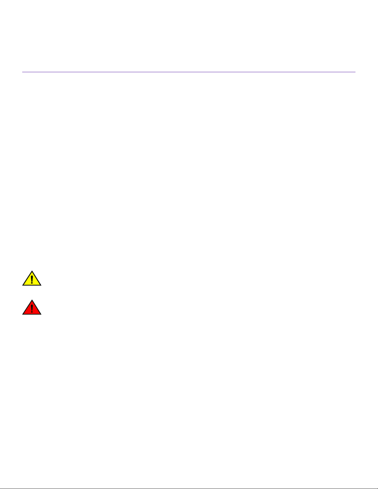
Device slot numbering: port-side
The ExtremeRouting SLX 9850-4 contains 4 slots for interface modules. Each slot is 1.5 rack units (RUs) in height. A maximum of 4
interface modules is supported per chassis.
The serial number for the device is located at the top of the chassis.
The following
the numbering of each router component in the chassis when you enter the show slots command.
For a list and description of management module ports, refer to Front panel and port description on page 87. For a list and description
of interface module ports, refer to Front panel and port description on page 95.
gure shows the device slot numbering and port side view of the SLX 9850-4. The call-outs in the gure correspond to
ExtremeRouting SLX 9850-4 Hardware Installation Guide
9035474-02 Rev AA 17
Device slot numbering: nonport-side
FIGURE 1 Port side of the SLX 9850-4
1. Interface module slot 1
2. Interface module slot 2
3. Interface module slot 3
4. Interface module slot 4
5. Management module slot 1
6. Management module slot 2
7. Power supply slot 1
8. Power supply slot 2
9. Power supply slot 3
10. Power supply slot 4
11. Power supply slot 5
12. Power supply slot 6
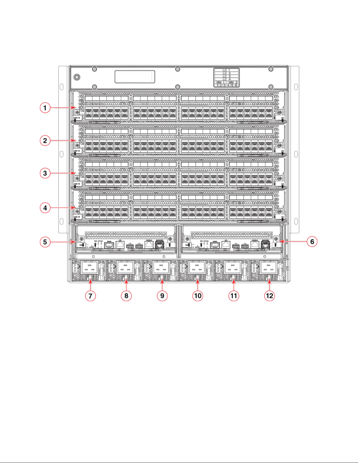
Device slot numbering: nonport-side
The following
modules when you enter the show slots command.
18 9035474-02 Rev AA
gure shows the nonport-side view of the SLX 9850-4. The callouts in the gure correspond to the numbering of the fan
ExtremeRouting SLX 9850-4 Hardware Installation Guide
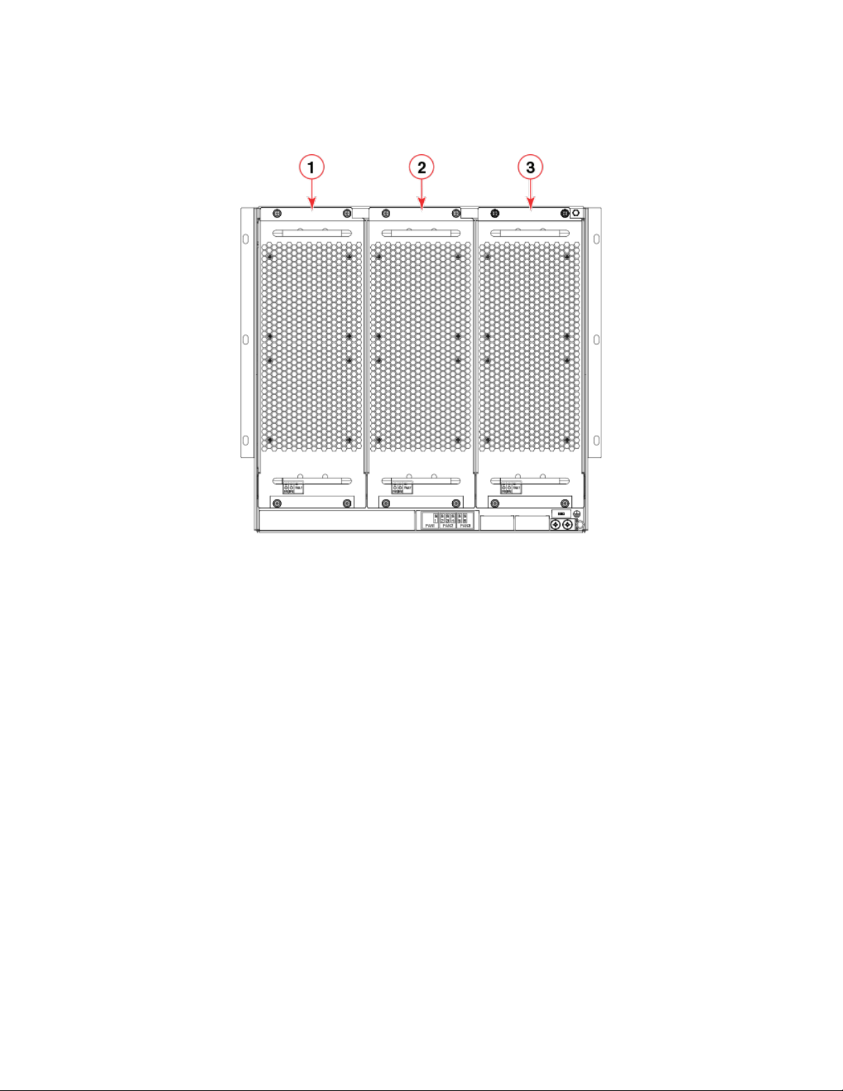
FIGURE 2 Nonport side of the SLX 9850-4
Device slot numbering: nonport-side
1. Fan module 1
2. Fan module 2
3. Fan module 3
The switch fabric modules are located behind the fans. There are six slots for the switch fabric modules. Numbering for the modules
goes from left to right, with 1 on the far left and 6 on the far right.
ExtremeRouting SLX 9850-4 Hardware Installation Guide
9035474-02 Rev AA 19
Device management options
FIGURE 3 Switch Fabric Modules shown with fans removed for the SLX 9850-4
1. SFM 1
2. SFM 2
3. SFM 3
4. SFM 4
5. SFM 5
6. SFM 6
Device management options
Use the serial ports to manage your device. The serial ports are located on the management module. The following gure shows the
serial console ports. Use the console port for device management.
20 9035474-02 Rev AA
ExtremeRouting SLX 9850-4 Hardware Installation Guide
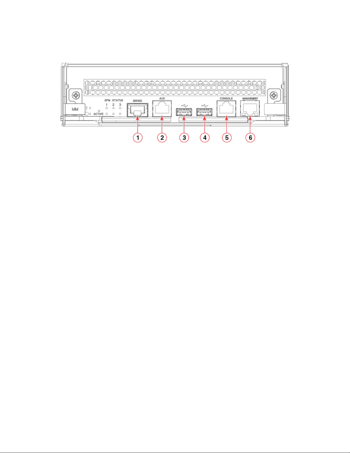
FIGURE 4 Management module front panel
Device management options
1. Service Ethernet port, 10G/1G/100M
2. Auxiliary console port
3. USB port
4. USB port
5. Console port
6. Management Ethernet port, 1G/100M/10M
ExtremeRouting SLX 9850-4 Hardware Installation Guide
9035474-02 Rev AA 21

22 9035474-02 Rev AA
ExtremeRouting SLX 9850-4 Hardware Installation Guide
Preparing for the Installation
• Safety precautions.............................................................................................................................................................................................23
• Facility requirements ....................................................................................................................................................................................... 24
• Time and items required for installation...................................................................................................................................................25
• Quick installation checklists...........................................................................................................................................................................26
• Unpacking the shipping carton....................................................................................................................................................................28
• Shipping carton contents................................................................................................................................................................................29
Safety precautions
When using this product, observe all danger, caution, and attention notices in this manual. The safety notices are accompanied by
symbols that represent the severity of the safety condition
Refer to Cautions and Danger Notices on page 151 at the end of this guide for translations of safety notices for this product.
General precautions
DANGER
The procedures in this manual are for qualied service personnel.
DANGER
Before beginning the installation, see the precautions in “Power precautions.”
CAUTION
Changes or modications made to this device that are not expressly approved by the party responsible for compliance
could void the user's authority to operate the equipment.
CAUTION
Disassembling any part of the power supply and fan assembly voids the warranty and regulatory certications. There are no
user-serviceable parts inside the power supply and fan assembly.
CAUTION
Make sure the airow around the front, and back of the device is not
restricted.
CAUTION
Never leave tools inside the chassis.
CAUTION
Use the screws specied in the procedure. Using longer screws can damage the
device.
ESD precautions
DANGER
For safety reasons, the ESD wrist strap should contain a series 1 megaohm resistor.
ExtremeRouting SLX 9850-4 Hardware Installation Guide
9035474-02 Rev AA 23
Facility requirements
Lifting precautions
DANGER
Use safe lifting practices when moving the product.
DANGER
A fully populated ExtremeRouting SLX 9850-4 weighs approximately 137.4 kg (303 lb) and requires a hydraulic or
assisted lift to install it.
Laser precautions
DANGER
All ber-optic interfaces use Class 1 lasers.
DANGER
Laser Radiation. Do Not View Directly with Optical Instruments. Class 1M Laser Products.
DANGER
Use only optical transceivers that are qualied by Extreme Networks, Inc. and comply with the FDA Class 1 radiation
performance requirements dened in 21 CFR Subchapter I, and with IEC 60825 and EN60825. Optical products that do
not comply with these standards might emit light that is hazardous to the eyes.
Facility requirements
Before installing the device, be sure the following facility requirements are met.
TABLE 14 Facility requirements
Type Requirements
Device specications Ensure that the facility can accommodate system, power, and environmental specications for this device as
outlined in the ExtremeRouting SLX 9850 Technical Specications on page 137 .
Electrical Ensure that there are dedicated electrical branch circuits with the following characteristics:
• Protected by a circuit breaker in accordance with local electrical codes
• Supply circuit, line fusing, and wire size adequate to the electrical rating on the chassis nameplate
• Location close to the chassis and easily accessible
• Grounded outlets installed by a licensed electrician and compatible with the power cords
Thermal Ensure that the air intake and exhaust vents have a minimum of 5.1 cm (2 in.) of airspace.
Ensure that the air temperature on the air intake side is less than 40°C (104°F) during operation.
Rack Plan to install the device with the port side facing the air-intake aisle.
Ensure that the following amount of space is available in the rack:
• SLX 9850-4: 10 rack unit (RU) height x 17.22 inches (43.7 cm) width x 30 inches (76.2 cm) depth.
Ensure that the rack meets these additional requirements:
• All equipment in the rack is grounded through a reliable branch circuit connection.
• Additional weight of chassis will not exceed the rack’s weight limits
• The rack is secured to ensure stability in case of unexpected movement.
24 9035474-02 Rev AA
ExtremeRouting SLX 9850-4 Hardware Installation Guide

Time and items required for installation
NOTE
This device is suitable for connection to the Central Oce and where NEC requirements apply. Additionally, it may be installed
in either a Common Bonding Network (CBN) or Isolated Bonding Network (IBN).
Time and items required for installation
You can set up and install the device in either a two- or four-post rack. Refer to Supported hardware and software on page 11 for
applicable rack mount kits.
The following table describes the main installation and setup tasks and the estimated time required for each, and the items required to
complete the task for a device.
These time estimates assume a prepared installation site and appropriate power and network connectivity.
TABLE 15 Installation tasks, time, and items required
Installation task Time estimate Items required
Site preparation and unpacking the device 30 minutes #2 Phillips screwdriver.
Pallet jack.
Tinsnips or strapping cutter (used to cut carton
straps).
Hydraulic lift or assisted lift, able to raise to a
minimum of 140 cm (55 in.), with a minimum
capacity of 212 lb (96.2 kg) for the SLX
9850-4 Router
To know the weight of your device fully
populated with the required interface modules,
refer to the ExtremeRouting SLX 9850
Technical Specications on page 137 .
Installing rack mount kit 30 minutes Refer to instructions in Mounting the Device on
page 31.
Mounting and securing the device in the rack 30 minutes Refer to instructions in Mounting the Device on
page 31.
Installing power cables and powering on the
device
Establishing serial connection, logging in to the
device, and conguring IP addresses
Installing an Ethernet cable, opening a Telnet
session, and conguring the device domain ID,
date and time, and additional system
parameters. Verify and back up the
conguration.
20 minutes Use the power cables provided in the device
accessories kit.
Refer to instructions in Providing power to the
device on page 58.
20 minutes Requires the following items:
• Serial cable provided in the accessory
kit.
• Workstation computer with a serial
port or terminal server port and a
terminal emulator application (such as
HyperTerminal).
• Ethernet IP address for the device.
20 minutes Ethernet cabling (optional) for Telnet access.
Refer to Initial Setup and Verication on page
57 for more information.
ExtremeRouting SLX 9850-4 Hardware Installation Guide
9035474-02 Rev AA 25

Quick installation checklists
TABLE 15 Installation tasks, time, and items required (continued)
Installation task Time estimate Items required
Installing transceivers as needed 30-60 minutes SFP+ and QSFP28 optical transceivers as
needed. Requires the following optics:
• SFP+ optics for 72-port 10GbE/
1GbE interface module
• QSFP28 for 36-port 100GbE, 60port 40GbE, or 240-port 10GbE
ex-speed interface module
Attaching ber-optic cables, cable ties, and cable
guides
2-3 hours Fiber optic cables, cable ties.
If 10 GbE speed is used for the 36-port 100
GbE, 60-port 40 GbE, or 240-port 10GbE
ex-speed interface module, 40 GbE-to-10
GbE breakouts are required.
Quick installation checklists
This checklists provide a high-level overview of the basic installation process from the planning stage to the point where the device
comes online and is ready to be deployed. Completing all the tasks in the suggested order ensures successful installation. Extreme
recommends that you print this checklists and take them to the installation site.
Pre-installation tasks
Review all installation requirements ahead of time as part of your site preparation. Careful planning and site preparation ensures seamless
installation, especially when installing multiple devices.
TABLE 16 Installation prerequisites
Task Task details or additional information Completed
Unpack the device. Unpack the device as shown in the Unpacking the shipping carton on page 28 .
Take an inventory of the hardware components included in your shipment. Refer to
Supported hardware and software on page 11 .
Gather necessary components and
required tools.
Review the safety precautions. Refer to Safety precautions on page 23. For translations, refer to Cautions and Danger
Plan the installation. Prepare space in your rack for the device and obtain the appropriate rack mount kit. Refer
Review and verify installation requirements. Verify that the following requirements are met. Refer to Facility requirements on page 24
Gather network conguration parameters.
Review the time and items required information at the beginning of each chapter to
ensure you have gathered all necessary components required for the following installation
tasks:
• Mounting the Device on page 31
• Inserting an interface module on page 97
Notices on page 151.
to Mounting options on page 31.
for everything but the environmental requirements, which are found in the Environmental
Requirements section in ExtremeRouting SLX 9850 Technical Specications on page
137.
• Electrical
• Environmental
• Rack
• Thermal
• IP address:
26 9035474-02 Rev AA
ExtremeRouting SLX 9850-4 Hardware Installation Guide

Quick installation checklists
TABLE 16 Installation prerequisites (continued)
Task Task details or additional information Completed
• Subnet mask:
• Default gateway:
• Domain ID:
• Time zone:
Installation and initial conguration
The initial setup includes mounting the device in a rack and completing the conguration tasks necessary to bring the device online and
verify the operation.
TABLE 17 Installation and basic system
Task Task details or additional information Completed
Mount the device. Choose the two-post or the four-post rack mounting option. Refer to Mounting options
Install the interface modules, power supply
modules, switch fabric modules, and fan
modules.
Gather all components required for the initial
setup.
Provide power to the device. Refer to Providing power to the device on page 58.
Attach a management station, establish a
serial connection, and change the default
passwords (optional).
Set the IP address, subnet mask, and the
default gateway IP address.
Establish an Ethernet connection. By establishing an Ethernet connection, you can complete the device conguration
Customize the chassis and host names. Use the switch-attributes chassis-name and switch-attributes host-name commands
Set the date and time.
Optional: Congure the DNS service. Use the ip dns domain-name and, if required, ip dns name-server commands to create
Verify that the device operates correctly.
conguration
on page 31 .
Refer to Inserting an interface module on page 97, Inserting an AC power supply
module on page 108, Inserting a switch fabric module on page 122, and Inserting a
fan module on page 117.
Refer to Inserting an interface module on page 97, Inserting an AC power supply
module on page 108 or Inserting a DC power supply module on page 109, Inserting a
switch fabric module on page 122, and Inserting a fan module on page 117.
Refer to Initial Setup and Verication on page 57.
Refer to Establishing a serial connection on page 63. After completing this task, log in
to the serial port to congure the device.
Use the chassis virtual-ip or chassis virtual-ipv6 command to congure an IP address.
For more information, refer to Conguring a static IP address on page 66.
using a serial or Telnet session. Refer to Establishing an Ethernet connection on page
68 for more information.
to change the default router name. For more information, refer to the Customizing the
chassis and host names on page 69
• Use the clock set command to set the date and time.
• Use the clock timezone command to set the time zone.
• After you congure the system time, use commands in NTP conguration
mode to synchronize the time with an external NTP server.
Refer to Setting the date and time on page 70 for more information. For detailed
command information, refer to the Extreme SLX-OS Management Conguration Guide
for the SLX 9850 Router .
DNS server entries. Refer to the Extreme SLX-OS Security Conguration Guide for the
SLX 9850 Router for more information.
• Check the LEDs to verify operation of module components in the device.
Refer to Interpreting management module LEDs on page 75, Interpreting
interface module LEDs on page 77, Interpreting power supply module
LEDs on page 80, Interpreting fan module LEDs on page 83, and
Interpreting switch fabric module LEDs on page 84.
ExtremeRouting SLX 9850-4 Hardware Installation Guide
9035474-02 Rev AA 27

Unpacking the shipping carton
TABLE 17 Installation and basic system conguration (continued)
Task Task details or additional information Completed
• The following commands can be useful to establish an operational baseline
for the device. Refer to the Extreme SLX-OS Monitoring Conguration Guide
for the SLX 9850 Router for more information about the following
commands:
– show chassis
– show system
– show slots
– show linecard
– show environment fan
– show environment power
– show environment sensor
– show environment temp
Back up the conguration. Use the copy running-cong command to copy the running conguration to the startup
conguration. Refer to the Backing up the conguration on page 73 for more
information about this command.
Optional: Power o the devices. Disconnect all power cords to the power supplies or switch o the rack power source.
Refer to Powering down the device on page 73 for more information.
Unpacking the shipping carton
Use the following procedure to unpack and install your device. The device is packaged in a cardboard box with foam packing on a
wooden pallet.
1. Cut the bands that encircle the packing carton.
a) Unpack the device
b) Leave the device on top of the shipping tray and pallet if the device must be transported to the installation location.
2. Slide the upper portion of the cardboard shipping box up o the pallet and shipping tray.
NOTE
Save the packing materials in the event you need to return the product.
3. Remove the two cardboard inner walls from the sides of the package.
4. Remove the accessory tray that is in the center of the upper foam packing.
The tray is in an oblong cardboard box.
5. Remove the upper foam packing.
6. Remove the front and rear foam pieces from the sides of the device.
7. Use a pallet jack or other assisted lift to transport the device to the installation area.
NOTE
When removing the device from the packaging, be careful to not damage the ground lug that is located at the bottom
rear of the device.
8. Place the device so that the port side (front) has access to intake air.
28 9035474-02 Rev AA
ExtremeRouting SLX 9850-4 Hardware Installation Guide

Shipping carton contents
Shipping carton contents
When unpacking the device, follow the procedures in Unpacking the shipping carton on page 28. Verify that the contents of the shipping
carton are complete. Save the shipping carton and packaging in the event you need to return the shipment.
• The SLX 9850 device with shipping tray
NOTE
The interface modules are packaged separately while the switch fabric modules are shipped inside the chassis
• Packing foam
• Antistatic plastic
• An accessory kit containing the following items:
– A serial cable
– ESD wrist strap
– SFP extraction tool
– Cable management kit
– China-RoHS Hazardous/Toxic Substance statement
– Extreme documentation web pointer card
– Power Cord Retainer Kit
NOTE
Power cords are not included.
NOTE
Rack mount kit is not included.
ExtremeRouting SLX 9850-4 Hardware Installation Guide
9035474-02 Rev AA 29

30 9035474-02 Rev AA
ExtremeRouting SLX 9850-4 Hardware Installation Guide
 Loading...