

Extreme Networks ExtremeControl IA-A-305, ExtremeControl IA-A-25 Installation Manual

®
ExtremeControl
IA-A-305 Installation
Guide
8/2019
9036407-00
Subject to Change Without Notice
Copyright © 2019 Extreme Networks, Inc. All Rights Reserved.
1 of 31

Legal Notices
Extreme Networks, Inc., on behalf of or through its wholly-owned subsidiary,
Enterasys Networks, Inc., reserves the right to make changes in specifications
and other information contained in this document and its website without prior
notice. The reader should in all cases consult representatives of Extreme
Networks to determine whether any such changes have been made.
The hardware, firmware, software or any specifications described or referred to
in this document are subject to change without notice.
Trademarks
Extreme Networks and the Extreme Networks logo are trademarks or registered
trademarks of Extreme Networks, Inc. in the United States and/or other
countries.
All other names (including any product names) mentioned in this document are
the property of their respective owners and may be trademarks or registered
trademarks of their respective companies/owners.
For additional information on Extreme Networks trademarks, please see:
www.extremenetworks.com/company/legal/trademarks/
Contact
If you require assistance, contact Extreme Networks using one of the following
methods.
l Global Technical Assistance Center (GTAC) for Immediate Support
l Phone: 1-800-998-2408 (toll-free in U.S. and Canada) or 1-603-952-5000. For
the Extreme Networks support phone number in your country, visit:
www.extremenetworks.com/support/contact
l Email: support@extremenetworks.com. To expedite your message, enter the
product name or model number in the subject line.
l GTAC Knowledge — Get on-demand and tested resolutions from the GTAC
Knowledgebase, or create a help case if you need more guidance.
2 of 31

l The Hub — A forum for Extreme customers to connect with one another, get
questions answered, share ideas and feedback, and get problems solved. This
community is monitored by Extreme Networks employees, but is not intended to
replace specific guidance from GTAC.
l Support Portal — Manage cases, downloads, service contracts, product licensing,
and training and certifications.
3 of 31

Table of Contents
Table of Contents 4
About this Guide 6
Engine Overview and Setup 7
Kit Contents 7
Specifications 7
Front Panel Features 9
Hard Drive LED Indicator Patterns 10
Back Panel Features 10
Power Supply Status Indicator Patterns 11
Removing and Installing the Front Bezel 12
Removing the Front Bezel 12
Installing the Front Bezel 12
Installing the Engine into a Rack 12
Torque Values 13
Configuration 15
Pre-Configuration Tasks 15
Configuring the Engine 15
Changing Engine Settings 21
Using Extreme Management Center 21
Changing DNS, NTP, SSH, and SNMP Settings 21
Changing Hostname, Gateway, and Static Routes 22
Using the Engine CLI 23
Changing the Extreme Management Center Server IP Address 23
4 of 31

Changing Web Service Credentials 23
Changing the Engine IP Address and Basic Network Settings 23
Changing Date and Time Settings 24
Upgrading Engine Software 24
Reinstalling Engine Software 25
Product Regulatory and Compliance Information 27
Federal Communications Commission (FCC) Notice 27
Industry Canada, Class A 28
CE Notice 28
VCCI Notice 28
BSMI EMC Statement — Taiwan 28
Hazardous Substances 29
European Waste Electrical and Electronic Equipment (WEEE) Notice 29
Declaration of Conformity 31
5 of 31

About this Guide
This document describes the installation and initial configuration of the Extreme
Networks® Extreme Access Control IA–A–305 hardware engine.
This document is intended for experienced network administrators who are
responsible for implementing and maintaining communications networks.
6 of 31

Kit Contents
Engine Overview and Setup
This chapter lists the components shipped with the IA–A–305 engine, describes
the front and back panels, and provides information on engine specifications.
For complete regulatory compliance and safety information, refer to the
document Intel® Server Products Product Safety and Regulatory Compliance,
available at the following links:
http://download.intel.com/support/motherboards/server/sb/g23122003_
safetyregulatory.pdf
http://www.extremenetworks.com/support/documentation/
Kit Contents
The engine ships with the following components:
l Extreme Networks URL card
l Front bezel label
l A rack mounting kit
l Two rack handles and appropriate screws
l AC power cord bracket and cable clamp kit
l One USB flash drive
Specifications
The following tables list the physical and environmental specifications for the
engine.
IA-A-305 Physical Specifications
Processor
Processor type IA-A-305 - Intel® Xeon® E5-2620 v4 processor
Processor speed 2.1 GHz
CPU Cores 8
Memory
7 of 31

Specifications
Architecture 2400 MHz Dual Ranked Registered (RDIMM) ECC
DDR4
Memory module capacities 4 GB DIMMs
Minimum RAM (included) 32 GB (eight 4 GB DIMMs)
Maximum RAM 48 GB (twenty-four 2 GB RDIMMs)
Drives
Hard drives One 240 GB SSD hard drive
Connectors
Back
NIC Four RJ-45
Serial 9-pin, DTE, 16550-compatible
USB Three 4-pin, USB 2.0-compliant
Video 15-pin VGA
Networking Two 1 GB Ethernet
Front
USB Two 4-pin, USB 2.0-compliant
Video 15-pin VGA
Power
AC power supply (per power
Redundant power supply
supply)
Wattage 750 watts
Input voltage l 90 – 132 V at 47/63 Hz 8.2 A
l 180 – 264 V at 47/63 Hz 4.4 A
Output voltage l 62.0A at 12 V
l 2.1A at 12 VSB
Physical
Height 4.45 cm (1.72 in.)
Width 43.0 cm (16.93 in.)
Depth 70.99 cm (27.95 in.)
Weight (maximum configuration) 13.15 kg (29 lb.)
8 of 31
IA-A-305 Environmental Specifications
Parameter Limits
Front Panel Features
Operating
temperature
Storage
+10°C (+50°F) to +35°C (+95°F) with the maximum rate of change
not to exceed 10°C (+50°F) per hour
-40°C (-40°F) to +70°C (+158°F)
temperature
Storage humidity 50% to 90%, non-condensing at 28°C (82°F)
Vibration,
5 Hz to 500 Hz, 2.20 g RMS random
unpackaged
Shock, operating Half sine, 2 g-force peak, 11 milliseconds
Shock,
unpackaged
Trapezoidal, 25 g, velocity change 136 inches/second
(40 lb to < 80 lb)
Shock, packaged Non-palletized free fall in height 24 inches (40 lb to < 80 lb)
ESD ±12 KV except I/O port ±8 KV per Intel® Environmental test
specification
Estimated thermal
1550 BTU/Hr
dissipation
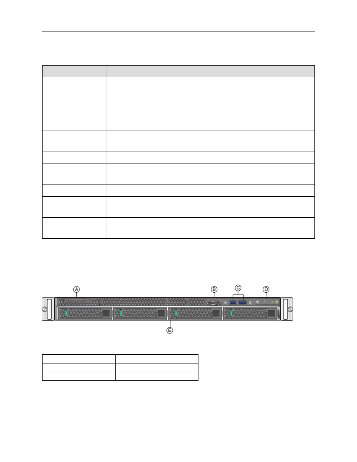
Front Panel Features
This section shows the front panel and describes the major features.
IA-A-305 Front Panel Features
A System labelpull-out D Front control panel(see figure below)
B Video Connector E Hard disk drive bays
C USB 3.0 Ports
9 of 31
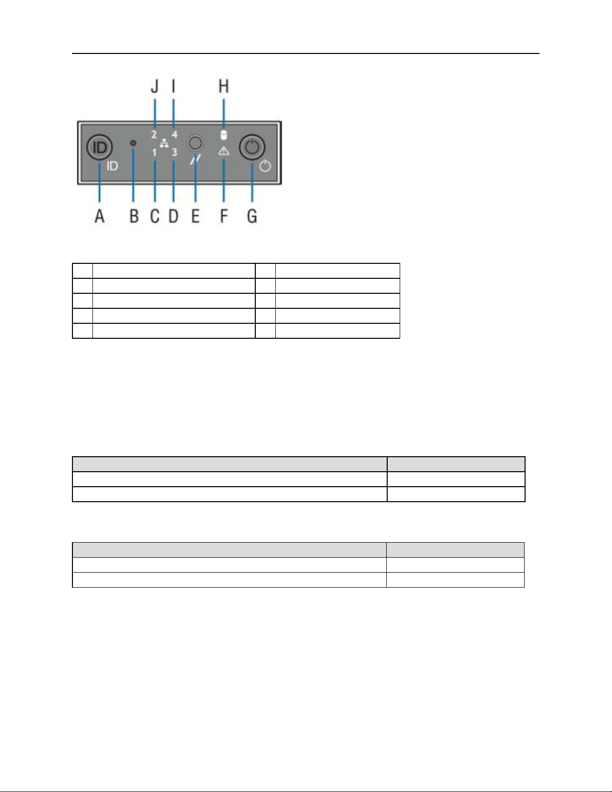
Front Control Panel
A System ID button w/integrated LED F System status LED
B NMI button (recessed, tool required for use) G Power button w/integrated LED
C Mgmt port activity LED H Hard drive activity LED
D Not us ed I Not used
E System cold reset button J Not used
Back Panel Features
Hard Drive LED Indicator Patterns
The hard drive has two LED indicators visible from the front of the system: one is
a green LED for disk activity, and the other is amber and indicates hard drive
status. The following tables describe the LED states.
Hard Drive Activity LED Indicator Patterns
Hard Drive Condition Activity LED Patterns
Power on and drivespinning up or spinning down Off
Power on with drive activity Blinking green
Hard Drive Status LED Indicator Patterns
Hard Drive Condition Status LED Patterns
No access or no fault Off
Hard drive fault has occurred Solid amber
Back Panel Features
This section shows the back panel and describes the major features.
10 of 31
 Loading...