

Extreme Networks ExtremeCloud Appliance Series, ExtremeCloud Appliance E2120, ExtremeCloud Appliance E1120, ExtremeCloud Appliance E3120 User Manual

ExtremeCloud Appliance User
Guide
Version 4.36.03
9036135-02
Published June 2019

Copyright © 2019 Extreme Networks, Inc. All rights reserved.
Legal Notice
Extreme Networks, Inc. reserves the right to make changes in specifications and other information
contained in this document and its website without prior notice. The reader should in all cases
consult representatives of Extreme Networks to determine whether any such changes have been
made.
The hardware, firmware, software or any specifications described or referred to in this document
are subject to change without notice.
Trademarks
Extreme Networks and the Extreme Networks logo are trademarks or registered trademarks of
Extreme Networks, Inc. in the United States and/or other countries.
All other names (including any product names) mentioned in this document are the property of
their respective owners and may be trademarks or registered trademarks of their respective
companies/owners.
For additional information on Extreme Networks trademarks, please see:
www.extremenetworks.com/company/legal/trademarks
Open Source Declarations
Some software files have been licensed under certain open source or third-party licenses. Enduser license agreements and open source declarations can be found at:
www.extremenetworks.com/support/policies/software-licensing

Table of Contents
Preface................................................................................................................................................................................................ 5
Conventions.............................................................................................................................................................................5
Documentation and Training...........................................................................................................................................6
Providing Feedback to Us................................................................................................................................................ 6
Getting Help............................................................................................................................................................................ 6
AP Regulatory Information...............................................................................................................................................7
Chapter 1: Welcome to ExtremeCloud Appliance.................................................................8
The Appliance.........................................................................................................................................................................8
Wireless AP Overview.........................................................................................................................................................9
Sites Overview......................................................................................................................................................................10
Navigating the User Interface........................................................................................................................................18
Hierarchical Visibility for WiNG Appliances.......................................................................................................... 20
Chapter 2: Dashboard..............................................................................................................22
Overview Dashboard........................................................................................................................................................ 22
Chapter 3: Monitor...................................................................................................................27
Sites List..................................................................................................................................................................................27
Device List.............................................................................................................................................................................40
Networks List........................................................................................................................................................................52
Clients.......................................................................................................................................................................................53
Policy........................................................................................................................................................................................ 58
Chapter 4: Configure...............................................................................................................63
Network Configuration Steps.......................................................................................................................................63
Sites.......................................................................................................................................................................................... 64
Devices...................................................................................................................................................................................105
Networks................................................................................................................................................................................ 118
Policy.......................................................................................................................................................................................127
AP Adoption Rules...........................................................................................................................................................142
Chapter 5: Onboard............................................................................................................... 145
AAA Authentication........................................................................................................................................................145
Managing Captive Portal...............................................................................................................................................154
Managing Access Control Groups............................................................................................................................ 165
Access Control Rules...................................................................................................................................................... 168
Chapter 6: Tools......................................................................................................................173
Workflow............................................................................................................................................................................... 173
Logs......................................................................................................................................................................................... 182
Diagnostics...........................................................................................................................................................................185
Chapter 7: Administration..................................................................................................... 187
System Configuration......................................................................................................................................................187
Managing Administrator Accounts.........................................................................................................................205
ExtremeCloud Appliance Applications.................................................................................................................206
Licensing............................................................................................................................................................................... 210
Glossary..........................................................................................................................................215
ExtremeCloud Appliance User Guide for version 4.36.03 3

Table of Contents
Index.........................................................................................................................................217
ExtremeCloud Appliance User Guide for version 4.36.03 4
Preface
This section discusses the conventions used in this guide, ways to provide feedback, additional help, and
other Extreme Networks® publications.
Conventions
This section discusses the conventions used in this guide.
Text Conventions
The following tables list text conventions that are used throughout this guide.
Table 1: Notice Icons
Icon Notice Type Alerts you to...
General Notice Helpful tips and notices for using the product.
Note Important features or instructions.
Caution Risk of personal injury, system damage, or loss of data.
Warning Risk of severe personal injury.
New!
New Content Displayed next to new content. This is searchable text within the PDF.
Table 2: Text Conventions
Convention Description
Screen displays
The words enter and
type
[Key] names Key names are written with brackets, such as [Return] or [Esc]. If you must press two
Words in italicized type Italics emphasize a point or denote new terms at the place where they are defined in
This typeface indicates command syntax, or represents information as it appears on the
screen.
When you see the word “enter” in this guide, you must type something, and then press
the Return or Enter key. Do not press the Return or Enter key when an instruction
simply says “type.”
or more keys simultaneously, the key names are linked with a plus sign (+). Example:
Press [Ctrl]+[Alt]+[Del]
the text. Italics are also used when referring to publication titles.
ExtremeCloud Appliance User Guide for version 4.36.03 5

Documentation and Training
To find Extreme Networks product guides, visit our documentation pages at:
Current Product Documentation www.extremenetworks.com/documentation/
Archived Documentation (for earlier
versions and legacy products)
Release Notes www.extremenetworks.com/support/release-notes
Hardware/Software Compatibility Matrices https://www.extremenetworks.com/support/compatibility-matrices/
White papers, data sheets, case studies,
and other product resources
www.extremenetworks.com/support/documentation-archives/
https://www.extremenetworks.com/resources/
Training
Extreme Networks oers product training courses, both online and in person, as well as specialized
certifications. For more information, visit www.extremenetworks.com/education/.
Providing Feedback to Us
Quality is our first concern at Extreme Networks, and we have made every eort to ensure the accuracy
and completeness of this document. We are always striving to improve our documentation and help
you work better, so we want to hear from you! We welcome all feedback but especially want to know
about:
Content errors or confusing or conflicting information.
•
Ideas for improvements to our documentation so you can find the information you need faster.
•
Broken links or usability issues.
•
If you would like to provide feedback to the Extreme Networks Information Development team, you can
do so in two ways:
Use our short online feedback form at https://www.extremenetworks.com/documentation-
•
feedback/.
Email us at documentation@extremenetworks.com.
•
Please provide the publication title, part number, and as much detail as possible, including the topic
heading and page number if applicable, as well as your suggestions for improvement.
Getting Help
If you require assistance, contact Extreme Networks using one of the following methods:
Extreme
Portal
The Hub A forum for Extreme Networks customers to connect with one another, answer questions, and
Call GTAC For immediate support: 1-800-998-2408 (toll-free in U.S. and Canada) or +1 408-579-2826. For
Search the GTAC (Global Technical Assistance Center) knowledge base, manage support cases
and service contracts, download software, and obtain product licensing, training, and
certifications.
share ideas and feedback. This community is monitored by Extreme Networks employees, but is
not intended to replace specific guidance from GTAC.
the support phone number in your country, visit: www.extremenetworks.com/support/contact
ExtremeCloud Appliance User Guide for version 4.36.03 6

Before contacting Extreme Networks for technical support, have the following information ready:
Your Extreme Networks service contract number and/or serial numbers for all involved Extreme
•
Networks products
A description of the failure
•
A description of any action(s) already taken to resolve the problem
•
A description of your network environment (such as layout, cable type, other relevant environmental
•
information)
Network load at the time of trouble (if known)
•
The device history (for example, if you have returned the device before, or if this is a recurring
•
problem)
Any related RMA (Return Material Authorization) numbers
•
Subscribing to Service Notifications
You can subscribe to email notifications for product and software release announcements, Vulnerability
Notices, and Service Notifications.
1 Go to www.extremenetworks.com/support/service-notification-form.
2 Complete the form with your information (all fields are required).
3 Select the products for which you would like to receive notifications.
Note
You can modify your product selections or unsubscribe at any time.
4 Click Submit.
AP Regulatory Information
For regulatory information for the ExtremeCloud Appliance supported access point models and
appliances, refer to the appropriate Installation Guide.
ExtremeCloud Appliance User Guide for version 4.36.03 7

1 Welcome to ExtremeCloud
Appliance
The Appliance
Wireless AP Overview
Sites Overview
Navigating the User Interface
Hierarchical Visibility for WiNG Appliances
ExtremeCloud Appliance oers a streamlined customer experience with a common platform and
operating system across multiple Extreme Networks products. Get the power of ExtremeWireless and
Extreme Management Center with the flexibility of ExtremeCloud in one easy-to-use platform.
ExtremeCloud Appliance oers the following features:
Integrated Access Control
•
Integrated Maps
•
Historical data charts
•
Programmable REST API
•
On-premise standalone deployment with integration into ExtremeCloud/Extreme Management
•
Center and on-premise services
Clustered support for load sharing and resilience.
•
The Appliance
The appliance is a network device designed to integrate with an existing wired Local Area Network
(LAN). The ExtremeCloud Appliance provides both distributed and centralized management, network
access, and routing to wireless devices that use Wireless APs to access the network.
The appliance provides the following functionality:
Controls and configures wireless APs, providing distributed or centralized management.
•
Authenticates wireless devices that contact a wireless AP.
•
Assigns each wireless device to a network service when it connects.
•
Routes trac from wireless devices, using a network service, to the wired network.
•
Applies filtering roles to the wireless device session.
•
Provides session logging and accounting capability.
•
Manages switches.
•
ExtremeCloud Appliance supports the use of both a virtual appliance and a physical appliance.
Related Links
Appliance Product Family on page 9
ExtremeCloud Appliance User Guide for version 4.36.03 8

Welcome to ExtremeCloud Appliance
Appliance Product Family
ExtremeCloud Appliance supports the VE6120 virtual appliance and the following hardware appliances:
E1120
•
E2120
•
E3120
•
Wireless AP Overview
Extreme Networks APs use the 802.11 wireless standards (802.11a/b/g/n/ac/ax) for network
communications, and bridge network trac to an Ethernet LAN. In addition to the wireless APs that run
proprietary software and communicate with an appliance only, Extreme Networks oers a Cloudenabled AP. The AP39xx series are Cloud-enabled APs that inter-operate fully with ExtremeCloud™ and
other ExtremeWireless products.
The following ExtremeMobility™ AP5xx series APs are supported:
AP505i
•
AP510i/e
•
AP560i/h
•
The following ExtremeWireless™ AP39xx series APs are supported:
AP3917i/e/k
•
AP3916ic
•
AP3915i/e
•
AP3912i
•
AP3935i/e
•
AP3965i/e
•
The following ExtremeWireless WiNG™ APs are supported:
AP7522
•
AP7532
•
AP7562
•
AP7612
•
AP7632
•
AP7662
•
AP8432
•
AP8533
•
The Extreme Networks® Defender Adapter SA201 is supported.
A wireless AP physically connects to a LAN infrastructure and establishes an IP connection to
ExtremeCloud Appliance, which manages the AP configuration through the Wireless Assistant. The
appliance provides both distributed and centralized management (verification and upgrade) of the AP
firmware image.
ExtremeWireless AP39xx support a Centralized site. ExtremeWireless WiNG APs support a Distributed
site. The ExtremeMobility AP5xx support either a Centralized or Distributed site. The AP5xx support is
determined by the site type at discovery and registration.
ExtremeCloud Appliance User Guide for version 4.36.03 9

Welcome to ExtremeCloud Appliance
For a Centralized site using AP39xx or AP5xx access points, a UDP-based protocol enables
communication between an AP and ExtremeCloud Appliance. The UDP-based protocol encapsulates IP
trac from the AP and directs it to the appliance. The appliance decapsulates the packets and encrypts
(IPSec)[Default AP and appliance communication] and routes them to the appropriate destinations,
while managing sessions and applying roles.
For a Distributed site using AP76xx, AP8xxx, or AP5xx access points, the communication is handled
through the WebSocket protocol for configuration and through HTTPS POSTs for statistical data.
Sites Overview
Use sites to define boundaries for fast roaming and session mobility without interruption. A site
represents a physical, geographic area in your network, and defines a roaming domain. As the top-level
element in the ExtremeCloud Appliance data model, the site runs Sessions Manager and RF Manager
functions for all RF Domains in the site. Define the licensing domain for the site by selecting the Country
option, and define the AP platforms available to the site by selecting the site configuration, either
Distributed or Centralized.
A site in ExtremeCloud Appliance is composed of one or more device groups. Each device group holds
one or more APs. The APs in a device group must have the following in common:
AP Model
•
Configuration Profile
•
RF Domain
•
Regulatory domain and configuration type, which is defined at the site level.
•
A Centralized site can include multiple device groups all in a single RF domain, or multiple device
groups, each group in a unique RF domain. A Distributed site can only have a single RF domain.
A site also includes the following:
One or more floor plans. Floor plans are unique to each site.
•
Site metadata used to place the site on a Google map.
•
List of switches associated with the site.
•
Related Links
Centralized Site on page 10
Distributed Site on page 11
Adding a Site on page 64
Site Dashboard on page 27
Modifying Site Configuration on page 65
Site Location on page 67
Configuring Column Display on page 20
Centralized Site
A Centralized configuration uses ExtremeWireless AP models AP39xx, and AP5xx. Each Wireless AP
opens an IPSec tunnel to ExtremeCloud Appliance, and the Session Manager and RF Management
policy run on ExtremeCloud Appliance.
ExtremeCloud Appliance User Guide for version 4.36.03 10

Welcome to ExtremeCloud Appliance
A Centralized site topology allows seamless roaming within one geographic location. A single site
supports multiple device groups with a total of 200 to 4,000 APs [in appliance High Availability mode]
for the site. With a Centralized site, ExtremeCloud Appliance performs as the management server and
the session manager. The RF domain manager resides locally on ExtremeCloud Appliance.
Although session management is centralized at the appliance, users can select the best topology for
network access:
Bridged@AC (Tunneled for VLAN, attached at ExtremeCloud Appliance)
•
Bridged@AP
•
Fabric Attach (Bridge@AP with an I-SID mapping).
•
The following AP models can be deployed in a Centralized site:
AP505i
•
AP510i/e
•
AP560i/h
•
AP3917i/e/k
•
AP3916ic
•
AP3915i/e
•
AP3912i
•
AP3935i/e
•
AP3965i/e
•
Related Links
Use Case: Large Centralized Site on page 11
Use Case: Large Centralized Site
Scenario: A large centralized site is composed of two separate buildings. Each building supports a
unique configuration with its own policy requirements. Clients need the ability to roam between
buildings without session interruption.
Solution: Create a Centralized site, defining multiple device groups. Each device group will support a
unique profile configuration.
Distributed Site
A Distributed configuration uses ExtremeWireless WiNG APs. Each WiNG AP opens a WebSocket to
ExtremeCloud Appliance and Session Manager and Smart RF Manager run on one of the APs in the site.
All APs in a Distributed site have one RF Domain.
A Distributed site topology allows seamless roaming. Sites support multiple device groups with up to
200 APs associated with each site. With a Distributed site, ExtremeCloud Appliance performs as the
management server, and one AP has the elected role of session manager and RF domain manager.
Network trac is bridged locally at the AP, no trac forwarding back to ExtremeCloud Appliance.
The Fabric Connect network is supported by the AP, and switches can be managed from ExtremeCloud
Appliance over HTTP.
ExtremeCloud Appliance User Guide for version 4.36.03 11

Welcome to ExtremeCloud Appliance
The following AP models can be deployed in a Distributed site:
AP505i
•
AP510i/e
•
AP560i/h
•
AP7522
•
AP7532
•
AP7562
•
AP7612
•
AP7632
•
AP7662
•
AP8432
•
AP8533
•
Use Case: Distributed Site
Scenario: A site oers remote clinics with 10 APs each. This requires consistent configuration across all
clinics.
Solution: Create a separate site for each clinic location. Each site includes a unique device group. Create
one profile configuration and share the configuration Profile for all sites and device groups. Each site
represents a separate roaming domain using a single configuration Profile and a single RF Management
Profile.
Device Groups
The device group is composed of APs with the same model, configuration Profile, and RF Management
profile. The device group is defined within a site, so device groups within a site also share the
configuration type and licensing domain that is defined for the site.
If you have created a default device group for a specific AP model, upon discovery, the APs that match
that AP model are available on the Create Device Group dialog. Manually select each AP to add it to the
group. To automatically assign APs to a device group configure Adoption Rules before APs connect for
the first time.
If the device group is not yet created upon AP discovery, the AP is listed in the Access Points List with a
status of in-service trouble. After you create the device group and specify the configuration Profile for
that AP model, APs that match the configuration Profile are available on the Create Device Group
dialog. Manually select each AP to add it to the group.
Each device group contains the following elements:
AP devices included in the group. An AP can only be a member of one device group at a time. You
•
can manually move a device from one group to another.
A configuration Profile, which includes:
•
Networks
•
Roles
•
Radios
•
Wired Ports
•
ExtremeCloud Appliance User Guide for version 4.36.03 12
Air Defense integration parameters
•
ExtremeLocation integration parameters
•
RTLS
•
Profiles for Centralized APs support the following features:
•
IoT configuration
Positioning
Analytics
An RF Management policy.
•
Note
RF Management and configuration Profiles can be shared across device groups.
Note
Most AP radio properties depend on a regulatory domain; which is defined at the site level.
Devices that are connected to ExtremeCloud Appliance but not assigned to a device group
have the status of In-Service Trouble. Devices that have not discovered ExtremeCloud
Appliance have the status of Unknown.
Welcome to ExtremeCloud Appliance
Related Links
Adding Device Groups to a Site on page 67
Device Group Settings on page 67
AP Adoption Rules on page 142
Floor Plans on page 16
Site Parameters on page 65
Profiles
Configuration profiles in ExtremeCloud Appliance oer consistency and simplicity. Use a profile to
associate configuration parameters to a device group, and to apply configured network policy roles to
the group. You can associate a single profile to one or many device groups within a single site or across
multiple sites.
Profiles are used to configure APs and individual radios. The available configuration options depend on
the AP model. The full list of configuration settings are as follows:
Network configuration
•
Policy configuration
•
Radio settings
•
Port assignment
•
IoT configuration
•
AirDefense Service Platform (ADSP) integration
•
ExtremeLocation integration
•
Position Awareness configuration
•
Analytics
•
Real-Time Location System (RTLS) integration
•
ExtremeCloud Appliance User Guide for version 4.36.03 13
Welcome to ExtremeCloud Appliance
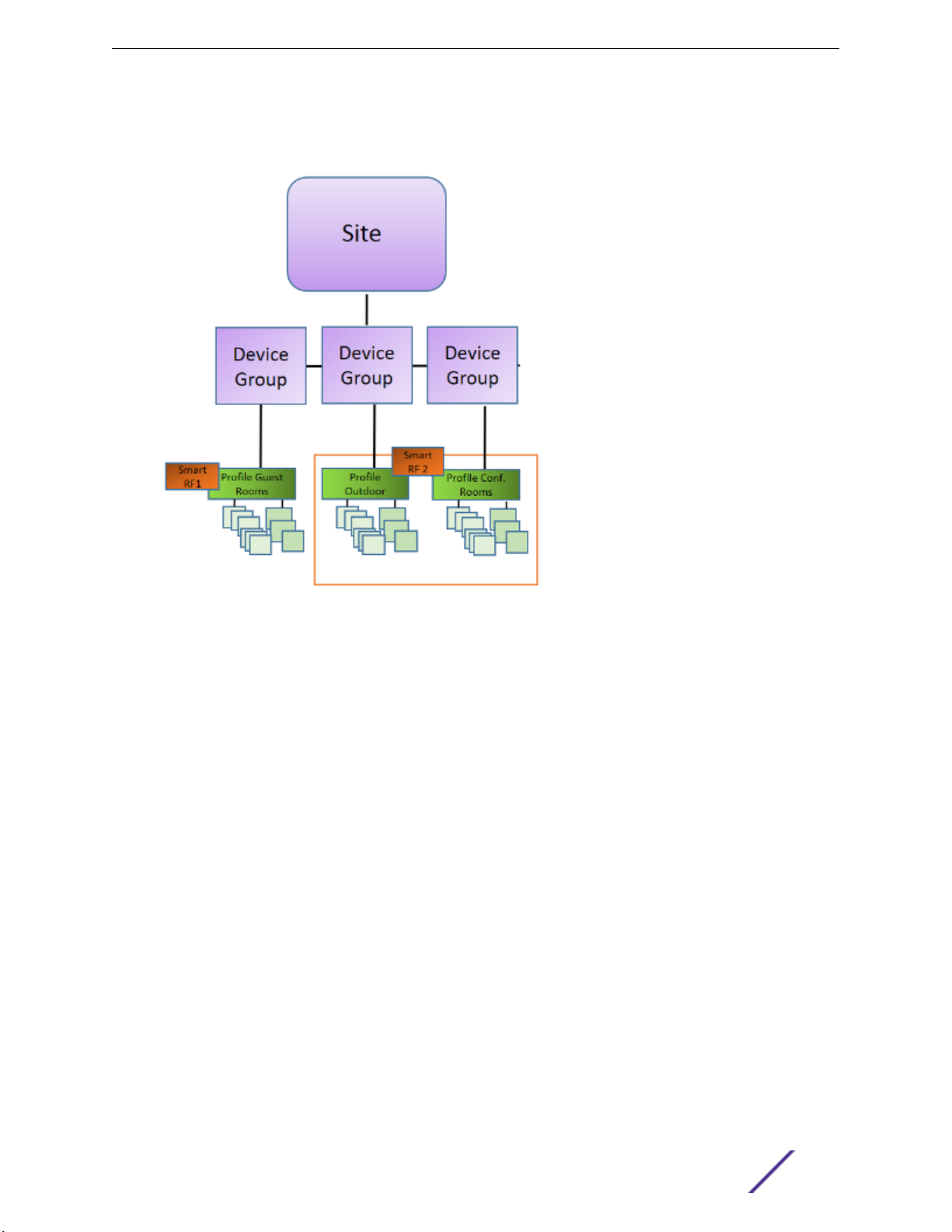
Figure 1 illustrates a single site, composed of multiple device groups, in dierent RF domains, using
unique configuration Profiles. This model oers seamless roaming between APs of all device groups.
Figure 1: Centralized Site Data Model: Unique Profile Per Device Group
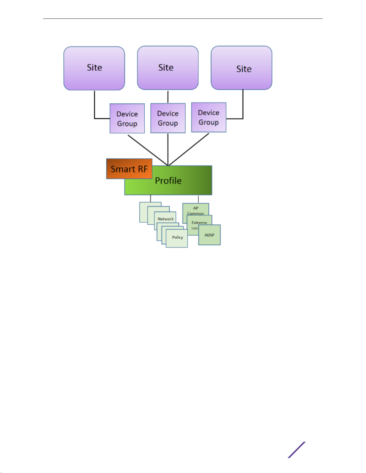
Figure 2 illustrates multiple sites with individual device groups, in one RF domain, sharing a common
configuration profile.
ExtremeCloud Appliance User Guide for version 4.36.03 14
Welcome to ExtremeCloud Appliance
Figure 2: Distributed Site Data Model: One Shared Profile
Related Links
Adding or Editing a Configuration Profile on page 68
RF Management on page 15
RF Management
Self Monitoring At Run Time (SMART) RF Management is designed to simplify RF configurations for
new deployments, while optimizing radio performance.
An RF policy can reduce deployment costs by scanning the RF environment to determine the best
channel and transmit power configuration for each radio, allowing APs to respond dynamically to
changing RF conditions. Apply RF Management policies to specific RF Domains.
After gathering information from the RF environment, RF Management makes intelligent configuration
choices. It monitors the network for external interference, neighbor interference, non-WiFi interference,
and client connectivity. It then intelligently applies algorithms determining optimal channel and power
selection for all APs in the network and constantly reacts to changes in the RF environment.
ExtremeCloud Appliance User Guide for version 4.36.03 15

Welcome to ExtremeCloud Appliance
Real-time network monitoring allows RF Management to provide self-healing functions, providing
automatic mitigation from potentially problematic events such as radio interference, non-WiFi
interference (noise), external WiFi interference, coverage holes, and radio failures. Self-healing is used to
enable a WLAN to better maintain wireless client performance and site coverage during dynamic RF
environment changes, which would otherwise require manual reconfiguration to resolve.
Related Links
Configuring RF Management on page 87
Configuring ACS RF Policy on page 90
Configuring Smart RF Policy on page 91
Floor Plans
Use Floor Plans to visualize a wireless deployment, plan device placement, and troubleshoot network
performance issues. The floor plan illustrates how the location of the AP aects network performance,
and illustrates AP location within a floor plan. Floor plans retrieve a list of all APs and associated clients
on the system with their current configurations. Use the floor plan to visualize AP performance based
on signal strength and channel assignment, and to verify network readiness within a floor plan. Floor
plan statistics are refreshed with a manual page refresh.
A floor plan is associated with the site. Work with floor plans under site configuration to import, export,
or configure a floor plan. View a configured floor plan from the Site dashboard page. You can also view
floor plans from the Client and Devices workbenches.
Toggle between floor plan Configuration and floor plan View:
From the floor plan View page, click Configure Site > Floor Plans to open the floor plan
•
Configuration page.
•
From the floor plan Configuration page, click
Related Links
Site Parameters on page 65
Configuring a Floor Plan on page 96
Floor Plan View on page 29
Positioning Profile Settings on page 85
Position Aware Services
Client location tracking is designed to manage a wireless environment and its resources. The Positioning
Engine works in conjunction with the ExtremeCloud Appliance floor plans to define specific areas for
Position Aware Services.
The Positioning Engine determines location based on measured Received Signal Strength (RSS) of the
client stations at the AP. The location algorithm uses RF fingerprinting based on a Path Loss model and
determines location by triangulating RSS reported from one or more APs.
to display the floor plan View.
Client Location Tracking is supported on AP39xx models only. Estimating location using readings from
multiple APs provides a more accurate location estimate. Estimating location using RSS from a single
AP is sucient to determine the location of client in terms of proximity to the associated AP. The client
location is indicated on the map with an icon that is representative of the specific client type. The
ExtremeCloud Appliance User Guide for version 4.36.03 16
Welcome to ExtremeCloud Appliance
Positioning Engine tracks location of multiple clients simultaneously and returns position relative to the
floor plan. The Positioning Engine can be configured to track associated users (active clients) or all
users.
Associated User. An associated user is an authenticated client. An associated user joins the SSID
•
provided by the AP by simply associating to the open or protected SSID. Positioning Engine can
track location for every associated client up to the ExtremeCloud Appliance model limit of
associated clients.
Un-Associated User. An unassociated user is a client that is not authenticated but is in the
•
designated area. Positioning Engine can track these clients.
Note
AP models AP76xx and AP8xxx support heat maps for Location Readiness but do not
support Foot Trac heat maps. Use ExtremeLocation integration for client tracking support
with these APs.
Related Links
Positioning Profile Settings on page 85
Position Aware Deployment on page 17
Position Aware Deployment
Deploying APs for location tracking requires additional consideration above the standard AP
deployment guidelines for coverage and capacity. The following are best practices for AP deployment:
Minimum Received RSS. No fewer than three APs should be detecting and reporting the RSS of any
•
client station. Only RSS readings stronger than -75 dBm are used by the Location Engine.
Use the same AP model for the entire floor plan.
•
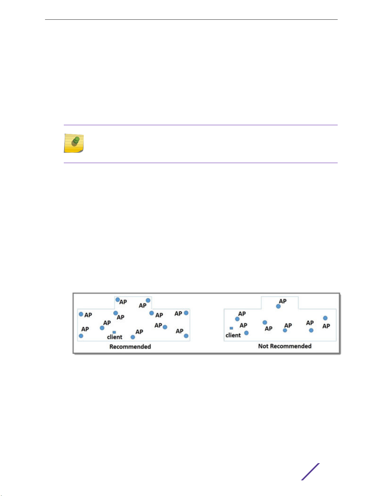
Design your floor plan with the APs installed at the corners of the floor plan, along the perimeter of
•
the location area. (An area is considered a closed polygon.) Do not cluster APs in the center of the
location area. The following illustration shows a recommended AP placement.
Figure 3: Recommended AP Placement
The maximum distance between APs depends on environmental factors such as the presence of
•
walls and structures, but as rule of thumb, in a location-aware deployment, place the APs 10 to 20
meters apart.
Install APs at the same height on the wall, and do not install APs behind walls or ceilings.
•
Install APs away from metal structures like poles or racks, because metal can aect the radiated
•
pattern.
Related Links
Position Aware Services on page 16
ExtremeCloud Appliance User Guide for version 4.36.03 17
Welcome to ExtremeCloud Appliance
Positioning Heatmaps on page 39
Placing Devices on page 103
Floor Plan Limits
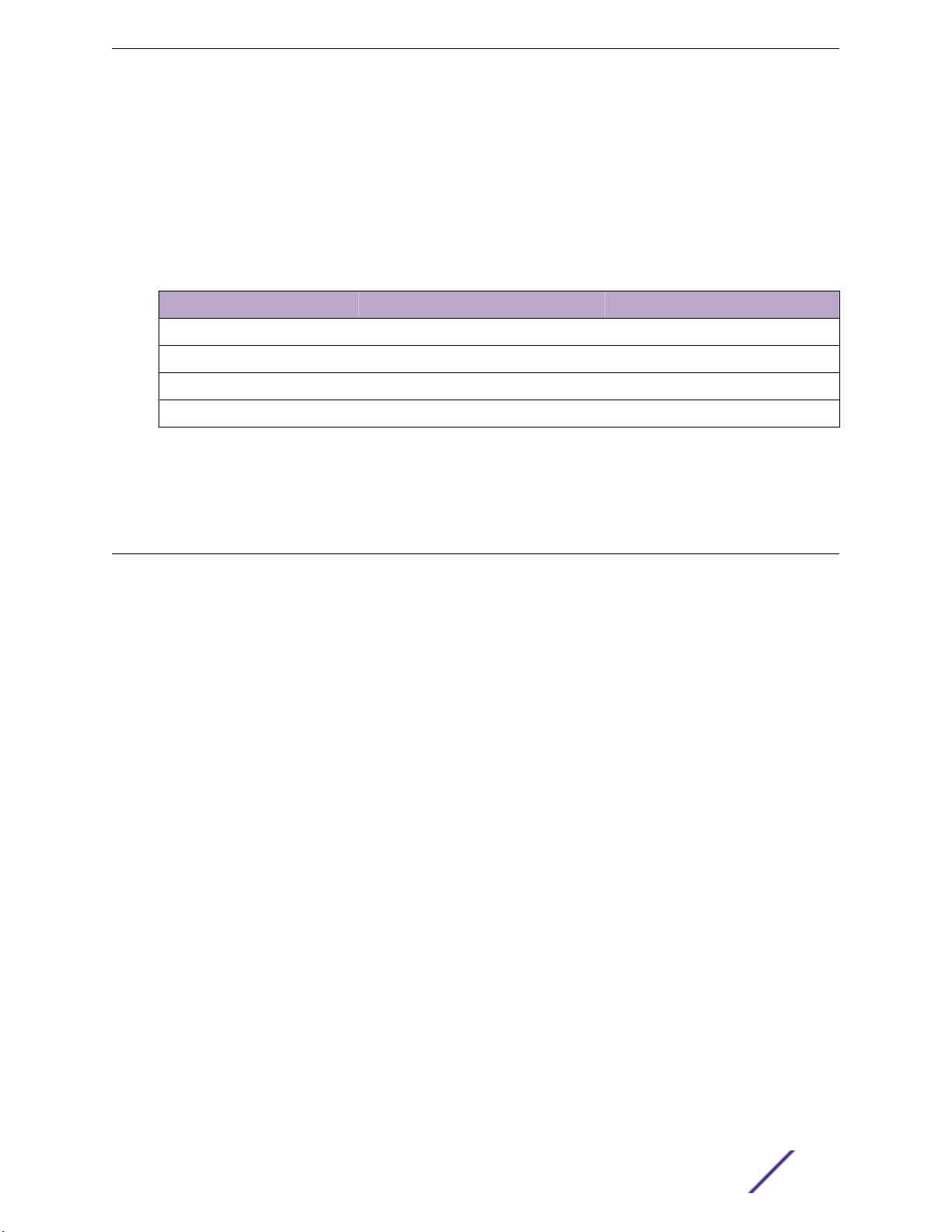
Table 3 outlines the floor plan limits for each type of ExtremeCloud Appliance appliance.
Table 3: Floor Plan Limit per Appliance
Appliance Maximum Floor Plan Limit Maximum Number of APs Per Floor
E1120 50 500
E2120 400 1,000
E3120 1,000 1,000
VE6120 200 1,000
Related Links
Floor Plans on page 16
Navigating the User Interface
The ExtremeCloud Appliance user interface is divided into workbenches that correspond to the network
administration workflow. Monitor your network from the Monitor workbench and configure network
settings from the Configure workbench.
ExtremeCloud Appliance sites are the building blocks on which your network configuration is based.
Start with Configure > Sites and work your way down the Configure workbench as you configure your
network.
The Dashboard is the first workbench. Once the network is up and running, use the Dashboard and
Monitor workbenches to monitor your network activity and performance.
The ExtremeCloud Appliance user interface can be accessed using the HTTPS protocol on the TCP port
5825. For example, if your ExtremeCloud Appliance has the IP address, 192.168.10.10, you can manage it
in a browser by typing https://192.168.10.10:5825/ into the URL field.
The factory preset credentials are Username: "admin", Password: "abc123". These values are casesensitive.
ExtremeCloud Appliance oers the following workbenches:
Dashboard
Monitor Monitor the following network components:
Monitor your network activity and performance on the Overview dashboard.
Sites
•
Devices
•
Networks
•
Clients
•
Policy
•
ExtremeCloud Appliance User Guide for version 4.36.03 18
Welcome to ExtremeCloud Appliance
Configure Set up the following network components:
Sites. Network segmentation based on geographical location. Use sites to define boundaries
•
for fast roaming and session mobility without interruption. Sites are comprised of Device
Groups that organize network devices by platform, oering common configuration and RF
Management.
Devices. Configure access points, radio settings, switches, and adoption rules.
•
Networks. Configure network services that bind a wireless LAN service (WLANS) to a default
•
role.
Policy. Define policy rules to specify network access settings for a specific user role.
•
Adoption. Configure adoption rules. The AP adoption feature simplifies the deployment of a
•
large number of APs. A set of rules defines the device group assignment for new APs, when
they register for the first time. Without adoption rules defined, you must manually select each
AP for inclusion in a device group.
Onboard Configure network access, including AAA configuration, captive portal configuration, access
control groups, and a rules engine.
Tools Use Workflow, Logs, and diagnostic tools for network troubleshooting.
Administration Configure the system, work with utilities, manage upgrades, apply system licenses, and manage
accounts.
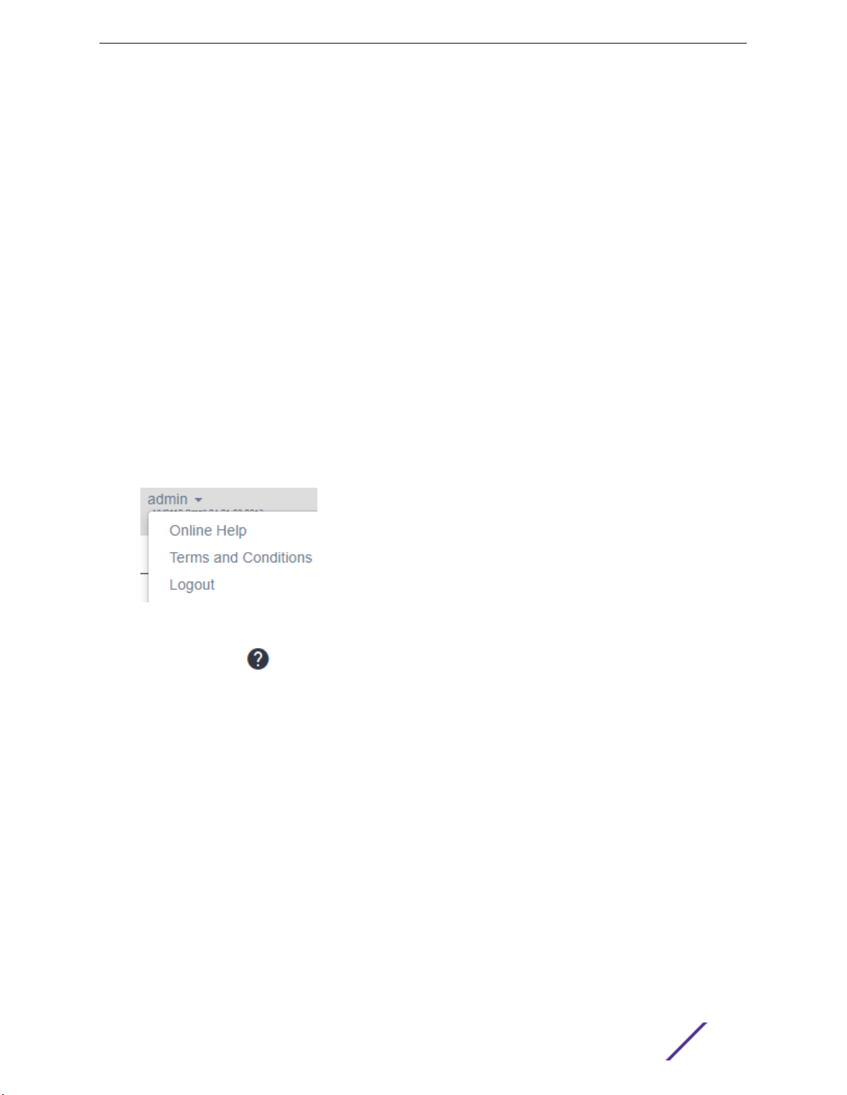
ExtremeCloud Appliance oers a context-sensitive Online Help system. Click the drop-down admin
menu on any page to access the topic-based Help System.
Figure 4: ExtremeCloud Appliance admin menu
Additionally, click on each dialog to display Help content for that dialog.
The Online Help file organization corresponds to the workbench structure of ExtremeCloud Appliance.
The Online Help file oers a Table of Contents, Search Facility, and Index so you can find the information
that you need.
Also on the admin menu, you will find the Terms and Conditions and Logout options.
Related Links
Overview Dashboard on page 22
Search Facility
Each list page in ExtremeCloud Appliance oers a search facility so you can easily find what you are
looking for based on specific criteria. Regular expression search, including wild cards is not supported.
ExtremeCloud Appliance User Guide for version 4.36.03 19

Welcome to ExtremeCloud Appliance
Configuring Column Display
Configure which columns display on a list screen. To configure the column display:
1
Select to display the list of columns.
2 Select a column to display. Or, clear the check mark to hide the column.
You can also export the data to a .csv file (Comma Separated Value). Select Export all Data to CSV or
Export Visible Data to CSV. A spreadsheet with data is created in your Downloads folder.
Understanding Date and Time
The dates and times that you see displayed in the user interface represent the local time zone of your
browser. This can be dierent from the time zone of the appliance where ExtremeCloud Appliance is
installed.
For example, if ExtremeCloud Appliance is installed on an appliance in EDT time zone, and your browser
is installed on a machine in PDT time zone, the time represented in the detail views and logs will be in
PDT, the time zone of the browser.
NEW!
In this scenario, if you register a client with ExtremeCloud Appliance at 8:30 EDT, the Event Logs and
Client Detail values show the time as 5:30.
Hierarchical Visibility for WiNG Appliances
ExtremeCloud Appliance oers unified visibility into Extreme Management Center for existing
ExtremeWireless WiNG installations. This option extends the reporting and visibility capabilities of
Extreme Management Center to ExtremeWireless WiNG accounts. This oers not only as an alternative
to NSight, but supports unified wireless, wired infrastructure and expands other Extreme Networks
software oerings, such as ExtremeAnalytics. If you are already leveraging NSight, this solution
continues to support that investment. ExtremeCloud Appliance will relay statistics that feed into NSight
to keep it's visibility value intact.
APs and appliances running ExtremeWireless WiNG version 5.9.1 or later are supported in this
deployment strategy. ExtremeWireless WiNG APs are adopted by the WiNG appliance, and their
configuration and statistics are fed through ExtremeCloud Appliance for presentation in NSight.
The ExtremeCloud Appliance Statistics Proxy function leverages the ExtremeWireless WiNG stats
connection that typically feeds NSight. The connection may already be in use if you are using the NSight
product on the ExtremeWireless WiNG deployment. To support compatibility with the installed base,
ExtremeCloud Appliance can relay the stats to feed the NSight (cluster).
You can opt to configure ExtremeCloud Appliance as an external NSight server for an ExtremeWireless
WiNG controller or as an additional proxy server between ExtremeWireless WiNG and NSight. The
NSight server displays stats from proxy APs along side other AP stats. The ExtremeCloud Appliance is
completely transparent to NSight.
A proxy AP is an AP that has been adopted by an ExtremeWireless WiNG controller. The AP statistics
and configuration are fed from the controller through ExtremeCloud Appliance for display in NSight.
Proxy APs and their associated components are all marked as Proxied in the ExtremeCloud Appliance:
ExtremeCloud Appliance User Guide for version 4.36.03 20

Welcome to ExtremeCloud Appliance
AP List — APs that are adopted by an ExtremeWireless WiNG controller are listed as Proxied on the
•
ExtremeCloud Appliance AP page.
Site List — RF domains associated with the proxy AP are listed as Proxied on the ExtremeCloud
•
Appliance Sites page. The Country designation for a site is derived from the AP RF domain. When
there are no APs assigned to an RF domain, the Country designation for the site is “Demo Country”.
Networks List — Networks associated with the proxy AP are listed as Proxied on the ExtremeCloud
•
Appliance Networks page, and a proxy network displays the network name, SSID, privacy/
encryption and VLAN of the ExtremeWireless WiNG network. The default role is “Enterprise User”
for a proxy network.
VLAN List — VLANs associated with the proxy AP are listed as Proxied on the ExtremeCloud
•
Appliance VLAN page. A proxy VLAN topology is always "Bridged at AP, tagged". If a network
references a VLAN that is configured in ExtremeCloud Appliance, that existing VLAN is used by the
proxy network.
Controller List — ExtremeWireless WiNG proxy controllers configured for NSight are listed in
•
ExtremeCloud Appliance under Monitor > Devices > Controllers. Proxied controllers can be
removed from the Controllers page. However, if the ExtremeWireless WiNG controller has
ExtremeCloud Appliance in its configuration, the ExtremeWireless WiNGcontroller reappears in the
list of controllers after each update. Proxy controllers cannot be edited.
All relevant information and statistics for a proxy AP displays in ExtremeCloud Appliance. However,
editing and troubleshooting are not available in ExtremeCloud Appliance for a proxy AP or its
associated: site, network, or VLAN.
Note
A proxy AP and its associated components can be removed from the ExtremeCloud
Appliance. However, as long as the AP is adopted by the ExtremeWireless WiNG controller,
the AP, site, network, and VLAN are re-created each time the controller sends an update to
ExtremeCloud Appliance.
APs that are adopted by a ExtremeWireless WiNG controller continue to provide data to
ExtremeWireless WiNG wizards and dashboards, as well as feed data to ExtremeCloud Appliance.
For information about the deployment strategy and configuration of the ExtremeCloud Appliance
statistics proxy functionality, see the ExtremeCloud Appliance Deployment Guide.
Related Links
NSight Configuration on page 202
Controllers List on page 52
ExtremeCloud Appliance User Guide for version 4.36.03 21
2 Dashboard
Overview Dashboard
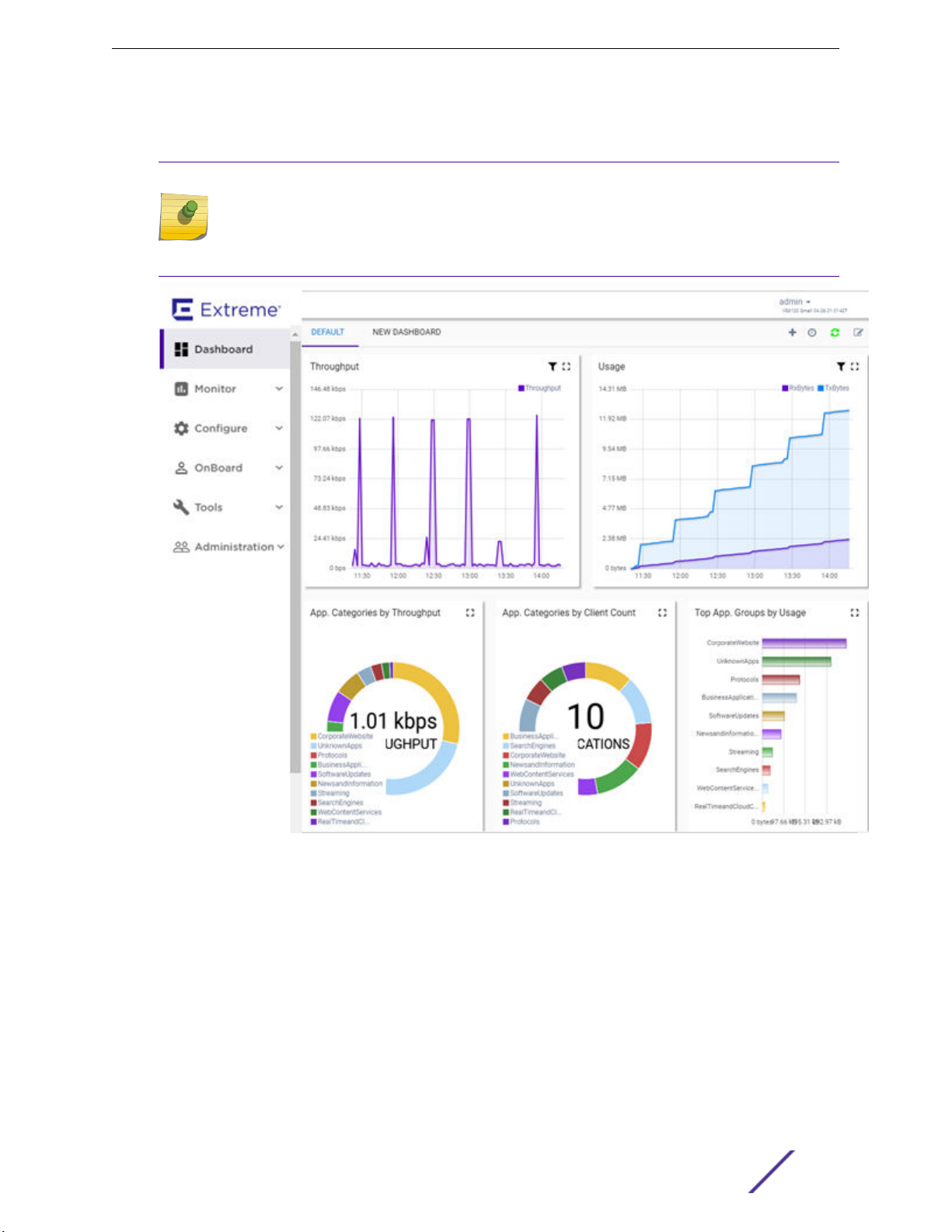
Overview Dashboard
Monitor your network activity and performance on the Overview dashboard. The Overview dashboard
displays widgets that can help you proactively monitor and troubleshoot your network. The dashboard
provides a graphical representation of information related to devices, clients, and network trac.
Depending on the report, the widget represents historical data or a combination of historical and the
latest data from shared memory.
Note
Historical data is persistent after system restarts and software upgrades, but not if the system
is restored to the factory defaults or from a backup.
ExtremeCloud Appliance is installed with a Default dashboard. You can customize the default
dashboard and add additional dashboards with custom layouts and a unique set of widgets. The
maximum number of supported dashboards is 10. The free-form dashboard can have a maximum of 10
widgets.
The Overview dashboard widgets are classified according to the type of data they access:
Network utilization metrics including top and bottom values for clients, APs, switches, and networks
•
Radio Frequency metrics
•
Switches with top and bottom throughput levels
•
Client distribution and client count for the top and bottom manufacturer, network, and operating
•
system
Captive Portal metrics that include details on guests associated with the network and dwell time for
•
each guest
Application Visibility metrics categorize applications and application groups by throughput, client
•
count, usage, and unique users
System metrics that indicate network health.
•
Troubleshooting that displays packet capture instances.
•
Combine widgets from any of the categories to create one or more unique dashboards.
Additionally:
Click to set the Duration value for the time period reported. Valid duration values are:
•
Last 3 hours
•
Last 3 days
•
Last 14 days
•
Click to refresh the data on demand.
•
Hover the mouse over a widget to display tool tip information.
•
ExtremeCloud Appliance User Guide for version 4.36.03 22
Dashboard
Filter data by radio band on each chart, individually. Click to show radio band filters on each chart. Then
select the 2.4GHz or 5GHz radio button to display data for that band.
Note
The datasets are sampled at dierent intervals. Therefore, it is possible that data from the 14-
day dataset will not include data from the 3-day dataset or from the 3-hour dataset. It is
possible that a new client will not appear in a dataset if the dataset has not been recently
updated.
Figure 5: Main Dashboard
Related Links
Adding a New Dashboard on page 23
Modifying a Dashboard on page 24
Understanding Date and Time on page 20
Availability Link Status on page 26
Adding a New Dashboard
Create additional dashboards to organize network data.
ExtremeCloud Appliance User Guide for version 4.36.03 23
Dashboard
To add a new dashboard:
1 From the default dashboard, click the plus sign.
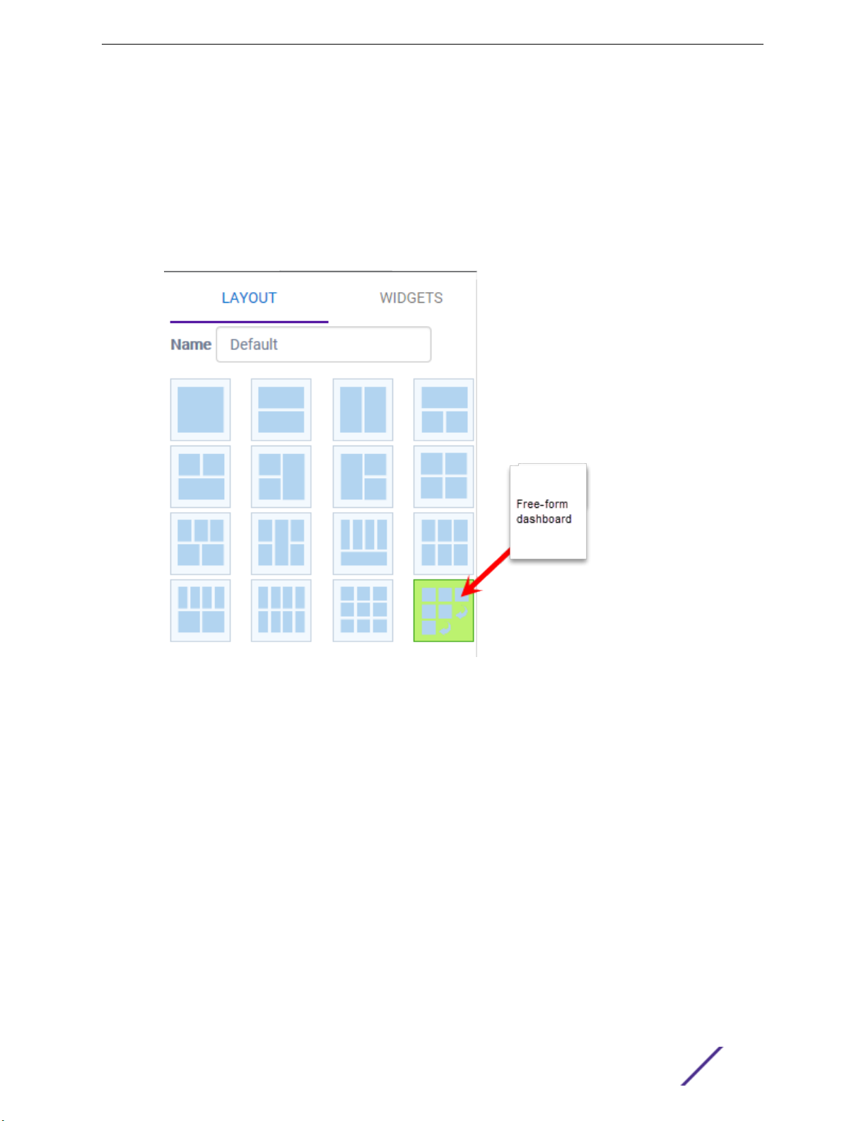
The Layout tab displays.
2 In the Name field, enter a name for the dashboard.
3 Select a layout option for the dashboard.
Each layout option has a set configuration. Choose the layout that matches the number of widgets
you want to display. The last widget option allows you to display up to 10 widgets.
Figure 6: Widget Layout Options
4 Select the Widgets tab.
The list of widgets by category is displayed.
5 Expand the list of widgets in each category.
6 Drag and drop a widget onto the dashboard, within the layout that you have selected.
7 Click Save.
Modifying a Dashboard
You can customize the default dashboard views to fit your network's analytic requirements, such as
monitoring the topology, component health, and device performance.
To modify a dashboard:
ExtremeCloud Appliance User Guide for version 4.36.03 24
Dashboard
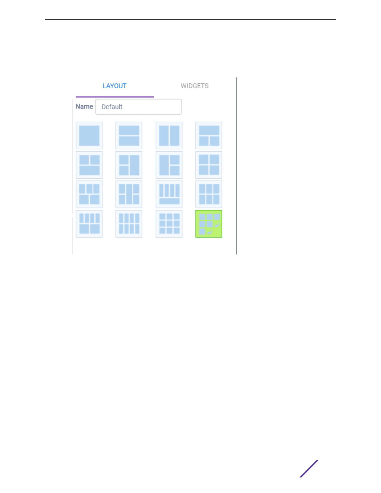
1 From the Overview Dashboard page or from the dashboard page of a specific entity, such as a
device, select Edit.
The Layout and Widgets tabs display on the far right.
Figure 7: Dashboard - Edit Mode
2 From the Layout tab, select a layout.
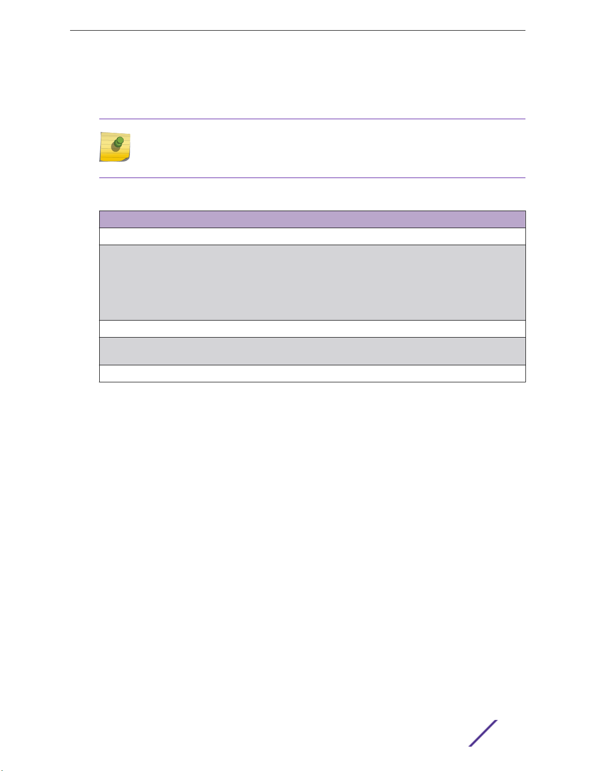
3 From the Widgets tab, expand the categories that you want to use. Select the widgets that you want
included in the layout. The following widget categories are available:
Utilization
RF Provides Radio Frequency metrics such as RF quality, RF health, channel utilization, and
Switch Tracks top and bottom switches by throughput.
Clients Tracks client distribution based on dierent parameters.
Application Visibility Provides application visibility metrics.
System System metrics indicate network health.
Provides utilization metrics such as client count, and various top 10 and bottom 10
counts.
various top 10 and bottom 10 metrics. This group also includes various Smart RF metrics.
4 Click Save.
ExtremeCloud Appliance User Guide for version 4.36.03 25
Availability Link Status
Once an Availability Pair is configured, the synchronization status between the paired appliances is
displayed on the Dashboard Network Health chart. Table 4 describes each possible link status.
Note
Both client and AP statistics remain available on both sides of an availability pair. However,
cross-appliance statistical data can be aected if a mobile user is roaming across multiple APs
when the availability pair connection between the appliances is down.
Table 4: Synchronization Status for an Availability Pair
Status Description
Unknown Link is down.
Synchronized All changes are pushed to the peer appliance.
Note: There may be a brief period when a change on the first appliance has not yet
been pushed to the second appliance. During this time, you could see "Changed" on
one appliance and "Synchronized" on the other appliance. This will be resolved as
soon as the change has successfully been pushed to the second appliance.
Dashboard
Synchronizing Changes are being pushed to the peer.
Changed Not synchronized. There are pending changes that have not been pushed to the peer
Failed Synchronization failed.
Related Links
Availability on page 195
appliance.
ExtremeCloud Appliance User Guide for version 4.36.03 26

3 Monitor
Sites List
Device List
Networks List
Clients
Policy
Sites List
Go to Monitor > Sites to view a list of sites configured in ExtremeCloud Appliance. Select a site to view
the site dashboard and related components.
Related Links
Sites Overview on page 10
Centralized Site on page 10
Distributed Site on page 11
Adding a Site on page 64
Site Dashboard on page 27
Modifying Site Configuration on page 65
Site Location on page 67
Configuring Column Display on page 20
Site Dashboard
The Site Dashboard oers report information on the following topics:
Site Utilization. Provides metrics on the amount of trac passing through the site.
•
RF Management. Provides metrics on radio frequency quality and channel utilization.
•
Switches. Provides metrics on switch throughput.
•
Clients. Provides metrics on client distribution by protocol and client count by manufacturer,
•
operating system, and network.
Captive Portal. Provides metrics on users who access the network through captive portal.
•
Application Visibility. Provides metrics on application groups related to throughput, client count, and
•
usage.
Location. (Positioning) Provides metrics identifying visitor trac by floor or area. (Supported on
•
AP39xx only.)
Related Links
Adding a New Dashboard on page 23
Modifying a Dashboard on page 24
ExtremeCloud Appliance User Guide for version 4.36.03 27
Network Snapshot: Sites
To view network details from the Sites screen:
1 Go to Monitor > Sites and select a site.
The Site Dashboard displays.
2 Select any of the tabs described in the following table.
Table 5: Tabs on the Sites Screen
Tab Description
Dashboard Site dashboard that displays network metrics for the site.
Networks Lists the network services associated with the site. Select a network to
display network details.
Access Points List of access points associated with the site. For more information,
see:
•
•
Monitor
AP Actions on page 106
Radio Settings Button on page 28
Switches List of switches associated with the site.
Clients List of clients associated with the site.
Troubleshooting Oers packet capture at the AP and remote console access to the AP.
Floor Plans Floor plans associated with the site.
Related Links
Site Dashboard on page 27
Network Service Settings on page 119
Access Points List on page 40
Switches on page 113
Clients on page 53
Opening Live SSH Console to a Selected AP on page 49
Packet Capture on page 45
Floor Plans on page 16
Radio Settings Button
The following radio settings are available for 5GHz and 2.4GHz radios.
ExtremeCloud Appliance User Guide for version 4.36.03 28
Monitor
Table 6: Radio Settings
Field Description
Set Tx Power
Channel Width Determines the channel width used by the channel on the selected
radio. Available options include:
20 MHz
•
40 MHz
•
80 MHz (supported on 5GHz only 802.11ac and 802.11ax)
•
160 MHz (supported on 5GHz only 802.11ax)
•
Automatic – Channel width is calculated automatically. This is the
•
default value.
Channel Select from the list of available channels.
Max Tx Power (dBm) Determines the maximum power level that can be used by the radio in
dBm. The values are governed by compliance requirements based on
the country, radio, and antenna selected, and will vary by AP.
Set Channel Width
Channel Width Set the default channel width for the selected radio.
20 MHz
•
40 MHz
•
80 MHz (supported on 5GHz only 802.11ac and 802.11ax)
•
160 MHz (supported on 5GHz only 802.11ax)
•
Automatic – Channel width is calculated automatically. This is the
•
default value.
Auto Channel Select ACS optimizes channel arrangement based on the current situation in
the field if it is triggered on all APs in a deployment. ACS only relies on
the information observed at the time it is triggered. Once an AP has
selected a channel, it remains operating on that channel until the user
changes the channel or triggers ACS.
Floor Plan View
Once the floor plan is configured, view the floor plan from Monitor > Sites. From the floor plan View.
you can view and filter information related to the placed devices.
Go to Monitor > Sites. Select a site and click the Floor Plans tab.
View the following map information across the top of the screen:
•
Map area, network coverage, environment, and scale.
•
Number of ceiling mounted APs.
•
Number of wall mounted APs.
•
Number of devices in each status.
•
Control which device badges appear on the map based on the selected device group or statistical
•
thresholds.
View status, details, and statistics for each device.
•
ExtremeCloud Appliance User Guide for version 4.36.03 29
View clients associated with a selected device.
•
View map zones for AP location.
•
Related Links
Viewing a Floor Plan on page 30
Floor Plans on page 16
Configuring a Floor Plan on page 96
Viewing a Floor Plan
Once the floor plan is configured, view it from a selected site's dashboard. The floor plan represents
placed devices and associated badges that show configuration and performance data for the device.
From the Floor Plans view, you can toggle between floors, filter data, and further fine-tune the map
display.
To access Floor Plans view, go to Monitor > Sites, select a sight and click Floor Plans.
If one or more floor plans exist, available floor plans display in the right-side pane.
Monitor
Here are a few things you can do with a floor plan:
To search for devices:
•
Click the search icon .
•
Click on the search field and select device from the drop-down list.
•
To zoom in and out, do one of the following:
•
Click to zoom in.
•
Click
•
•
•
Check device Status:
•
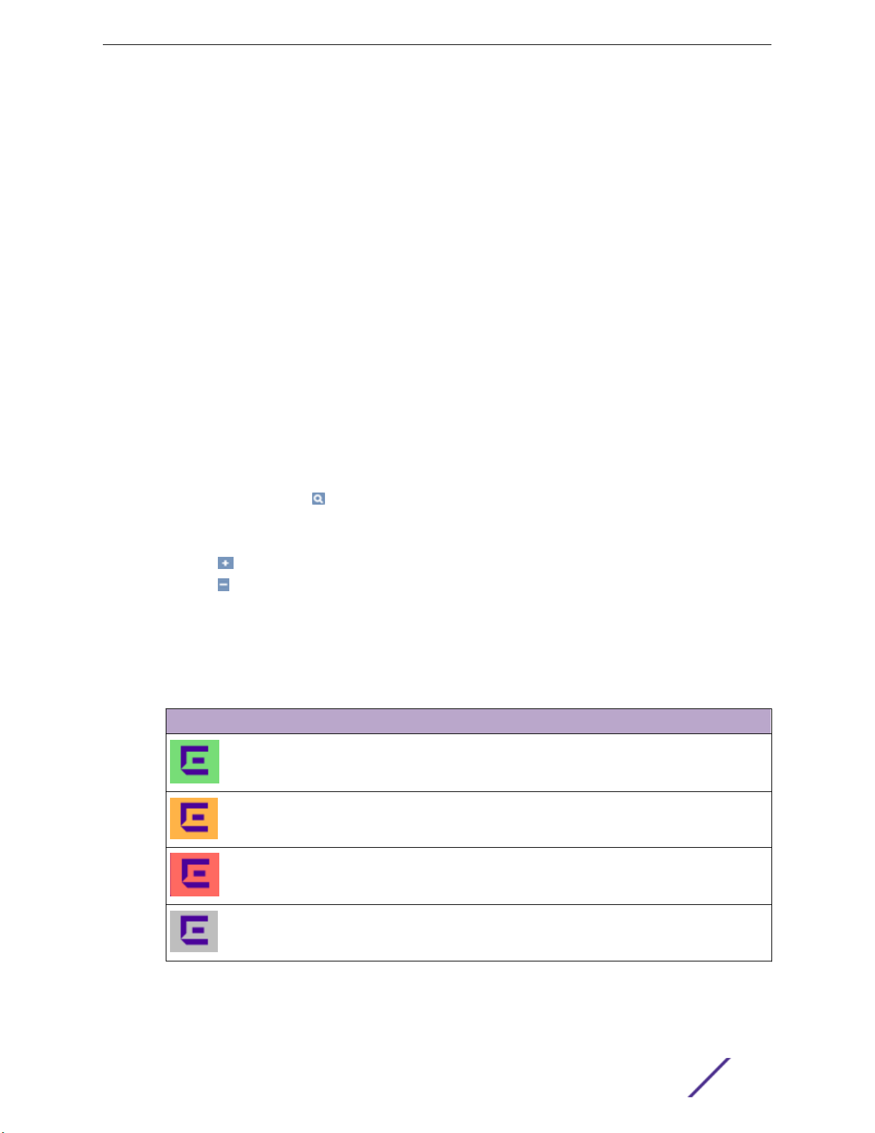
Table 7: Device Status from the Floor Plans View
Status Description
to zoom out.
Double-click on the map to zoom in. Use the mouse scroll wheel to zoom out.
Click the map and use the mouse scroll wheel to zoom in and out.
AP is in-service, operating.
In-service, trouble.
Critical. Indicates that ExtremeCloud Appliance cannot
communicate with the AP.
Unknown. AP is unknown to the displayed floor plan based on floor
plan filter settings. Typically occurs when the device group for the
AP is not selected.
ExtremeCloud Appliance User Guide for version 4.36.03 30
 Loading...