

Extreme Networks ERS 4950GTS, ERS 4926GTS, ERS 4950GTS-PWR+, ERS 4926GTS-PWR+ operation manual

Installing Ethernet Routing Switch 4900
Series
Release 7.6
9035402
May 2018

©
2018, Extreme Networks, Inc.
All Rights Reserved.
Notice
While reasonable efforts have been made to ensure that the
information in this document is complete and accurate at the time of
printing, Extreme Networks, Inc. assumes no liability for any errors.
Extreme Networks, Inc. reserves the right to make changes and
corrections to the information in this document without the obligation
to notify any person or organization of such changes.
Documentation disclaimer
“Documentation” means information published in varying mediums
which may include product information, operating instructions and
performance specifications that are generally made available to users
of products. Documentation does not include marketing materials.
Extreme Networks shall not be responsible for any modifications,
additions, or deletions to the original published version of
Documentation unless such modifications, additions, or deletions
were performed by or on the express behalf of Extreme Networks.
End User agrees to indemnify and hold harmless Extreme Networks,
Extreme Networks’ agents, servants and employees against all
claims, lawsuits, demands and judgments arising out of, or in
connection with, subsequent modifications, additions or deletions to
this documentation, to the extent made by End User.
Link disclaimer
Extreme Networks is not responsible for the contents or reliability of
any linked websites referenced within this site or Documentation
provided by Extreme Networks. Extreme Networks is not responsible
for the accuracy of any information, statement or content provided on
these sites and does not necessarily endorse the products, services,
or information described or offered within them. Extreme Networks
does not guarantee that these links will work all the time and has no
control over the availability of the linked pages.
Warranty
Extreme Networks provides a limited warranty on Extreme Networks
hardware and software. Refer to your sales agreement to establish
the terms of the limited warranty. In addition, Extreme Networks’
standard warranty language, as well as information regarding support
for this product while under warranty is available to Extreme
Networks customers and other parties through the Extreme Networks
Support website:
http://www.extremenetworks.com/support under the
link ““Policies” or such successor site as designated by Extreme
Networks. Please note that if You acquired the product(s) from an
authorized Extreme Networks Channel Partner outside of the United
States and Canada, the warranty is provided to You by said Extreme
Networks Channel Partner and not by Extreme Networks.
“Hosted Service” means an Extreme Networks hosted service
subscription that You acquire from either Extreme Networks or an
authorized Extreme Networks Channel Partner (as applicable) and
which is described further in Hosted SAS or other service description
documentation regarding the applicable hosted service. If You
purchase a Hosted Service subscription, the foregoing limited
warranty may not apply but You may be entitled to support services
in connection with the Hosted Service as described further in your
service description documents for the applicable Hosted Service.
Contact Extreme Networks or Extreme Networks Channel Partner (as
applicable) for more information.
Hosted Service
THE FOLLOWING APPLIES ONLY IF YOU PURCHASE AN
EXTREME NETWORKS HOSTED SERVICE SUBSCRIPTION
FROM EXTREME NETWORKS OR AN EXTREME NETWORKS
CHANNEL PARTNER (AS APPLICABLE), THE TERMS OF USE
FOR HOSTED SERVICES ARE AVAILABLE ON THE EXTREME
NETWORKS WEBSITE,
https://extremeportal.force.com OR SUCH
SUCCESSOR SITE AS DESIGNATED BY EXTREME NETWORKS,
AND ARE APPLICABLE TO ANYONE WHO ACCESSES OR USES
THE HOSTED SERVICE. BY ACCESSING OR USING THE
HOSTED SERVICE, OR AUTHORIZING OTHERS TO DO SO, YOU,
ON BEHALF OF YOURSELF AND THE ENTITY FOR WHOM YOU
ARE DOING SO (HEREINAFTER REFERRED TO
INTERCHANGEABLY AS “YOU” AND “END USER”), AGREE TO
THE TERMS OF USE. IF YOU ARE ACCEPTING THE TERMS OF
USE ON BEHALF A COMPANY OR OTHER LEGAL ENTITY, YOU
REPRESENT THAT YOU HAVE THE AUTHORITY TO BIND SUCH
ENTITY TO THESE TERMS OF USE. IF YOU DO NOT HAVE SUCH
AUTHORITY, OR IF YOU DO NOT WISH TO ACCEPT THESE
TERMS OF USE, YOU MUST NOT ACCESS OR USE THE
HOSTED SERVICE OR AUTHORIZE ANYONE TO ACCESS OR
USE THE HOSTED SERVICE.
Licenses
THE SOFTWARE LICENSE TERMS AVAILABLE ON THE
EXTREME NETWORKS WEBSITE,
https://extremeportal.force.com
OR SUCH SUCCESSOR SITE AS DESIGNATED BY EXTREME
NETWORKS, ARE APPLICABLE TO ANYONE WHO
DOWNLOADS, USES AND/OR INSTALLS EXTREME NETWORKS
SOFTWARE, PURCHASED FROM EXTREME NETWORKS, INC.,
ANY EXTREME NETWORKS AFFILIATE, OR AN EXTREME
NETWORKS CHANNEL PARTNER (AS APPLICABLE) UNDER A
COMMERCIAL AGREEMENT WITH EXTREME NETWORKS OR
AN EXTREME NETWORKS CHANNEL PARTNER. UNLESS
OTHERWISE AGREED TO BY EXTREME NETWORKS IN
WRITING, EXTREME NETWORKS DOES NOT EXTEND THIS
LICENSE IF THE SOFTWARE WAS OBTAINED FROM ANYONE
OTHER THAN EXTREME NETWORKS, AN EXTREME
NETWORKS AFFILIATE OR AN EXTREME NETWORKS CHANNEL
PARTNER; EXTREME NETWORKS RESERVES THE RIGHT TO
TAKE LEGAL ACTION AGAINST YOU AND ANYONE ELSE USING
OR SELLING THE SOFTWARE WITHOUT A LICENSE. BY
INSTALLING, DOWNLOADING OR USING THE SOFTWARE, OR
AUTHORIZING OTHERS TO DO SO, YOU, ON BEHALF OF
YOURSELF AND THE ENTITY FOR WHOM YOU ARE
INSTALLING, DOWNLOADING OR USING THE SOFTWARE
(HEREINAFTER REFERRED TO INTERCHANGEABLY AS “YOU”
AND “END USER”), AGREE TO THESE TERMS AND CONDITIONS
AND CREATE A BINDING CONTRACT BETWEEN YOU AND
EXTREME NETWORKS, INC. OR THE APPLICABLE EXTREME
NETWORKS AFFILIATE (“EXTREME NETWORKS”).
Extreme Networks grants You a license within the scope of the
license types described below. Where the order documentation does
not expressly identify a license type, the applicable license will be a
Designated System License as set forth below in the Designated
System(s) License (DS) section as applicable. The applicable
number of licenses and units of capacity for which the license is
granted will be one (1), unless a different number of licenses or units
of capacity is specified in the documentation or other materials
available to You. “Software” means computer programs in object
code, provided by Extreme Networks or an Extreme Networks
Channel Partner, whether as stand-alone products, pre-installed on
hardware products, and any upgrades, updates, patches, bug fixes,
or modified versions thereto. “Designated Processor” means a single
stand-alone computing device. “Server” means a set of Designated
Processors that hosts (physically or virtually) a software application
to be accessed by multiple users. “Instance” means a single copy of
the Software executing at a particular time: (i) on one physical
machine; or (ii) on one deployed software virtual machine (“VM”) or
similar deployment.
License type(s)
Designated System(s) License (DS). End User may install and use
each copy or an Instance of the Software only: 1) on a number of
Designated Processors up to the number indicated in the order; or 2)
up to the number of Instances of the Software as indicated in the
order, Documentation, or as authorized by Extreme Networks in
writing. Extreme Networks may require the Designated Processor(s)
to be identified in the order by type, serial number, feature key,
Instance, location or other specific designation, or to be provided by
End User to Extreme Networks through electronic means established
by Extreme Networks specifically for this purpose.
Copyright
Except where expressly stated otherwise, no use should be made of
materials on this site, the Documentation, Software, Hosted Service,
or hardware provided by Extreme Networks. All content on this site,
the documentation, Hosted Service, and the product provided by
Extreme Networks including the selection, arrangement and design
of the content is owned either by Extreme Networks or its licensors
and is protected by copyright and other intellectual property laws
including the sui generis rights relating to the protection of databases.
You may not modify, copy, reproduce, republish, upload, post,
transmit or distribute in any way any content, in whole or in part,

including any code and software unless expressly authorized by
Extreme Networks. Unauthorized reproduction, transmission,
dissemination, storage, and or use without the express written
consent of Extreme Networks can be a criminal, as well as a civil
offense under the applicable law.
Virtualization
The following applies if the product is deployed on a virtual machine.
Each product has its own ordering code and license types. Note,
unless otherwise stated, that each Instance of a product must be
separately licensed and ordered. For example, if the end user
customer or Extreme Networks Channel Partner would like to install
two Instances of the same type of products, then two products of that
type must be ordered.
Third Party Components
“Third Party Components” mean certain software programs or
portions thereof included in the Software or Hosted Service may
contain software (including open source software) distributed under
third party agreements (“Third Party Components”), which contain
terms regarding the rights to use certain portions of the Software
(“Third Party Terms”). As required, information regarding distributed
Linux OS source code (for those products that have distributed Linux
OS source code) and identifying the copyright holders of the Third
Party Components and the Third Party Terms that apply is available
in the products, Documentation or on Extreme Networks’ website
at:http://www.extremenetworks.com/support/policies/software-
licensing or such successor site as designated by Extreme Networks.
The open source software license terms provided as Third Party
Terms are consistent with the license rights granted in these Software
License Terms, and may contain additional rights benefiting You,
such as modification and distribution of the open source software.
The Third Party Terms shall take precedence over these Software
License Terms, solely with respect to the applicable Third Party
Components to the extent that these Software License Terms impose
greater restrictions on You than the applicable Third Party Terms.
The following applies only if the H.264 (AVC) codec is distributed with
the product. THIS PRODUCT IS LICENSED UNDER THE AVC
PATENT PORTFOLIO LICENSE FOR THE PERSONAL USE OF A
CONSUMER OR OTHER USES IN WHICH IT DOES NOT RECEIVE
REMUNERATION TO (i) ENCODE VIDEO IN COMPLIANCE WITH
THE AVC STANDARD (“AVC VIDEO”) AND/OR (ii) DECODE AVC
VIDEO THAT WAS ENCODED BY A CONSUMER ENGAGED IN A
PERSONAL ACTIVITY AND/OR WAS OBTAINED FROM A VIDEO
PROVIDER LICENSED TO PROVIDE AVC VIDEO. NO LICENSE IS
GRANTED OR SHALL BE IMPLIED FOR ANY OTHER USE.
ADDITIONAL INFORMATION MAY BE OBTAINED FROM MPEG LA,
L.L.C. SEE
Service Provider
THE FOLLOWING APPLIES TO EXTREME NETWORKS CHANNEL
PARTNER’S HOSTING OF EXTREME NETWORKS PRODUCTS
OR SERVICES. THE PRODUCT OR HOSTED SERVICE MAY USE
THIRD PARTY COMPONENTS SUBJECT TO THIRD PARTY
TERMS AND REQUIRE A SERVICE PROVIDER TO BE
INDEPENDENTLY LICENSED DIRECTLY FROM THE THIRD
PARTY SUPPLIER. AN EXTREME NETWORKS CHANNEL
PARTNER’S HOSTING OF EXTREME NETWORKS PRODUCTS
MUST BE AUTHORIZED IN WRITING BY EXTREME NETWORKS
AND IF THOSE HOSTED PRODUCTS USE OR EMBED CERTAIN
THIRD PARTY SOFTWARE, INCLUDING BUT NOT LIMITED TO
MICROSOFT SOFTWARE OR CODECS, THE EXTREME
NETWORKS CHANNEL PARTNER IS REQUIRED TO
INDEPENDENTLY OBTAIN ANY APPLICABLE LICENSE
AGREEMENTS, AT THE EXTREME NETWORKS CHANNEL
PARTNER’S EXPENSE, DIRECTLY FROM THE APPLICABLE
THIRD PARTY SUPPLIER.
WITH RESPECT TO CODECS, IF THE EXTREME NETWORKS
CHANNEL PARTNER IS HOSTING ANY PRODUCTS THAT USE
OR EMBED THE G.729 CODEC, H.264 CODEC, OR H.265
CODEC, THE EXTREME NETWORKS CHANNEL PARTNER
ACKNOWLEDGES AND AGREES THE EXTREME NETWORKS
CHANNEL PARTNER IS RESPONSIBLE FOR ANY AND ALL
RELATED FEES AND/OR ROYALTIES. THE G.729 CODEC IS
LICENSED BY SIPRO LAB TELECOM INC. SEE
WWW.SIPRO.COM/CONTACT.HTML. THE H.264 (AVC) CODEC IS
LICENSED UNDER THE AVC PATENT PORTFOLIO LICENSE FOR
HTTP://WWW.MPEGLA.COM.
THE PERSONAL USE OF A CONSUMER OR OTHER USES IN
WHICH IT DOES NOT RECEIVE REMUNERATION TO: (I) ENCODE
VIDEO IN COMPLIANCE WITH THE AVC STANDARD (“AVC
VIDEO”) AND/OR (II) DECODE AVC VIDEO THAT WAS ENCODED
BY A CONSUMER ENGAGED IN A PERSONAL ACTIVITY AND/OR
WAS OBTAINED FROM A VIDEO PROVIDER LICENSED TO
PROVIDE AVC VIDEO. NO LICENSE IS GRANTED OR SHALL BE
IMPLIED FOR ANY OTHER USE. ADDITIONAL INFORMATION
FOR H.264 (AVC) AND H.265 (HEVC) CODECS MAY BE
OBTAINED FROM MPEG LA, L.L.C. SEE
WWW.MPEGLA.COM.
Compliance with Laws
You acknowledge and agree that it is Your responsibility for
complying with any applicable laws and regulations, including, but not
limited to laws and regulations related to call recording, data privacy,
intellectual property, trade secret, fraud, and music performance
rights, in the country or territory where the Extreme Networks product
is used.
Preventing Toll Fraud
“Toll Fraud” is the unauthorized use of your telecommunications
system by an unauthorized party (for example, a person who is not a
corporate employee, agent, subcontractor, or is not working on your
company's behalf). Be aware that there can be a risk of Toll Fraud
associated with your system and that, if Toll Fraud occurs, it can
result in substantial additional charges for your telecommunications
services.
Security Vulnerabilities
Information about Extreme Networks’ security support policies can be
found in the Global Technical Assistance Center Knowledgebase at
https://gtacknowledge.extremenetworks.com/.
Downloading Documentation
For the most current versions of Documentation, see the Extreme
Networks Support website:
documentation.extremenetworks.com, or such successor site as
designated by Extreme Networks.
Contact Extreme Networks Support
See the Extreme Networks Support website:
www.extremenetworks.com/support for product or Hosted Service
notices and articles, or to report a problem with your Extreme
Networks product or Hosted Service. For a list of support telephone
numbers and contact addresses, go to the Extreme Networks
Support website:
(or such successor site as designated by Extreme Networks), scroll
to the bottom of the page, and select Contact Extreme Networks
Support.
Trademarks
The trademarks, logos and service marks (“Marks”) displayed in this
site, the Documentation, Hosted Service(s), and product(s) provided
by Extreme Networks are the registered or unregistered Marks of
Extreme Networks, Inc., its affiliates, its licensors, its suppliers, or
other third parties. Users are not permitted to use such Marks without
prior written consent from Extreme Networks or such third party
which may own the Mark. Nothing contained in this site, the
Documentation, Hosted Service(s) and product(s) should be
construed as granting, by implication, estoppel, or otherwise, any
license or right in and to the Marks without the express written
permission of Extreme Networks or the applicable third party.
Extreme Networks is a registered trademark of Extreme Networks,
Inc.
All non-Extreme Networks trademarks are the property of their
respective owners. Linux® is the registered trademark of Linus
Torvalds in the U.S. and other countries.
For additional information on Extreme Networks trademarks, please
http://www.extremenetworks.com/company/legal/
see:
http://www.extremenetworks.com/support/contact/
http://
HTTP://
http://

Contents
Chapter 1: Preface.................................................................................................................... 6
Purpose.................................................................................................................................. 6
Training.................................................................................................................................. 6
Providing Feedback to Us........................................................................................................ 6
Getting Help............................................................................................................................ 7
Extreme Networks Documentation............................................................................................ 7
Subscribing to Service Notifications.......................................................................................... 8
Chapter 2: New in this document............................................................................................ 9
Chapter 3: Preinstallation checklist...................................................................................... 10
Chapter 4: Installation preparation....................................................................................... 12
Ethernet Routing Switch 4900 Series models.......................................................................... 12
Common hardware features............................................................................................. 13
Universal Serial Bus ports................................................................................................ 14
Electrostatic discharge prevention.......................................................................................... 15
Technical specifications......................................................................................................... 16
Power specifications........................................................................................................ 17
MTBF values................................................................................................................... 18
Power Supply Cords........................................................................................................ 19
Verifying the package contents............................................................................................... 21
Optional rack-mounting equipment.................................................................................... 22
Power Supply Unit specifications...................................................................................... 23
Connecting switch to AC power.............................................................................................. 23
Chapter 5: Switch installation................................................................................................ 24
Installing the switch in an equipment rack................................................................................ 24
Installing optional four-post rack-mount brackets...................................................................... 28
Installing the secondary power supply..................................................................................... 32
Connecting a transceiver to the switch or switch stack.............................................................. 33
Installing SFP transceivers............................................................................................... 33
Removing of SFP transceivers......................................................................................... 34
Supported optical devices ............................................................................................... 35
Cable requirements............................................................................................................... 37
Console port adapters ..................................................................................................... 37
Stacking............................................................................................................................... 38
Connecting switches in a stack......................................................................................... 41
Stack configurations........................................................................................................ 42
Replacing or adding a stack unit....................................................................................... 45
Removing a stack unit..................................................................................................... 45
Checking Light Emitting Diode on the switch............................................................................ 45
Switch LED state indicators.............................................................................................. 46
May 2018 Installing Ethernet Routing Switch 4900 Series 4

Contents
Port LED state indicators................................................................................................. 47
Chapter 6: Installation reference........................................................................................... 49
Console port pin assignments................................................................................................ 49
RJ-45 connector pin assignments for PoE switches................................................................. 49
Chapter 7: Translations of safety messages........................................................................ 51
Safety messages................................................................................................................... 51
May 2018 Installing Ethernet Routing Switch 4900 Series 5

Chapter 1: Preface
Purpose
This document provides the information and procedures required to install the hardware, software,
cabling, and power for the Extreme Networks Ethernet Routing Switch 4900 Series.
Unless otherwise indicated, this information applies to:
• ERS 4950GTS
• ERS 4926GTS
• ERS 4950GTS-PWR+
• ERS 4926GTS-PWR+
Training
Ongoing product training is available. For more information or to register, you can access the Web
site at www.extremenetworks.com/education/.
Providing Feedback to Us
We are always striving to improve our documentation and help you work better, so we want to hear
from you! We welcome all feedback but especially want to know about:
• Content errors or confusing or conflicting information.
• Ideas for improvements to our documentation so you can find the information you need faster.
• Broken links or usability issues.
If you would like to provide feedback to the Extreme Networks Information Development team about
this document, please contact us using our short
directly at internalinfodev@extremenetworks.com
online feedback form. You can also email us
May 2018 Installing Ethernet Routing Switch 4900 Series 6

Getting Help
If you require assistance, contact Extreme Networks using one of the following methods:
• GTAC (Global Technical Assistance Center) for Immediate Support
- Phone: 1-800-998-2408 (toll-free in U.S. and Canada) or +1 408-579-2826. For the support
phone number in your country, visit: www.extremenetworks.com/support/contact
Getting Help
- Email:
or model number in the subject line.
GTAC Knowledge – Get on-demand and tested resolutions from the GTAC Knowledgebase, or
•
create a help case if you need more guidance.
• The Hub – A forum for Extreme customers to connect with one another, get questions
answered, share ideas and feedback, and get problems solved. This community is monitored
by Extreme Networks employees, but is not intended to replace specific guidance from GTAC.
Support Portal – Manage cases, downloads, service contracts, product licensing, and training
•
and certifications.
Before contacting Extreme Networks for technical support, have the following information ready:
• Your Extreme Networks service contract number and/or serial numbers for all involved Extreme
Networks products
• A description of the failure
• A description of any action(s) already taken to resolve the problem
• A description of your network environment (such as layout, cable type, other relevant
environmental information)
• Network load at the time of trouble (if known)
• The device history (for example, if you have returned the device before, or if this is a recurring
problem)
support@extremenetworks.com. To expedite your message, enter the product name
• Any related RMA (Return Material Authorization) numbers
Extreme Networks Documentation
To find Extreme Networks product guides, visit our documentation pages at:
Current Product Documentation www.extremenetworks.com/documentation/
Archived Documentation (for previous
versions and legacy products)
Release Notes www.extremenetworks.com/support/release-notes
Open Source Declarations
Some software files have been licensed under certain open source licenses. More information is
available at:
May 2018 Installing Ethernet Routing Switch 4900 Series 7
www.extremenetworks.com/support/policies/software-licensing.
www.extremenetworks.com/support/documentationarchives/

Preface
Subscribing to Service Notifications
Subscribe to receive an email notification for product and software release announcements,
Vulnerability Notices, and Service Notifications.
About this task
You can modify your product selections at any time.
Procedure
1. In an Internet browser, go to http://www.extremenetworks.com/support/service-notification-
form/ .
2. Type your first and last name.
3. Type the name of your company.
4. Type your email address.
5. Type your job title.
6. Select the industry in which your company operates.
7. Confirm your geographic information is correct.
8. Select the products for which you would like to receive notifications.
9. Click Submit.
May 2018 Installing Ethernet Routing Switch 4900 Series 8

Chapter 2: New in this document
There are no feature changes in this release.
May 2018 Installing Ethernet Routing Switch 4900 Series 9
Chapter 3: Preinstallation checklist
Before you install the Ethernet Routing Switch 4900 Series, make sure that you complete the tasks
in the preinstallation checklist.
No. Task Description
1. Review the technical specification for the
switch. Make sure that the area where
you install the switch and where it will
operate meet the requirements.
2. Verify the power supply unit (PSU)
specifications. Optionally order a
redundant PSU to provide redundancy
and load sharing.
3. Make sure that you have the following
tools and cables:
• Phillips #2 screwdriver RJ-45 console
port cable
• ESD cable
4. Unpack the equipment. Observe ESD precautions when you
5. Verify the contents of the shipped
package.
6. Make sure that the power cord has the
correct country-specific termination.
7. Prepare the rack. Ensure that there is enough rack space
For the physical, electrical, and
environmental specifications, see
Technical specifications on page 16.
See AC power specifications on
page 17.
See Cable requirements on page 37.
unpack the equipment. See Electrostatic
discharge prevention on page 15.
See Verifying package contents on
page 21 for a description of the
components that are provided with the
switch. If any components are missing,
contact Extreme Networks support at
http://www.extremenetworks.com/
support.
See Power cord type and order codes on
page 19.
of 1.75 inches (4.45 centimeters).
Ensure that the rack is bolted to the floor
and braced if necessary.
Table continues…
May 2018 Installing Ethernet Routing Switch 4900 Series 10

No. Task Description
Ensure that the rack is grounded to the
same grounding electrode used by the
power service in the area. The ground
path must be permanent and must not
exceed 1 Ohm of resistance from the
rack to the grounding electrode.
See Installing the switch in an equipment
rack on page 24.
May 2018 Installing Ethernet Routing Switch 4900 Series 11

Chapter 4: Installation preparation
Ethernet Routing Switch 4900 Series models
This section provides information about the switches in Ethernet Routing Switch 4900 Series.
Ethernet Routing Switch 4900 Series models
The following table lists the different Ethernet Routing Switch 4900 Series models and the key
features for each switch.
Switch Model Key features Part Number
Ethernet Routing
Switch 4926GTS
• 24 ports, 10/100/1000 Base-T Ethernet
with two ports of SFP+ (10 Gbps)
interfaces
• Stackable Ethernet switch
• Non-PoE
AL4900A01-E6 (no power cord)
Ethernet Routing
Switch 4926GTSPWR+
Ethernet Routing
Switch 4950GTS
• Supports two modular 250 W Power
Supply Units (PSU), where one PSU is
required for operation and the optional
second is redundant
24 ports 10/100/1000BaseT
Stackable Ethernet switch
PoE
1 rack unit high
Uses modular power supply units and
has two field-serviceable power supply
receptacles, which support 250 W AC
power supply modules
48 ports 10/100/1000BaseT
Stackable Ethernet switch
Non-PoE
1 rack unit high
Uses modular power supply units and
has two field-serviceable power supply
AL4900A02-E6 (no power cord)
AL4900A03-E61 (no power cord)
Table continues…
May 2018 Installing Ethernet Routing Switch 4900 Series 12
Ethernet Routing Switch 4900 Series models
Switch Model Key features Part Number
receptacles, which support 1025 W AC
power supply modules
Ethernet Routing
Switch 4950GTSPWR+
Power cords must be ordered separately.
Depending on the switch model, a 250 W or 1025 W PSU and .5 m stacking cable is provided for all
switches.
48 ports 10/100/1000BaseT
Stackable Ethernet switch
PoE
1 rack unit high
Uses modular power supply units and
has two field-serviceable power supply
receptacles, which support 1025 W AC
power supply modules
AL4900A04-E6 (no power cord)
Common hardware features
The following hardware features are part of all switches in ERS 4900 Series:
• Standard ERS 19 inch rack mount hole pattern allowing horizontal or vertical, flush or offset,
front or rear mount options
• Front panel:
- one serial console connection
- one USB 2.1 Type A port
- status LED display panel
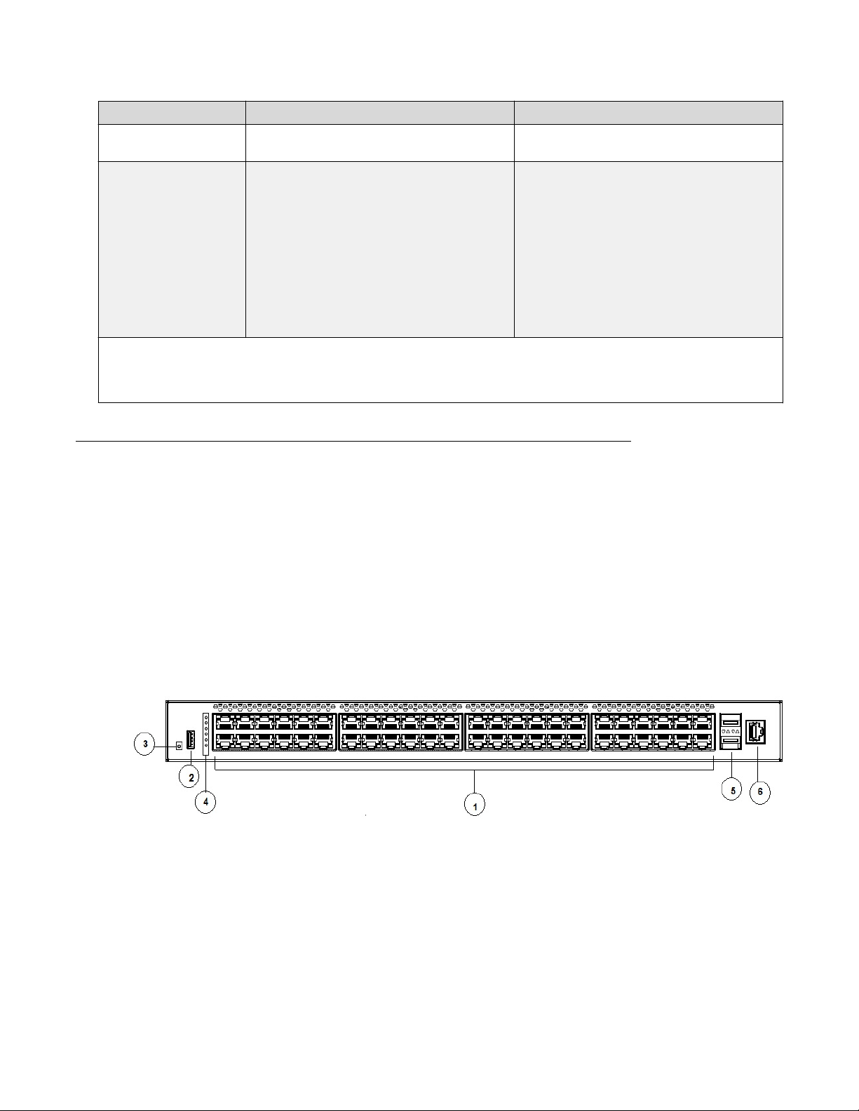
The following figure illustrates ERS 4900 Series front panel.
1. 10/100/1000 Ports (LEDs above the ports)
2. USB Type-A port
3. Reset push button
4. Status LEDs
5. SFP+ ports
6. Serial console port
Figure 1: Front panel
May 2018 Installing Ethernet Routing Switch 4900 Series 13
Installation preparation
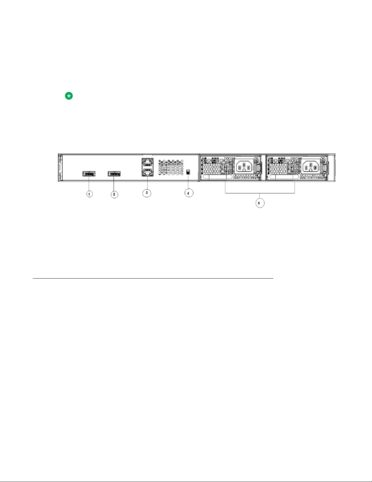
• Rear panel:
- two stack connectors
- one Base Select switch
- ports
Note:
The port labeled AUX is disabled.
- power supply units
- one Kensington Lock slot located on the left side, near the back end of the chassis
The following figure illustrates ERS 4900 Series rear panel.
1. Stack up connector
2. Stack down connector
3. Ports
4. Base Select Switch
5. Power Supply Units
Figure 2: Rear panel
Universal Serial Bus ports
The switches feature a Universal Serial Bus (USB) port on the front panel. Switch administrators can
use the USB port to perform tasks, previously performed through Trivial File Transfer Protocol
(TFTP), with a USB Mass Storage Device (for example, a flash drive or thumb drive):
• download software
• generate and download the ASCII configuration file
• generate and download the binary configuration file
The storage capacity of the USB device in use limits file and system operations.
Support is available only for USB drives that comply with the Mass Storage subsection of the USB
1.1 and USB 2.0 specification. Support does not extend to third-party devices that do not comply
with these standards. Off-the-shelf drives that do not comply with these standards cannot operate
with the switch. Only FAT or FAT32 file systems are currently supported; USB drives with NTFS file
systems are not supported. Consult the documentation provided with the USB drive to ensure
compliance with these standards.
May 2018 Installing Ethernet Routing Switch 4900 Series 14
Electrostatic discharge prevention
Electrostatic discharge prevention
This module provides information and procedures for the prevention of electrostatic discharge
during the installation process.
Electrostatic discharge (ESD) is a discharge of stored static electricity that can damage equipment
and impair electrical circuitry. These electrostatic voltages can result from friction, including, but not
exclusive to, pulling cabling through conduits, walking across carpeted areas, and building up of
static charge in clothing. ESD damage occurs when electronic components are improperly handled
and can result in complete or intermittent failures. While networking equipment is commonly
designed and tested to withstand common mode ESD events, voltage sometimes can be
discharged to some connector pins but not others, or to some pins before others, which has the
potential to damage the networking equipment.
To protect the switch against ESD damage, take the following preventive measures before
connecting any data cables to the device:
• Always use antistatic wrist straps. Make sure the strap is adjusted to provide good skin contact.
• Ensure that work surfaces and equipment racks are properly grounded for protection against
electrostatic discharge. The common point must be connected to the building ground wire. In a
properly wired building, the nearest reliable ground is typically at the electrical outlet.
• Avoid contact between equipment and clothing. The wrist or ankle strap only protects the
equipment from ESD voltages on the body; ESD voltages on clothing can still cause damage.
• Avoid touching any connector pins.
• Do not remove the wrist or ankle strap until the installation is complete.
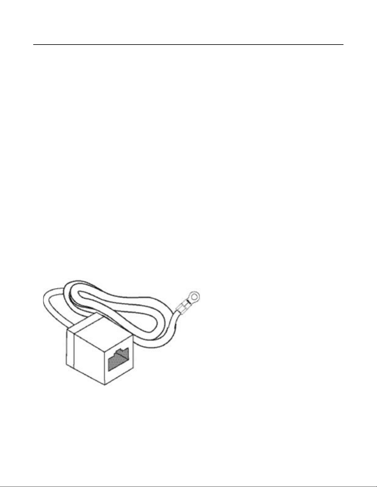
With new cable installations, you should use an ESD discharge cable to reduce the potential for
damage from static that can build up in cables. See the following figure.
Figure 3: ESD cable
May 2018 Installing Ethernet Routing Switch 4900 Series 15

Installation preparation
Technical specifications
The following table provides the technical specifications for the switches in this series. Ensure that
the area where you install the switch and where it operates meets these requirements.
Warning:
To avoid bodily injury from hazardous electrical shock and current, never remove the top of the
device. No user-serviceable components are inside.
Table 1: Physical specifications
Height 4.4 cm – 1RU
Width 17.32 inch (440 mm or 44 cm) - 19 inch rack
mountable
Depth 18.89 inch (480 mm or 48 cm)
Weight (switch weight with one PSU. Where, PSU
approximately weighs 1.6 kg)
• ERS4926GTS: 7.2 kg
• ERS4926GTS-PWR+: 7.9 kg
• ERS4950GTS: 7.3 kg
• ERS4950GTS-PWR+: 8.0 kg
Table 2: Environmental specifications
Operating Temperature 0° and 50° C (32° and 106° F)
Storage Temperature –40°C to 85°C (-40°F to 185°F)
Operating Humidity 0 to 95 percent non-condensing
Storage Humidity 0 to 95 percent non-condensing
Maximum Operating Altitude 3,048 m (10,000 feet) above sea level
Storage Altitude 0 to 12,192 m (0 to 40,000 feet) above sea level
Acoustic Noise At 25°C Ambient Temperature, less than 48 dBA
typical, at 50°C, less than 61 dBA.
Miscellaneous Operating Considerations • No nearby heat sources such as hot air vents or
direct sunlight
• No nearby sources of severe electromagnetic
noise
• No excessive dust
• Adequate power source within six feet; one circuit
required for each power supply (see table, AC
power specifications)
• At least 2 inches (5.08 cm) on each side of the
switch unit for ventilation
• Cables should be dressed to prevent blocking air
flow.
May 2018 Installing Ethernet Routing Switch 4900 Series 16

Power specifications
This section provides the following power specifications for the switch:
AC power specifications on page 17
•
• Typical power consumption on page 18
PoE+ budget calculations on page 18
•
The following table describes the AC power specifications.
Table 3: AC power specifications
Technical specifications
Model Number of
Power
supplies
Rated Line voltage Watts
ERS 4950GTS 1 250 W 200–240 VAC 53.14 0.30 181.31
2 250 W/PSU 200–240 VAC 58.88 0.44 200.89
1 250 W 100–110 VAC 53.67 0.51 183.12
2 250 W/PSU 100–110 VAC 59.53 0.58 203.11
ERS 4926GTS 1 250 W 200–240 VAC 39.37 0.25 134.33
2 250 W/PSU 200–240 VAC 46.23 0.40 157.73
1 250 W 100–110 VAC 39.43 0.38 134.53
2 250 W/PSU 100–110 VAC 44.35 0.46 151.32
ERS 4950GTSPWR+
ERS 4926GTSPWR+
1 1025 W 200–240 VAC 820.89 3.80 358.90
2 1025 W 200–240 VAC 1586.25 7.15 584.30
1 1025 W 100–110 VAC 842.10 7.75 431.95
2 1025 W 100–110 VAC 1660.07 15.15 837.88
1 1025 W 200–240 VAC 792.53 3.57 308.88
2 1025 W 200–240 VAC 816.03 3.78 342.32
1 1025 W 100–110 VAC 825.11 7.55 413.56
2 1025 W 100–110 VAC 839.64 7.73 424.24
Power supply Input power
(margined by 10%)
Amps
(Total)
Thermal
rating
(BTUs/hr
maximum)
The following table provides typical power consumption.
May 2018 Installing Ethernet Routing Switch 4900 Series 17
 Loading...