

Extreme Networks EAS 100-24t Switch, EAS 100-24t Hardware Installation Manual

Extreme Networks EAS 100-24t Switch
Hardware Installation Manual
Layer 2 Managed Gigabit Switch
Release 1.00
Extreme Networks, Inc.
3585 Monroe Street
Santa Clara, California 95051
(888) 257-3000
(408) 579-2800
http://www.extremenetworks.com
Published: July 2011
Part number: 120703-00 Rev. 01

AccessAdapt, Alpine, Altitude, BlackDiamond, Direct Attach, EPICenter, ExtremeWorks Essentials, Ethernet
Everywhere, Extreme Enabled, Extreme Ethernet Everywhere, Extreme Networks, Extreme Standby Router
Protocol, Extreme Turbodrive, Extreme Velocity, ExtremeWare, ExtremeWorks, ExtremeXOS, Go Purple Extreme
Solution, ExtremeXOS ScreenPlay, ReachNXT, Ridgeline, Sentriant, ServiceWatch, Summit, SummitStack, Triumph,
Unified Access Architecture, Unified Access RF Manager, UniStack, XNV, the Extreme Networks logo, the Alpine
logo, the BlackDiamond logo, the Extreme Turbodrive logo, the Summit logos, and the Powered by ExtremeXOS
logo are trademarks or registered trademarks of Extreme Networks, Inc. or its subsidiaries in the United States
and/or other countries.
sFlow is the property of InMon Corporation.
Specifications are subject to change without notice.
All other registered trademarks, trademarks, and service marks are property of their respective owners.
© 2011 Extreme Networks, Inc. All Rights Reserved.
2
Extreme Networks EAS 100-24t Switch Hardware Installation Manual

Table of Contents
Preface......................................................................................................................................................... 5
Intended Readers .....................................................................................................................................................5
Typographical Conventions......................................................................................................................................5
Notes, Cautions, and Warnings................................................................................................................................6
Safety Instructions....................................................................................................................................................6
Precautions .......................................................................................................................................................6
General Precautions for Rack-Mountable Products..........................................................................................8
Protecting Against Electrostatic Discharge...............................................................................................................9
Chapter 1: Introduction............................................................................................................................ 11
Ports .......................................................................................................................................................................11
LED Indicators........................................................................................................................................................12
Front-Panel Description..........................................................................................................................................13
Rear Panel Description ..........................................................................................................................................13
Side Panel Description ...........................................................................................................................................14
Gigabit Combo Ports ..............................................................................................................................................14
Chapter 2: Installation .............................................................................................................................. 17
Package Contents ..................................................................................................................................................17
Before You Connect to the Network.......................................................................................................................17
Installing the Switch without the Rack ....................................................................................................................18
Installing the Switch in a Rack................................................................................................................................18
Mounting the Switch in a Standard 19" Rack .........................................................................................................19
Power on AC Power........................................................................................................................................19
Power Failure ..................................................................................................................................................19
Chapter 3: Connecting the Switch .......................................................................................................... 21
Switch to End Node................................................................................................................................................21
Switch to Hub or Switch .........................................................................................................................................22
Chapter 4: Introduction to Switch Management....................................................................................23
Management Options .............................................................................................................................................23
Web-based Management Interface ........................................................................................................................23
SNMP-Based Management....................................................................................................................................23
Connecting the Console Port (RS-232 DCE) .........................................................................................................23
First Time Connecting to the Switch ......................................................................................................................25
Password Protection ..............................................................................................................................................25
SNMP Settings .......................................................................................................................................................26
Traps ...............................................................................................................................................................27
IP Address Assignment ..........................................................................................................................................27
Chapter 5: Web-Based Switch Configuration ........................................................................................31
Introduction.............................................................................................................................................................31
Login to Web Manager ...........................................................................................................................................31
Web-based User Interface .....................................................................................................................................32
Areas of the User Interface .............................................................................................................................32
Extreme Networks EAS 100-24t Switch Hardware Installation Manual
3

Table of Contents
Web Pages.............................................................................................................................................................34
Appendix A: Technical Specifications ................................................................................................... 35
General...................................................................................................................................................................35
Physical and Environmental ...................................................................................................................................37
Performance...........................................................................................................................................................37
LED Indicators........................................................................................................................................................37
Appendix B: Cables and Connectors ..................................................................................................... 39
Ethernet Cable .......................................................................................................................................................39
Console Cable........................................................................................................................................................40
4
Extreme Networks EAS 100-24t Switch Hardware Installation Manual

Preface
This manual describes the installation, maintenance, and configuration of the EAS 100-24t.
Intended Readers
The Extreme Networks EAS 100-24t Switch Hardware Installation Manual contains information for setup
and management of the switch. This manual is intended for network managers familiar with network
management concepts and terminology.
Typographical Conventions
Convention Description
[ ] In a command line, square brackets indicate an optional entry.
For example: [copy filename] means that optionally you can type copy
followed by the name of the file. Do not type the brackets.
Bold font Indicates a button, a toolbar icon, menu, or menu item.
For example: Click on the Apply button. Used for emphasis. May also indicate
system messages or prompts appearing on screen. For example: You have
mail. Bold font is also used to represent filenames, program names and
commands. For example: use the copy command.
Boldface Typewriter
Font
Initial capital letter Indicates a window name. Names of keys on the keyboard have initial
Menu Name > Menu Option Menu Name > Menu Option Indicates the menu structure.
Indicates commands and responses to prompts that must be typed exactly as
printed in the manual.
capitals.
For example: Click Enter.
Device > Port > Port Properties means the Port Properties menu option
under the Port menu option that is located under the Device menu.
Extreme Networks EAS 100-24t Switch Hardware Installation Manual
5

NOTE
CAUTION
WAR NING!
Preface
Notes, Cautions, and Warnings
A NOTE indicates important information that helps make better use of the device.
A CAUTION indicates either potential damage to hardware or loss of data and tells how to avoid the
problem.
A WARNING indicates a potential for property damage, personal injury, or death.
Safety Instructions
Use the following safety guidelines to ensure your own personal safety and to help protect your system
from potential damage. Throughout this document, the caution icon ( ) is used to indicate cautions
and precautions that you need to review and follow.
Precautions
To reduce the risk of bodily injury, electrical shock, fire, or damage to the equipment, observe the
following precautions.
● Observe and follow service markings.
● Do not service any product except as explained in your system documentation.
● Opening or removing covers that are marked with the triangular symbol with a lightning bolt
may expose you to electrical shock.
● Only a trained service technician should service components inside these compartments.
● If any of the following conditions occur, unplug the product from the electrical outlet and replace the
part or contact your trained service provider:
● The power cable, extension cable, or plug is damaged.
● An object has fallen into the product.
● The product has been exposed to water.
● The product has been dropped or damaged.
● The product does not operate correctly when you follow the operating instructions.
● Keep your system away from radiators and heat sources. Also, do not block cooling vents.
● Do not spill food or liquids on your system components, and never operate the product in a wet
environment.
6
Extreme Networks EAS 100-24t Switch Hardware Installation Manual

Safety Instructions
● Do not push any objects into the openings of your system. Doing so can cause fire or electric shock
by shorting out interior components.
● Use the product only with approved equipment.
● Allow the product to cool before removing covers or touching internal components.
● Operate the product only from the type of external power source indicated on the electrical ratings
label. If you are not sure of the type of power source required, consult your service provider or local
power company.
● To help avoid damaging your system, be sure the voltage on the power supply is set to match the
power available at your location:
● 115 volts (V)/60 hertz (Hz) in most of North and South America and some Far Eastern countries
such as South Korea and Taiwan
● 100 V/50 Hz in eastern Japan and 100 V/60 Hz in western Japan
● 230 V/50 Hz in most of Europe, the Middle East, and the Far East
● Also, be sure that attached devices are electrically rated to operate with the power available in your
location.
● Use only approved power cable(s). If you have not been provided with a power cable for your
system or for any AC-powered option intended for your system, purchase a power cable that is
approved for use in your country. The power cable must be rated for the product and for the voltage
and current marked on the product's electrical ratings label. The voltage and current rating of the
cable should be greater than the ratings marked on the product.
● To help prevent electric shock, plug the system and peripheral power cables into properly grounded
electrical outlets. These cables are equipped with three-prong plugs to help ensure proper
grounding. Do not use adapter plugs or remove the grounding prong from a cable. If you must use
an extension cable, use a 3-wire cable with properly grounded plugs.
● Observe extension cable and power strip ratings. Make sure that the total ampere rating of all
products plugged into the extension cable or power strip does not exceed 80 percent of the ampere
ratings limit for the extension cable or power strip.
● To help protect your system from sudden, transient increases and decreases in electrical power, use a
surge suppressor, line conditioner, or uninterruptible power supply (UPS).
● Position system cables and power cables carefully; route cables so that they cannot be stepped on or
tripped over. Be sure that nothing rests on any cables.
● Do not modify power cables or plugs. Consult a licensed electrician or your power company for site
modifications. Always follow your local/national wiring rules.
● When connecting or disconnecting power to hot-pluggable power supplies, if offered with your
system, observe the following guidelines:
● Install the power supply before connecting the power cable to the power supply.
● Unplug the power cable before removing the power supply.
● If the system has multiple sources of power, disconnect power from the system by unplugging all
power cables from the power supplies.
● Move products with care; ensure that all casters and/or stabilizers are firmly connected to the
system. Avoid sudden stops and uneven surfaces.
Extreme Networks EAS 100-24t Switch Hardware Installation Manual
7

NOTE
WARNING!
WARNING!
WARNING!
Preface
General Precautions for Rack-Mountable Products
Observe the following precautions for rack stability and safety. Also, refer to the rack installation
documentation accompanying the system and the rack for specific caution statements and procedures.
● Systems are considered to be components in a rack. Thus, “component” refers to any system as well
as to various peripherals or supporting hardware.
● Before working on the rack, make sure that the stabilizers are secured to the rack, extended to the
floor, and that the full weight of the rack rests on the floor. Install front and side stabilizers on a
single rack or front stabilizers for joined multiple racks before working on the rack.
● Always load the rack from the bottom up, and load the heaviest item in the rack first.
● Make sure that the rack is level and stable before extending a component from the rack.
● Use caution when pressing the component rail release latches and sliding a component into or out of
a rack; the slide rails can pinch your fingers.
● After a component is inserted into the rack, carefully extend the rail into a locking position, and then
slide the component into the rack.
● Do not overload the AC supply branch circuit that provides power to the rack. The total rack load
should not exceed 80 percent of the branch circuit rating.
● Ensure that proper airflow is provided to components in the rack.
● Do not step on or stand on any component when servicing other components in a rack.
A qualified electrician must perform all connections to DC power and to safety grounds. All electrical
wiring must comply with applicable local, regional or national codes and practices.
Never defeat the ground conductor or operate the equipment in the absence of a suitably installed
ground conductor. Contact the appropriate electrical inspection authority or an electrician if you are uncertain
that suitable grounding is available.
The system chassis must be positively grounded to the rack cabinet frame. Do not attempt to connect
power to the system until grounding cables are connected. A qualified electrical inspector must inspect
completed power and safety ground wiring. An energy hazard will exist if the safety ground cable is omitted or
disconnected.
Do not replace the battery with an incorrect type. The risk of explosion exists if the replacement battery
is not the correct lithium battery type. Dispose of used batteries according to the instructions.
8
Extreme Networks EAS 100-24t Switch Hardware Installation Manual

Protecting Against Electrostatic Discharge
Protecting Against Electrostatic Discharge
Static electricity can harm delicate components inside your system. To prevent static damage, discharge
static electricity from your body before you touch any of the electronic components, such as the
microprocessor. You can do so by periodically touching an unpainted metal surface on the chassis.
You can also take the following steps to prevent damage from electrostatic discharge (ESD):
1 When unpacking a static-sensitive component from its shipping carton, do not remove the
component from the antistatic packing material until you are ready to install the component in your
system. Just before unwrapping the antistatic packaging, be sure to discharge static electricity from
your body.
2 When transporting a sensitive component, first place it in an antistatic container or packaging.
3 Handle all sensitive components in a static-safe area. If possible, use antistatic floor pads, workbench
pads and an antistatic grounding strap.
Extreme Networks EAS 100-24t Switch Hardware Installation Manual
9

Preface
10
Extreme Networks EAS 100-24t Switch Hardware Installation Manual

Introduction
1
CHAPTER
Ports
The EAS 100-24t includes the following types of ports:
● Twenty 10/100/1000 BASE-TX ports
● Four 10/100/1000BASE-T/SFP combo ports
● One female DCE RS-232 DB-9 console port
The following table lists the features and compatibility for each type of port present in the EAS 100-24t.
SFP Combo: SFP Transceivers Supported:
• 10051: SX mini-GBIC - Mini-GBIC SFP, 1000BASE-SX, MMF 220 & 550 meters, LC
connector
• 10052: LX mini-GBIC - Mini-GBIC SFP, 1000BASE-LX, MMF 220 & 550 meters, SMF 10km,
LC connector
• 10056: 1000BASE-BX-D BiDi SFP - 1000BASE-BX-D SFP, 1490-nm TX/1310-nm RX
wavelength
• 10057: 1000BASE-BX-U BiDi SFP - 1000BASE-BX-U SFP, 1310-nm TX/1490-nm RX
wavelength
Compliant to following standards:
• IEEE 802.3z compliance
• IEEE 802.3u compliance
1000BASE-T
Combo:
100BASE-FX: IEEE 802.3 compliant
IEEE 802.3 compliant
IEEE 802.3u compliant
IEEE 802.3ab compliant
IEEE 802.3x flow control support in full-duplex
IEEE 802.3u compliant
IEEE 802.3x flow control support in full-duplex
Extreme Networks EAS 100-24t Switch Hardware Installation Manual
11
NOTE
Chapter 1: Introduction
The SFP combo ports on the switch cannot be used simultaneously with the corresponding 1000BASE-T
ports. If both ports are in use at the same time (ex. port 21 of the SFP and port 21 of the 1000BASE-T), the SFP
ports will take priority over the combo ports and render the 1000BASE-T ports inoperable.
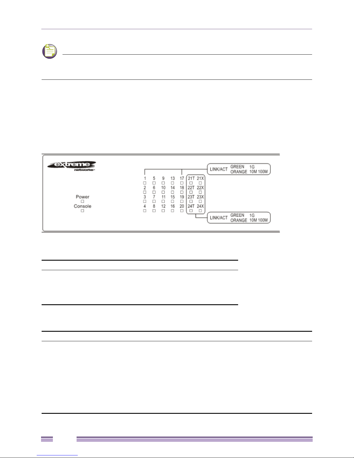
LED Indicators
The switch supports LED indicators for Power, Console, and Link/Act/Speed. The following shows the
LED indicators for the three switches along with an explanation of each indicator.
Figure 1: LED Indicators on EAS 100-24t Switch
Per Device:
LED Indicator Color Status Description
Power Green Solid Light Power ON
Light off Power OFF
Console Green Solid Light Console on
Light off Console off
EAS 100-24t (LED Per 10/100/1000 Mbps Port):
LED Indicator Color Status Description
Link/Act/Speed Green/
Orange
Solid Green When there is a secure 1000Mbps Ethernet connection
(or link) at any of the ports.
Blinking Green When there is reception or transmission (i.e. Activity—
Act) of data occurring at a Fast Ethernet connected
port.
Solid Orange When there is a secure 10/100Mbps Ethernet
connection (or link) at any of the ports.
Blinking Orange When there is reception or transmission (i.e. Activity—
Act) of data occurring at an Ethernet connected port.
Light off No link.
12
Extreme Networks EAS 100-24t Switch Hardware Installation Manual
 Loading...