

Extreme Networks E4G-200, E4G-200-12x, E4G-400 Installation Manual

E4G Routers Hardware
Installation Guide
121150-00
Published April 2016

Copyright © 2016 Extreme Networks All rights reserved.
Legal Notice
Extreme Networks, Inc. reserves the right to make changes in specifications and other information
contained in this document and its website without prior notice. The reader should in all cases
consult representatives of Extreme Networks to determine whether any such changes have been
made.
The hardware, firmware, software or any specifications described or referred to in this document
are subject to change without notice.
Trademarks
Extreme Networks and the Extreme Networks logo are trademarks or registered trademarks of
Extreme Networks, Inc. in the United States and/or other countries.
All other names (including any product names) mentioned in this document are the property of
their respective owners and may be trademarks or registered trademarks of their respective
companies/owners.
For additional information on Extreme Networks trademarks, please see:
www.extremenetworks.com/company/legal/trademarks/
Support
For product support, including documentation, visit: www.extremenetworks.com/documentation/
For information, contact:
Extreme Networks, Inc.
145 Rio Robles
San Jose, California 95134
USA

Table of Contents
Preface......................................................................................................................................... 5
Audience....................................................................................................................................................................................5
Conventions.............................................................................................................................................................................5
Getting Help............................................................................................................................................................................ 6
Providing Feedback to Us.................................................................................................................................................7
Related Publications............................................................................................................................................................ 7
Chapter 1: Extreme Networks E4G Series Routers................................................................9
E4G-200 Cell Site Routers..............................................................................................................................................10
E4G-400 Cell Site Aggregation Router................................................................................................................... 14
Pluggable Interfaces for E4G Series Routers.........................................................................................................21
Stacking Options for E4G Series Routers.............................................................................................................. 22
Chapter 2: Site Preparation.................................................................................................... 23
Planning Your Site..............................................................................................................................................................23
Meeting Site Requirements........................................................................................................................................... 24
Evaluating and Meeting Cable Requirements...................................................................................................... 29
Meeting Power Requirements......................................................................................................................................34
Following Applicable Industry Standards.............................................................................................................. 36
Chapter 3: Installing an E4G Series Router..........................................................................38
Pre-installation Requirements...................................................................................................................................... 38
Installing an E4G-200 Cell Site Router....................................................................................................................38
Installing an E4G-400 Cell Site Aggregation Router....................................................................................... 46
First-Time Startup..............................................................................................................................................................63
Chapter 4: Maintaining Your Equipment..............................................................................64
Replacing an AC Power Supply.................................................................................................................................. 64
Replacing a DC Power Supply.....................................................................................................................................66
Replacing a Fan Module...................................................................................................................................................71
Replacing Optional Ports................................................................................................................................................72
Replacing a Clock Module..............................................................................................................................................73
Replacing a T1/E1 Module...............................................................................................................................................74
Removing an E4G-200 Router from an Equipment Rack..............................................................................75
Removing an E4G-400 Router from an Equipment Rack............................................................................. 76
Appendix A: Safety Information............................................................................................78
Safety Considerations Before Installing...................................................................................................................79
General Safety Precautions...........................................................................................................................................79
Maintenance Safety...........................................................................................................................................................80
Cable Routing for LAN Systems.................................................................................................................................80
Installing Power Supply Units and Connecting Power......................................................................................81
Selecting Power Supply Cords.................................................................................................................................... 82
Battery Replacement and Disposal...........................................................................................................................83
Fiber Optic Ports and Optical Safety.......................................................................................................................83
Safety Information for the E4G Series Routers...................................................................................................84
Sicherheitshinweise...........................................................................................................................................................84
Überlegungen vor der Installation............................................................................................................................. 84
Allgemeine Sicherheitshinweise..................................................................................................................................85
E4G Routers Hardware Installation Guide 3

Table of Contents
Sicherheit bei Wartungsarbeiten................................................................................................................................86
Kabelverlegung für LAN-Systeme............................................................................................................................. 86
Installation der Netzteile und Netzanschluss........................................................................................................87
Auswahl der Netzkabel....................................................................................................................................................89
Wechseln und Entsorgen der Batterie.....................................................................................................................89
LWL-Ports und optische Sicherheit.......................................................................................................................... 89
Sicherheitsinformationen für Router der Serie E4G.........................................................................................90
Appendix B: Technical Specifications................................................................................... 91
E4G-200 Cell Site Router Technical Specifications............................................................................................91
E4G-400 Cell Site Aggregation Router Technical Specifications.............................................................. 96
Power Supplies for the E4G-400 Router..............................................................................................................103
E4G-200 Connector Pinouts...................................................................................................................................... 106
E4G-400 Connector Pinouts......................................................................................................................................109
Conformity Statements...................................................................................................................................................112
Index..........................................................................................................................................116
E4G Routers Hardware Installation Guide 4
Preface
Audience
This guide is intended for network administrators and equipment installers who are responsible for
installing and setting up network equipment.
This guide assumes a basic working knowledge of:
Standard equipment installation procedures, including remote location and electrical safety
•
practices
Local area networks (LANs)
•
Ethernet concepts
•
Ethernet switching and bridging concepts
•
Routing concepts
•
Time division multiplexing (TDM)
•
Simple Network Management Protocol (SNMP)
•
See the ExtremeXOS User Guide and the ExtremeXOS Command Reference Guide for information about
configuring Extreme Networks E4G series routers.
Note
If the information in an installation note or release note shipped with your Extreme Networks
equipment diers from the information in this guide, follow the installation or release note.
Conventions
This section discusses the conventions used in this guide.
Text Conventions
The following tables list text conventions that are used throughout this guide.
Table 1: Notice Icons
Icon Notice Type Alerts you to...
General Notice Helpful tips and notices for using the product.
Note Important features or instructions.
Caution Risk of personal injury, system damage, or loss of data.
E4G Routers Hardware Installation Guide 5
Table 1: Notice Icons (continued)
Icon Notice Type Alerts you to...
Warning Risk of severe personal injury.
New This command or section is new for this release.
Table 2: Text Conventions
Convention Description
Preface
Screen displays
The words enter and
type
[Key] names Key names are written with brackets, such as [Return] or [Esc]. If you must press two
Words in italicized type Italics emphasize a point or denote new terms at the place where they are defined in
This typeface indicates command syntax, or represents information as it appears on the
screen.
When you see the word “enter” in this guide, you must type something, and then press
the Return or Enter key. Do not press the Return or Enter key when an instruction
simply says “type.”
or more keys simultaneously, the key names are linked with a plus sign (+). Example:
Press [Ctrl]+[Alt]+[Del]
the text. Italics are also used when referring to publication titles.
Platform-Dependent Conventions
Unless otherwise noted, all information applies to all platforms supported by ExtremeXOS software,
which are the following:
ExtremeSwitching® switches
•
Summit® switches
•
SummitStack
•
When a feature or feature implementation applies to
the heading for the section describing that implementation in the ExtremeXOS Command Reference
Guide. In many cases, although the command is available on all platforms, each platform uses specific
keywords. These keywords specific to each platform are shown in the Syntax Description and discussed
in the Usage Guidelines.
™
specific platforms, the specific platform is noted in
Terminology
When features, functionality, or operation is specific to a switch family, such as ExtremeSwitching or
Summit, the family name is used. Explanations about features and operations that are the same across
all product families simply refer to the product as the switch.
Getting Help
If you require assistance, you can contact Extreme Networks using one of the following methods:
E4G Routers Hardware Installation Guide 6

Global Technical Assistance Center (GTAC) for Immediate Support
•
Phone: 1-800-872-8440 (toll-free in U.S. and Canada) or 1-603-952-5000. For the Extreme
•
Networks support phone number in your country, visit: www.extremenetworks.com/support/
contact
Email: support@extremenetworks.com. To expedite your message, enter the product name or
•
model number in the subject line.
GTAC Knowledge — Get on-demand and tested resolutions from the GTAC Knowledgebase, or
•
create a help case if you need more guidance.
The Hub — A forum for Extreme customers to connect with one another, get questions answered,
•
share ideas and feedback, and get problems solved. This community is monitored by Extreme
Networks employees, but is not intended to replace specific guidance from GTAC.
Support Portal — Manage cases, downloads, service contracts, product licensing, and training and
•
certifications.
Before contacting Extreme Networks for technical support, have the following information ready:
Your Extreme Networks service contract number and/or serial numbers for all involved Extreme
•
Network products
A description of the failure
•
A description of any action(s) already taken to resolve the problem
•
A description of your network environment (such as layout, cable type, other relevant environmental
•
information)
Network load at the time of trouble (if known)
•
The device history (for example, if you have returned the device before, or if this is a recurring
•
problem)
Any related Return Material Authorization (RMA) numbers
•
Preface
Providing Feedback to Us
We are always striving to improve our documentation and help you work better, so we want to hear
from you! We welcome all feedback but especially want to know about:
Content errors or confusing or conflicting information.
•
Ideas for improvements to our documentation so you can find the information you need faster.
•
Broken links or usability issues.
•
If you would like to provide feedback to the Extreme Networks Information Development team about
this document, please contact us using our short online feedback form. You can also email us directly at
internalinfodev@extremenetworks.com.
Related Publications
Hardware Documentation
ExtremeSwitching X8 Series Switches Hardware Installation Guide
•
Summit Family Switches Hardware Installation Guide for Switches Using ExtremeXOS 21.1
•
Summit Family Switches Hardware Installation Guide for Switches Using ExtremeXOS 16 and Earlier
•
E4G Routers Hardware Installation Guide 7

E4G Series Routers Hardware Installation Guide
•
Extreme Hardware/Software Compatibility and Recommendation Matrices
•
Extreme Networks Pluggable Transceivers Installation Guide
•
Preface
E4G Routers Hardware Installation Guide 8

1 Extreme Networks E4G Series
Routers
E4G-200 Cell Site Routers
E4G-400 Cell Site Aggregation Router
Pluggable Interfaces for E4G Series Routers
Stacking Options for E4G Series Routers
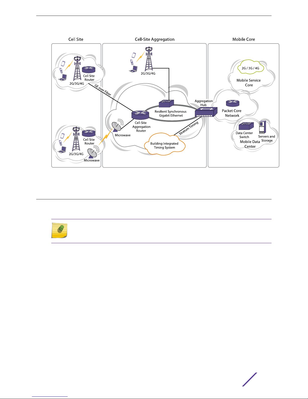
The Extreme Networks E4G router family consists of the E4G-200 cell site routers (models E4G-200
and E4G-200-12x) and the E4G-400 cell site aggregation router.
These routers provide high-bandwidth capacity, highly accurate and
Administration and Maintenance (OAM) capabilities that support service level agreement (SLA) metrics.
They support time-division multiplexing pseudowire end-to-end emulation (TDM PWE3). PWE allows
the simultaneous support of multiple generations of services (2G, 3G, and 4G) over the same Ethernet
backhaul network without having to remove legacy T1/E1 equipment and incur associated costs.
Note
Unless otherwise noted, the term E4G-200 refers in this document to both models in the
E4G-200 series: the E4G-200 and the E4G-200-12x.
The E4G-200 cell site router collects trac from cell site towers for hando to the mobile backhaul
network. The E4G-200 router connects to the E4G-400 cell site aggregation router, which aggregates
T1, E1, and Ethernet trac for hando to the mobile core.
flexible timing, and Operations
E4G Routers Hardware Installation Guide 9
Extreme Networks E4G Series Routers
Figure 1: Mobile Backhaul Architecture
E4G-200 Cell Site Routers
The Extreme Networks E4G-200 routers provide 12 resilient synchronous Gigabit Ethernet ports and 16
T1/E1 ports in a compact (1RU or 1.75 inches high) unit.
Note
Unless otherwise noted, the term E4G-200 refers in this document to both models in the
E4G-200 series: the E4G-200 and the E4G-200-12x.
The Ethernet ports support both IEEE 1588v2 and Synchronous Ethernet (SyncE) timing, and the T1/E1
ports support time division multiplexing (TDM) timing. The router provides high-performance
pseudowire capability, supporting both CESoPSN (channelized) and SAToP (unframed and
unchannelized) TDM services. Deployed at the cell site, the E4G-200 cell site router collects trac from
2G, 3G, and 4G radio towers for hando to the mobile backhaul over fiber or microwave.
The E4G-200 extended temperature range of -40°C to +65°C allows service providers to deploy the
E4G-200 router at sites without climate control.
Features:
Management and console ports
•
Eight 10/100/1000BASE-T (RJ-45) dedicated ports
•
Four 100/1000BASE-X (SFP) ports
•
These ports require Extreme Networks optical modules that are designed for use within the
temperature range of the router.
Slot for clock module
•
E4G Routers Hardware Installation Guide 10
Extreme Networks E4G Series Routers
Slot for T1/E1 module with 16 ports
•
Grounding lug
•
Redundant DC input power connectors
•
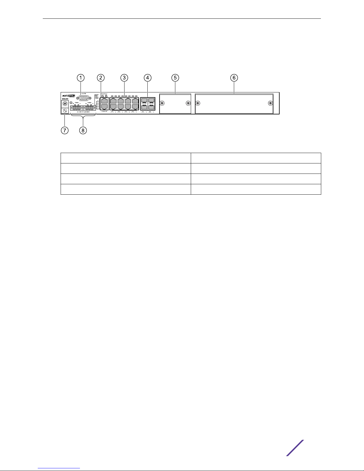
Figure 2: E4G-200 Cell Site Router Front Panel
1 = Alarms connection (inactive) 5 = Slot for E4G-200 CLK module
2 = Management and console ports 6 = Slot for F16T1E1 module
3 = RJ-45 dedicated ports 7 = Grounding lug
4 = SFP ports 8 = DC input power connectors
The E4G-200 router has an integrated DC power supply with dual feeds on the front panel. Power feed
A can be connected to one power source and power feed B can be connected to a dierent power
source to provide protection should either source of power fail. The power supply is not field-
replaceable.
The back panel of the E4G-200 router provides an alternate attachment point for the grounding lug.
Status LEDs on the E4G-200 router are described in Table 3: System LEDs on page 13.
E4G-200 Power Supply
The E4G-200 router has an integrated DC power supply with dual feeds on the front panel. Power feed
A can be connected to one power source and power feed B can be connected to a dierent power
source to provide protection should either source of power fail. The power supply is not field-
replaceable.
The back panel of the E4G-200 router provides an alternate attachment point for the grounding lug.
E4G-200 Clock (CLK) Module
An optional clock module for the E4G-200 router provides timing. Timing is based on either:
ITU-T Synchronous Ethernet (SyncE) protocol
•
Precision Time Protocol based on the IEEE specification 1588v2
•
The clock module has four mini-BNC connectors providing Sync In/Sync Out timing interfaces and an
RJ-45 connector that provides an RS-422 BITS-IN interface. Clock modules can be installed or removed
without powering down the router, although a system reboot is required to initialize the module.
E4G Routers Hardware Installation Guide 11
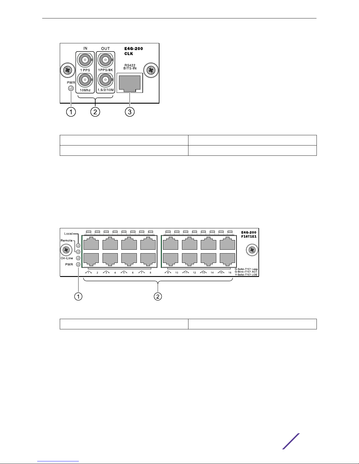
Figure 3: E4G-200 Clock Module
1 = LED 3 = BITS IN interface
2 = Sync In/Sync Out interfaces
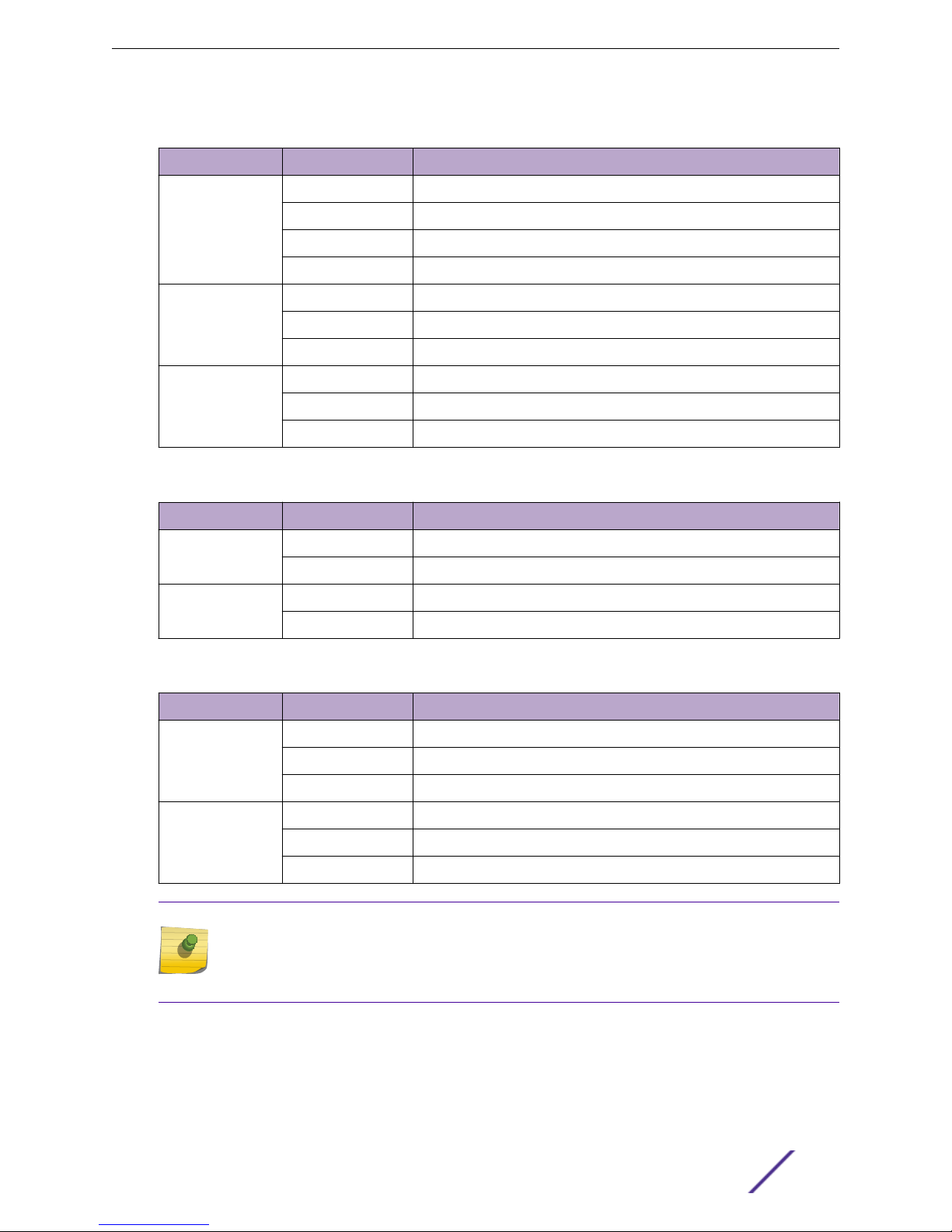
E4G-200 F16T1E1 Module
Extreme Networks E4G Series Routers
The F16T1E1 module for the E4G-200 router provides 16 T1/E1 ports implemented as RJ-45 connectors.
These ports support circuit emulations over industry-standard pseudowires, allowing the transformation
of TDM cell sites to Ethernet/IP/MPLS cell sites. T1/E1 modules can be installed or removed without
powering down the router, although a system reboot is required to initialize the module.
Figure 4: E4G-200 F16T1E1 Module
1 = LEDs
2 = T1/E1 ports
E4G-200 LEDs
The following tables describe the LEDs on the E4G-200 cell site router (models E4G-200 and
E4G-200-12x).
E4G Routers Hardware Installation Guide 12
Extreme Networks E4G Series Routers
Table 3: System LEDs
Label/type Color/State Meaning
MGMT Steady green Power-on self- test (POST) passed, normal operation
Blinking green POST in progress
Amber POST failed or system has overheated
O No power
FAN Steady green Normal operation
Blinking amber Failure
O No power
PSU-1, PSU-2 Steady green Normal operation
Blinking amber Power failure
O No power attached to this connector
Table 4: MGMT Port LEDs
Label/type Color/State Meaning
ACT Blinking green Packet transmitting or receiving
O No packet transmitting or receiving
LINK Blinking green Link up
O No link or port disabled
Table 5: Port LEDs
Label/type Color/State Meaning
Ports 1 – 8
(see note)
Ports 9 – 12
(see note)
Steady green Link exists
Blinking green Activity occurring
O No link or port is disabled
Steady green Link exists
Blinking green Activity occurring
O No link or port is disabled
Note
On model E4G-200 routers, LEDs for ports 1 – 8 are located above the ports and LEDs for
ports 9 – 12 are located on SFP cages.
On model E4G-200-12x routers, LEDs for ports 1 – 12 are located on SFP cages.
E4G Routers Hardware Installation Guide 13
Table 6: Clock Module LED
Label/type Color/State Meaning
PWR Steady green 3.3 V power OK
O No power
Table 7: F16T1E1 Module LEDs
Label/type Color/State Meaning
Extreme Networks E4G Series Routers
Local
(Alarm LED)
Remote
(Alarm LED)
On-Line Steady green On line
PWR Steady green Normal operation
Port LEDs (1 – 16) Steady green Link OK
Steady green Local alarm active
Blinking green Local alarm active but silenced
O No local alarm active
Steady green Remote alarm active
Blinking green Remote alarm active but silenced
O No remote alarm active
O O line
O No power
Blinking green Activity
O No link, or port is disabled
E4G-400 Cell Site Aggregation Router
The E4G-400 cell site aggregation router is a compact unit (1RU or 1.75 inches high) that enables
networks to aggregate multiple Ethernet links from various cell sites and route the trac to the mobile
core.
The E4G-400 router provides 28 Gigabit Ethernet ports and port options for up to six 10-Gigabit
Ethernet ports, as well as a 16-port T1/E1 module with pseudowire capability. The T1/E1 module is used
where 2G and 3G radios are co-located at the aggregation site, and eliminates the need for separate cell
site routers.
The Gigabit and 10-Gigabit Ethernet ports on the E4G-400 router support Synchronous Ethernet
(SyncE) and IEEE 1588v2 timing. Integrated timing connectors on the front panel provide timing based
on either the ITU-T Synchronous Ethernet (SyncE) protocol or the Precision Time Protocol based on
IEEE specification 1588v2. Four mini-BNC connectors providing Sync In/Sync Out timing interfaces and
an RJ-422 connector provides a BITS-IN interface.
The E4G-400 router has 4 shared ports. For each pair of shared ports, either the 10/100/1000BASE-T
port (RJ45) or 100/1000BASE-X (SFP) port can be used as needed.
E4G Routers Hardware Installation Guide 14
Extreme Networks E4G Series Routers
The E4G-400 router supports stacking using ports on installed port option cards at the back of the unit.
Up to eight units can be connected into a single management entity that has up to 192 Gigabit Ethernet
ports and up to 32 10-Gigabit Ethernet ports.
At the back of the unit are two bays for either AC or DC power supplies. One 300 W AC or DC power
supply is included with the base unit. A redundant power supply must be ordered separately. You can
mix any combination of 300 W AC and DC power supplies based on the need at the particular site. For
example, you can have a DC main power feed and an AC input backup from an uninterruptible power
supply (UPS).
The front panel of the E4G-400 router has the following features:
Twenty 10/100/1000BASE-T (RJ-45) dedicated ports
•
Four 100/1000BASE-X (SFP) or 10/100/1000BASE-T (RJ-45) shared ports
•
Four 100/1000BASE-X (SFP) dedicated ports
•
Timing interfaces
•
BITS-IN interface
•
Console port
•
Stack number indicator
•
Management and USB ports
•
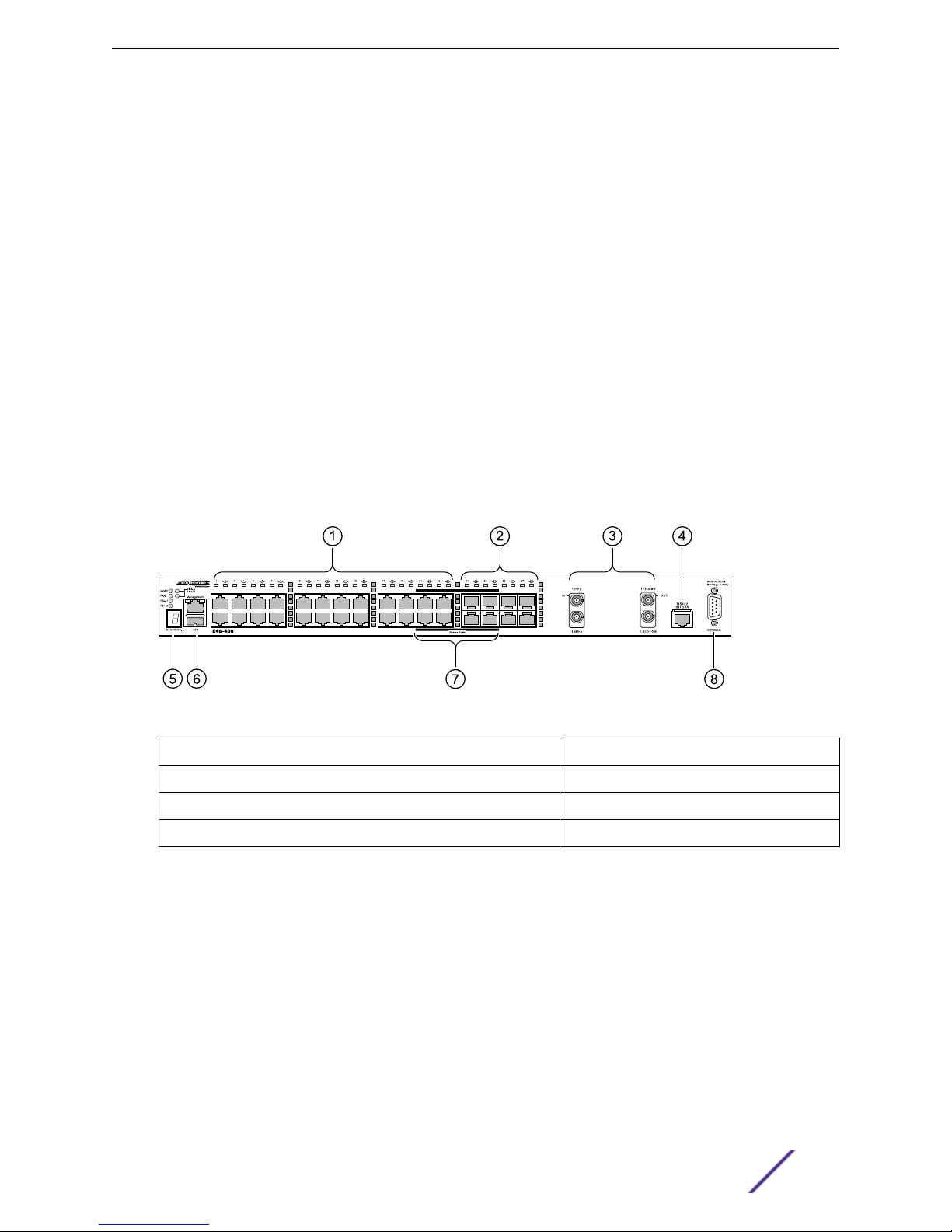
Figure 5: E4G-400 Front Panel
1 = RJ-45 ports
2 = SFP ports 6 = Management and USB ports
3 = Timing connections (Mini-BNC connectors) 7 = Shared ports
4 = BITS IN connector (RJ-45 connector) 8 = Console port
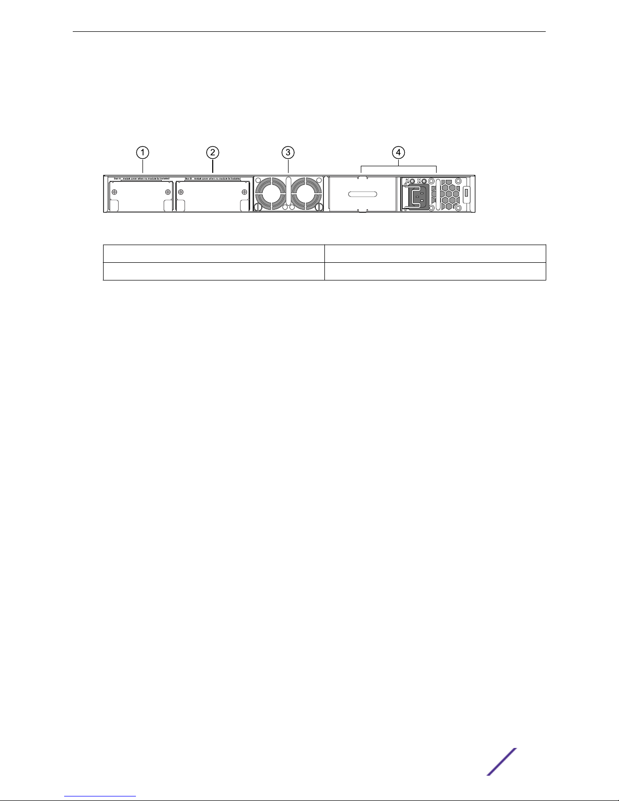
The rear panel of the E4G-400 router (Figure 6: E4G-400 Back Panel on page 16) has the following
features:
Slot A for one of the following optional cards:
•
XGM3S-2xf option card (2 XFP with Sync-E for stacking or data links)
•
XGM3S-2sf option card (2 SFP+ with Sync-E for stacking or data links)
•
Slot B for one of the following optional cards:
•
XGM3SB-4sf option card (4 SFP+ with Sync-E for data links)
•
E4G-B16T1E1 module (2 MRJ21 with 8 TDM ports per MRJ21 connector)
•
Cards in Slot A and Slot B are hot-pluggable.
5 = Stack number indicator
E4G Routers Hardware Installation Guide 15
Extreme Networks E4G Series Routers
Hot-swappable fan tray
•
Two bays for AC or DC power supplies
•
To provide redundant power to the router, you can install two AC power supplies, two DC power
supplies, or a combination of an AC and DC power supply.
Figure 6: E4G-400 Back Panel
1 = Slot A 3 = Fan tray
2 = Slot B 4 = Power supply bays
E4G-400 Combination Ports
The E4G-400 cell site aggregation router provides four uplink ports implemented as combination ports
that pair a copper port using RJ-45 connectors with an optical port using LC connectors.
The copper port operates as an autonegotiating 10/100/1000BASE-T port. The optical port allows
Gigabit Ethernet uplink connections through Extreme Networks small form factor pluggable (SFP)
interface modules.
The E4G-400 router supports automatic failover from an active fiber port to a copper backup or from
an active copper port to a fiber port. If one of the uplink connections fails, the uplink connection
automatically fails over to the second connection. To set up a redundant link on a combination port,
connect the active 1000BASE-T and fiber links to both the RJ-45 and SFP interfaces of that port.
Gigabit Ethernet uplink redundancy on the E4G-400 router follows these rules:
With both the SFP and 1000BASE-T interfaces connected on a combination port, only one interface
•
can be activated. The other is inactive.
If only one interface is connected, the router activates the connected interface.
•
The router determines whether the port uses the fiber or copper connection based on the order in
•
which the connectors are inserted into the router. When the router senses that an SFP and a copper
connector are inserted, the router enables the uplink redundancy feature. For example, if you first
connect copper ports 21 and 22, and then insert SFPs into optical ports 21 and 22, the router assigns
the copper ports as active ports and the fiber ports as redundant ports.
Hardware identifies when a link is lost and responds by swapping the primary and redundant ports to
maintain stability. After a failover occurs, the router keeps the current port assignment until another
failure occurs or a user changes the assignment using the CLI. For more information about configuring
automatic failover on combination ports, see the ExtremeXOS User Guide.
E4G-400 LEDs
The following tables describe the LEDs on the E4G-400 cell site aggregation router.
E4G Routers Hardware Installation Guide 16
Extreme Networks E4G Series Routers
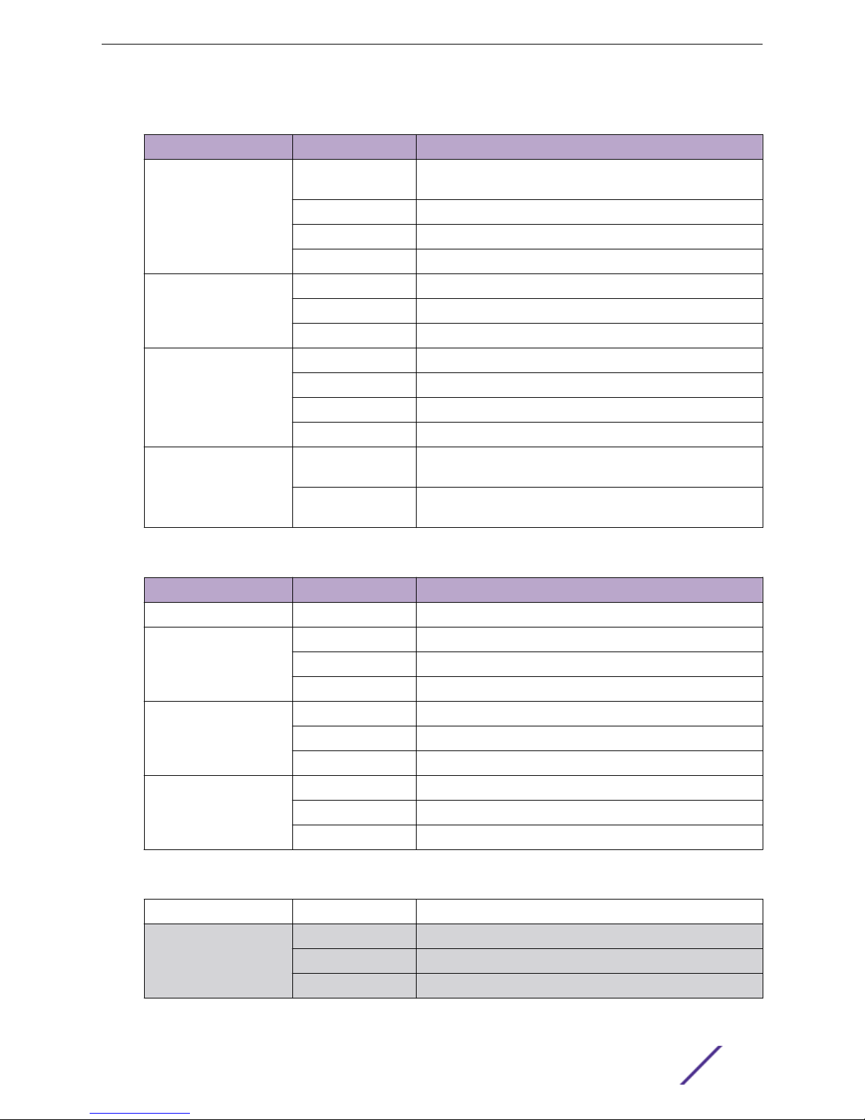
Table 8: Front Panel LEDs
Type/Label Color/State Meaning
MGMT Steady green Power-on self test (POST) completed successfully; normal
operation
Blinking green POST is in progress
Amber POST failed, or the system has overheated
O No external power attached
FAN Steady green Normal operation
Blinking amber Failure
O No power
PSU-1, PSU-2 Steady green Normal operation
Steady amber Power is attached, but no power is on
Blinking amber Failure
O No power is attached
Slot-A, Slot-B Steady green Port option card is installed in the indicated slot at the back of
the router
O No port option card is installed in the indicated slot at the back
of the router
Table 9: 2-digit Stack Number Indicator
Type/Label Color/State Meaning
Left digit (1) NA Reserved for future use
Right digit (1 – 8)
Indicates the position of
this router in a stacked
configuration.
Ethernet Ports 1 – 28 Steady green Link OK
Management Port Steady green Link OK
Upper half blinking This router is the stack master node
Lower half blinking This router is the stack backup node
Lit steadily This router is a standby node in the stack
Blinking green Activity
O No link, or port is disabled
Blinking green Activity
O No link, or port is disabled
Table 10: Back Panel
Type/Label Color/State Meaning
Port LED on installed
XGM3S-2sf option card
E4G Routers Hardware Installation Guide 17
Steady green Link OK
Blinking green Activity
O No link, or port is disabled
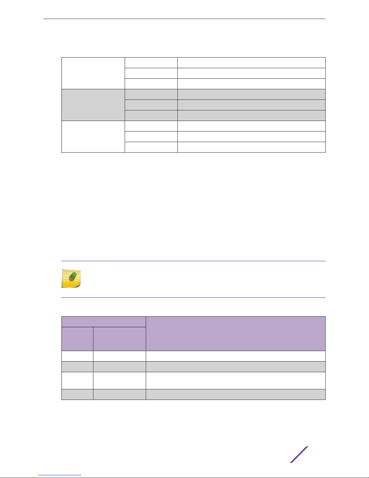
Table 10: Back Panel (continued)
Port LED on installed
XGM3S-2xf option card
Steady green Link OK
Blinking green Activity
O No link, or port is disabled
Extreme Networks E4G Series Routers
Port LED on installed
XGM3SB-4xf option card
(S1 – S4)
Port LED on installed
E4G-B16T1E1 module (1 –
16)
Steady green Link OK
Blinking green Activity
O No link, or port is disabled
Steady green Link OK
Blinking green Activity
O No link, or port is disabled
E4G-400 Power Supplies
The E4G-400 router is compatible with the following power supplies:
300 W AC power supply (model number 10930A)
•
300 W DC power supply (model number 10934A)
•
300 W DC power supply (model number 10933)
•
An E4G-400 router accommodates one or two 300 W power supplies. You can combine AC and DC
power supplies in the same E4G-400 router. In a redundant power configuration, both power supplies
are fully fault-tolerant and load-sharing. You can remove one power supply without interrupting router
operation.
Note
An AC power input cord is not provided with a 300 W AC power supply. You can order an
appropriate cord from Extreme Networks or from your local supplier. The power cord must
meet the requirements listed in Power Supplies for the E4G-400 Router on page 103.
Table 11: 300 W AC Power Supply LEDs
LED Label and Color Meaning
AC IN
OK
Green
O O No AC input power
O Steady red No AC input power; receiving standby output from system
On O AC input good; 12 V output is disabled
On Steady red AC input good; fault in 12 V output
E4G Routers Hardware Installation Guide 18
DC Out
OK
Green/red bicolor
Standby output is ON
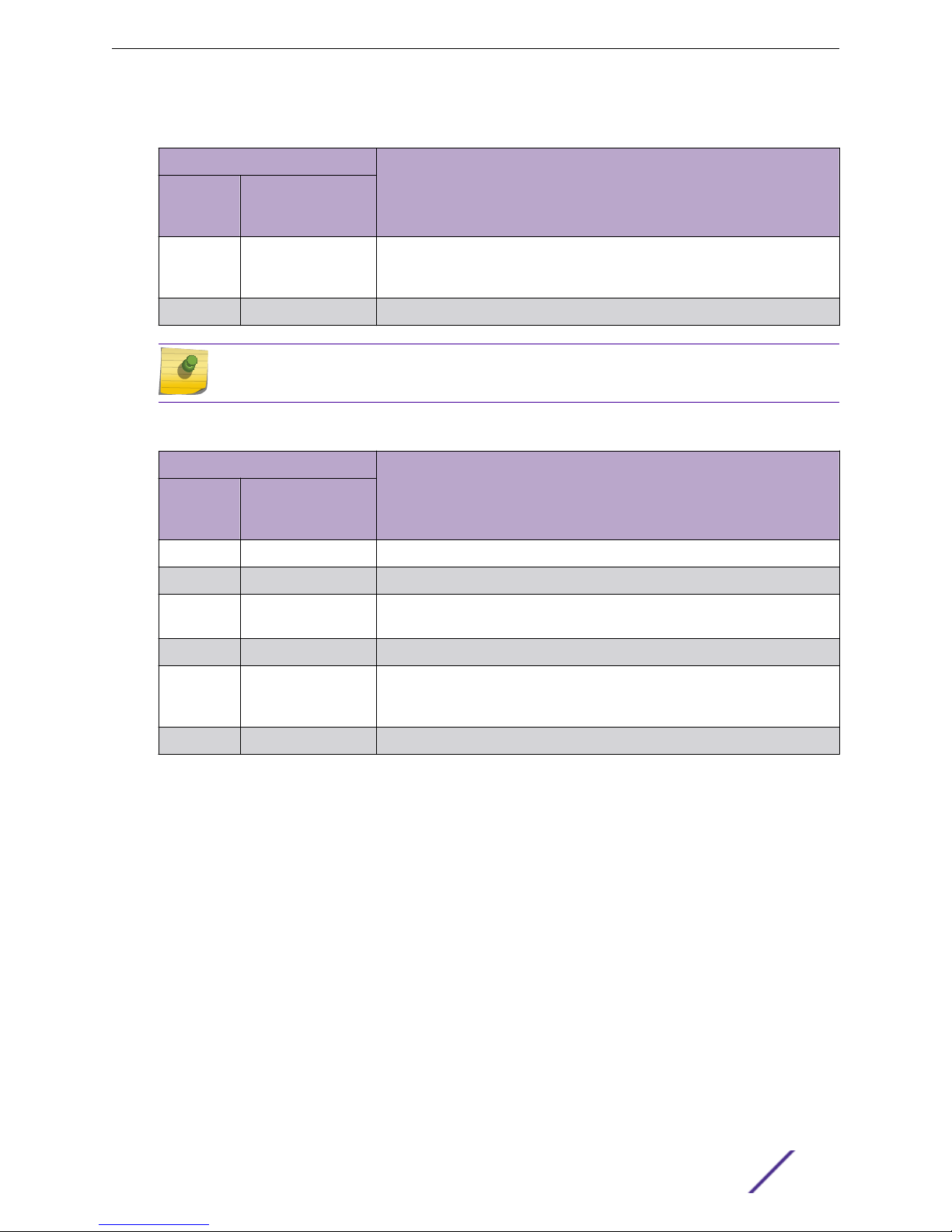
Table 11: 300 W AC Power Supply LEDs (continued)
LED Label and Color Meaning
Extreme Networks E4G Series Routers
AC IN
OK
Green
On Flashing green and
On Steady green AC input good; DC outputs good
DC Out
OK
Green/red bicolor
red
AC input good, 12 V output good
Power supply alert: power supply is likely to fail because of a developing
fault, such as abnormal thermal conditions or poor fan performance
Note
The model 10933 is the recommended DC power supply.
Table 12: 300 W DC Power Supply (models 10934A and 10933) LEDs
LED Label and Color Meaning
AC IN
OK
Green
O O No DC input power
O Steady red No DC input power; receiving standby output from system
On O DC input is good; 12 V output is disabled
DC Out
OK
Green/red bicolor
Standby output is ON
On Steady red DC input is good; fault in 12 V output
On Flashing green and
red
On Steady green DC input is good; DC outputs are good
DC input is good, 12 V output is good
Power supply alert: power supply is likely to fail because of a developing
fault, such as abnormal thermal conditions or poor fan performance
Optional Port Cards for the E4G-400 Router
The rear panel of the E4G-400 router has two slots for installing optional port cards.
Slot A accommodates either of the following option cards:
XGM3S-2sf Option Card on page 19
•
XGM3S-2xf Option Card on page 20
•
Slot B accommodates either of the following option cards:
XGM3SB-4sf Option Card on page 20
•
E4G-B16T1E1 Module on page 21
•
XGM3S-2sf Option Card
The XGM3S-2sf option card allows you to add one or two 10-Gigabit SFP+ optical ports to slot A on the
rear panel of an E4G-400 router.
E4G Routers Hardware Installation Guide 19

Extreme Networks E4G Series Routers
These ports support synchronous Ethernet and can be used for stacking connections or data links. The
XGM3S-2sf option card supports either SFP+ optical modules or an SFP+ direct-attach passive copper
cable.
Figure 7: XGM3S-2sf Option Card
1 = SFP+ ports 2 = LEDs
XGM3S-2xf Option Card
The XGM3S-2xf option card allows you to add one or two 10-Gigabit XFP optical ports to Slot A on the
rear panel of the E4G-400 router.
These ports support synchronous Ethernet and can be used for stacking connections or data links.
Figure 8: XGM3S-2xf Option Card
1 = XFP ports
2 = LEDs
XGM3SB-4sf Option Card
The XGM3SB-4sf option card allows you to add up to four 10-Gigabit SFP+ optical ports to Slot B on the
rear panel of the E4G-400 router.
These ports support synchronous Ethernet and can be used for data links. The XGM3SB-4sf option card
supports either SFP+ optical modules or the SFP+ direct-attach passive copper cable.
Figure 9: XGM3SB-4sf Option Card
E4G Routers Hardware Installation Guide 20
Extreme Networks E4G Series Routers
1 = SFP+ ports 2 = LEDs
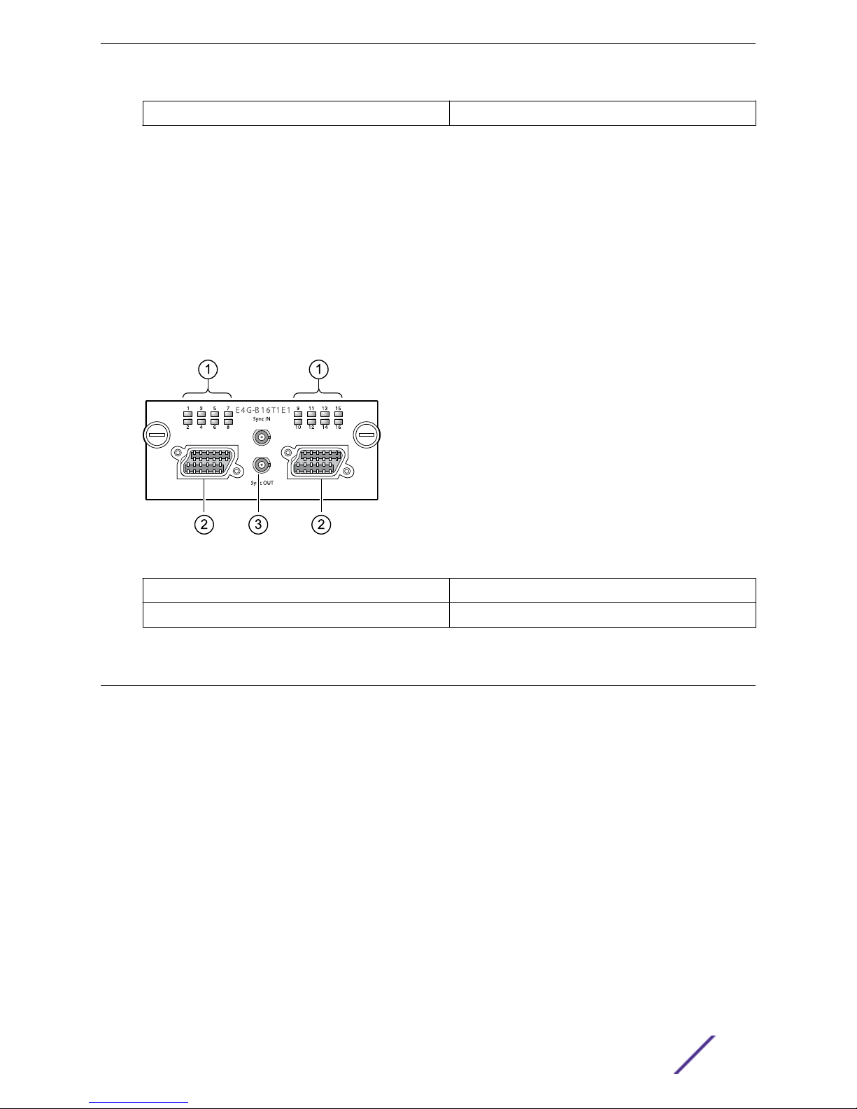
E4G-B16T1E1 Module
The E4G-B16T1E1 module allows you to add 16 T1/E1 ports with pseudowire emulation to slot B on the
rear panel of the E4G-400 router.
This module has two MRJ21 connectors, each one providing eight ports. Connections to these
connectors are made in either of the following ways:
A special fan-out cable that connects to the module and provides eight separate RJ-45 connectors
•
at the other end. (See E4G-400 Connector Pinouts on page 109 for more information about this
cable.)
A straight MRJ21-to-MRJ21 cable that connects to a breakout panel
•
Figure 10: E4G-B16T1E1 Module
1 = T1/E1 ports
2 = MRJ21 connectors
3 = Sync In/Sync Out interfaces
Pluggable Interfaces for E4G Series Routers
Ports on E4G series routers are compatible with a variety of optical modules, including SFP, SFP+, and
XFP modules.
Extreme Networks optical modules are tested to work in all supported Extreme Networks devices. We
recommend that all customers use Extreme Networks optical modules in their Extreme Networks
devices. Extreme Networks assumes no liability for third-party optical modules. Although Extreme
Networks does not block third-party optical modules, we cannot ensure that all third-party optical
modules operate properly in all Extreme Networks devices. The customer assumes all risks associated
with using third-party optical modules in Extreme Networks devices.
For details about which optical modules are supported for use with E4G series routers, see the Extreme
Hardware/Software Compatibility and Recommendation Matrices.
E4G Routers Hardware Installation Guide 21

Extreme Networks E4G Series Routers
Stacking Options for E4G Series Routers
The E4G-400 can be stacked with Summit family switches and other E4G-400 units that are running
the same version of ExtremeXOS. SummitStack-V and SummitStack-V80 connections are made using
10-Gbps Ethernet data ports on either of the following port option cards:
XGM3S-2sf (SFP+ port)
•
XGM3S-2xf (XFP port)
•
E4G Routers Hardware Installation Guide 22

2 Site Preparation
Planning Your Site
Meeting Site Requirements
Evaluating and Meeting Cable Requirements
Meeting Power Requirements
Following Applicable Industry Standards
By carefully planning your site, you can maximize the performance of your existing network and ensure
that it is ready to migrate to future networking technologies.
The information in this chapter is intended for the system administrator, network equipment technician,
network manager, or facilities manager responsible for installing and managing the network hardware.
The chapter assumes a working knowledge of local area network (LAN) operations, and a familiarity
with communications protocols that are used on interconnected LANs.
Only
qualified service personnel should install, maintain, or remove Extreme Networks equipment.
Qualified service personnel have had appropriate technical training and experience that is necessary to
be aware of the hazards to which they are exposed when performing a task and of measures to
minimize the danger to themselves or other people.
Note
Before installing or removing any components of the system, or before carrying out any
maintenance procedures, read Safety Information on page 78.
Planning Your Site
For successful installation and operation of your equipment, plan the site carefully.
The site planning process has three major parts:
1 Meet site requirements.
Building and electrical code requirements
•
Environmental, safety, and thermal requirements for the equipment you plan to install
•
Equipment rack requirements
•
2 Evaluate and meet cable requirements.
Compare existing cabling with the requirements of the Extreme Networks equipment to determine if
you need to install new cables.
3 Meet power requirements.
To run your equipment safely, you must meet the specific power requirements for each router and
external power supply unit installed in the system. For power specifications of the router and power
supplies, see the specific router models listed in Technical Specifications on page 91.
E4G Routers Hardware Installation Guide 23
Meeting Site Requirements
By carefully planning your site, you can maximize the performance of your existing network and ensure
that it is ready to migrate to future networking technologies.
The information in this chapter is intended for the system administrator, network equipment technician,
network manager, or facilities manager responsible for installing and managing the network hardware.
Operating Environment Requirements
Virtually all areas of the United States are regulated by building codes and standards. During the early
planning stages of installing or modifying your network, it is important that you develop a thorough
understanding of the regulations that pertain to your location and industry.
Verify that your site meets all environmental and safety requirements.
Building and Electrical Codes
Building and electrical codes vary depending on your location. Comply with all code specifications
when planning your site and installing cable. This section lists resources for obtaining additional
information.
Site Preparation
For information about major building codes, consult the following organization:
International Code Council (ICC)
5203 Leesburg Pike
Falls Church, VA 22041 USA
www.iccsafe.org
www.sbcci.org
The organizations listed in the following table are authorities on electrical codes.
Table 13: Authorities on Electrical Codes
Organization Address Web Site URL
National Electrical Code (NEC) Classification (USA only)
Recognized authority on safe electrical wiring. Federal, state,
and local governments use NEC standards to establish their
own laws, ordinances, and codes on wiring specifications. The
NEC classification is published by the National Fire Protection
Association (NFPA).
Underwriters’ Laboratory (UL) (USA only)
Independent research and testing laboratory. UL evaluates the
performance and capability of electrical wiring and equipment
to determine whether they meet certain safety standards
when properly used. Acceptance is usually indicated by the
words “UL Approved” or “UL Listed.”
NFPA
1 Batterymarch Park
Quincy, Massachusetts
02169
USA
UL
333 Pfingsten Road
Northbrook, Illinois
60062-2096
USA
www.nfpa.org
www.ul.com
National Electrical Manufacturing Association (NEMA) (USA
only)
Organization of electrical product manufacturers. Members
develop consensus standards for cables, wiring, and electrical
components.
E4G Routers Hardware Installation Guide 24
NEMA
1300 N. 17th Street
Rosslyn, Virginia 22209
USA
www.nema.org
Site Preparation
Table 13: Authorities on Electrical Codes (continued)
Organization Address Web Site URL
Electronics Industries Alliance (EIA)
Trade association that develops technical standards,
disseminates marketing data, and maintains contact with
government agencies in matters relating to the electronics
industry.
Federal Communications Commission (FCC) (USA only)
Commission that regulates all interstate and foreign electrical
communication systems that originate in the United States
according to the Communications Act of1934. The FCC
regulates all U.S. telephone and cable systems.
Equipment Location
Observe the following recommendations when locating your equipment.
Note
Extreme Networks recommends that you consult an electrical contractor for commercial
building and wiring specifications.
Be sure that your system is readily accessible for installation and service.
•
See Rack and Cabinet Specifications and Recommendations on page 27 for information.
Use appropriate AC or DC power, power distribution, and grounding for your specific installation.
•
Use a vinyl floor covering in wiring closets or other indoor equipment locations.
•
Concrete floors accumulate dust, and carpets can cause static electricity.
Prevent unauthorized access to equipment locations by providing door locks.
•
Install the equipment in a secured, enclosed, and restricted access location, ensuring that only
qualified service personnel have access to the equipment.
Provide adequate overhead lighting for easy maintenance.
•
Be sure that each equipment location has a suitable ground.
•
All equipment racks and equipment installed in the closet should be grounded.
Be sure that all system environmental requirements are met, such as ambient temperature and
•
humidity.
Refer to the following topics for details.
EIA
2500 Wilson Boulevard
Arlington, Virginia 22201
USA
FCC
445 12th Street S.W.
Washington, D.C. 20554
USA
www.eia.org
www.fcc.gov
Temperature
It is important to keep installed equipment within the thermal operating specifications for optimum
performance and safety.
E4G Routers Hardware Installation Guide 25

Install the E4G-400 cell site aggregation router only in a temperature-controlled and humiditycontrolled indoor area that is free of airborne materials that can conduct electricity. Too much humidity
can cause a fire. Too little humidity can produce electrical shock and fire.
Note
As with all electrical equipment, Extreme Networks product lifetimes degrade with increased
temperature. If possible, temperatures should be kept at approximately 25°C (78°F) or lower.
Be sure that the ventilation in the installation site is adequate to maintain a temperature below 50°C
•
(113°F) for the E4G-400 router or below 65°C (149°F) for the E4G-200 router.
Install a reliable air conditioning and ventilation system for indoor locations.
•
Keep the ventilation in wiring closets running during non-business hours to prevent overheating of
•
the equipment.
Maintain an ambient operating temperature range of -10° to 50°C (14° to 122°F) for the E4G-400
•
router or a range of -40° to 65°C (-49° to 149°F) for the E4G-200 router.
Maintain a storage temperature of -40° to 70°C (-40° to 158°F).
•
Humidity
Site Preparation
Keep operating humidity between 50% and 70% relative humidity (non-condensing) during typical
operation.
The equipment can operate at between 10% and 95% relative humidity (non-condensing) for short
intervals.
Spacing Requirements and Airflow
Be sure that cables and other equipment do not block the air intake or outflow on an Extreme Networks
router.
Depending on other conditions in the equipment room, it may be possible to install the routers closer to
each other; consult your Extreme Networks Customer Support representative for guidance.
Leave at least 3 inches (8 cm) of clear space in front of the air intake and outflow vents on the sides of
the router.
Airflow moves from side to side. For proper airflow through an E4G series router, leave clear space on
the left and right sides of the router.
Electrostatic Discharge (ESD)
Your system must be protected from static electricity or electrostatic discharge (ESD). Take the
following measures to ensure optimum system performance:
Remove materials that can cause electrostatic generation (such as synthetic resins) from the wiring
•
closet.
Check the appropriateness of floor mats and flooring.
Connect metal chassis, conduit, and other metals to ground using dedicated grounding lines.
•
Use electrostatically safe equipment.
•
If you are working with pluggable interface modules, wear an ESD-preventive wrist strap and
connect the metal end to a grounded equipment rack or other source of ground.
E4G Routers Hardware Installation Guide 26

Rack and Cabinet Specifications and Recommendations
Racks and cabinets should conform to conventional standards.
In the United States, use EIA Standard RS-310C: Racks, Panels, and Associated Equipment.
In countries other than the United States, use IEC Standard 297. In addition, verify that your rack meets
the basic mechanical, space, and earthquake requirements that are described in this section.
Mechanical Recommendations for the Rack
Use equipment racks that meet the following mechanical recommendations:
Use an open style, 19-inch rack to facilitate easy maintenance and to provide proper ventilation.
•
Use a rack made of steel or aluminum.
•
The rack should use the universal mounting rail hole pattern that is identified in IEC Standard 297.
•
The rack should have designated earth grounding connections (typically on the base).
•
The rack must meet earthquake safety requirements equal to that of the installed chassis.
•
The mounting holes should be flush with the rails to accommodate the chassis.
•
Site Preparation
Protective Grounding for the Rack
Use a rack grounding kit and a ground conductor that is carried back to earth or to another suitable
building ground.
Use a rack grounding kit and a ground conductor that is carried back to earth or to another suitable
building ground.
Before you install an E4G series router in an equipment rack, clean the rack and mounting bracket
surfaces and apply an antioxidant. When you secure an E4G series router to the rack, use threadforming mounting screws that remove any paint or non-conductive coatings and establish metal-tometal contact.
Extreme Networks equipment is designed with mounting brackets that provide solid metal-to-metal
connection to the rack.
Note
Because building codes vary worldwide, Extreme Networks strongly recommends that you
consult an electrical contractor to ensure proper equipment grounding for your specific
installation.
At a minimum, follow these guidelines to ground equipment racks to the earth ground:
CAD weld appropriate wire terminals to building I-beams or earth ground rods.
•
Use a minimum 14 AWG stranded copper wire for grounding an E4G-200 router or a DC-powered
•
E4G-400 router.
An AC-powered E4G-400 router does not need separate chassis grounding.
E4G Routers Hardware Installation Guide 27
Position the earth ground as close to the equipment rack as possible to maintain the shortest wiring
•
distance possible.
Use a ground impedance tester or micro-ohm meter to test the quality of earth ground connection
•
at the chassis. This will ensure good grounding between the chassis, rack, and earth ground.
Note
Because building codes vary worldwide, Extreme Networks strongly recommends that you
consult an electrical contractor to ensure proper equipment grounding for your specific
installation.
Space Requirements for the Rack
Provide enough space in front of and behind the switch so that you can service it easily.
Allow a minimum of 48 inches (122 cm) in front of the rack and 30 inches (76 cm) behind the rack.
When using a relay (two-post) rack, provide a minimum of 24 inches (61 cm) of space behind the
mounted equipment. Extra room on each side is optional.
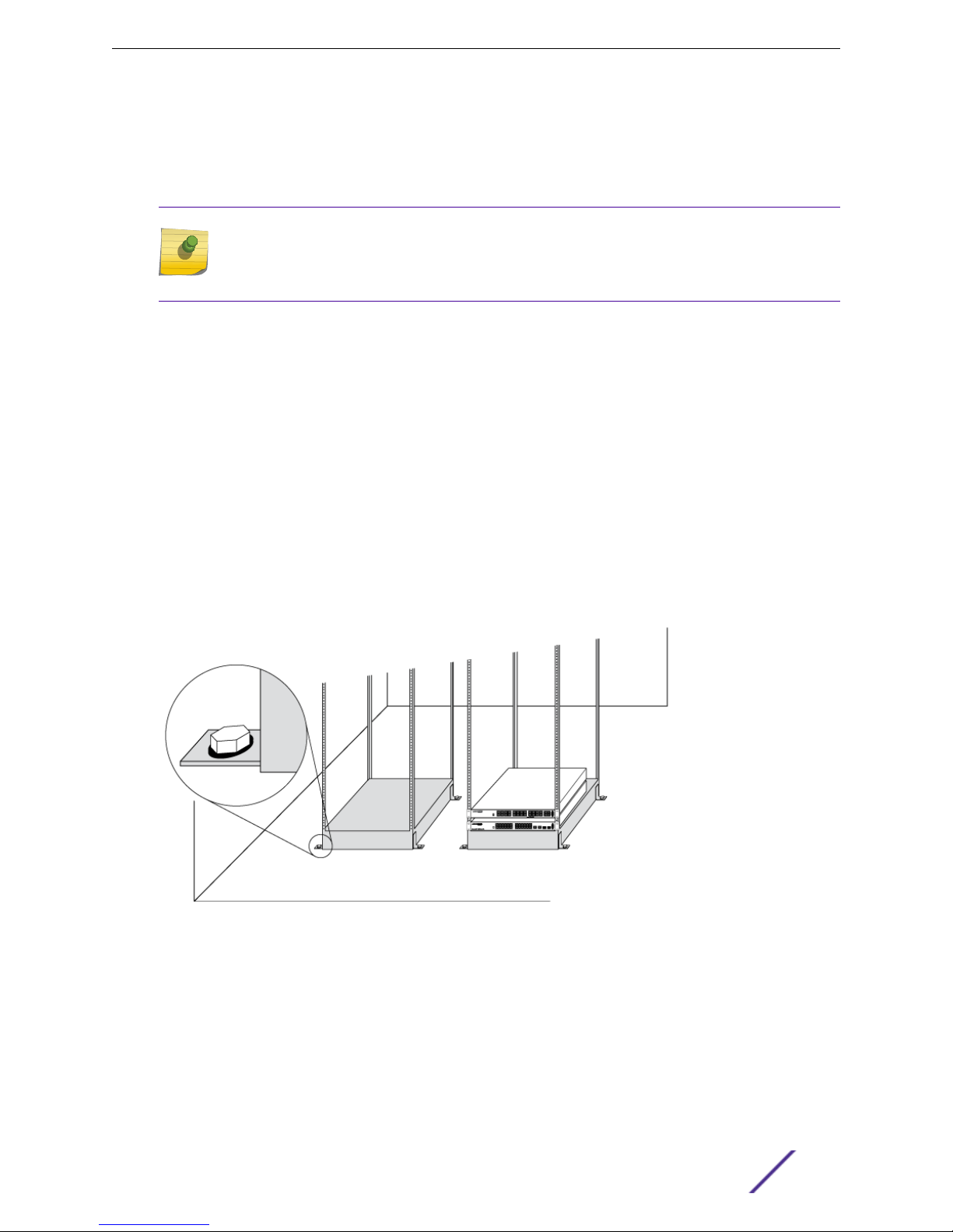
Securing the Rack
Site Preparation
The rack should be attached to the wiring closet floor with 3/8-inch (9.5 mm) lag screws or equivalent
hardware.
The floor under the rack should be level within 3/16-inch (5 mm). Use a floor-leveling cement compound
if necessary or bolt the racks to the floor as shown.
Figure 11: Properly Secured Rack
Brace open equipment racks if the channel thickness is less than 1/4 inch (6.4 mm).
Outdoor Installation
The E4G-200 router can be installed in locations outside of buildings.
E4G Routers Hardware Installation Guide 28

Site Preparation
Prevent unauthorized access to equipment locations and make sure that only qualified service
•
personnel have access to the equipment.
Take reasonable precautions to prevent animals from gaining access to the equipment.
•
Be sure that the ventilation in the installation site is adequate to maintain a temperature below 65°C
•
(149°F) for the E4G-200 router.
For proper airflow through the router, leave clear space on the left and right sides of the router.
•
Evaluating and Meeting Cable Requirements
Use professional consultants for site planning and cabling.
Extreme Networks recommends using the Building Industry Consulting Service International (BICSI)
Registered Communications Distribution Designer (RCDD), which is globally recognized as a standard in
site planning and cabling.
For information, visit www.bicsi.org.
Cable Labeling and Record Keeping
A reliable cable labeling system is essential when planning and installing a network.
Maintaining accurate records helps you to:
Relocate devices easily.
•
Make changes quickly.
•
Isolate faults in the distribution system.
•
Locate the opposite end of any cable.
•
Know the types of network devices that your cabling infrastructure can support.
•
Follow these guidelines when setting up a cable labeling system suitable for your installation:
Identify cables by securely attaching labels to all cable ends.
•
Assign a unique block of sequential numbers to the group of cables that run between each pair of
•
wiring closets.
Assign a unique identification number to each equipment rack.
•
Identify all wiring closets by labeling the front panel of your Extreme Networks equipment and other
•
hardware.
Keep accurate and current cable identification records.
•
Post records near each equipment rack. For each cable drop, include information about the cable
•
source, destination, and jumper location.
Installing Cable
When you connect cable to your network equipment, keep the following things in mind.
Examine cable for cuts, bends, and nicks.
•
Support cable using a cable manager that is mounted above connectors to avoid unnecessary
•
weight on the cable bundles.
E4G Routers Hardware Installation Guide 29
Site Preparation
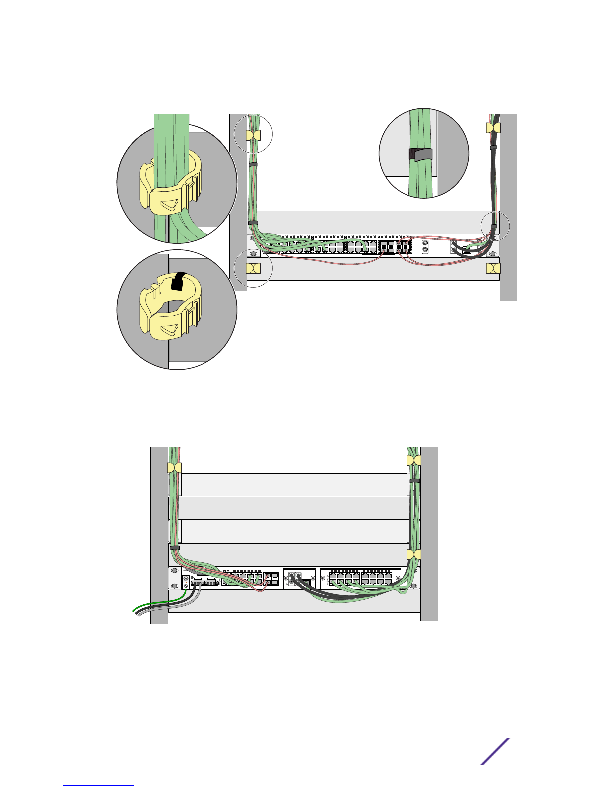
Use cable managers to route cable bundles to the left and right of the network equipment to
•
maximize accessibility to the connectors, as shown in the following figure.
Figure 12: Properly Installed and Bundled Cable for an E4G-400 Router
Provide enough slack, approximately 2 to 3 inches (5 to 8 cm), to provide proper strain relief as
•
shown in the following figure.
Figure 13: Properly Installed Cables, Showing Slack for Proper Strain Relief
Bundle cable using hook-and-loop straps to avoid injuring cables.
•
If you build your own cable, be sure that connectors are properly crimped.
•
When installing a patch panel using twisted pair wiring, untwist no more than 1 inch (2.54 cm) of the
•
cable to avoid radio frequency (RF) interference.
E4G Routers Hardware Installation Guide 30
 Loading...