

Extreme Line ZE600BK.300, ZE600WT.300, ZE1800BK300, ZE2400BK.300, ZE2400WT.300 Original Assembly And Manual Instruction
...
E TREME
X
INE
DE
Stand 07/2014
ORIGINAL MONTAGEUND GEBRAUCHSANLEITUNG
Elektrischer Strahlungsheizer
für den überdachten Außenbereich
Deutsche Version
In Deutschland Konstruiert und Hergestellt
Stand 07/2014
E TREME
X
INE
- 2 -
Inhaltsübersicht
1. Verwendung Seite 3
2. Sicherheitshinweise Seite 4-5
3. Auspacken/Verpackung Seite 5
4. Montageanweisungen Seite 6-14
5. Betrieb Seite 15
6. Montageanweisungen & Mindestabstände Seite 15-17
7. Abmessungen Seite 18
8. Reinigung/Wartung Seite 19
9. Fehlerzustandserkennung Seite 19
10. Technische Daten Seite 20
11. Konformitätserklärung Seite 21
12. Garantie & Gewährleistung Seite 21
13. Ersatzteile Seite 22
14. Außerbetriebnahme/Entsorgung Seite 23
Hersteller: S.E. System Electronic GmbH
Eberloh 5
83128 Halng Germany
Diese Montage - und Bedienungsanleitung umfasst folgende Produkte:
300E-600BK 300E-1800BK 300E-2400BK 300E-3200BK
300E-600WT 300E-1800WT 300E-2400WT 300E-3200WT
Montagehalter MH WH45 DAHV 50 / 30 DAH 30 / 50
ASK DAHDOP DAHDB
Bitte beachten Sie auch die Bedienungsanleitungen zu optional erhältlichem Zubehör (siehe 4.5).

E TREME
X
INE
DE
Stand 07/2014
- 3 -
1. Verwendung
Vielen Dank, dass Sie sich für den Kauf des HEAT ZONE entschieden haben.
Sie haben damit eines der fortschrittlichsten Heizsysteme für den Innen- oder den überdachten
Außenbereich erworben. Der sogenannte Dunkelheizstrahler auf Infrarotbasis zeichnet sich
durch eine fokussierte Wärmeverteilung aus, die die Wärme dorthin transportiert, wo sie benötigt wird. Es wird keine Energie für ungenutzte Flächen verschwendet, wenn der Strahler richtig
montiert ist. Hierzu soll Ihnen die folgende Anleitung dienen.
Der neue Heizstrahler mit seiner Keramikoberäche ist ein hochintensiver Strahlungsheizer, der
im privaten oder gewerblichen Umfeld für den Innen- oder den überdachten Außenbereich
konzipiert wurde und nicht für andere Zwecke genutzt werden darf. Er dient dazu, auf Terrassen,
in Pavillons, Raucherzonen, Wintergärten oder Wellnessbereichen an kühleren Tagen eine angenehme Körperwärme zu erzeugen, ohne in hohem Maße das gesamte Umfeld zu erwärmen. Der
Strahlungsheizer ermöglicht es, die Strahlungswärme bis zu einer Entfernung von etwa 3 Metern
zu transportieren. Das Gerät lässt sich mittels verschiedener Halterungen zielgerichtet auf eine
bestimmte Fläche ausrichten.
1. Vor der Installation lesen Sie bitte die Bedienungsanleitung sorgfältig durch. Diese Bedie-
nungsanleitung ist als Teil des Produktes zu betrachten. Installieren Sie das Gerät erst, wenn Sie
die Bedienungsanleitung gelesen und verstanden haben. Bei Unklarheiten kontaktieren Sie den
Verkäufer oder Hersteller.
2. Bewahren Sie die Anleitung während des gesamten Lebenszyklus des Produktes auf, um
später darin nachschlagen zu können. Geben Sie die Bedienungsanleitung auch an die Nachfolgebesitzer des Gerätes weiter. Stellen Sie sicher, dass gegebenenfalls erhaltene Ergänzungen in
die Bedienungsanleitung eingefügt werden.
3. Bevor Sie mit der Montage beginnen, müssen Sie sich versichern, dass die Betriebsspan-
nung derjenigen entspricht, die auf dem Typenschild des Heizstrahlers oder dem der Zubehörteile angegeben ist.
4. Diese Bedienungsanleitung ist ausschließlich für die oben angegebenen Serienprodukte
bestimmt. Bei Sonderversionen sind Abweichungen bezüglich der technischen Daten, der Montage oder der Abmessungen möglich.

E TREME
X
INE
- 4 -
2. Sicherheitshinweise
Die ortsüblichen Bau- und Brandschutz-Vorschriften sind unbedingt einzuhalten.
WARNUNG: Dieses Gerät ist nicht mit einer Einrichtung zur Regelung der Raumtemperatur
ausgerüstet. Das Heizgerät darf nicht in kleinen Räumen benutzt werden, deren Bewohner diese
nicht selbstständig verlassen können, es sei denn, eine ständige Überwachung der Räume ist
gewährleistet.
1. Der Heizstrahler muss mit einem allpoligen „EIN/AUS“-Schalter ausgestattet werden (nicht
im Lieferumfang enthalten). Man kann den Heizstrahler ebenfalls mittels eines Funkempfängers und einer Funksteuerung (FBM) bedienen, welche optional als Zubehör erhältlich sind.
Der Anschluss an einen Fehlerstromschutzschalter ist notwendig (wird ebenfalls nicht von uns
geliefert).
2. Das Gerät ist mit einem reversiblen Überhitzungsschutz ausgestattet. Wird der Überhit-
zungsschutz ausgelöst, so schaltet er nach einer gewissen Abkühlzeit das Gerät automatisch
wieder ein.
3. Das Gerät darf grundsätzlich nur mit einer zugelassenen Trennvorrichtung betrieben wer-
den. Der Strahler ist standardmäßig mit einem separaten oenen Kabel ohne Stecker für den
elektrischen Anschluss ausgestattet. Ein Anschlusskabel mit Schutzkontaktstecker (Schuko) ist
separat als Zubehör erhältlich.
4. Das Gerät muss fest montiert und von einer Elektrofachkraft an die Hauptstromversorgung
nach den gültigen Standards und Regeln für Elektroverkabelungen des Elektrohandwerks im
jeweiligen Installationsland angeschlossen werden.
5. Der Strahler darf nicht direkt unterhalb einer Steckdose angebracht werden. Von den
Längsseiten sollte ein Sicherheitsabstand von mindestens 10 cm zur nächsten Stromquelle
gewährleistet sein.
6. Nach VDE 0100, Teil 701 darf der Heizstrahler nur im Bereich 3 in Installationsräumen mit ho-
her Feuchtigkeit (Bad, Spa, Pool etc.) montiert werden. Wenn der Heizstrahler in einem solchen
Umfeld mit hoher Feuchtigkeit montiert wird, müssen die Schalter oder die anderen Bediengeräte so angebracht werden, dass sie nicht von Personen, die sich im direkten Kontakt mit Wasser
benden, berührt werden können.
7. Sobald das Gerät mit einer Stromquelle verbunden oder durch einen „ON/OFF“-Schalter
oder eine andere Bedienungsmöglichkeit angeschaltet wurde, dauert es ca. 10 Minuten, bis der
Heizstrahler die optimale Betriebstemperatur erreicht hat.
8. Die Frontseite des Heizstrahlers kann unter Idealbedingungen je nach Raumsituation und
Umgebungseinüssen eine Temperatur von bis zu 360°C erreichen. Berühren Sie keinen Teil des
Heizgeräts während des Betriebs bzw. bis 60 Minuten nach Ausschalten!

E TREME
X
INE
DE
Stand 07/2014
- 5 -
9. Seien Sie vorsichtig bei der Bedienung des Geräts. Dieses Gerät soll nicht von Kindern, von
Personen mit eingeschränkten physischen, sensorischen oder geistigen Fähigkeiten oder von
Personen mit mangelnder Erfahrung und/oder mangelndem Wissen benutzt werden,
es sei denn, sie werden durch eine für ihre Sicherheit zuständige Person beaufsichtigt oder
haben von ihr Anweisungen erhalten, wie das Gerät zu bedienen/benutzen ist.
10. Achten Sie darauf, dass weder Kabel noch Möbel, brennbare Materialien oder andere
Gegenstände mit der Oberäche des Strahlungsheizers in Kontakt kommen und decken Sie
das Gerät niemals ab. Das Gerät darf unter keinen Umständen mit Isolierstoen oder ähnlichen
Materialien abgedeckt werden.
11. Das Gerät darf nie unbeaufsichtigt betrieben werden. Kinder, die sich in der Nähe des
Geräts benden, sollten stets beaufsichtigt werden, um sicherzustellen, dass sie nicht mit dem
Gerät spielen.
12. Wenn die Netzanschlussleitung dieses Gerätes beschädigt wird, muss sie durch den Her-
steller oder seinen Kundendienst ersetzt werden, um Gefährdungen zu vermeiden.
13. Wenn das Gerät oder Zubehörteile einen Defekt, Risse, Bruchstellen oder andere Beschä-
digungen aufweisen, darf das Gerät nicht mehr betrieben werden und muss zur Reparatur von
der elektrischen Leitung/Energieversorgung fachgerecht abgeklemmt, an den Hersteller zurückgeschickt oder entsorgt werden. Das Gerät ist gegen erneutes Wiederanschließen entsprechend
zu kennzeichnen.
14. Beachten Sie, dass sich je nach der derzeit vorhandenen Netzspannung die tatsächliche
sowie aufgrund von Umgebungseinüssen auch die abgegebene Leistung des Gerätes ändert.
15. Achten Sie unbedingt darauf, das Gerät nach dem Benutzen stets wieder auszuschalten.
3. Auspacken/Verpackung
Packen Sie das Gerät und die Zubehörteile vorsichtig aus, verwenden Sie keine spitzen Gegenstände, die das Gerät beschädigen könnten, um die Verpackung zu önen.
Dieses Produkt wurde umweltschonend verpackt. Alle direkt oder über den Handel in Verkehr
gebrachten Heizstrahler-Verpackungen sind nach §6 der Verpackungsverordnung zertiziert.
Somit können alle Heizstrahler-Verpackungen umweltgerecht im Sammelbehälter für Verpackungsmaterialien entsorgt werden. Dabei sind die jeweiligen örtlichen Vorschriften zu beachten. Nähere Informationen erhalten Sie gerne auf Anfrage.
E TREME
X
INE
- 6 -
4. Montageanweisungen
In den Abbildungen auf den folgenden Seiten werden die unterschiedlichen Montagemöglichkeiten des Heizstrahlers gezeigt.
Achten Sie darauf, dass der Heizstrahler sicher und fest mit der Montageoberäche verbunden
ist. Die montierten Befestigungselemente müssen eine Zug- und Scherfestigkeit von mindestens dem dreifachen Gewicht des zu montierenden Heizstrahlers inklusive der Zubehörteile
aufweisen. Verwenden Sie zur Befestigung die entsprechend notwendigen Schrauben und
Dübel (nicht im Lieferumfang enthalten).
Der Heizstrahler darf auf keinen Fall und unter keinen Umständen senkrecht montiert werden.
Die folgende Auistung stellt einen Auszug aus den serienmäßig lieferbaren Zubehör- und Anbauteilen dar. Da auch Sonderversionen verfügbar sind, ist in diesen Fällen bei Bedarf eine entsprechende Montage- und Bedienungsanleitung beim Verkäufer oder Hersteller anzufordern.
Zur Vereinfachung ist in der Montagebeschreibung immer nur eine Montagehalterung dargestellt. Bitte beachten Sie, dass Sie stets zwei Montagehalterungen benötigen, um Ihr Gerät sicher
zu befestigen. Achten Sie immer darauf, dass beide Montagehalterungen exakt in Reihe hintereinander montiert und dabei die Sicherungsclips auf jeden Fall entgegengesetzt ausgerichtet
werden und nach außen zeigen müssen. Beachten Sie hierzu die Mindestmontagemaße des
Gerätes (Maß E) unter Punkt 7 Abmessungen.
Weitere Informationen und Montagemöglichkeiten nden Sie auch auf www.extremeline.de
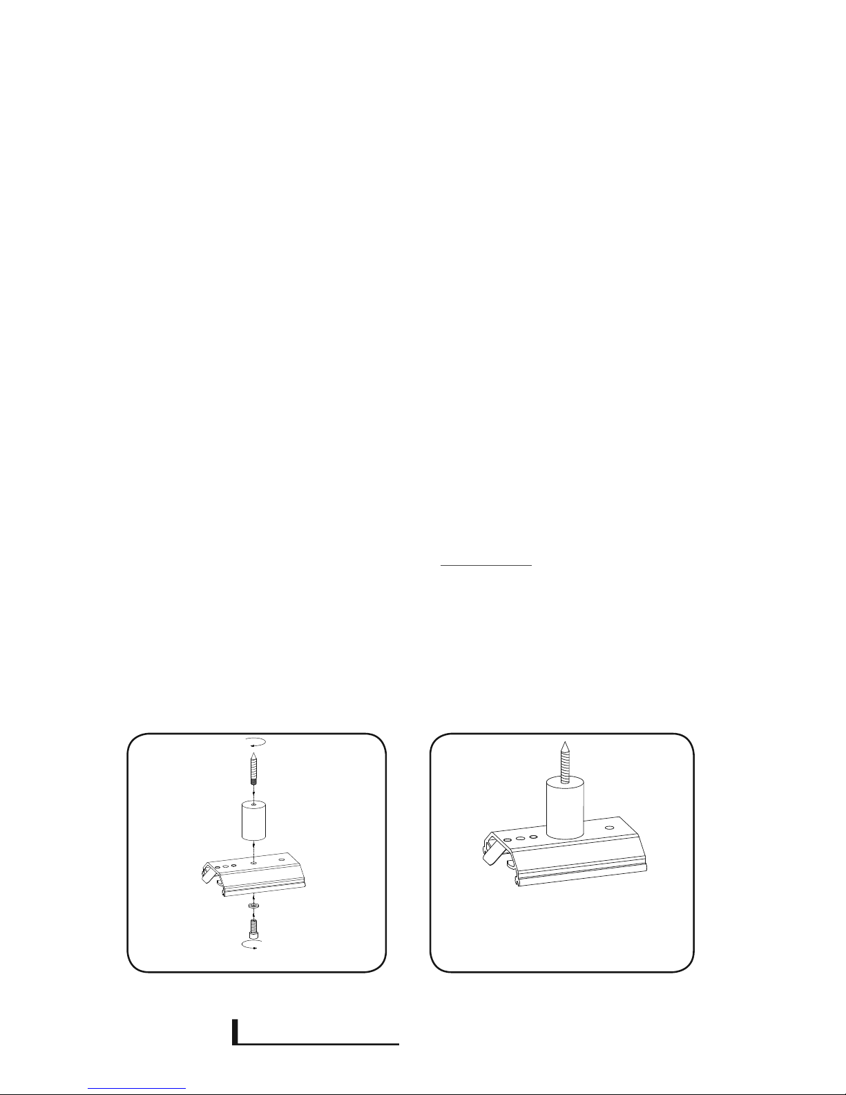
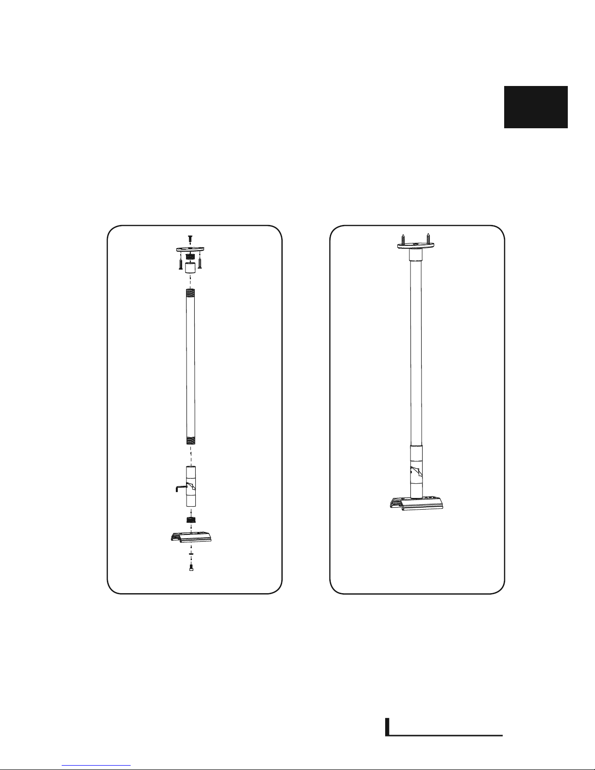
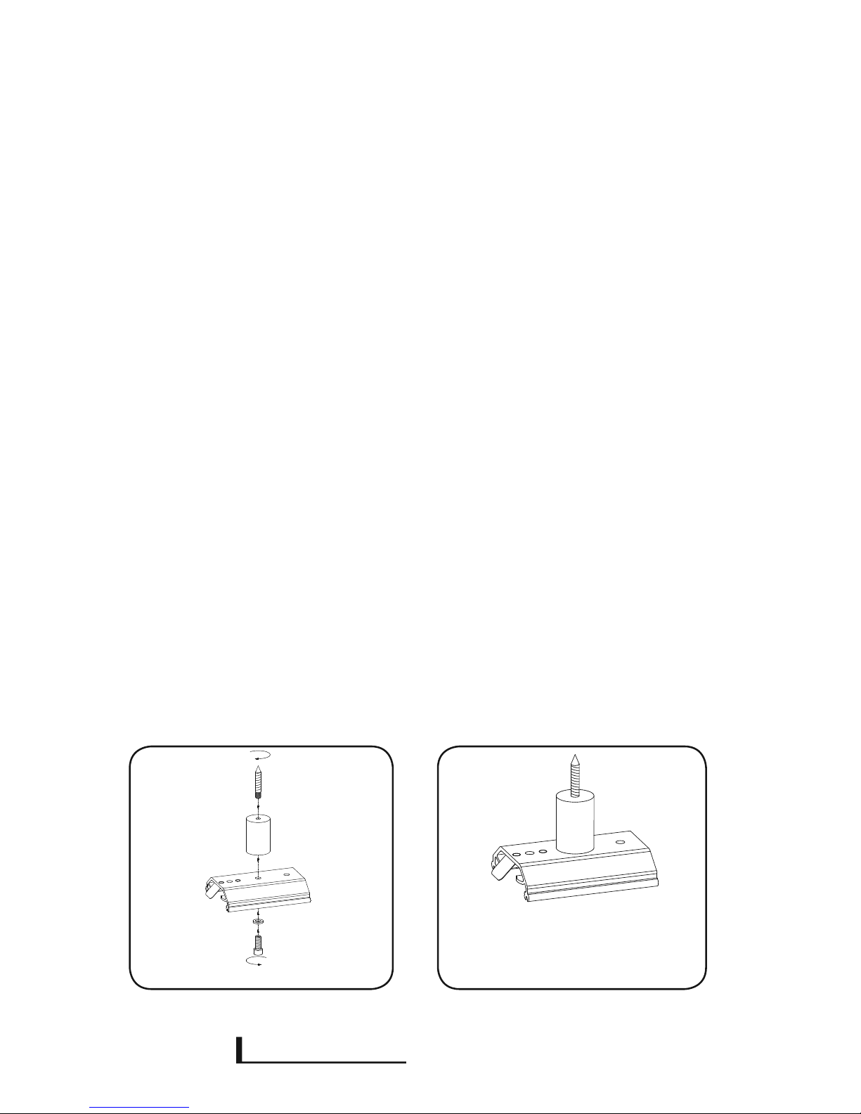
4.1 HEIZSTRAHLER – Montagemöglichkeit 1
Das linke Bild zeigt den Montagehalter MH in der Montagereihenfolge. Das rechte Bild zeigt den
montierten Montagehalter MH.
Montagereihenfolge beachten
2x
Stückliste
2 x Montagehalter MH
2 x Distanzstück DAHS4
2 x Stockschrauben
2 x Beilagscheibe M6
2 x Imbusschraube M6
E TREME
X
INE
DE
Stand 07/2014
- 7 -
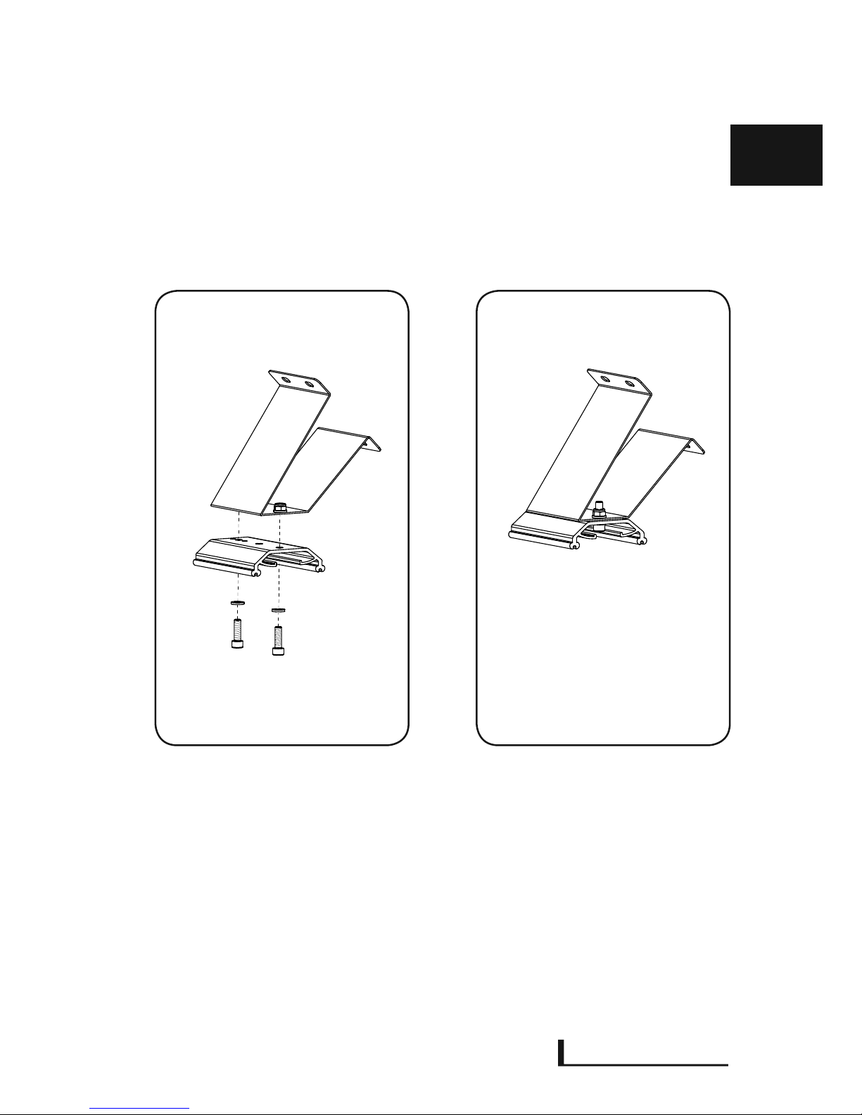
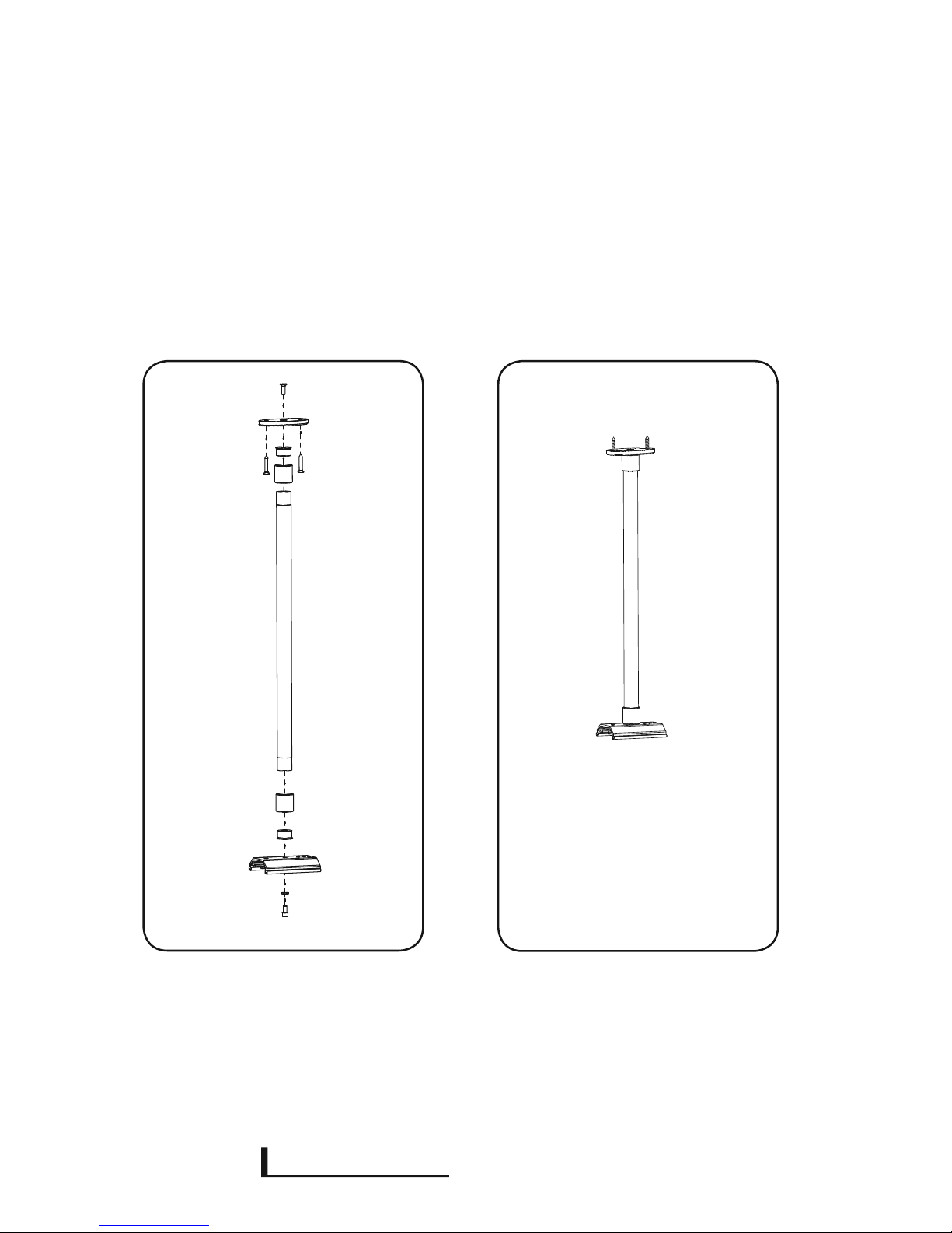
4.2 HEIZSTRAHLER – Montagemöglichkeit 2
Das linke Bild zeigt den Montagehalter MH mit WH45 in der Montagereihenfolge. Das rechte Bild
zeigt den montierten Montagehalter MH mit WH45.
Montagereihenfolge beachten
Stückliste
2 x Montagehalter
4 x Schrauben M6
2x Unterlegscheiben M6
4 x Muttern M6
2x
E TREME
X
INE
2x
- 8 -
4.3 HEIZSTRAHLER – Montagemöglichkeit 3
Das linke Bild zeigt den Montagehalter MH mit GMS und DB in der Montagereihenfolge. Das
rechte Bild zeigt den montierten Montagehalter MH. Stellen Sie den Winkel mit Hilfe eines
Imbusschlüssels ein und ziehen Sie die Imbusschraube wieder fest. Richten Sie die Haltevorrichtung entsprechend Ihrem Heizstrahler aus.
Stückliste
2x Montagehalter
2x Gelenk DAHGMSH
4x Gewindeelement
2x Imbusschrauben M6
2x Unterlegscheiben M6
2x Senkschrauben M6
Montagereihenfolge beachten
E TREME
X
INE
DE
Stand 07/2014
2x
- 9 -
4.4 HEIZSTRAHLER – Montagemöglichkeit 4
Das linke Bild zeigt den Montagehalter MH mit GMS und DAH 30/50 in der Montagereihenfolge.
Das rechte Bild zeigt den montierten Montagehalter MH. Stellen Sie den Winkel mit Hilfe eines
Imbusschlüssels ein und ziehen Sie die Imbusschraube wieder fest. Richten Sie die Haltevorrichtung entsprechend Ihrem Heizstrahler aus.
Stückliste
2 x Montagehalter MH
4 x Gewindeelement
2 x Gelenk DAHGMSH
2 x Befestigung DB
2 x Beilagscheibe M6
2 x Senkschraube M6
2 x Imbusschraube M6
Montagereihenfolge beachten
E TREME
X
INE
2x
- 10 -
4.5 HEIZSTRAHLER – Montagemöglichkeit 5
Das linke Bild zeigt den Montagehalter MH mit DAH30/50 und Befestignung DAHDB in der Montagereihenfolge. Das rechte Bild zeigt den montierten Montagehalter. Richten Sie die Haltevorrichtung entsprechend Ihrem Heizstrahler aus.
Stückliste
2x Montagehalter MH
4x Gewindeelement
2x DAH30 / 50
4x DAH3
2x Befestigung DAHDB
2x Beilagscheibe M6
2x Senkschraube M6
2x Imbusschraube M6
Montagereihenfolge beachten

E TREME
X
INE
DE
Stand 07/2014
- 11 -
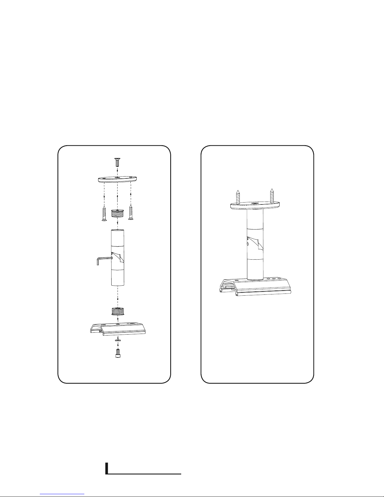
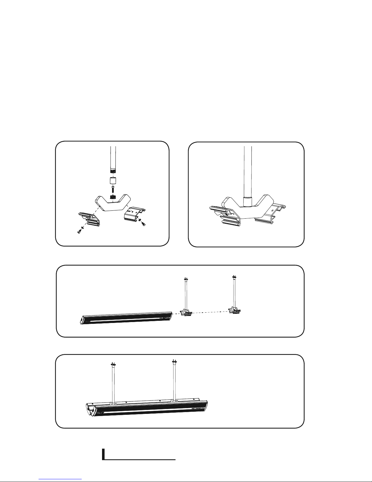
4.6 HEIZSTRAHLER – Montagemöglichkeit 6
Die Bild zeigt eine verstellbare Seileinrichtung zum abhängen des Heizstrahlers in der Montagereihenfolge. Die Seilabhängung kann mittels DAHDB oder DAHS4 montiert werden. Die
Heizstrahler können maximal um 1,5m abgehängt werden. Das Seilsystem ist durch einen
mechanismus individuell verstellbar.
Stückliste
2 Paar Seilsystem
Montagereihenfolge beachten
4x
4x

E TREME
X
INE
- 12 -
4.7 HEIZSTRAHLER – Montagemöglichkeit 7
Das Bild 1 zeigt den DAHDOP mit Montagehalter MH und Gewindeelement zum Abhängen
des Heizstrahlers in der Montagereihenfolge. Die Doppelabhängung kann mittels DAHDB oder
DAH30/50 montiert werden. Beachten Sie hierzu den Punkt 4.5. Das Bild 2 zeigt den
montierten Montagehalter mit DAHDOP, DAH30/50 und DB.
Stückliste
4 x Montagehalter MH
4 x Gewindeelement
4 x DAH3
4 x Beilagscheibe M6
2 x Senkschraube M6
4 x Imbusschraube M6
3.
1. 2.
4.
Montagereihenfolge beachten
2x
E TREME
X
INE
DE
Stand 07/2014
- 13 -
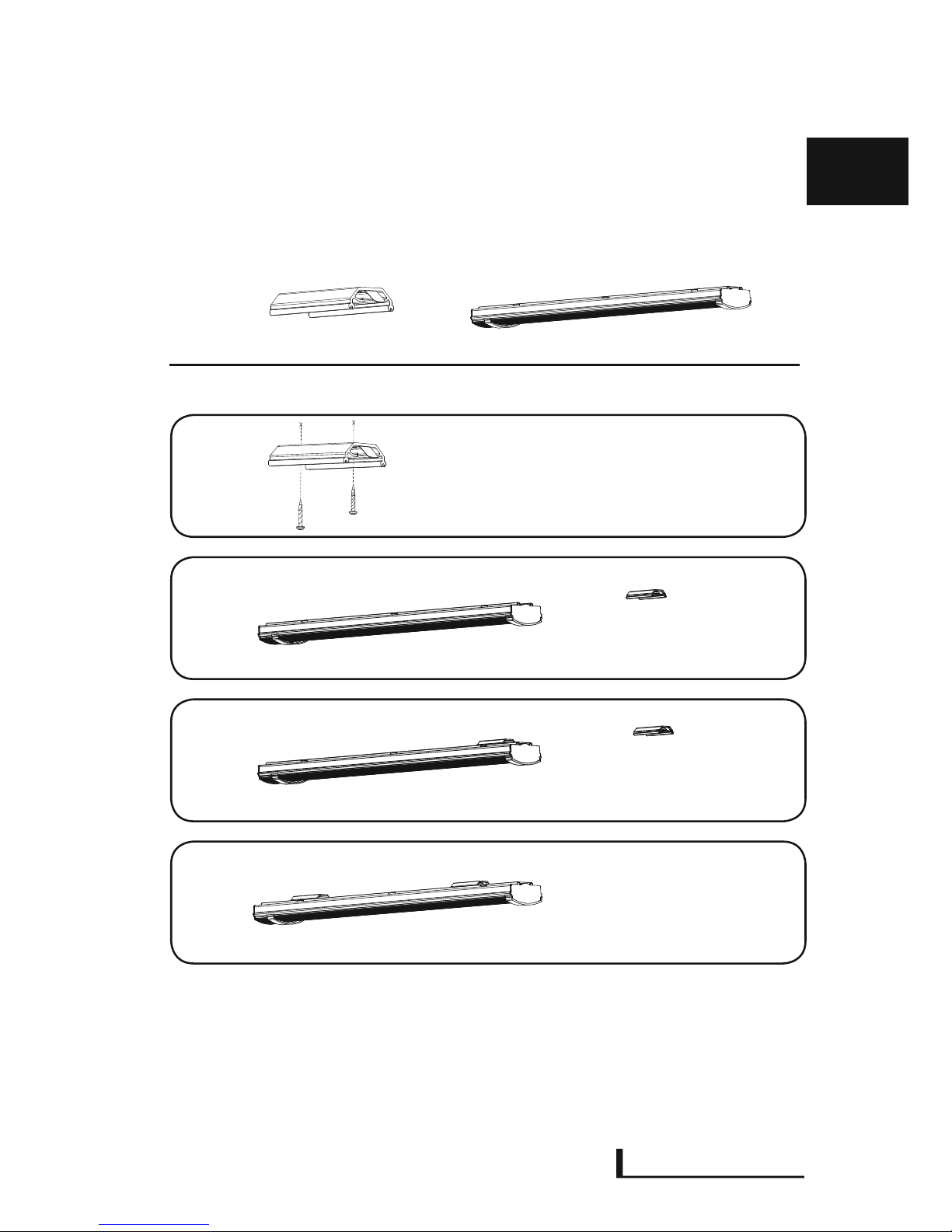
4.8 HEIZSTRAHLER – Grundsätzliche Montage
Befestigungsmaterialien wie Schrauben für die Deckenmontage
sind nicht im Lieferumfang enthalten.
2x 1x
1.
2.
3.
4.
Stückliste
2x Montagehalter
4x Scheibe M6
2x Stockschrauben
E TREME
X
INE
- 14 -
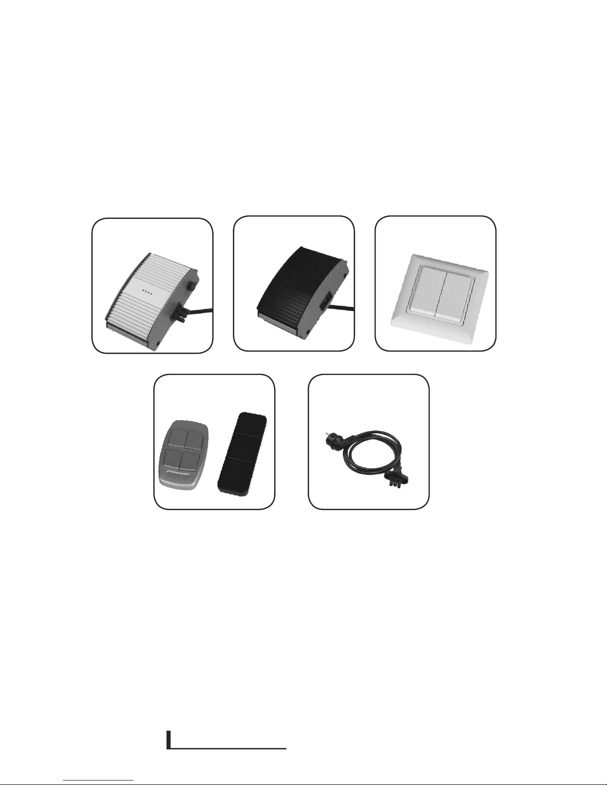
4.9 HEIZSTRAHLER – Einbaugeräte und Zubehör
(optional erhältlich)
Bitte beachten Sie hierzu die separat erhältlichen Bedienungsanleitungen.
Weitere Zubehörteile nden Sie auf www.extremeline.de
* Der Heizstrahler wird regulär mit oenem Kabel ohne Stecker ausgeliefert. Der Anschluss und die entsprechenden notwendigen Prüfungen für ortsfeste Geräte müssen zwingend von einer Elektrofachkraft durchgeführt und dokumentiert werden.
Beachten Sie hier auf jeden Fall die jeweils gültigen Normen, z.B. VDE etc.
Als Zubehör ist das Anschlusskabel ASK mit Schukostecker und Anschlusssteckverbinder,
schwarz mit Rastnase, (16 A/250 V AC 3 x 1,5 mm², Länge ca. 150 cm) erhältlich – ausschließlich
für den europäischen Markt verwendbar.
Funkempfänger Modul
FBM
Anschlusselement
ESM
Wandfernbedienung
FBWS
Handfernbedienung
FBHS
Anschlusskabel
ASK*
E TREME
X
INE
DE
Stand 07/2014
- 15 -
5. Betrieb
Nach erfolgreicher Installation/Montage können Sie das Gerät in Betrieb nehmen.
Der Heizstrahler besitzt eine LED, die in der Abdeckung des Anschlusssteckers integriert ist.
Sobald der Heizstrahler mit Strom versorgt wird, leuchtet diese LED auf und signalisiert, dass das
Gerät sich im Betriebsmodus bendet.
In Verbindung mit Zubehörteilen kann es vorkommen, dass diese LED nicht aueuchtet, obwohl
das Zubehörteil mit Spannung/Strom versorgt wird. Beachten Sie hier auf jeden Fall jeweils die
den Zubehörteilen beiliegende Bedienungsanleitungen.
Obwohl Spannung am Heizstrahler anliegt, kann es vorkommen, dass die LED ebenfalls nicht
leuchtet, wenn der Übertemperaturschutz automatisch aktiviert wurde(siehe 9 Fehlerzustandserkennung).
Vergessen Sie nicht, Ihren Heizstrahler wieder auszuschalten!
6. Montageanweisungen & Mindestabstände
Die nachfolgende Montageanordnung ermöglicht, dass der Heizstrahler eektiv arbeitet. Sie
weist alle Mindestabstände aus, die unabhängig von der Montageumgebung auf jeden Fall
eingehalten werden müssen.
1. Der Heizstrahler muss mit einem allpoligen „EIN/AUS“-Schalter ausgestattet werden (nicht
im Lieferumfang enthalten).
2. Der Heizstrahler kann je nach Montageanordnung unter optimalen Bedingungen eine
Oberächentemperatur von bis zu 360°C erreichen. Wind, Luftfeuchtigkeit, Umgebungstemperatur sowie die Montageanordnung an sich beeinussen die Oberächentemperatur maßgeblich.
3. Montieren Sie das Gerät möglichst so, dass es vor Wind und Wettereinüssen gut geschützt
ist. Durch Wind kühlt die Geräteoberäche stark ab, was die empfundene Körperwärme maßgeblich beeinusst.
4. Montieren Sie das Gerät ausschließlich in Innen- oder überdachten Außenbereichen.
5. Der Heizstrahler darf auf keinen Fall und unter keinen Umständen senkrecht montiert
werden.

E TREME
X
INE
- 16 -
6. Der Heizstrahler muss einen seitlichen Mindestabstand von 30 cm zu jeder angrenzenden
Wand aufweisen, die Vorderseite muss mindestens 80 cm zu jeder Oberäche und und die
Rückseite muss mindestens 6 cm von der Montageoberäche entfernt sein. Gegebenenfalls sind
hier gemäß der örtlichen Brandschutzvorschriften entsprechende weitere Schutzmaßnahmen
zu treen.
7. Oberhalb des Heizstrahlers darf keine Steckdose angebracht sein, zusätzlich muss der Heiz-
strahler mindestens einen seitlichen Abstand von 10 cm zu jeder Steckdose aufweisen.
8. Alle Leitungen müssen so verlegt werden, dass sie zu keiner Zeit mit dem Heizstrahler in
Berührung kommen können.
9. Empfohlene Einsatztemperatur: Um Ihren Heizstrahler eektiv zu betreiben und im Sinne
der allgemeinen Energieeinsparung, achten Sie darauf, diesen nur bei einer Umgebungstemperatur von 10 °C bis 20 °C einzuschalten.
10. Bitte beachten Sie die nachfolgende Abbildung. Die Graken zeigen die Decken- sowie
die Wand- montage des Heizstrahlers inklusive aller einzuhaltenden Mindestabstände. Die
vorgeschriebene Mindestmontagehöhe des Heizstrahlers beträgt 210 cm.
11. Die montierten Geräte müssen einen Abstand von mindestens 80 cm an der längeren
Seite zueinander haben. Werden die Geräte so montiert, dass die Heizächen zueinander ausgerichtet sind, müssen diese einen Abstand von mindestens 300 cm voneinander haben.
6.1 Mindestabstände
Die angegebenen Maße sind Mindestwerte und können von den örtlichen Bau- und Brandvorschriften abweichen. Letztere sind in jedem Fall zu beachten und einzuhalten.
Die dargestellten Montageächen müssen mindestens der Brandschutzklasse A2 entsprechen.
Bitte beachten Sie: Der Heizstrahler erfüllt bei der Deckenmontage die IP-Schutzklasse 4 (IP-X4),
bei der Wandmontage die IP-Schutzklasse 0 (IP-X0).
B
B
A A

E TREME
X
INE
DE
- 17 -
Stand 07/2014
Abstand Wand zu Heizstrahler
Der Abstand X muss mindestens der Länge der
Abhängung zzgl. 80 cm betragen.
Im Schwenkbereich dürfen sich keine brennbaren
Gegenstände benden.
Der Heizstrahler ist als senkrecht hängendes
System bestimmt und darf nicht mittels anderweitiger Hilfsmittel seine bestimmungsgemäße
Position durch seine Schwerkraft verlassen.
Der Heizstrahler mit dem Seilsystem darf nicht an
beweglichen Teilen montiert werden. Genauso ist
es zu unterbinden, das es zu einem aufschwingen
des Gerätes kommen kann.
A > 30 cm zur Wand
> 80 cm zu weiterem Hs
C > 6 cm F > 20 cm
B > 30 cm zur Wand
> 300 cm zu weiterem Hs
D > 210 cm
6.2 Sonderbedingungen Seilabhängung
F
x
B
D
B
C
C
A
A

E TREME
X
INE
- 18 -
7. Abmessungen
Heizäche
elektr. Anschluss, LED
Rückseite/Montageseite
A HEIZSTRAHLER Länge
B Anbaugeräte Länge
C HEIZSTRAHLER Breite
D HEIZSTRAHLER Höhe
E Mindestabstand der
Montagehalter aus
Punkt 4.1 bis 4.8
T y p e /
Maße
A B C D E
600 623 mm 108 mm 169 mm 61,5 mm 200 mm
1800 1023 mm 108 mm 169 mm 61,5 mm 700 mm
2400 1523 mm 108 mm 169 mm 61,5 mm 1200 mm
3200 2023 mm 108 mm 169 mm 61,5 mm 1700 mm
Alle Maße sind ungefähre Angaben.
A B
E
C
D

E TREME
X
INE
DE
Stand 07/2014
- 19 -
8. Reinigung und Wartung
Es ist wichtig, dass der Heizstrahler, sofern er im überdachten Außenbereich angebracht wurde,
regelmäßig gereinigt wird, um eine möglichst langlebige und eziente Funktionsweise zu
gewährleisten.
Die Aluminiumbauweise des Heizstrahler in Verbindung mit der Keramik- oder der eloxierten
Oberäche schützt den Heizstrahler sogar in Küstennähe.
Um eine optimale Wärmeleistung zu erzielen, muss die Oberächen des Strahlers regelmäßig
mit einem feuchten Tuch gereinigt werden. Hierbei ist es besonders wichtig, dass der Strahler
nicht eingeschaltet ist und mindestens 60 Minuten vor dessen Reinigung ausgeschaltet wurde.
Es besteht sonst erhöhte Verletzungs- und Verbrennungsgefahr!
Gewährleisten Sie bei der Reinigung stets, dass am Heizstrahler, an der Steuerung oder am
Anbaugerät keine Spannung/kein Strom anliegt, die Geräte ausgesteckt und während der Reinigung gegen Wiedereinschalten gesichert sind.
Vorsicht!
Benutzen Sie keinen Hochdruckreiniger oder Ähnliches, um den Heizstrahler zu reinigen. Benutzen Sie darüber hinaus keine scharfen Gegenstände und Reinigungsmittel. Stellen Sie sicher,
dass keine Reinigungsrückstände auf dem Gerät verbleiben.
9. Fehlerzustandserkennung
Fehlerbeschreibung Ursache Behebung
Der Heizstrahler wird nicht heiß. - falsche Spannung
- keine Spannung
- das Gerät ist defekt
- Netzspannung
überprüfen
- evtl. Gerät einschicken
Der Heizstrahler riecht verbrannt. - bei erst Innbetriebnahme
- das Gerät ist Defekt
- Gerät auf Verunreinigungen Prüfen
- evtl. Gerät einschicken
Am Heizstrahler leuchtet die LED
nicht, obwohl er eingeschaltet
ist.
- Übertemperaturschutz hat sich
eingeschaltet
- das Gerät ist defekt
- Gerät ausstecken und abkühlen lassen
- evtl. Gerät einschicken
Der Heizstrahler löst den Fehlerstrom-Schutzschalter oder die
Sicherung aus.
- Gerät wurde nass
- das Gerät ist defekt
- Gerät nicht mehr in
Betrieb nehmen
- evtl. Gerät einschicken
Der Heizstrahler wird nicht warm
genug.
- falsche oder ungünstige Montage anordnung
- Umgebungstemperatur zu niedrig
- Umwelteinüsse, Temperatur,
Wind, Schnee
- zu niedrige Spannung
- Montageanordnung überprüfen

E TREME
X
INE
- 20 -
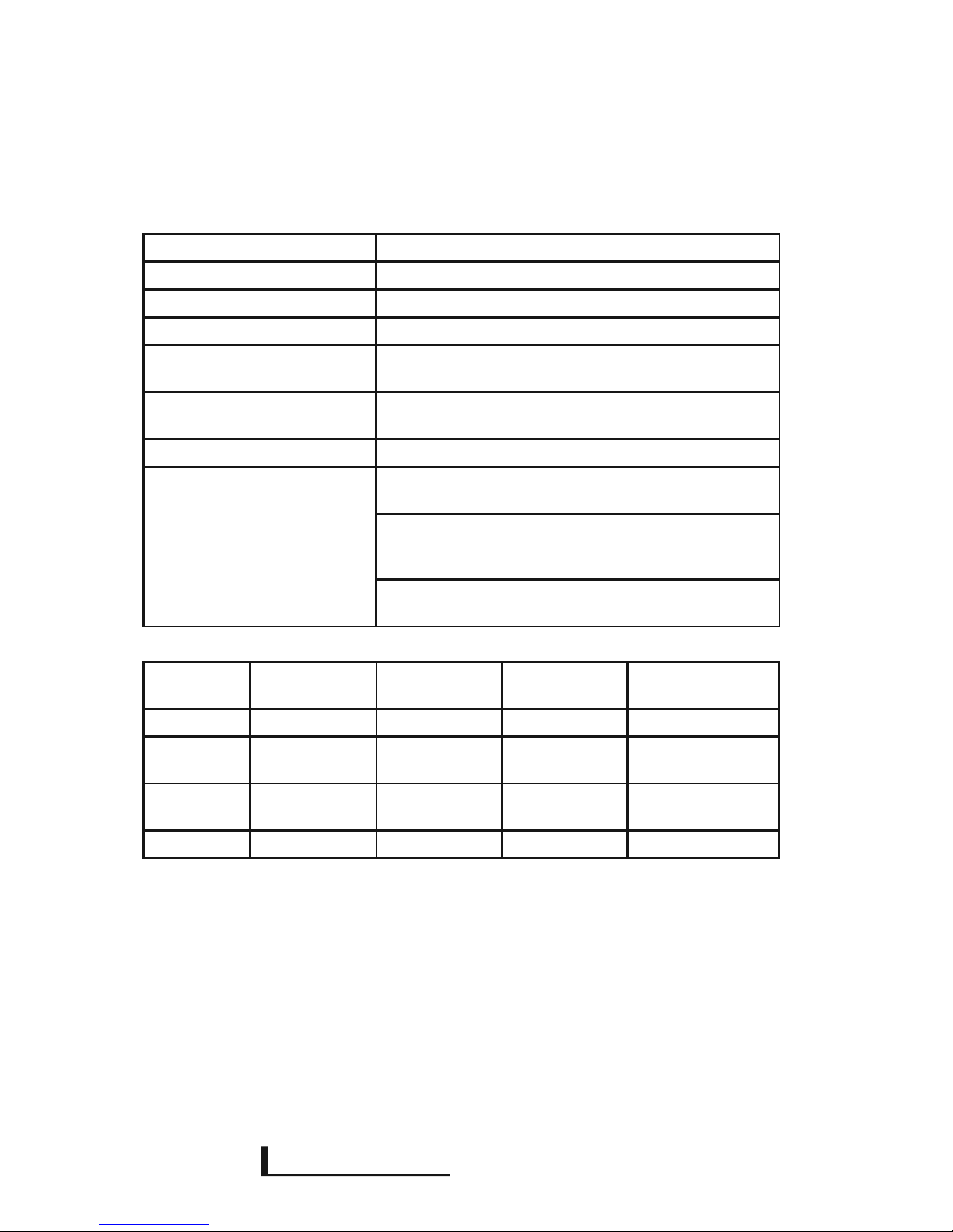
10. Technische Daten
Betriebsspannung 220-240 V / 50 Hz
Temperatur der Heizäche bis zu 360° C
Temperatur des Gehäuses bis zu 110° C
Aufheizzeit ca. 10 min
Schutzklasse bei der Deckenmontage IPX4
bei der Wandmontage IPX0
Betriebsumgebungstemperaturen
-5°C bis +23°C
rF 70% nicht betauend
Lagertemperatur -20 bis +65 °C
Anschluss 3 x 1,5 mm² oenes Plugin-Kabel ohne Stecker, tempera-
turbeständig bis 170° C, 1,5 m Länge
oder 3 x 1,5 mm² Plugin-Kabel mit Schutzkontaktstecker,
temperaturbeständig bis 170° C, 1,5 m Länge (optional als
Zubehör erhältlich)
oder Anbaugeräte
(optional als Zubehör erhältlich)
Type 300E-600BK
300E-600WT
300E-1800BK
300E-1800WT
300E-2400BK
300E-2400WT
300E-3200BK
300E-3200WT
Leistung 600 W 1800 W 2400 W 3200 W
Strombedarf ca. 2,5 A ca. 8 A ca. 11 A ca. 14 A
Maße 61,5 x 169 x
623 mm
61,5 x 169 x
1023 mm
61,5 x 169 x
1523 mm
61,5 x 169 x
2023 mm
Gewicht 3 kg 5 kg 8 kg 11 kg
Bitte beachten Sie auch die Bedienungsanleitungen von Zubehörartikeln zu den Geräten. Die
gültigen Bau-, Emissions- und Brandschutzvorschriften sind stets einzuhalten. Technische Änderungen dienen dem Fortschritt und sind vorbehalten.

E TREME
X
INE
DE
Stand 07/2014
- 21 -
11. Konformitätserklärung
Die Konformitätserklärung erhalten Sie auf Wunsch gerne direkt bei uns. Kontakt siehe Rückseite.
12. Garantie & Gewährleistung
Der Heizstrahler hat eine Garantie von 24 Monaten. Die Garantiezeit beginnt an dem Tag, an
dem das Neu-Gerät erworben wurde. Verschleißartikel oder Mängel, die die Gebrauchstauglichkeit des Gerätes nur unerheblich beeinussen, sind von der Garantie ausgeschlossen. Der
Garantieanspruch muss durch die Originalrechnung, auf der das Kaufdatum und das Gerätemodell ersichtlich sind, nachgewiesen werden.
Abwicklung im Garantiefall
Mit dem gültigen Kaufbeleg senden Sie das defekte Gerät bitte mit einer detaillierten Fehlerbeschreibung an den Hersteller. Bitte haben Sie Verständnis, das nur Reklamationen mit einer
detaillierten Fehlerbeschreibung zügig bearbeitet werden können. Ein Formblatt, um die Fehlerbeschreibung zu vereinfachen, erhalten Sie vom Hersteller. Das eingesendete Gerät wird vom
Hersteller nur mit ausreichender Transportverpackung, die das Gerät während des Transports
entsprechend schützt, angenommen.
Der Hersteller wird nach eigenem Ermessen die Garantieansprüche mittels Reparatur oder
Austausch des fehlerhaften Gerätes oder einzelner Teile des fehlerhaften Gerätes erfüllen. Bei einem Austauschgerät können Form und Farbe geringfügig vom ursprünglich erworbenen Gerät
abweichen. Den Beginn der Garantiezeit bestimmt das ursprüngliche Kaufdatum und verlängert
sich nicht, wenn das Gerät vom Hersteller ausgetauscht oder repariert wurde.

E TREME
X
INE
- 22 -
Garantieausschlüsse
Schäden oder Mängel, die durch unsachgemäße Handhabung oder unsachgemäßen Betrieb
verursacht wurden, sowie Defekte, die durch die Verwendung von Nicht-Originalteilen oder durch
die Verwendung von nicht vom Hersteller empfohlenem Zubehör entstehen, werden nicht von der
Garantie abgedeckt.
Die Garantie deckt keine Schäden ab, die durch äußere Einüsse wie z. B. Brand, Blitzschlag,
Wasser oder jegliche Transportschäden entstanden sind.
Die Haftung für Folgeschäden an Personen oder Sachen sind ausgeschlossen.
Wenn die Seriennummer des Gerätes verändert, entfernt oder unleserlich gemacht wurde, kann
die Garantie nicht in Anspruch genommen werden.
Alle Garantieansprüche erlöschen, wenn das Gerät durch eine vom Hersteller nicht autorisierte
Person geönet, verändert, modiziert, umgebaut oder repariert wurde.
13. Ersatzteile
Kontaktieren Sie bitte den Hersteller, falls Sie Ersatzteile benötigen.

E TREME
X
INE
DE
Stand 07/2014
- 23 -
14. Außerbetriebnahme/Entsorgung
Pegehinweise
Dieses Produkt wurde umweltschonend verpackt. Alle direkt oder über den Handel in Verkehr
gebrachten Heizstrahler-Verpackungen sind nach §6 der Verpackungsverordnung zertiziert.
Somit können alle Heizstrahler-Verpackung umweltgerecht im Sammelbehälter für
Verpackungsmaterialien entsorgt werden. Dabei sind die jeweiligen örtlichen Vorschriften zu
beachten. Nähere Informationen erhalten Sie gerne auf Anfrage.
Nach Ablauf seiner Funktionsfähigkeit ist das Gerät durch einen Fachmann nach den geltenden
Regeln außer Betrieb zu nehmen und gegen Wiederinbetriebnahme zu sichern.
Das Gerät muss fachgerecht und umweltschonend entsorgt werden. Dabei sind die örtlichen
Vorschriften zu beachten.
Pegehinweis
Wichtig! Vor dem ersten Gebrauch die Oberäche mit handelsüblichem Glasreiniger säubern.
Fingerabdrücke können Verfärbungen auf der Oberäche verursachen.
Aufkleber und Hinweise nach internationalen Standards und Vorgaben
UL499 Cl. 45.9: CAUTION!
Do not install heater closer than 3 inches (or 60 mm) to the ceiling.
Do not install heater closer than 12 inches (or 300 mm) to a horizontal surface.
Do not install heater closer than 32 inches (or 800 mm) to a vertical surface.
UL499 Cl. 45.10: CAUTION! To provide continued protection against risk of electric shock, connect to properly grounded outlets only.
UL 499 Cl. 45.35: CAUTION! Hot Surface! Avoid Contact!
Generelle Hinweise nach internationalen Standards und Vorgaben
UL499 Cl. 45.15: CAUTION!
a) Have a qualied electrician install a properly grounded receptacle outlet, acceptable for outdoor use and protected from snow
and rain, immediately adjacent to the location where the heater will be used.
b) Route the supply cord and locate the heater so as to be protected from damage by live stock.
c) Do not use extension cords.
d) Inspect cord before using.
e) Unplug heater at receptacle outlet when not in use or before removing from tank, and store heater indoors after winter
season.
UL499 Cl. 47.16: CAUTION! The radio transmitter is not intended for use by persons
(including children) with reduced physical, sensory or mental capacity – it has to be kept out of
reach from these persons especially from children.
UL499 Cl. 47.16: Heater together with all available accessories features
IP protection class
IPX4 tested following IEC, classied NEMA type 3R.
UL499 Cl. 54.2: CAUTION! To provide continued protection against the risk of
electric shock, disconnect the supply cord before cleaning.

E TREME
X
INE
Bitte beachten Sie:
Alle Angaben in dieser Anleitung entsprechen dem heutigen Stand unserer Kenntnisse und sollen über unsere Produkte und mögliche Anwendungen informieren
(technische Änderungen und Weiterentwicklungen, Irrtümer und Druckfehler
vorbehalten).
S.E. System Electronic GmbH
Eberloh 5
83128 Halng
Germany
Stand: März 2014
Produktion und Vertrieb elektronischer
Baugruppen und Systeme
Hersteller:

E TREME
X
INE
EN
Stand 07/2014
ORIGINAL ASSEMBLY
AND MANUAL INSTRUCTION
Electrical radiant heater
for roofed outdoor area
English Version
Exclusively engineered and made in Germany.

E TREME
X
INE
- 26 -- 26 -
Index
1. Utilization side 27
2. Safety Instructions side 28-29
3. Unpacking / Package side 29
4. Assembly Instructions side 30-38
5. Operation side 39
6. Assembly Instructions & Minimum Distances side 39-41
7. Dimensions side 42
8. Cleansing / Maintenance side 43
9. Error Detection side 43
10. Technical Data side 44
11. Declaration of conformity side 45
12. Guarantee side 45-46
13 Spare Parts side 46
14. Decommissioning / Disposal side 47
Manufacturer:
S.E. System Electronic GmbH
Eberloh 5
83128 Halng Germany
This assembly and manual instruction comprises the following products:
300E-600BK 300E-1800BK 300E-2400BK 300E-3200BK
300E-600WT 300E-1800WT 300E-2400WT 300E-3200WT
Assembly holder MH WH45 DAHV 50 / 30 DAH 30 / 50
ASK DAHDOP DAHDB
Please pay attention to the manual instructions of the optionally available accessories (see 4.5).
E TREME
X
INE
- 27 -
EN
Stand 07/2014
1. Utilization
Many thanks that you have decided to purchase our electrical radiant heating.
By doing so, you have received one of the most progressive heating systems for the roofed
indoor and outdoor area.
The so-called. Dark radiant heater, which is based on infrared, is characterized by a purposeful distribution of heat energy and by transporting the heat exactly to where it is needed. No
energy is wasted for unused space provided that the radiator is mounted properly. The following
instructions provide information on this.
The new radiant heater, with its ceramic surface, is a highly intensive radiant heater, which is
designed for roofed outdoor or indoor areas in a private or commercial environment and is
not meant to be used for other purposes. It serves for producing a comfortable body heat on
terraces, in pavilions, smoking areas, winter gardens or wellness areas, without overheating
the whole area. The radiant heater is able to transport the radiant heat over a distance of up to
approximately 3 meters. The heater can be aligned onto a certain surface due to various mounting brackets.
1. Before mounting please read the manual instruction thoroughly. The manual instruction is
to be considered as a part of this product. Do not assemble the device before having read and
understood the manual instructions. In case of obscurities please contact the seller or manufacturer.
2. Keep the manual for the whole durability of the product in order to be able to consult it at
a later point of time. Hand over the manual to each following proprietors of the device. Please
ensure that you add every piece of information you have additionally received to the manual.
3. Before mounting the heater you have to make sure that the operating voltage is conrm
with the voltage mentioned on the type plate belonging to the radiant heater or the spare parts.
4. This manual instruction is one and only determined for the above-mentioned serial pro-
ducts. In case of special versions, deviations concerning technical data, assembly and dimensions may be possible. Many thanks that you have decided to purchase our electrical radiant
heating.
By doing so, you have received one of the most progressive heating systems for the roofed
indoor and outdoor area.
The so-called. Dark radiant heater, which is based on infrared, is characterized by a purposeful distribution of heat energy and by transporting the heat exactly to where it is needed. No
energy is wasted for unused space provided that the radiator is mounted properly. The following
instructions provide information on this.

E TREME
X
INE
- 28 -
2. Safety Instructions
Keep to the local building and re protection regulations.
WARNING: This unit is not equipped with a device to control the room temperature. The heater
must not be used in small spaces, inhabited by people who are themselves constantly can not
leave the room unless constant supervision is ensured.
1. The heater should be equipped with an all-pole on/o switch (not included in scope of deli-
very) The radiant heater can also be controlled by means of a radio receiver and a remote control
which are optionally available as accessories. It must necessarily be connected to a residual
current circuit breaker.
2. The device is equipped with a reversible overheating protection. If the overheating protecti-
on gets triggered, it automatically switches on the device after a certain time of cooling o.
3. The device may generally only be operated with an approved separator. The radiator is
always equipped with a separate open cable without a plug for electrical connection. A connection cable with a protective contact plug (Schuko) is separately available as accessory.
4. The device must be connected rmly and by an electrician to the main current supply line
as per the currently valid standards and rules for electronic cabling of the electronics craft in the
respective country.
5. The radiator may not be mounted directly underneath a socket. A distance of at least 10 cm
between the long side and the next current source should be guaranteed.
6. As per VDE 0100 part 701 the radiant heater may only be assembled in area 3 of rooms
with a high humidity (bathroom, spa area, pool,…). If the radiant heater is mounted in such an
humid area the switch or other operator units are to be mounted in a way so that they cannot be
touched by persons who are directly in contact with water.
7. As soon as the device is connected with a current source or has been switched on by means
of a on/o switch or other operation possibilities approximately 10 minutes are needed until the
radiate heater has reached the optimal operation temperature.
8. In case of ideal conditions the front of the radiant heater can reach a temperature of up to
380°C, depending on room conditions and inuences on the environment. Do not touch any
part of the heating device while it is operated and/or 60 minutes after switching it o.

E TREME
X
INE
- 29 -
EN
Stand 07/2014
9. Be careful while operating the device. This device is not meant to be used by persons
(including children) who are physically, sensorially or mentally handicapped, not suciently
experienced or have a lack of knowledge, unless they are supervised by a person who is responsible for safety and protection or have been instructed by such a person concerning how to use
the device.
10. Take care that neither cable nor pieces of furniture, ammable objects or other items get
in contact with the heater`s surface and do never cover the device. The device must never be
covered by insulating material or similar materials.
11. The device may never be operated without being supervised. Children must always be
supervised in order to ensure that they do not play with the device.
12. If the mains connection is damaged it has to be replaced by the manufacturer or his
customer service to avoid danger.
13. In case of the device or accessories showing a failure, rupture, crack or other damages it
may not be operated anymore and must be professionally disconnected from the current line for
repair and returned to the manufacurer or disposed. The device is to be marked accordingly in
order to avoid that it is connected again.
14. Please note that the device`s actual power output as well as that inuenced by certain
conditions in the area changes depending on the current mains voltage.
15. Do urgently mind that the device must always be switched o after utilization.
3. Unpacking/Packaging
Unpack the device and accessories carefully, for unpacking do not use sharp objects, which
could damage the device.
This product has been packed environmentally friendly. All packages for heaters that were
directly or by means of traders brought in circulation are certied according to §6 of the regulations on packaging. For that reason, all packages for heaters can be disposed environmentally
compatible into collecting tanks for packaging materials. We are resting to your disposal for any
further information on this matter.
E TREME
X
INE
- 30 -
4. Assembly Instructions
On the pictures of the following pages (ref. no. 4) you can see all possibilities for mounting the
radiant heater.
Please take care that the radiant heater is securely and rmly connected with the surface it is
supposed to be mounted on. The mounted fastening elements must have a tensil and shear
strength of at least three times as much of the weight of the radiant heater that is to be mounted, including all accessories. For mounting use appropriate screws and dowels (not included in
scope of delivery).
The radiant heater may never be mounted in a vertical position.
The accessories and attachments listed below are part of the available standard range. Since
special versions are also available, please demand the respective assembly and manual instruction from the trader or manufacturer.
By reason of simplication, only one of the mounting brackets is pictured in the assembly
instruction. Please not that always two mounting brackets are required to securely mount the
device. Always take care that both of the mounting brackets are mounted exactly one after another in a row and that the security clips must be aligned contrarily and are adjusted outwardly.
Please consider the mounting minimum of the device (ref. point 7 dimensions).
Further information and mounting possibilities can be found at www.extremeline.de
4.1 RADIANT HEATER - mounting possibility 1
On the left picture you see the mounting bracket MH and the order how to mount it. The picture
on the right side shows the mounted mounting bracket MH.
Keep to the mounting order
List of components:
2x mounting bracket MH
2xspacer DAHS4
2x hanger bolt
2x washer M6
2x allen bolt M6

E TREME
X
INE
- 31 -
EN
Stand 07/2014
4.2 RADIANT HEATER – mounting possibility 2
On the left picture you see the mounting bracket MH together with WH45 and the order how to
mount them. The picture on the right side shows the mounted mounting bracket MH together
with WH45.
List of components
2 x mounting brackets
4 x bolts M6
2x washers M6
4 x nuts M6
Keep to the mounting order

E TREME
X
INE
- 32 -
4.3 RADIANT HEATER – mounting possibility 3
On the left picture you see the mounting bracket MH together with GSL and DB and the order
how to mount them. The picture on the right side shows the mounted mounting bracket MH.
Adjust the angle by means of an allen key and tie up the allen bolt again. Adjust the fastening
according to your radiant heater.
List of components
2x mounting bracket
2x joint GSL
4x thread element
2x allen screws M6
2x washers M6
2x countersunk bolts M6
Keep to the mounting order

E TREME
X
INE
- 33 -
EN
Stand 07/2014
4.4 RADIANT HEATER – mounting possibility 4
On the left picture you see the mounting bracket MH together with GSL and DAH 30/50 and
the order how to mount them. The picture on the right side shows the mounted mounting
bracket MH. Adjust the angle by means of an allen key and tie up the allen bolt again. Adjust the
fastening according to your radiant heater.
List of components
2x mounting bracket MH
4x thread element
2x DAH30 / 50
4x DAH3
2x fastening DB
2x washer M6
2x countersunk bolt M6
2x allen bolt M6
Keep to the mounting order

E TREME
X
INE
- 34 -
4.5 RADIANT HEATER – mounting possibility 5
On the left picture you see the mounting bracket MH together with GSL and DAH and the order
how to mount them. The picture on the right side shows the mounted mounting bracket MH.
Adjust the fastening according to your radiant heater.
List of components
2x mounting bracket MH
4x thread element
2x DAH30 / 50
4x DAH3
2x fastening DB
2x washer M6
2x countersunk bolt M6
2x allen bolt M6
Keep to the mounting order

E TREME
X
INE
- 35 -
EN
Stand 07/2014
4.6 RADIANT HEATER – mounting possibility 6
The picture shows an adjustable cord unit to hang the radiant heater in the right order of
mounting steps. The cord suspension can be mounted by means of DAHDB or DAH3. The radiant
heaters can be hung by 1.5 m at the most. The cord system can be individually adjustet due to a
machanism.
List of components
2 pairs of cord systems
Keep to the mounting order
4x
E TREME
X
INE
- 36 -
4.7 RADIANT HEATER – mounting possibility 7
The left picture shows the DAHDOP together with the mounting bracket MH und the thread
element for hanging the radiant heater according to the order of mounting steps. The double
suspension can be mounted by means of DAHDB or DAH30/50. In connection with this, refer
to point 4.5. On the right picture you can see the mounted mounting bracket with HDOP,
DAH30/50 and DB.
List of components
4x mounting brackets MH
2x thread element
2x DAH3
4x washer M6
2x countersunk bolt M6
4x allen bolt M6
3.
1. 2.
4.
Keep to the mounting order

E TREME
X
INE
- 37 -
EN
Stand 07/2014
4.8 RADIANT HEATER – basic mounting
Fastening materials like bolts for ceiling suspension are not
included in scope of delivery.
2x
1x
1.
2.
3.
4.
List of components
4x mounting brackets MH
2x thread element
2x DAH3
4x washer M6
2x countersunk bolt M6

E TREME
X
INE
- 38 -
4.9 RADIANT HEATER – built-in units and accessories
(optionally available)
Please note that the respective manuals are separately available.
Further accessories can be found at www.extremeline.de
* The radiant heater is by default delivered with an open cable without plug. Connection and any neccessary checks for stationary devices must urgently be performed and documented by an professional electrician.
Please consider in any case the respective validated rules, i.e. VDE.
As an accessory, the connection cable ASK with the Schuko plug is exclusively available for the European market (with silicone
lines and connector plug, black with snap-in hole, 16 A/250 V AC 3 x 1,5 mm2, length appr.. 150 cm)
Radio receiver unit
FBM
Connection element
ESM
remote control for wall
FBWS
mobile remote control
FBHS
Connection cable
ASK*

E TREME
X
INE
- 39 -
EN
Stand 07/2014
5. Operation
After having mounted the device successfully, you can now put it in operation.
The radiant heater includes a LED which is built in the covering plate between teperature prole
and faceplate. As soon as the radiant heater is fed with electricity the LED begins lighting and
signalizes that the devise is in operating mode.
In connection with accessories, the LED may not light up, although the accessory is fed with
voltage/electricity. In that case, do refer to the respective manuals enclosed to the accessories.
Despite the fact that voltage is attached tot he radiant heater, the LED may not light as well, if
the overtemperature protection has been activated.
Do never forget to switch o the radiant heater!
6. Assembly Instructions and Minimum Distances
The following assembly instructions ensure that the radiant heater works eectively. All
minimum distances are mentioned and must urgently be kept to, regardless of the mounting
location.
1. The radiant heater must be provided with an on/o switch (not included in scope of deli-
very, optionally available as accessory, see 4.6).
2. The radiant heater can, depending on the assembly instruction and in case of optimal con-
ditions, reach a surface temperature of up to 380°C. Wind, humidity, ambient temperature and
the assembly instruction itself have a signicant impact on the surface temperature.
3. Make sure that the the mounted device is perfectly protected from inuences of wind
and weather. Wind cools strongly down the device`s surface, whereby the sensed body heat is
inuenced signicantly.
4. Do only mount the device in a roofed indoor or outdoor area.
5. The radiant heater may never be mounted in a vertical position.

E TREME
X
INE
- 40 -
6. A distance of at least 30 cm between the short side of the radiant heater and the contiguous
walls is necessary, the distance beween the front-side and any surface must be 80 cm and at
least 6 cm must be between the heater and the back assembly surface. If necessary, please take
further protective measures as per the local re protections rules.
7. No socket may be situated above the radiant heater and, additionally to that, there must not
be a socket in up to 10 cm next to the heater.
8. Cords must never get in contact with the radiant heater.
9. Recommended operating temperature: In ordert o make sure that your radiant heater is
eectively operated and that energy is saved, do only switch on the heater when the ambient
temperatur is between 10 °C and 20°C.
10. Please see the following picture. The graphics show how to mount the radiant heater on
ceilings as well as on walls, all minimum distances inclusive. The radiant heater must be mounted in a height of at least 210 cm.
11. Please ensure that a space of at least 80 cm is left between the long sides of he mounted
devices. If the devices are mounted in a way that the heating surfaces in front of each other the
distance between them must be at least 300 cm.
6.1 Minimum Distances
The indicated dimensions are calculated as minimum distances and can be dierent to the local
building and re protection regulations. The latter must urgently be kept to.
The pictured mounting surfaces must at least correspond to re protection classication A2.
Please note: If the radiant heater is mounted on the ceiling it is in conformity with the IP protection classication 4 (IP-X4), if it is mounted on a wall it is in conformity with the IP protection
classication 0 (IP-X0).
B
B
A A

E TREME
X
INE
- 41 -
EN
Stand 07/2014
Distance between wall and heater
Distance X must be at least as long as the
length of the suspension, plus 80 cm.
No ammable objects may be placed within
the pivoting range.
The radiant heater is meant to be a vertically
hanging system and its position, xed by force
of gravity, may by no means be changed.
The radiant heater and its cord system may not
be mounted onto mobile objects In addition to
that the device must not swing up.
A > 30 cm zur Wand
> 80 cm zu weiterem Hs
C > 6 cm F > 20 cm
B > 30 cm zur Wand
> 300 cm zu weiterem Hs
D > 210 cm
6.2 Special conditions cord suspension
F
B
D
B
C
C
A

E TREME
X
INE
- 42 -
7. Dimension
Heating surface
Electrical contact
LED
back/mounting side
A Radiant heater length
B accessory length
C Radiant heater breadth
D Radiant heater height
E minimum distance for mounting
brackets of
point 4.1 to 4.5
Type/
dimensone
A B C D E
600 623mm 108mm 169mm 61,5mm 200mm
1800 1023mm 108mm 169mm 61,5mm 700mm
2400 1523mm 108mm 169mm 61,5mm 1200mm
3200 2023mm 108mm 169mm 61,5mm 1700mm
All dimensions are appr. indicated in mm.
A
B
E
C
D

E TREME
X
INE
- 43 -
EN
Stand 07/2014
8. Cleansing and maintenance
If the radiant heater is mounted outdoors it is important that it is cleaned regularly in order to
ensure a long durability and that it works eciently.
The aluminium design of the radiant heater in connection with the anodized surface even protects the heater near the cost.
In order to achieve an optimal thermal output the heater`s surface must be cleaned regularly
by means of a moist cloth. It is particularly important that the radiator has been switched o at
least 60 minutes before cleaning it. Otherwise there would be a higher risk of injuries and
burnings.
While cleaning the radiant heater always ensure that no votage/electricity is fed to the heater,
the control system or the accessory equipment and that the devices are unplugged and secured
against being switched on again.
Caution!
Do not use high-pressure cleansers or the like to clean the randiant heater. Besides, do never use
sharp objects and detergents. Make sure that no cleaning residues remain on the device.
9. Error Detection
Description of error Reason Correction
Radiant heater does not heat up - wrong voltage
- no voltage
- the device is faulty
- check mains voltage
- maybe return device
Radiant heater smells burned. - transportation locks are still on the
heating prole
- the device is faulty
- remove transportation lock
- maybe return device
Radiant heater is running, LED is
not skinning
- overtemperature protection is
activated - the device is faulty
- plug out and cool down device
- maybe return device
Radiant heater triggers residual-current circuit-breaker or fuse
- device is wet
- the device is defective
- do not operate the device anymore
- maybe return device
Heating temperature is too low - wrong or inappropriate assembly
instruction
- ambiance temperature too low
- Umwelteinüsse, Temperatur,
Wind, Schnee
- check assembly instruction
E TREME
X
INE
- 44 -
10. Technical Data
Operating voltage 220-240 V / 50 Hz
Temperature heating surface up to 380° C
Temperature casing up to 90° C
Heat up time appr. 10 min.
Protection class mounting on ceiling IPX4
Mounting on walls IPX0
Operating environment
Temperature
-5°C to +23°C
rF 70% not thawing
Storage facility temperature -20 to +65 °C
connector 3 x 1,5 mm² open plugin cable without plug,
temperature-resistant to 170° C, 1,5 m Länge
or 3 x 1,5 mm² plugin cable with safety plug,
temperatur- resistant to 170° C, 1,5 m length (optionally
available as accessory)
or accessory equipment
(optionally available as accessory)
Type ZE600BK.300
ZE600WT.300
ZE1800BK300
ZE600WT.300
ZE2400BK.300
ZE2400WT.300
ZE3200BK.300
ZE3200WT.300
Power 600 W 1800 W 2400 W 3200 W
Power
requirement
ca. 2,5 A ca. 8 A ca. 11 A ca. 14 A
dimensions 61,5 x 169 x
623 mm
61,5 x 169 x
1023 mm
61,5 x 169 x
1523 mm
61,5 x 169 x
2023 mm
weight 3 kg 5 kg 8 kg 11 kg
Pleas note instruction manual of accessories for the heater. the valid safety regulations of
constructions-, emissions and re have to be maintained, technical change is for engineering
progress and are expected.

E TREME
X
INE
- 45 -
EN
Stand 07/2014
11. Declaration of Conformity
The declaration of conformity can be obtained directly from us. Please do not hesitate to contact
us on this matter. Contact: see back
12. Guarantee
The radiant heater has a guarantee of 24 months. The period of guarantee begins on the day
when the device was purchased.
Articles subject to wear and tear or deciencies that would not have a signicant impact on the
usability of the device are excluded from the guarantee.
The claim under guarantee must be proven by means of the original receipt which shows the
date of purchase and the type of device.
Handling of warranty claim
Please send the defective device, your detailed error description and the valid proof of purchase
to the manufacturer.
Please appreciate that only complaints which are accompanied by a detailed error description
can be processed rapidly. A form, which facilitates the error description, can be obtained from
the manufacturer.
The manufacturer can only accept the delivered device if the packaging is appropriate for transport and protects the device during the transportation.
The manufacturer will fulll the claim under guarantee at one`s own discretion and decide to
either repair or replace the defective device or parts of it.
Shape and color of the replacement device may marginally deviate from the originally purchased device.
The beginning of the guarantee period is determined by the original date of purchase and will
not be extended should the manufacturer repair or replace the device.

E TREME
X
INE
- 46 -
Guarantee exclusions
Deciencies or damage caused by incorrect handling or operation, as well as deciencies caused
by using non-original parts or accessories that were not recommended by the manufacturer are
not covered by the guarantee.
Damage caused by external impact, i.e. re, lightning, water or any transport damage is not
covered by the guarantee.
Liability for consequential damage of persons or items is excluded.
If the serial number of the device was altered, removed or made illegible the guarantee cannot
be referred to.
All claims under guarantee expire if the device was opened, altered, modied, converted or
repaired by a person who was not authorized by the manufacturer.
13. Spare Parts
Please contact the manufacturer should you requrire spare parts.

E TREME
X
INE
- 47 -
EN
Stand 07/2014
14. Decommissioning/Disposal
This product has been packed in an environmentally friendly way. All packages for heaters that
were brought in circulation directly or by means of traders are certied according to §6 of the
regulations on packaging. For that reason, all packages for heaters can be disposed environmentally compatible into collecting tanks for packaging materials. We are resting to your disposal for
any further information on this matter.
After the device has lost its functionality it has to be decommissioned and secured against
restart by an expert according to the current regulations.
The device must be disposed professionally and in an environmentally friendly way. Please keep
to the local regulations.
Care instructions! Important! Before rst use, please clean the heater surface with an alcohol-free customyra glass cleaner. Fingerprints can cause discolour at the surface.
Labels and notes as per international standards und regulations
UL499 Cl. 45.9: CAUTION!
Do not install heater closer than 3 inches (or 60 mm) to the ceiling.
Do not install heater closer than 12 inches (or 300 mm) to a horizontal surface.
Do not install heater closer than 32 inches (or 800 mm) to a vertical surface.
UL499 Cl. 45.10: CAUTION! To provide continued protection against risk of electric shock,
connect to properly grounded outlets only.
UL 499 Cl. 45.35: CAUTION! Hot Surface! Avoid Contact!
Note for international standards and specications
UL499 Cl. 45.15: CAUTION!
a) Have a qualied electrician install a properly grounded receptacle outlet, acceptable for
outdoor use and protected from snow and rain, immediately adjacent to the location where the
heater will be used.
b) Route the supply cord and locate the heater so as to be protected from damage by live stock.
c) Do not use extension cords.
d) Inspect cord before using.
e) Unplug heater at receptacle outlet when not in use or before removing from tank, and store
heater indoors after winter season.
UL499 Cl. 47.16: CAUTION! The radio transmitter is not intended for use by persons (including children) with reduced physical, sensory or mental capacity – it has to be kept out of reach
from these persons especially from children.
UL499 Cl. 47.16: Heater together with all available accessories
features IP protection class
IPX4 tested following IEC, classied NEMA type 3R.
UL499 Cl. 54.2: CAUTION! To provide continued
protection against the risk of electric shock, disconnect the
supply cord before cleaning.

E TREME
X
INE
Please note:
All Details stated in this manual comply with our present knowdedge and skills
and are supposed to provide information on our products and their possible use
(technical alterations and development, errors and misprints reserved)
Manufacturer:
S.E. System Electronic GmbH
Eberloh 5
83128 Halng
Germany
Stand: März 2014
Produktion und Vertrieb elektronischer
Baugruppen und Systeme
 Loading...