


YAK-55SP
Profile ARF
Instruction Manual
©Copyright 2008 EXTREME FLIGHT RC, Ltd.

Thank you for your purchase of the Extreme Flight RC Jeremy Chinn designed
Matchless Yak-55SP profile ARF! We are honored to have worked with Jeremy on this
project to deliver a very high performance, high quality product. Jeremy has been
involved in prototype testing and we have listened to his suggestions and are very excited
about the outcome.
The Chinn Yak (as it is called by the Profile Brotherhood) was released previously as a
kit and quickly became a favorite among the Pro Bros. There are numerous build threads
and videos of this aircraft on the Pro Bro site (www.theprofilebrotherhood.com). When
looking for a new profile to produce the Chinn Yak was at the top of our list and
arrangements were made with Jeremy for Extreme Flight RC to produce an ARF version
of his beloved design.
The Chinn Yak excels at all things 3D! Enormous control surfaces provide extreme
authority in pitch, roll and yaw axis maneuvers. You may want to experiment with
slightly higher exponential values than you are accustomed to until you get used to this
amount of responsiveness. The Chinn Yak is an excellent platform to hone your 3D
skills with and its unlimited performance capability will provide hours of excitement for
the 3D enthusiast.
Tips for Success-Please read before beginning assembly!!!
1. Read the instruction manual thoroughly before starting assembly.
2. We are very pleased with the level of craftsmanship exhibited by the workers in
our factory. However, these are mass produced models. As with any ARF, take a
few minutes to go over the model and add CA to high stress areas or any joints
that appear to need more glue.
3. Take a few minutes and go over the covering with a hot iron. Make sure all edges
are sealed and pay special attention to thin stripes.
4. Decals- clean your airplane with glass cleaner and a paper towel before starting to
apply the decals. Mist the area where the decal will be applied with glass cleaner
or water mixed with a little bit of soap. Use scissors to remove the decal from the
sheet. For best results cut as close to the edges of the decal as possible. Position
the decal in place and use a credit card or rubber squeegee to push the excess
liquid from under the decal and allow to dry. You may need to secure the edges
of the decal with masking tape to prevent them from rolling up until the solution
has dried and evaporated.
2
Assembly
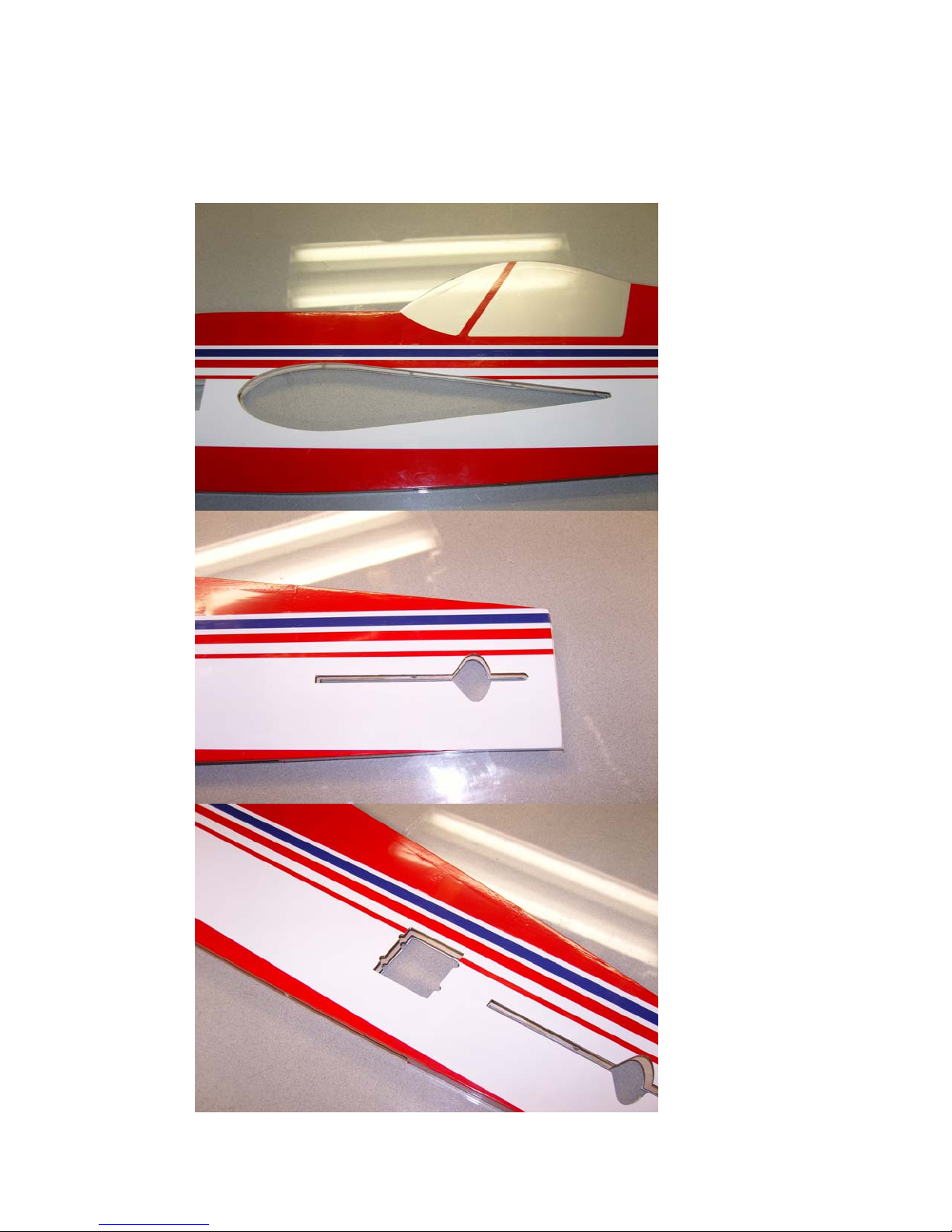
1. The first step is to use a sharp hobby knife to remove the covering from the wing
slot, stab slot and servo openings in the rear of the fuselage as shown in the
pictures.
3
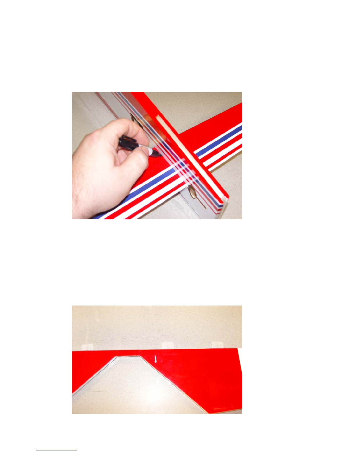
2. Now let’s install the horizontal stab and elevator. First insert the stab into its slot
in the rear of the fuselage. Use a ruler to assure the stab is centered and a square
to make sure it is aligned 90 degrees to the fuselage. Sand or shim the slot as
needed to insure proper alignment. Once satisfied use a fine felt tipped marker to
scribe the covering where it will need to be removed from the stab to allow a
wood-to-wood bond between the fuselage and stab.
3. Remove the stab and use an old soldering iron or sharp hobby blade to remove the
covering from the center of the stab. DO NOT GLUE THE STAB IN AT THIS
TIME!
4. Locate the elevator and the composite control horn and base. Open the slot in the
elevator to accept the control horn and place the base on the horn and insert in the
slot. Use a fine tipped marker to outline the base and then remove the horn
assembly. Use a blade to remove the covering under the base. You will need to
trim and sand the bottom of the horn so that it does not protrude through the top
surface. Scuff the portion of the horn that will be glued into the elevator and then
insert the horn into the base. Glue the horn and base into position with 30 minute
epoxy as shown.
4
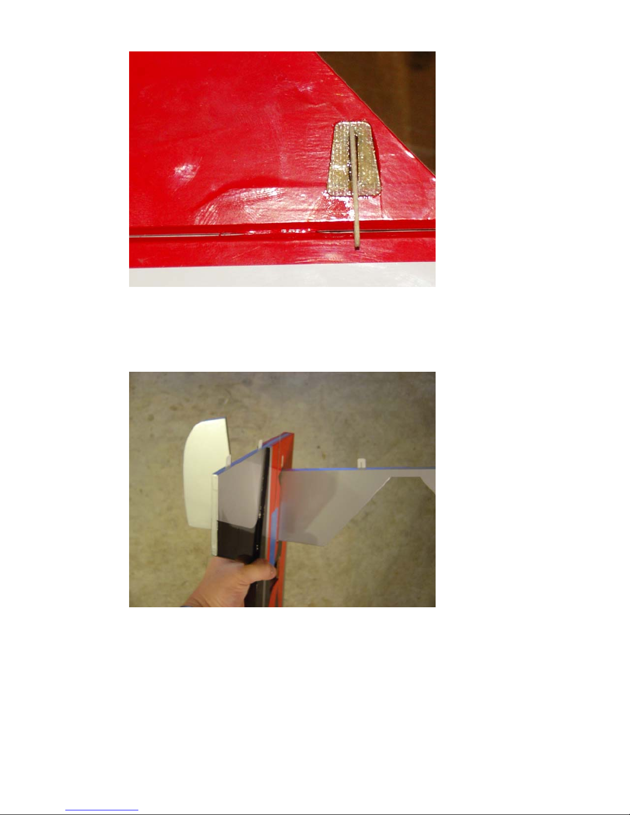
5. Slide the elevator through the stab slot oriented as in the picture, upside down
with the counter balances pointing toward the rear of the fuselage. Once in the
slot rotate the elevator into position. Now slide the stab into position. Re-check
alignment and glue in place with 30 minute epoxy. Once dry slide the elevator
onto the hinges and secure with thin CA. Be sure to leave enough gap to get
maximum deflection.
5
6. Locate the vertical fin and place it into the slot in the top rear of the fuselage.
Check to make sure it is properly aligned to the fuselage sides and at 90 degrees
to the horizontal stab, as well as flush with the rear of the fuselage. Sand or shim
the slot as needed for proper alignment. When satisfied glue in place with
30minute epoxy.
6

7. Locate the rudder, composite control horn and base, aluminum bracket, tailwheel
wire, wheel and 2 collars. Remove the covering from the slot for the rudder
control horn and insert the horn into the base and into the slot. Trace around the
base with a fine tipped marker and remove the covering from this area. Glue the
horn and base into position with 30 minute epoxy. You will need to trim and sand
the bottom of the horn to prevent it from protruding through the other side of the
rudder. Be sure to scuff the portion of the horn that will glue into the rudder for
best adhesion.
8. Slide a small wheel collar over the tailwheel wire and insert the tailwheel wire
into the hole in the aluminum mounting bracket. Use a set of pliers to bend the
wire to 90 degrees as shown, making sure the bend is perpendicular to the portion
of the wire where the tailwheel will mount.
9. Drill a hole in the bevel of the rudder to accept the wire just below the bottom
hinge. Slot the bevel to allow the vertical portion of the wire to be embedded.
Trial fit, and then secure with 30 minute epoxy, making sure to thoroughly coat
the wire and balsa. Use a piece of strapping tape to reinforce this area. Once dry
slide the tailwheel onto the wire and secure with a small wheel collar.
7

10. Slide the rudder onto the hinges and into position and secure with thin CA. Be
sure to leave enough gap to be able to get maximum deflection.
11. Secure the aluminum bracket to the bottom of the fuselage with 2 screws and
tighten the collar against the bracket.
8

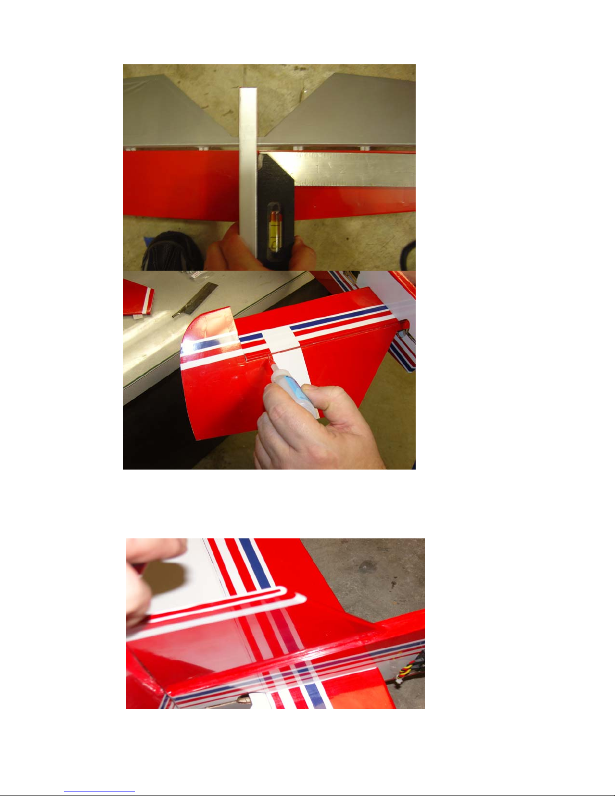
12. Next slide the wing into position and check alignment with fuselage and
horizontal stab. Measure to insure wing is positioned properly and then use a fine
tipped felt marker to mark the area where the covering will need to be removed to
insure a wood-to-wood bond between the wing and fuselage.
13. Remove the wing from the fuselage and use an old soldering iron or sharp hobby
knife to remove the covering from the center of the wing. Use some denatured
alcohol to remove any remaining ink.
14. Slide the wing into position just a few inches short of its proper location. Mix up
some 30 minute epoxy and apply to the exposed wood at the center of the wing
with an epoxy brush.
9

15. Slide the wing into position and check alignment from several angles to make
sure it is correct. Wipe away any excess epoxy with a paper towel soaked in
denatured alcohol. Re-check alignment and then set aside to dry. Once dry fill in
any gaps with thick CA.
16. Locate the 2 ailerons, 2 composite control horns and 2 base plates. Open the
covering over the slot on the bottom of the aileron and insert the control horn into
the base and into the slot. Use a fine tipped felt marker to trace the base plate and
remove the covering from this area.
10

17. You will need to trim and sand the bottom of the control horn so that it does not
protrude through the top surface. Scuff the portion of the control horn that will
glue into the slot and insert the horn into the base plate and secure to the aileron
with 30 minute epoxy. Repeat for the other aileron.
18. Slide the ailerons onto the hinges and into position and secure with thin CA.
11

19. Next let’s assemble the main landing gear and install them on the fuselage. If
flying off of tall grass you may want to forgo the wheel spats. Locate the 2 main
gear legs, 2 wheel spats, 2 axles with retaining nuts, 2 wheels, 2 collars and 2 ply
wood plates as well as 2 4mm bolts, washers and nuts.
20. Scuff the inside of the spats with sandpaper and glue the plywood plate to the spat
with 30 minute epoxy as shown. Repeat for the other spat.
21. Once dry drill a hole through the ply plate and spat as shown to accept the
threaded portion of the axle. Slide the threaded portion of the axle through the
spat and through the landing gear leg and secure with a nylon insert lock nut. The
friction of the washer on the axle will keep the spat in place.
12

22. Slide the wheels onto the axles and secure with wheel collars.
23. There are 2 holes pre-drilled in the outer layer of plywood near the front bottom
of the fuselage for mounting the landing gear. Locate these two holes and drill
completely through the fuselage with a 5/32” bit. Use the 4mm bolts, nuts and
washers to secure the main gear to the fuselage.
13

14

24. Use the manufacturer supplied hardware to install the 2 servos in the rear of the
fuselage as shown with the output shafts positioned toward the rear. It is best to
install the servos and then remove the screws and wick some thin CA into the
mounting holes before reinstalling the screws.
25. You will need to attach 24” extensions to the elevator servos to reach the radio
compartment inside the wing. There is a channel in the bottom of the fuselage
and the extensions are routed through an opening in the lower side of the fuselage
as shown.
15

26. Route the servo leads through the bottom of the fuselage and out of the pre-cut
slot and into the radio compartment in the wing through the pre-cut slot as shown.
27. Locate the provided strip of Ultracote and iron it into position on the bottom of
the fuselage.
16

28. Use the manufacturer supplied mounting hardware to install the 2 aileron servos
as shown. Be sure the output shaft is centered in the pre-cut hole.
29. Now let’s assemble and install the control linkages. Locate the 4 pushrods, 8 ball
links, 8 2mm bolts, nuts and washers. We also recommend the use of the Dubro
Super Strength servo arms. All of the linkages for the ailerons, elevator and
rudder assemble the same way. Electronically center your servos. Thread a ball
link onto each end of the pushrod. Insert a 2 mm bolt into a washer, through the
ball link and into the servo arm or control horn. Secure with another washer and
nut. Be sure to apply a drop of Loctite to prevent the linkage from coming apart
due to vibration. Please see picture for detail.
17

30. Your choice of engine will determine the location for your throttle servo. When
using the Saito .82 I have found it easiest to mount the servo to the hatch on its
side and cut a slot to allow the servo arm to protrude through the top of the hatch.
This provides a straight shot to the throttle arm. Other engines will require
slightly different linkage set-ups. We have provided you with a throttle pushrod
and nylon tube so that you may make a clean effective linkage through the leading
edge of the wing if necessary for your particular installation. Please see the photo
of our Saito .82 installation below.
31. You will want to save the installation of your engine for the last step so that you
can use its position to help achieve proper CG. Lighter engines like the 2 stroke
.46-.50 will need to be mounted further forward on the rails, while heavier
engines like the 4 stroke .82 will need to be mounted further aft. We recommend
installing your receiver and battery in the radio compartment in the wing opposite
the engine. Wrap your receiver battery in foam and place it inside the leading
edge of the wing and secure with Velcro. Once these components are installed
place your engine on the mounting rails with prop and spinner attached. For the
larger engines you may need to slightly trim the rails to make the engine fit
properly. A rotary tool makes quick work of this. Once satisfied with motor
position drill through the mounting lugs and secure engine with the provided 3mm
bolts, nuts and washers as shown. Be sure to place 2 washers between the 2 front
engine mounting lugs and fuselage to provide 2 degrees of right thrust to counter
spiral slipstream effect.
18
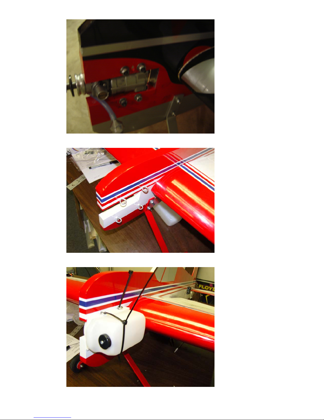
32. Install the 4 provided screw eyes as shown and secure each with a drop of
medium CA.
33. Secure the tank to the fuselage with nylon cable ties or rubber bands. Be sure to
place a piece of closed cell foam between the tank and fuselage side.
19

34. Run you fuel lines from the tank to the engine. We usually drill through the
fuselage to route fuel lines and help keep them out of the propeller.
35. Secure the radio compartment hatches with 4 screws each, installed 1at each
corner.
36. Apply decals, and that’s it! Assembly is done!
Set-up
According to designer Jeremy Chinn the CG range is 5”-5.75” from the leading edge of
the wing measured at the root. Jeremy says the ideal 3D CG is at 5.25”. Below are his
recommended rates and exponential preferences. You may wish to start with a bit more
exponential than this as the control surfaces are extremely effective!
High Rates Low Rates Expo
Elevator 50 degrees 25 degrees 20-40%
Rudder 50-60 degrees 30 degrees 30-50%
Ailerons 50 degrees 30 degrees 20-40%
Thanks again for your purchase of the Extreme Flight RC Yak-55SP Profile ARF. We
hope this airframe provides you with all of the 3D thrills you are looking for and that you
have as much fun flying yours as we have had with ours.
See ya at the flying field!
20
 Loading...