

Page 1

TURBO RAVEN EXP
69 inch electric ARF assembly manual
Copyright Extreme Flight 2019
1
Page 2

Please take a few moments to read this instruction manual in its entirety before beginning
assembly. We have outlined a fast, clear and easy method to assemble this aircraft and
familiarizing yourself with this process will aid in a quick, easy assembly.
Please read the following paragraphs before beginning assembly
of your aircraft!
THIS IS NOT A TOY! Serious injury, destruction of property, or even death may result
from the misuse of this product. Extreme Flight RC is providing you, the consumer, with a
very high quality model aircraft component kit, from which you, the consumer, will
assemble a flying model. As such it is beyond our control to monitor the finished aircraft
you produce. Extreme Flight RC will in no way accept or assume responsibility or liability
for damages resulting from the use of this user assembled product. This aircraft should be
flown in accordance with the AMA safety code. It is highly recommended that you join the
Academy of Model Aeronautics in order to be properly insured and operate your model at
AMA sanctioned flying fields only. If you are not willing to accept ALL liability for the use
of this product, please return it to the place of purchase immediately.
Extreme Flight RC, Ltd. guarantees this kit to be free of defects in materials and
workmanship for a period of 30 DAYS from the date of purchase. All warranty claims must
be accompanied by the original dated receipt. This warranty is extended to the original
purchaser of the aircraft kit only. Extreme Flight RC in no way warranties its aircraft
against flutter. We have put these aircraft through the most grueling flight tests imaginable
and have not experienced any control surface flutter. Proper servo selection and linkage
set-up is absolutely essential. Inadequate servos or improper linkage set up may result in
flutter and possibly the complete destruction of your aircraft. If you are not experienced in
this type of linkage set-up or have questions regarding servo choices, please contact us at
[email protected] or 770-887-1794. It is your responsibility to ensure the
airworthiness of your model.
2
Page 3

Greetings and congratulations on your purchase of the Extreme Flight RC 69 inch Turbo
Raven EXP! This revolutionary new airframe designed by our good friend Cody Wojcik
is insanely capable, precise, and pure feeling on just a 6S power system. This aircraft is
based on the short-lived full scale Turbo Raven piloted by Wayne Handley, which was
initially based on the Giles G-202 with extensive use of composites, and was one of the only
full scale aerobatic planes with a greater than one to one thrust to weight ratio. It was
capable of full 3D flight including flying straight out of flat spins, torque rolls and stop
and start vertical up lines.
With carefully analyzed moments and areas and a CFD analyzed airfoil, the Turbo Raven
EXP was designed from the outset to perform best at an extremely low wing loading that
would make more traditional designs feel sloppy, floaty, and imprecise. Its narrow
fuselage reduces drag and keeps the ailerons in the prop blast for maximum control at
near zero airspeed. Knife-edge requires no mixing and pitch response is as smooth as a
pattern plane and as powerful as an Edge when you yank on the stick. Huge,
counterbalanced ailerons mean the roll rate is fast but extremely predictable and
consistent, and it makes rifle rolls easier than any other airplane on the market. The clean
design also makes the Turbo Raven shockingly comfortable in the wind!
Paired with modern super torque mini servos such as the MKS HV9767 or Savox SV1260, DualSky G1500.5 and 17x6 prop (the Torque 4016T-500 and 16x7 will also work
well), and a 6S 3700-4500 battery, the Turbo Raven offers unprecedented performance in
an extremely affordable and convenient package.
3
Page 4
Tips for Success:
1. Before starting assembly, take a few minutes to read the entire instruction manual to
familiarize yourself with the assembly process.
2. Please take a few minutes and go over all the seams on the aircraft with a covering iron
on a medium heat setting.
3. Apply a couple drops of CA to high stress areas such as anti-rotation pins, landing gear
mounts, servo trays and motor box joints .
4. When applying decals, first clean the area where the decal will be applied with alcohol.
Mist the area lightly with Windex or Rapid Tack before applying the decal which will
allow you to properly position it, then use a rubber squeegee to push all of the liquid from
under the decal. This will result in very few air pockets trapped under the decal.
5. Take the time to properly balance and trim your aircraft and set up rates and
exponential values. Your flying experience will be greatly enhanced by doing this.
The Ultracote colors used on the Turbo Raven are as follows:
True Red #HANU866, Pearl Dark Yellow #HANU843, Midnight Blue #HANU885, White
#HANU870 and Transparent Blue #HANU954
4
Page 5

Items needed for completion
-Masking tape.
-Hobby knife with #11 blades.
-Hobby sealing iron.
-Thin and medium CA. We highly recommend Mercury M5T thin and M100XF medium
formulas as well as the Mercury glue tips.
-Pacer Formula 560 Canopy Glue.
-Silicon glue (Goop)
-Blue Loctite.
-Electric drill with an assortment of small drill bits.
-Small flat head and Phillip's head screw drivers.
-Standard and needle nose pliers.
-Metric balldriver or allen key set.
-Sanding block and sandpaper.
-4 high torque mini metal geared servos. All flight testing was performed with MKS 9767
and Savox 1260 servos.
-Extreme Flight 1.25" lightweight servo arms (Qty 3) and 3" double arm with 2mm holes
(Qty 1)
-Torque 4016T/500 Brushless or Dualsky GA1500.5 Brushless Outrunner motor.
-Airboss Elite 80 Amp ESC for Torque motor or Dualsky Summit 120 for Dualsky motor.
-6S 3700-5000 mah LiPo battery.
- 16x7 Xoar PJN Electric wood prop for Torque motor or Xoar 17x6 PJN Electric wood
prop for Dualsky motor.
1-24" 28 AWG extension for elevator servo
2-6" 28 AWG extensions for aileron servos
2-3" 28 AWG extensions for receiver-aileron interface
1-12" 20 AWG extension for ESC to receiver
-Adhesive backed Velcro and Velcro strap for battery retention.
5
Page 6
Let's begin!
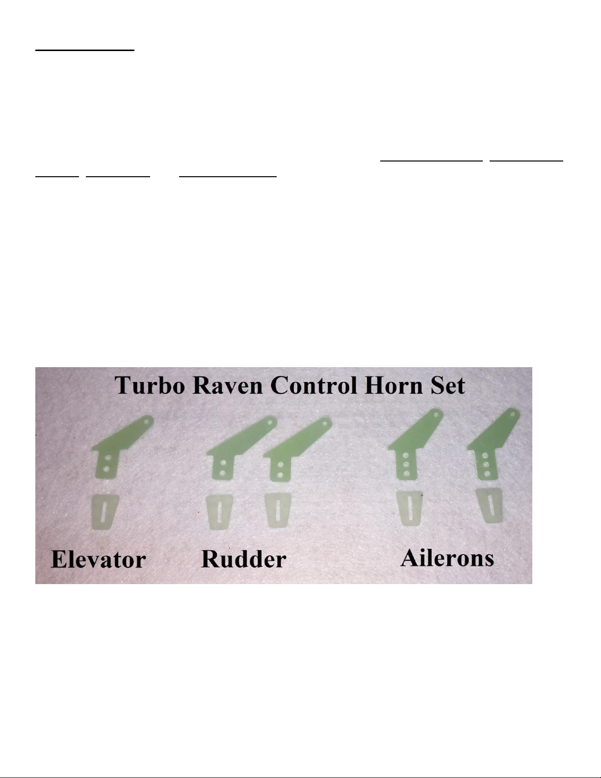
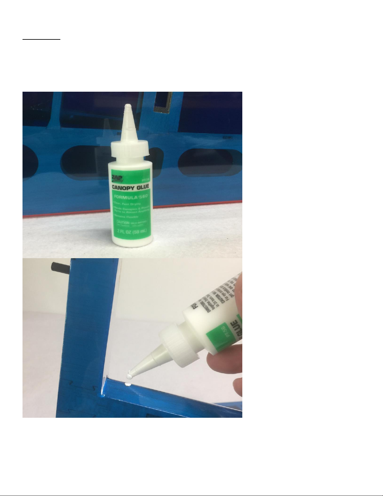
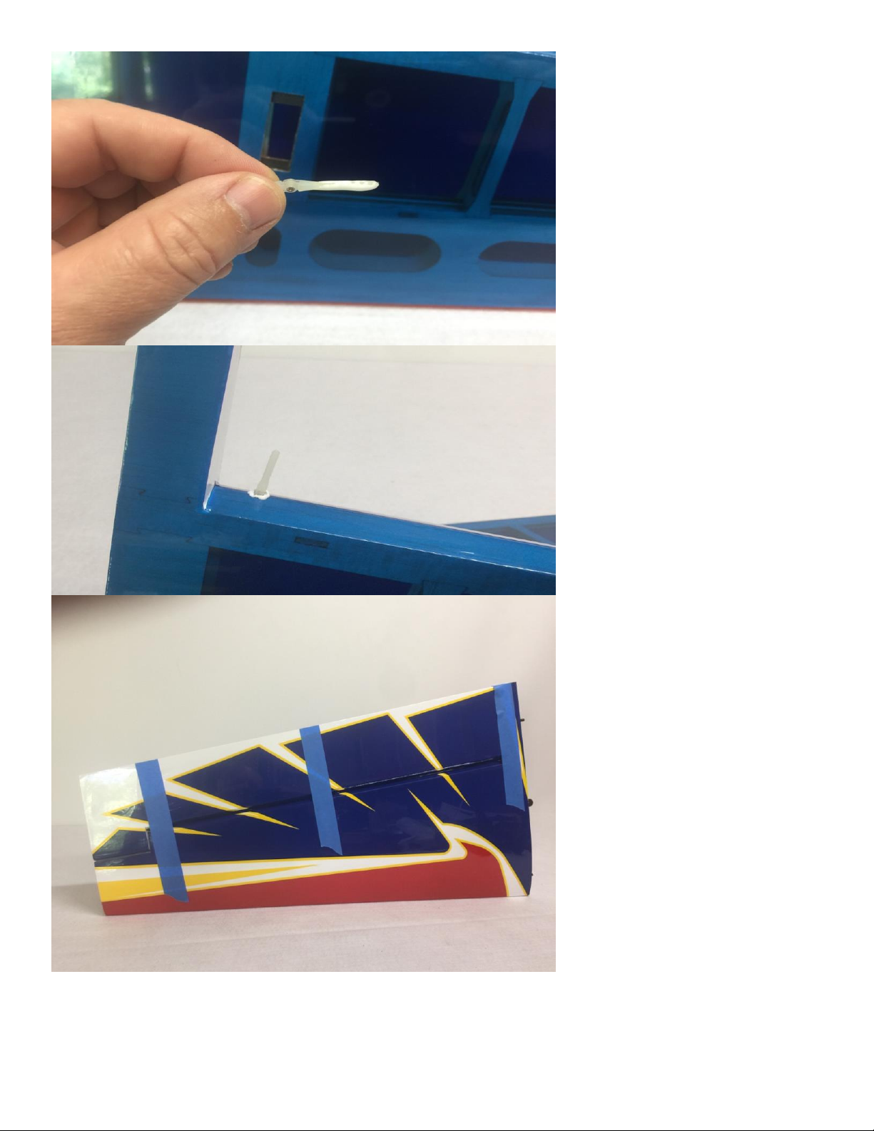
1. Locate the 2 wing panels with ailerons as well as the 2 G10 aileron control horns and base plates.
Remove the aileron and pull the hinges from the wing and aileron. Use Pacer Formula 560 Canopy Glue
to secure the hinges. This glue works very well in this application and cleans up easily with water. Apply
the glue to both the hinge holes and the hinges themselves and push the surfaces together leaving a
minimal gap between them. Use masking tape to keep the aileron in position while the glue sets. Wipe
away any excess glue with a damp paper towel.
6
Page 7
7
Page 8
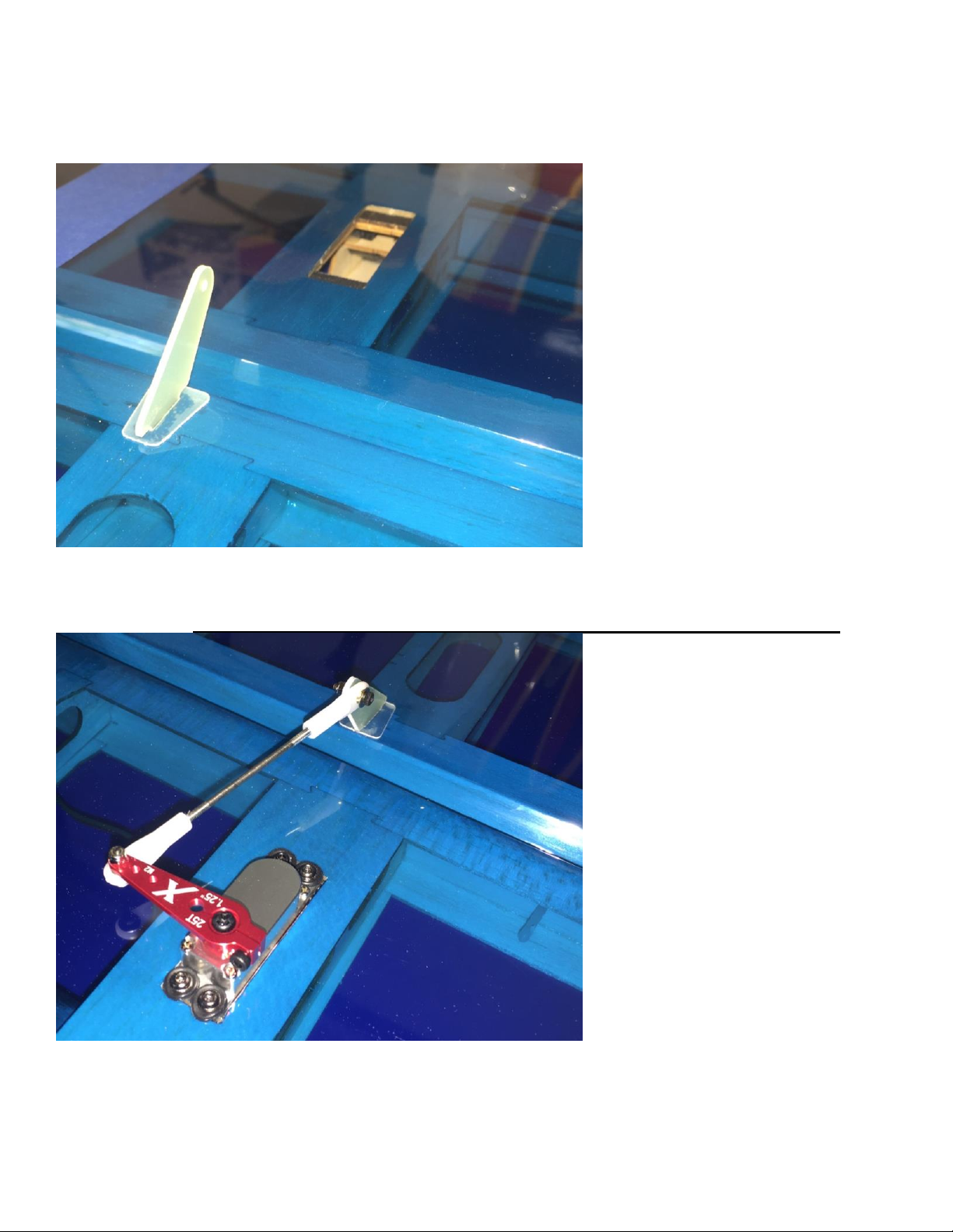
2. Remove the covering over the slot for the aileron horn on the bottom of the aileron with a sharp hobby
blade. Make sure you are doing this on the bottom of the aileron! Insert the horn into the base plate and
into the slot in the aileron. Use a fine tipped felt marker to trace the base plate. Use a sharp blade to
remove the covering under the base plate. Scuff the control horn's gluing surface with sandpaper and
glue the horn and baseplate in place with medium CA.
3. Attach a 6" servo extension to your aileron servo and secure with an Extreme Flight Servo Safety Clip
or a piece of heat shrink tubing. Secure the servo into the slot with the output spline facing the leading
edge of the wing. Assemble and install the aileron linkage as shown in the picture using the provided
2mm hardware. Please note the ball link and pushrod are mounted to the bottom of the servo arm.
8
Page 9
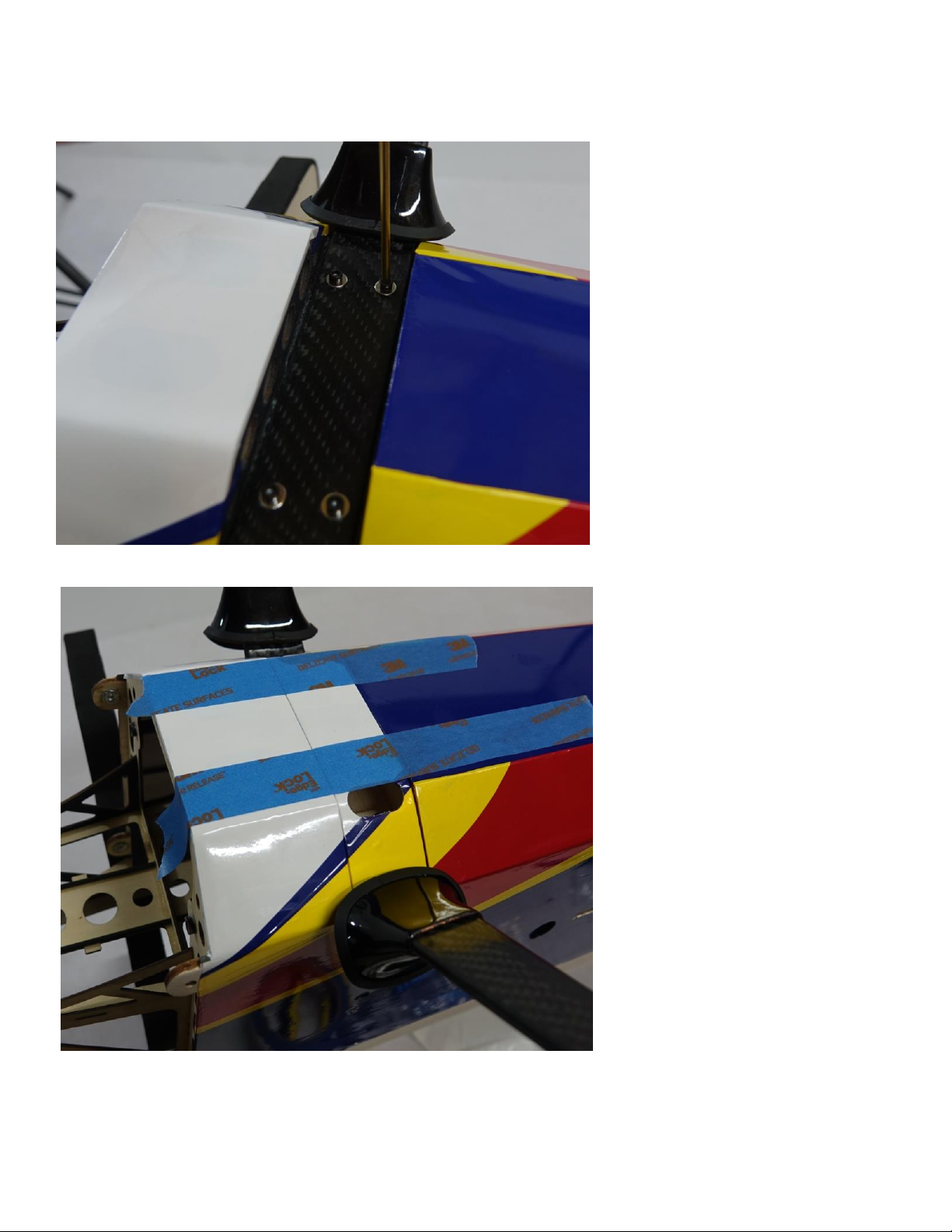
4. Locate the fuselage, carbon fiber main gear, wheel pants, fairings, wheels, axles and related hardware
for mounting the landing gear. Use the provided mounting hardware to secure the main gear to the
fuselage. Be sure to apply blue thread lock to the bolts before inserting into the gear and pre-installed
blind nuts.
5. Secure the landing gear cover to the carbon gear with a couple beads of white glue or silicon glue and
tape in place until the glue sets.
9
Page 10
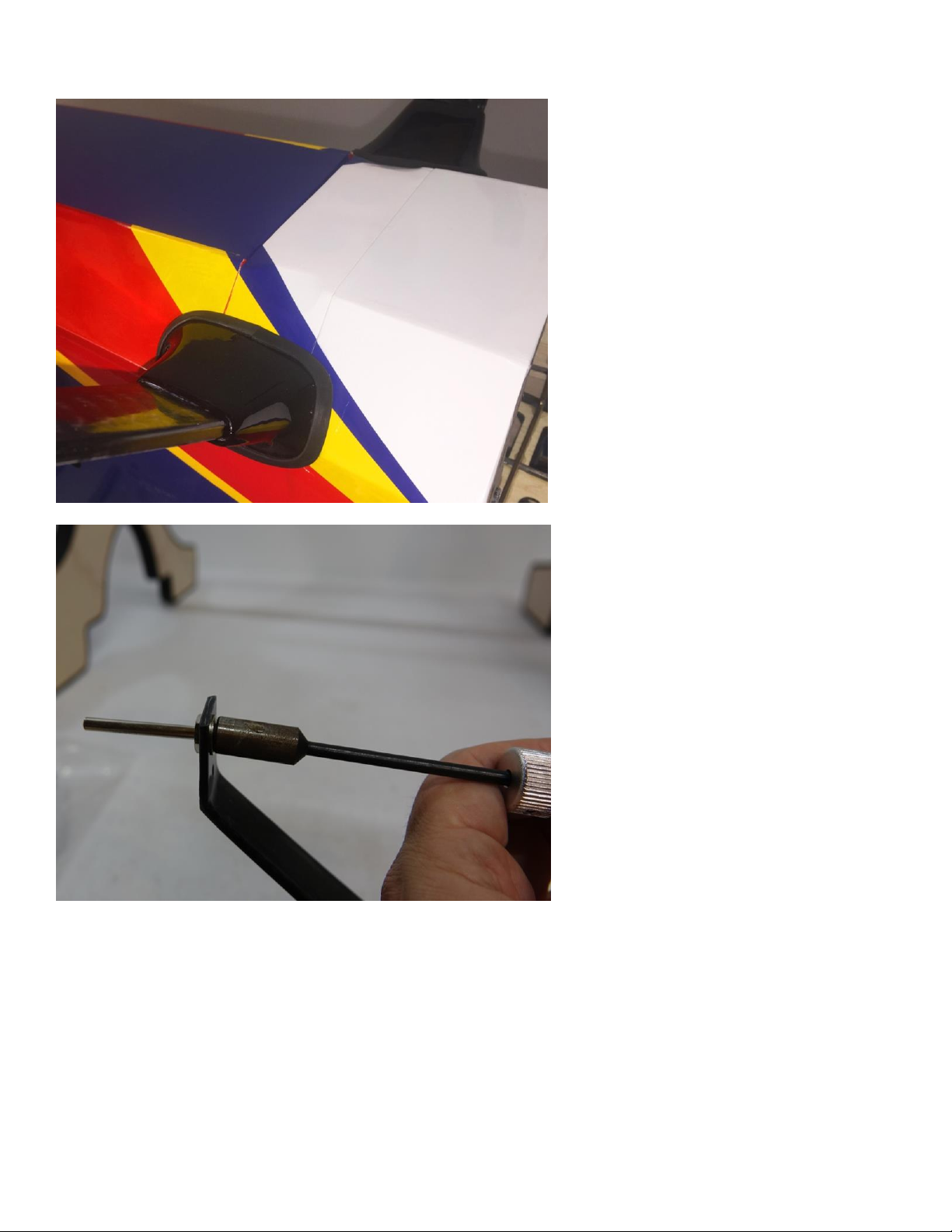
6. Glue the landing gear fairings into place against the fuselage side with silicon glue or medium CA
applied to the carbon gear leg.
7. Secure the provided axles to the landing gear with a washer and nylon insert lock nut.
10
Page 11
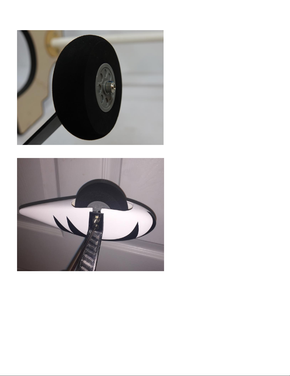
8. Slide the wheel onto the axle and secure with a wheel collar. Be sure to apply Blue Loctite to the set
screw in the wheel collar.
9. Slide the wheel pants into position and secure with a 3mm bolt. You may need to open the slot in the
wheel pant for proper fit over the axle. Again use Blue Loctite on the bolt.
11
Page 12
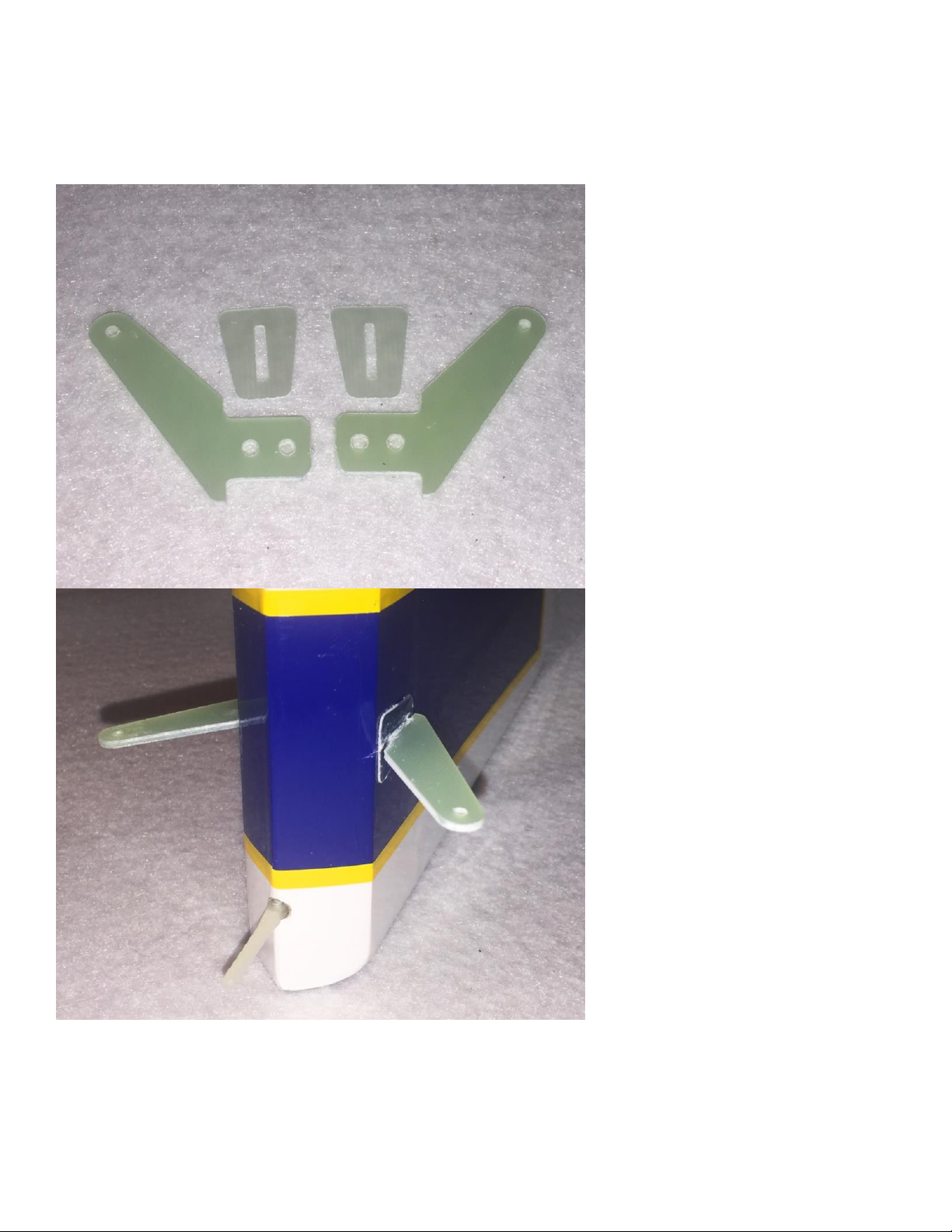
10. Locate the rudder and rudder control horns and base plates. Trial fit the horns into position in their
pre-cut slots and confirm alignment. Trace around the baseplate, and remove the covering under the
baseplate. Glue the horns into position using 30 minute epoxy. Wipe away any excess epoxy with a paper
towel soaked in denatured alcohol, re-confirm alignment and set aside to dry. Once dry glue the rudder
into place on the vertical stabilizer using the same method to glue the hinges in place as previously
described.
12
Page 13
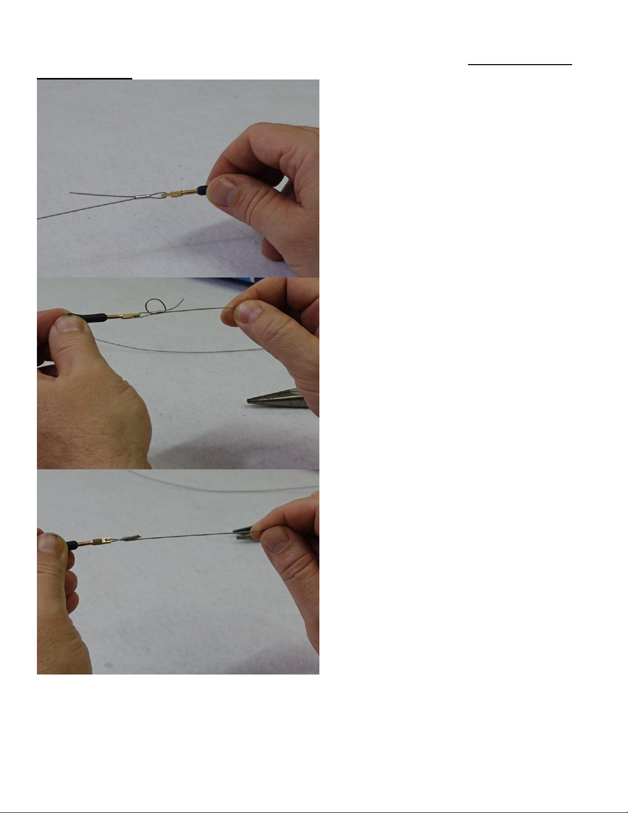
11. Mount the rudder servo in the rudder tray in the fuselage. Assemble the pull-pull cables as shown
and secure to the servo arm and control horns with the provided 2mm hardware. The pull-pull cables
should be crossed.
13
Page 14
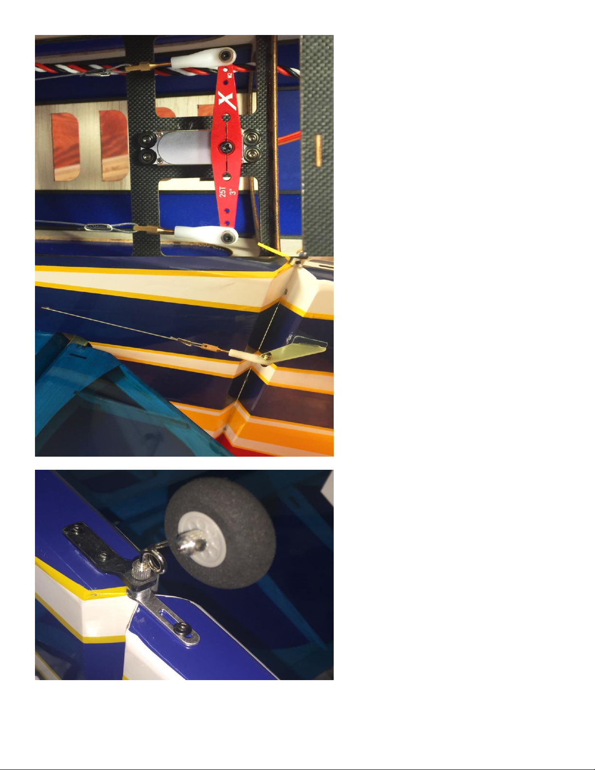
12. Install the tailwheel assembly as shown.
14
Page 15
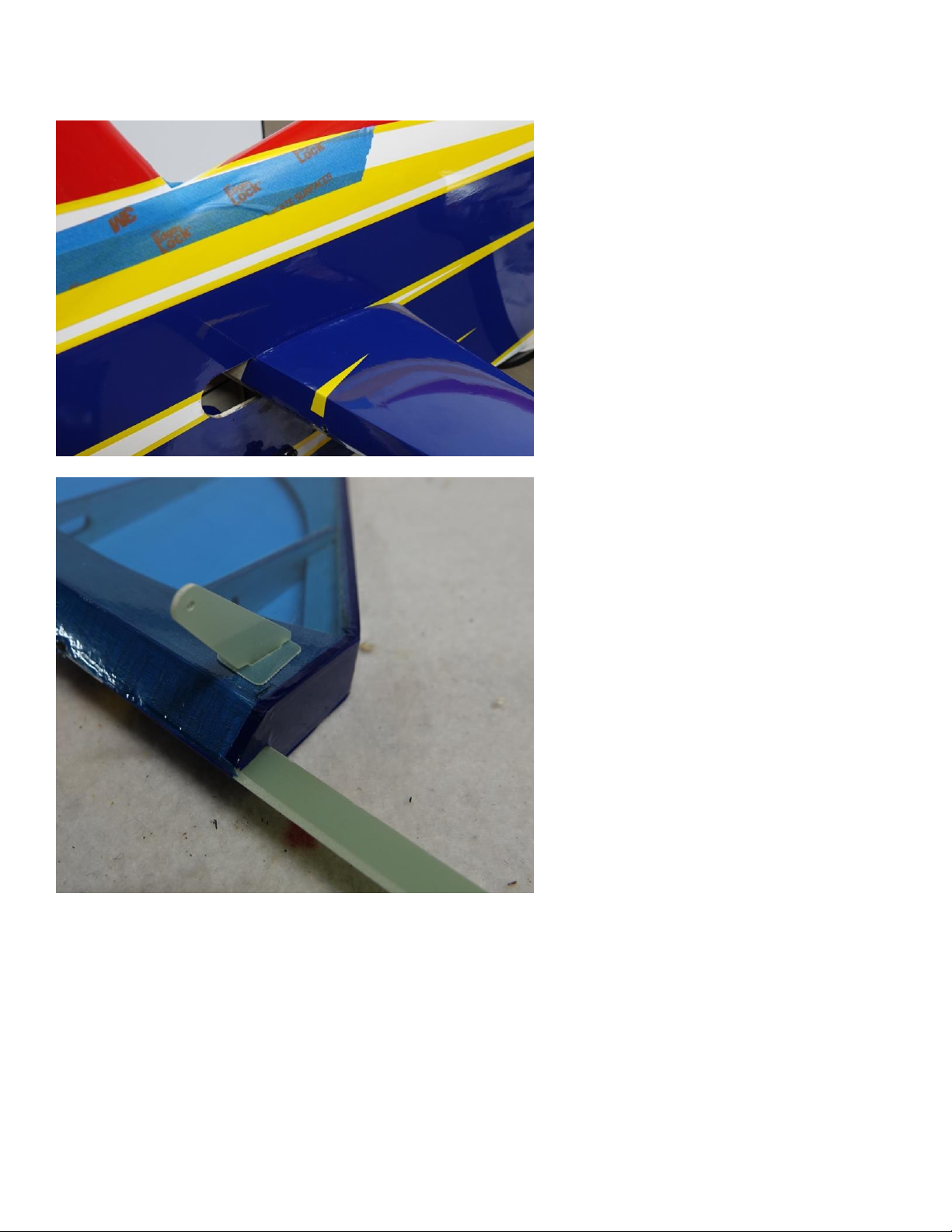
13. Locate the horizontal stab/elevator assembly. Remove the elevator from the stab. Insert the stab
into the fuselage and the wing tube into its socket and confirm alignment. Glue the stab in place with a
combination of thin and medium CA.
14. Glue the elevator horn and baseplate into position on the bottom left elevator with medium CA.
15. Lightly sand the composite elevator joiner and then glue the left elevator half onto the stab using
Formula 560 glue on the hinges.
15
Page 16
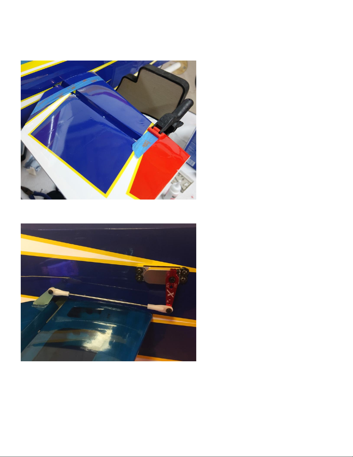
16. Coat the portion of the elevator joiner that will insert into the slot in the right elevator half with 30
minute epoxy. Coat the slot in the elevator with epoxy as well. Apply glue to the hinges and hinge slots
and push the assembly together. Clean up the excess glue and then secure with masking tape until dry.
Use a small clamp to ensure that the counterbalances stay aligned with the elevator during the drying
process.
17. Attach a 24" servo extension to the elevator servo and secure with an EF servo safety clip or heat
shrink tubing. Install the elevator servo and assemble the linkage using an Extreme Flight 1.25"
lightweight aluminum servo arm and the provided 2mm hardware as shown.
16
Page 17
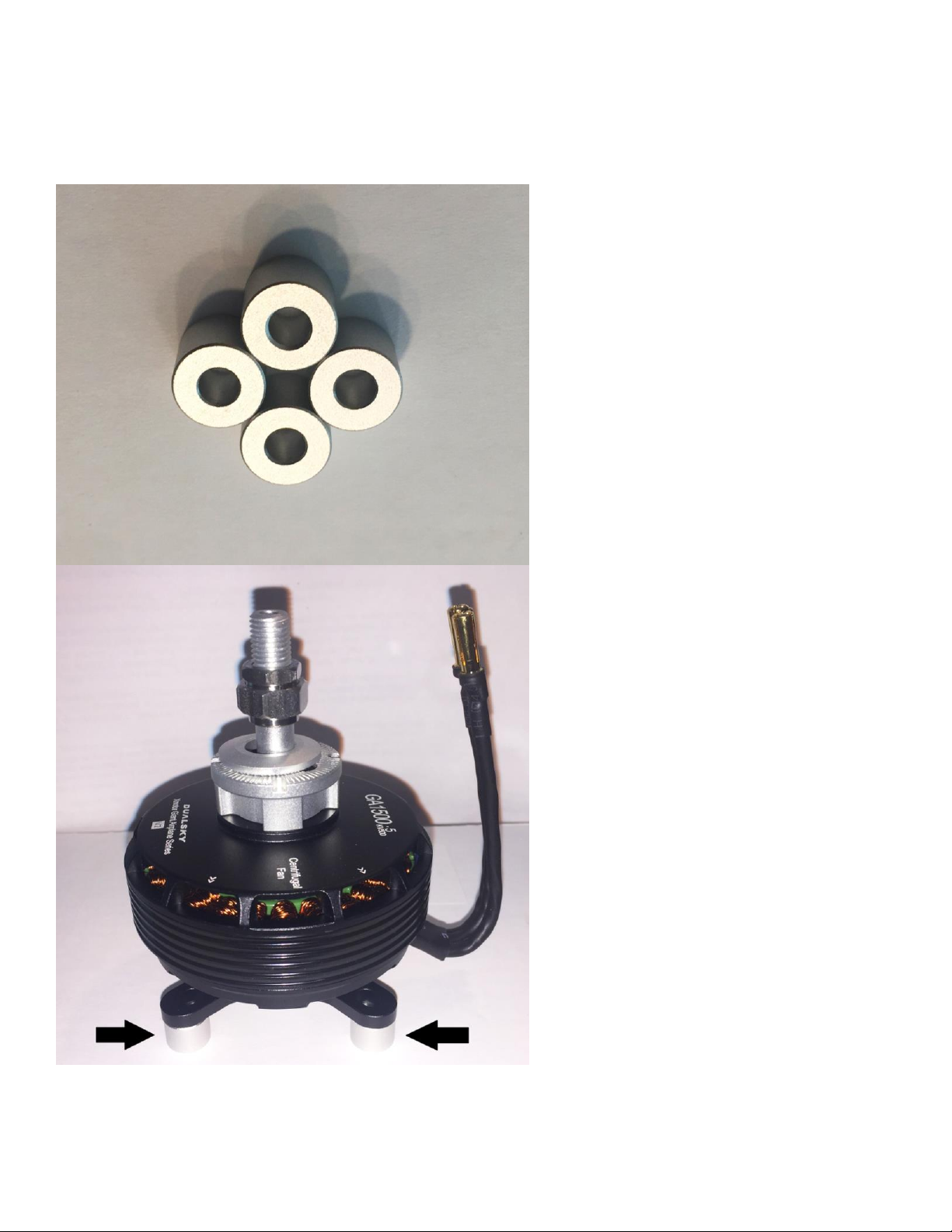
18. Prepare your motor of choice for mounting by attaching the prop adapter and radial mount. If using
the Dualsky G-1500.5 outrunner you will need to remove the radial mount and secure it to the motorbox
first.
19.The Dualsky G-1500.5 motors that Extreme Flight supplies include 8mm standoffs that were specially
made by Dualsky to get the total length of the motor to the same length as the Torque 4016/500. Use
these standoff when mounting the G-1500.5 in the Turbo Raven.
17
Page 18
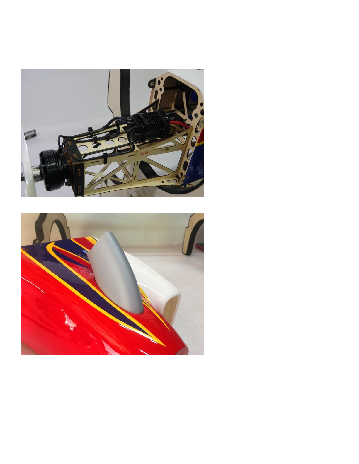
20. Install your choice of motor with the provided 4mm mounting bolts making sure to use a generous
amount of Blue Loctite on each bolt. Mount the ESC on the bottom of the motor box and secure the
motor wires to keep them from flapping around and getting chaffed. I used a piece of scrap foam
padding to protect the ESC from vibration and secured the ESC with nylon cable ties. ***Please note at
the time this picture was taken we had yet to receive the aluminum standoffs so a wooden spacer was
fabricated.***
21. Glue the turbine exhaust stacks into the recesses in the cowl with medium CA or Goop silicon glue.
Be sure to sand the mating surfaces for best adhesion.
18
Page 19
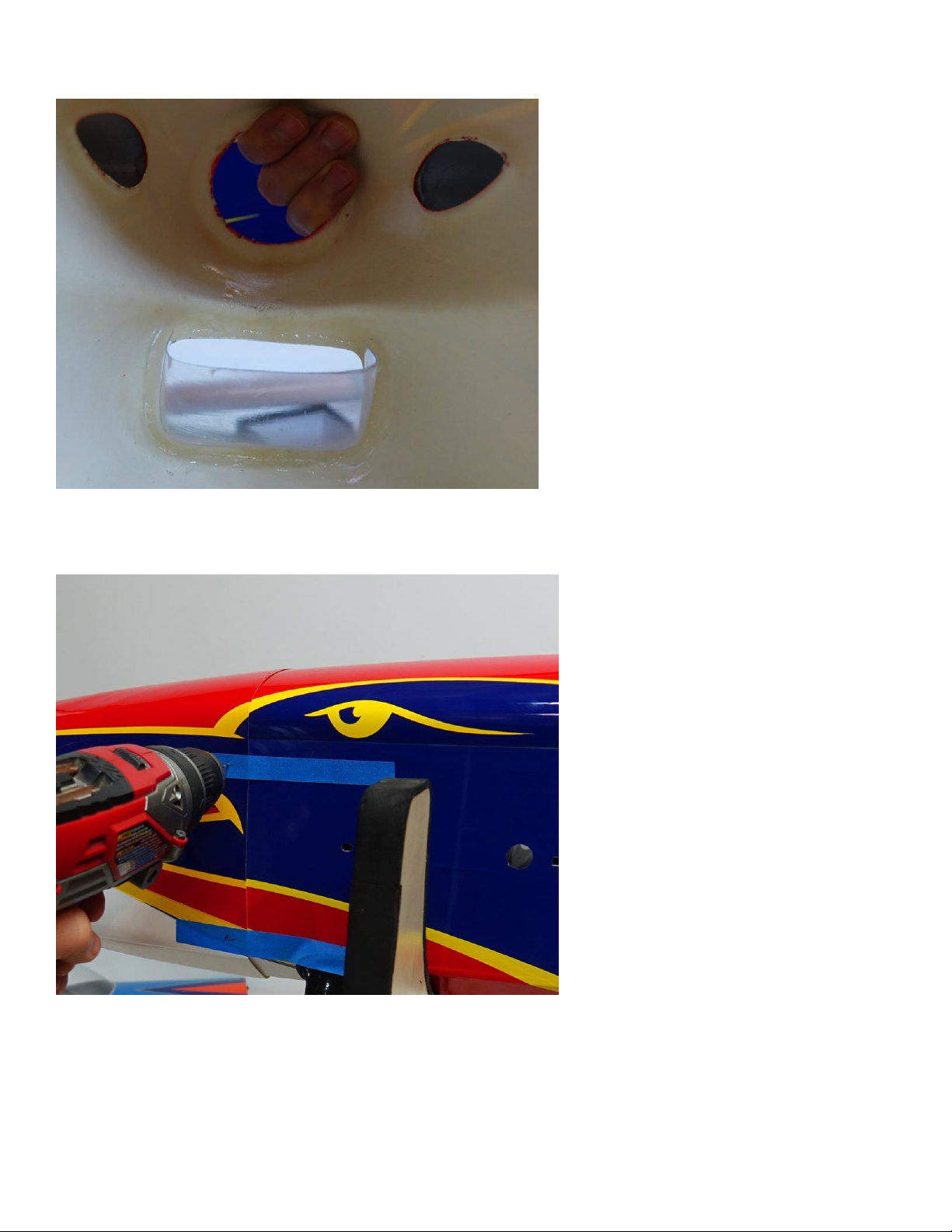
22. Trim and glue the clear air scoop into the opening in the lower portion of the cowl with medium CA
or Goop.
23. Cut 4 strips of masking tape from the roll. Place the strips onto the fuselage and mark the location of
the blind nuts that are installed in the cowl mounting tabs with a felt tip pen. Roll the tape back and slide
the cowl into position using the spinner to help with alignment. When satisfied roll the tape back into
position to secure the cowl. Use a 1/16" drill bit to drill a pilot hole at each of the 4 mounting locations.
19
Page 20
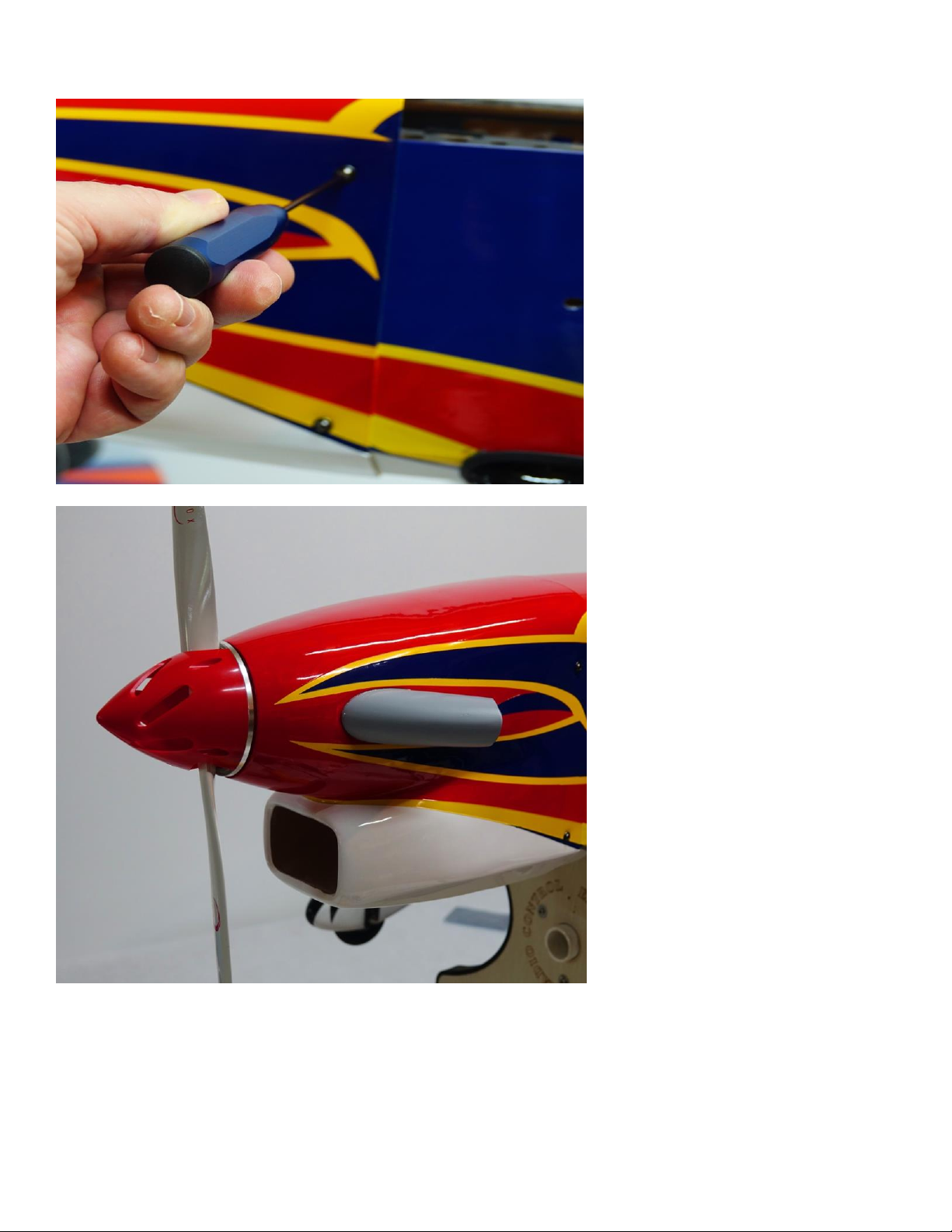
24. Open the holes to accept the 3mm bolts and secure the cowl with 4 3mm bolts and washers. Be sure
to apply a drop of Blue Loctite to each bolt.
25. Mount your choice of prop and the included Cyclone vented spinner.
20
Page 21
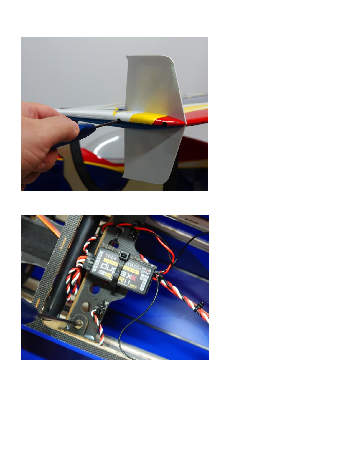
26. Secure the SFGs and wing tips to the wing with 2 3mm bolts.
27. Slide the wing tube into the fuselage and slide the wings onto the tube. Secure with 2 3mm bolts and
washers inserted through the wing retention tabs and into the pre-installed blind nuts. Use a drop of
Blue Loctite on the bolts.
28. Mount your receiver on the tray behind the wingtube as shown in the previous picture.
29. Attach a strip of Velcro to the battery tray and use a Velcro strap to secure your battery.
21
Page 22

Set-up and flying tips
I have found the ideal CG for the Turbo Raven to be at the center of the wing tube. This is a safe place to
start and depending on your flying style you can adjust the position of the battery to alter the CG to
accommodate your preferences. For this type of aircraft where I am going to predominantly fly
aggressive 3D I typically set the airplane up with a neutral CG, meaning that when the aircraft is flown
inverted straight and level it requires no down elevator to maintain altitude. If your flying style leans
more toward precision aerobatics then I recommend setting your CG using the 45 degree line test. Fly
the aircraft from left to right or right to left, whichever direction you are more comfortable with at 3/4 to
full throttle. Pull the aircraft to a 45 degree up line and establish this line and immediately roll the
aircraft inverted. Establish this line and let go of the elevator stick. Ideally the aircraft will continue to
track on that 45 degree line for several hundred feet before slowly starting to level off. Adjust the
position of your battery to achieve this flight condition. Once satisfied with the location of your CG
scribe a mark on the battery tray so that you can position the battery in the same location each flight and
achieve the same feel and flight characteristics each flight.
I also highly recommend taking the time to properly set up your rates and exponential settings. Setting
up low rates for precision maneuvers and high rates for aggressive aerobatics and 3D flight will allow you
to experience the best attributes of the Turbo Raven or any aircraft for that matter. Here are some
suggested rates to get started with. These are the rates and exponential values I feel comfortable with.
They may not be optimal for you so please adjust to your taste.
Elevator: Low rate-8-10 degrees; 15-20% Exponential
3D rate-45-60 degrees; 60-65% Exponential
Rudder: Low rate-20 degrees; 45-50% Exponential
3D rate- 50 degrees; 50-60% Exponential
Aileron: Low rate-15-20%; 40-45% Exponential
3D rate- 40 degrees; 50-60% Exponential
Again, these are my preferences, adjust to suit your flying style and preferred feel.
A huge thanks goes out to Cody Wojcik for all his work on this very unique aircraft. It is a joy and
honor to have the Turbo Raven in our lineup and to be able to offer it to our customers. Enjoy!
See ya at the flying field!
Chris Hinson
Extreme Flight
22
 Loading...