

Page 1
6S 3000-5000mah
A V I A T I O N
7.5-8.5 lbs / 3.4-3.9 kg
Page 2
Please read the following paragraphs before beginning assembly of your aircraft!
THIS IS NOT A TOY! Serious injury, destruction of property, or even death may result from the misuse of this
product. Extreme Flight RC is providing you, the consumer with a very high quality model aircraft component
kit, from which you, the consumer, will assemble a flying model. It is beyond our control to monitor the finished
aircraft you produce. Extreme Flight RC will in no way accept or assume responsibility or liability for damages
resulting from the use of this user assembled product. This aircraft should be flown in accordance to the AMA
safety code. It is highly recommended that you join the Academy of Model Aeronautics in order to be properly
insured, and to operate your model at AMA sanctioned flying fields only. If you are not willing to accept ALL
liability for the use of this product, please return it to the place of purchase immediately.
Extreme Flight RC guarantees this kit to be free of defects in materials and workmanship for a period of 30
DAYS from the date of purchase. All warranty claims must be accompanied by the original dated receipt. This
warranty is extended to the original purchaser of the aircraft kit only.
Extreme Flight RC in no way warranties its aircraft against flutter. We have put these aircraft through the most
grueling flight tests imaginable and have not experienced any control surface flutter. Proper servo selection
and linkage set-up is absolutely essential. Inadequate servos or improper linkage set up may result in flutter
and possibly the complete destruction of your aircraft. If you are not experienced in this type of linkage set-up
or have questions regarding servo choices, please contact us at info@extremeflightrc.com or 770-887-1794.
It is your responsibility to ensure the airworthiness of your model.
SPECIAL NOTE ABOUT HARDWARE
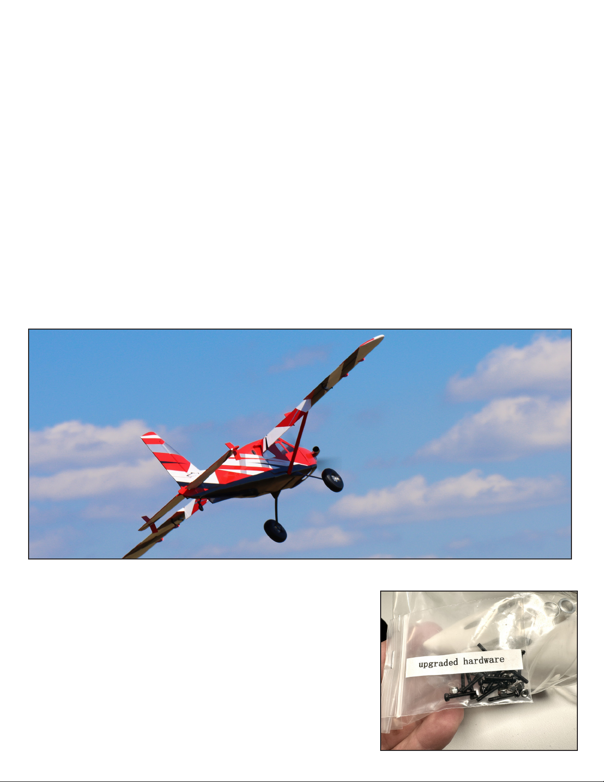
Your kit includes both original and UPGRADED screws and nuts for
your pushrods. The upgraded screws are black oxide coated and use
nylon locking nuts. Please use this upgraded hardware in your build.
The upgraded hardware is packed in a bag attached to the spinner
packaging.
Page 3
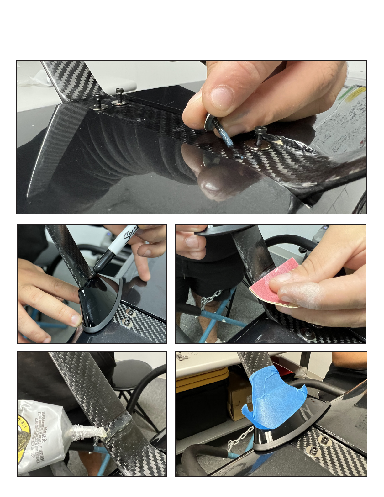
Attach the landing gear to the fuselage with the 4 included screws and washers. Use blue loctite thread
locking compound on these screws. Test t the berglass landing gear fairings, and mark the location onto
the landing gear. Sand the area and apply “Goop” or other rubberized adhesive and install the fairing.
Apply tape and allow to dry.
Page 4
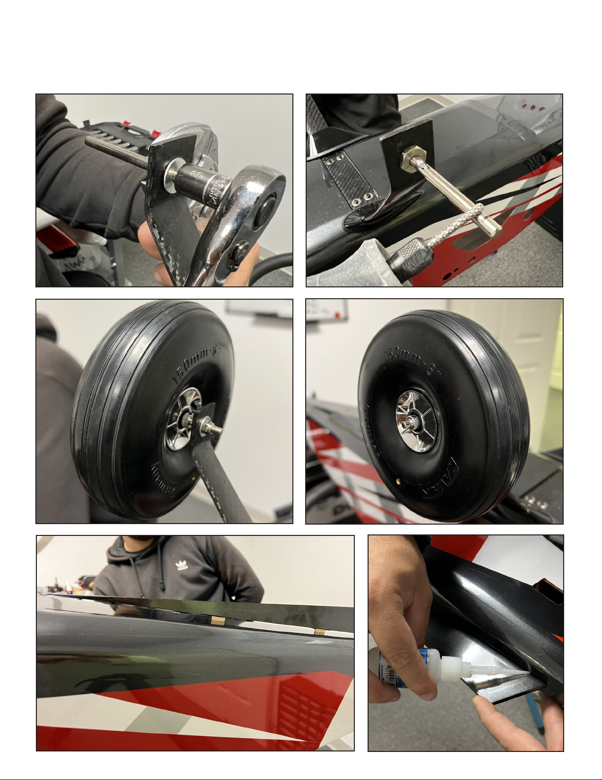
Using the washer and locking nut, attach the axle to the landing gear. We recommend to grind small
at areas into the axle as shown to help the set screws in the wheel collars to grip the axle better. Install one collar (using loctite on the set screw), then the wheel, then the second collar. NOTE we are
showing the optional KAVAN upgrade wheel available from Extreme Flight RC. Locate the bottom
n, remove covering over its installation slots in the fuselage, and install as shown using CA glue.
Page 5
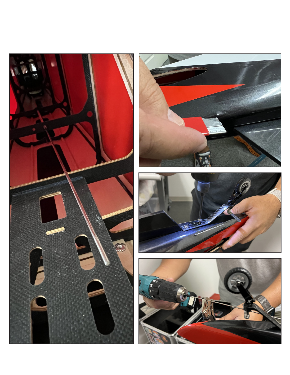
Locate the tailwheel pushrod, packed in the wing bag. Push the pushrod through its guide tube to create a dimple in the covering and cut the covering so the pushrod emerges from the fuselage as shown.
Attach the tailwheel to the fuselage using the included screws and blue loctite. Screw the ball link connector onto the pushrod (here we use a cordless drill) and attach to the tailwheel tiller with 2mm screw
and locknut.
Page 6
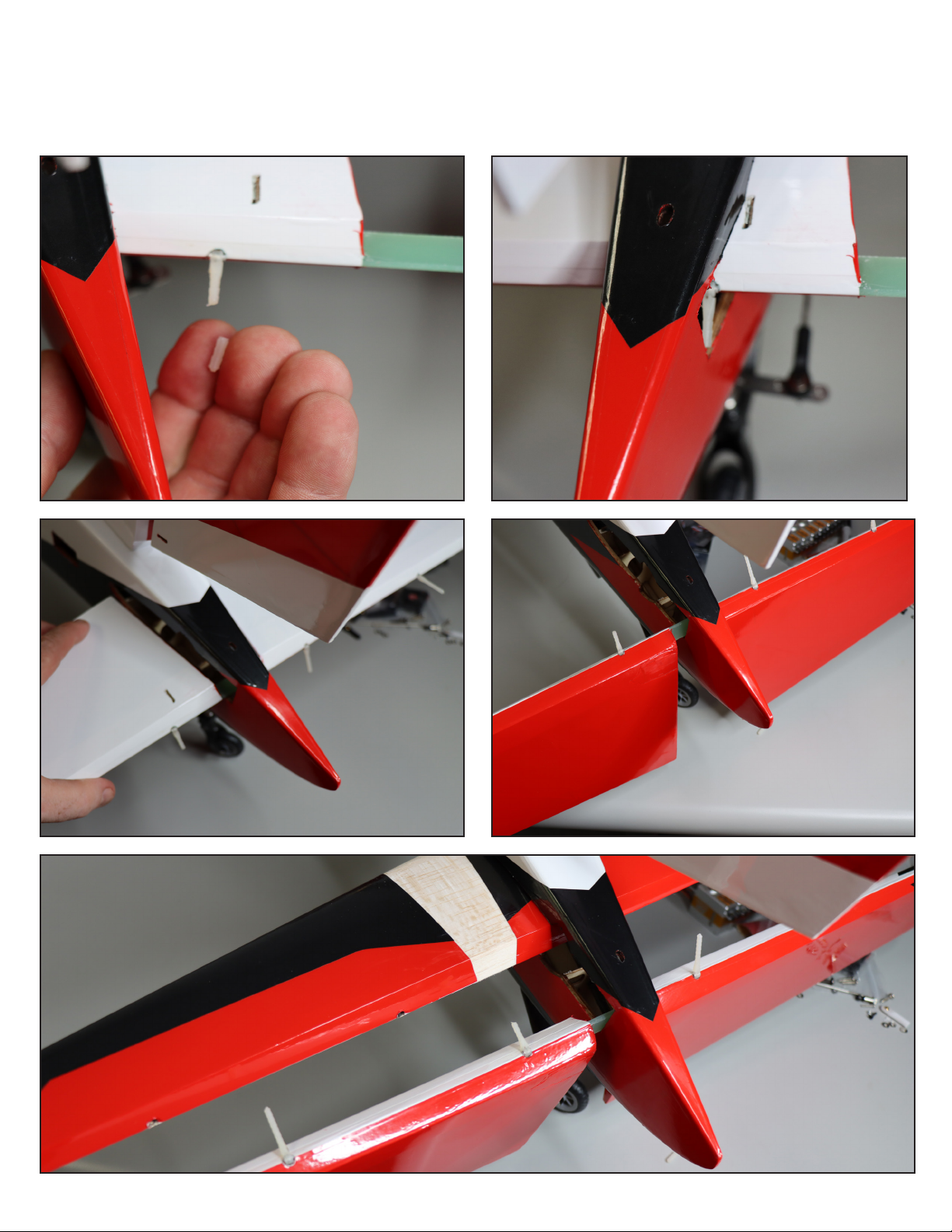
e elevator inserts through the opening in the rear of the fuselage, upside down and backwards, and then aer it is centered, ip it over to the proper position. When you insert
the elevator, one of the hinge points will be a tight t. Don’t risk breaking this hinge point,
instead trim o about 3/8” (8mm), so you can slide it through. en insert the horizontal
stabilizer as shown.
Page 7
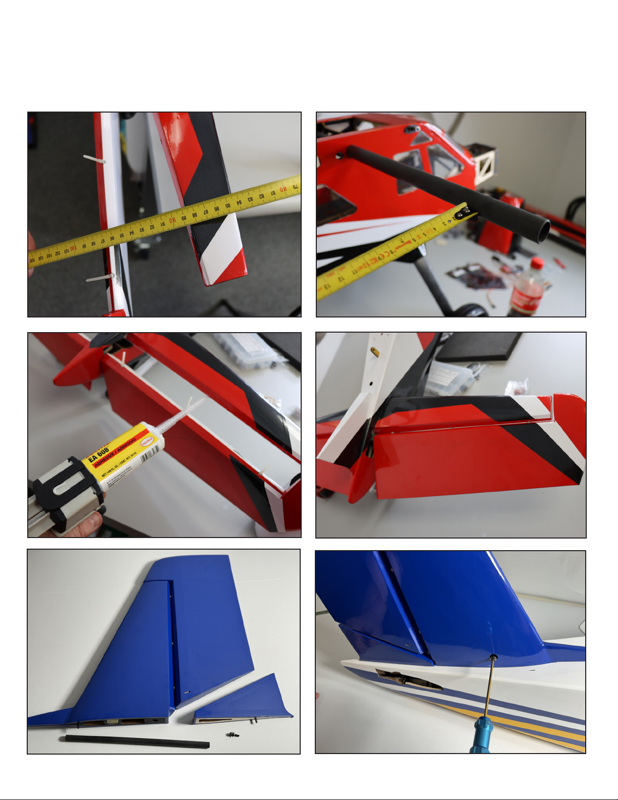
Use a tape measure to check the alignment of the horizontal stabiliser to the wing tube, and glue in
place with thin CA. Clean up any CA drips with acetone. Use epoxy glue to install the hinges into
the stabilizer, make sure the elevator moves freely. Allow to cure. e vertical stabilizer and rudder
install with a carbon tube and 3mm screw. Use loctite on this screw. Glue the ller piece between
the rudder and fuselage with CA glue.
Page 8
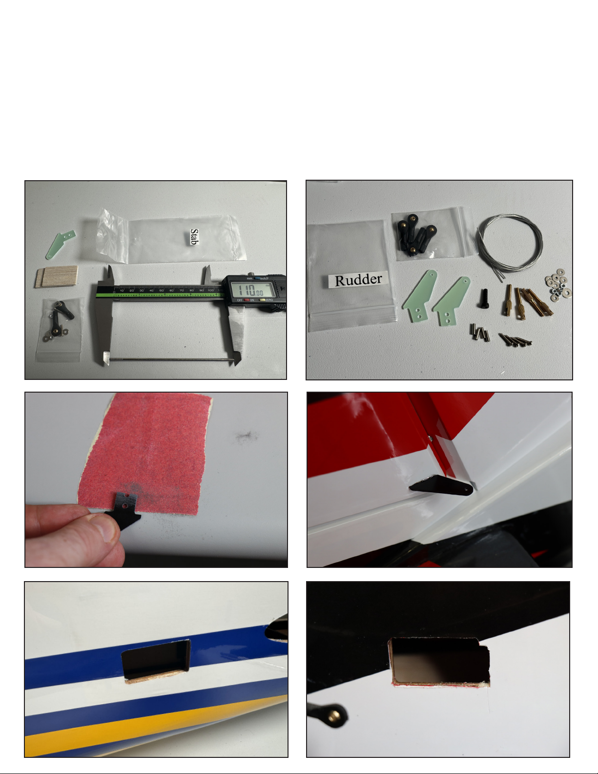
Locate the hardware for the Stab and Rudder.
Installing control horns: All of the control horns on your aircra install in the same way. Locate the correct control horn for each surface. Prep the horns by lightly scung the gluing area (the part which will
go into the control surface) with sandpaper or an emery board. Test t the horn without glue to make
sure it goes all the way into the surface as shown. To permanently install the horn, place medium CA
glue into the slot, insert the horn fully and rmly into the slot, and then add a few drops of thin CA.
e 84”Bushmaster can be own as a gentle sport yer, or a high power STOL/3D plane. For slower
ight, it can use smaller servos, and the servo openings in the kit are 33mm long. To t higher performance servos such as Savox 1261 or eta 989, open the servo locations to 35mm long.
Page 9
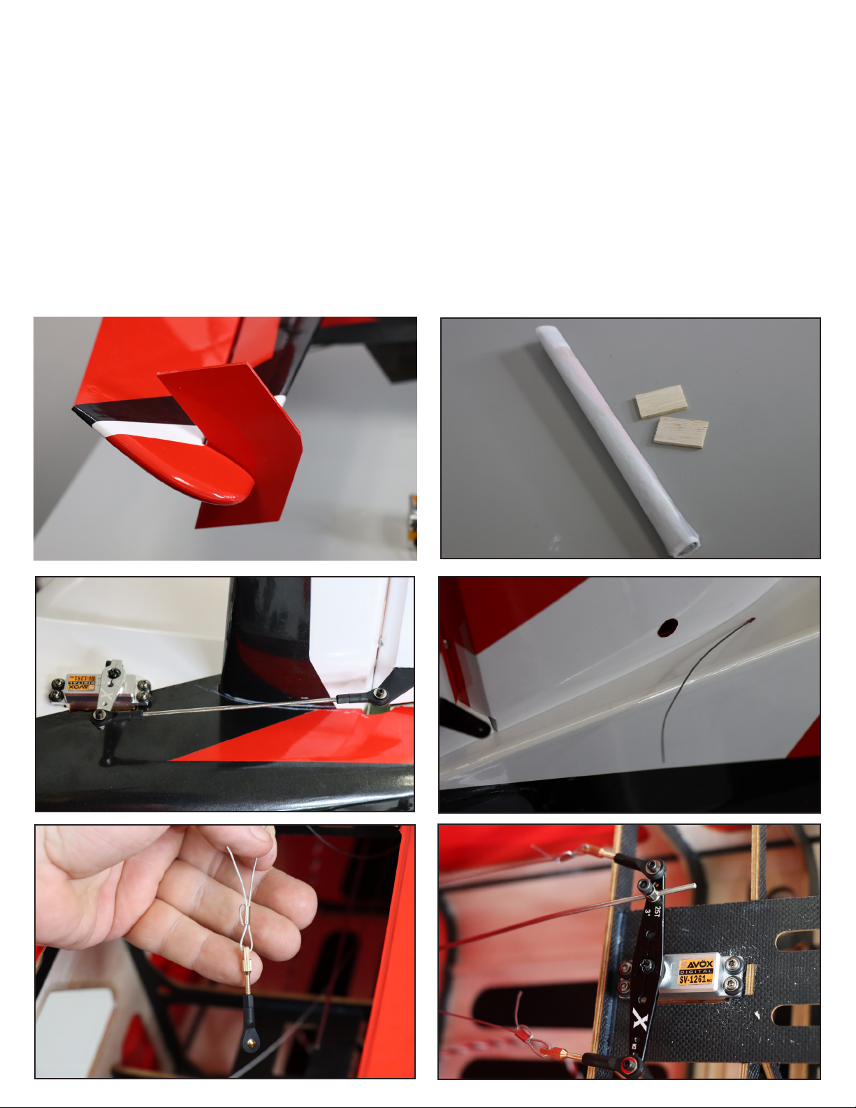
Using epoxy glue, mount the stab fences to the ends of the horizontal stabilizer as shown.
Optional Step: Included in your kit are two balsa pieces which can be used as llers by installing with
CA glue behind the elevator. To color match these panels, your kit includes spare covering sections,
also useful for small repairs.
Install the elevator servo as shown, running the extension for the servo through the fuselage and using
tape or a plastic clip to prevent the extensions from becoming unplugged in ight. read the rudder
cables through the slots on either side of the vertical stabilizer/rudder and into the fuselage as shown.
Run the cables forward, crossing them once to form an X shape inside the fuse. Assemble the cable
ends as shown, crimping the crimp tubes with pliers and adding a drop of thin CA. Install the rudder
servo, assembling the arm with cable ends and tailwheel pushrod as shown. Note that the tailwheel
pushrod connector should be le loose enough to rotate freely in the arm and a drop of medium CA
locks the nut in place.
Page 10
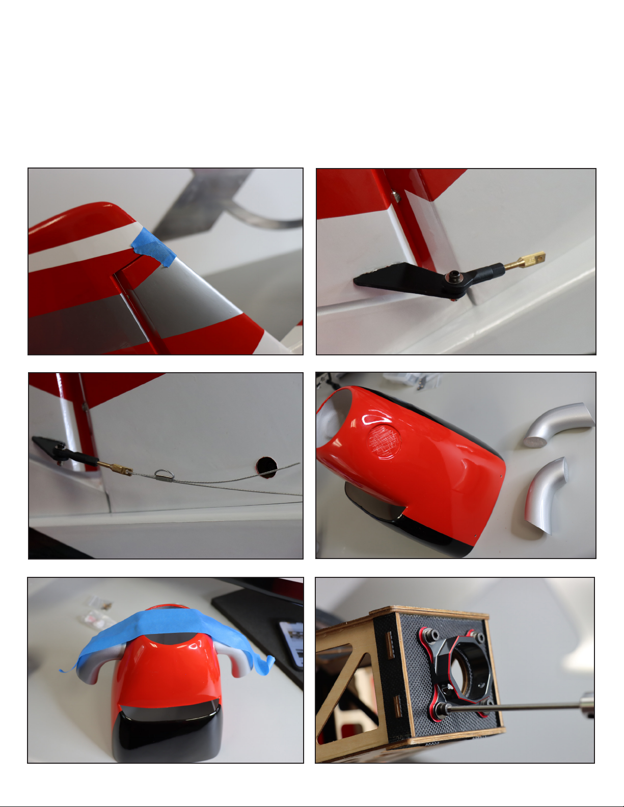
Tape the rudder as shown to hold it straight while you assemble the cables at the rear. Assemble
the cable ends as shown onto the rudder horns. Pull the cables taut and through the crimp tubes
and crimp as shown. Add a drop of thin CA to the crimp. read the cable ends into the ball links
to tighten the cables as needed. e goal is no sag and no play, but it’s not necessary to make them
“bajo string” tight.
Scu the recesses on the cowl, and the ends of the turbine exhaust pipes, and glue in place with
epoxy. Tape as necessary while the epoxy cures. Attach your brushless motor to the motor box with
loctite, here we are showing the installation of the recommended T-Motor AM600.
Page 11
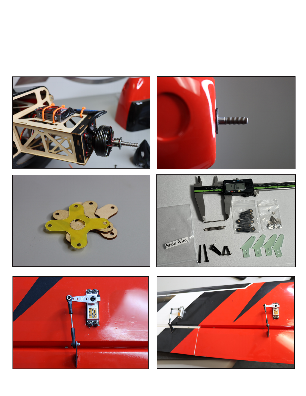
Mount your ESC as shown, tying all wires securely. Install the cowl and check the t of the prop
mount to make sure it extends a few mm beyond the front of the cowl. If you need extra motor
extension, your kit includes motor mount spacers as shown.
Locate the Main Wing hardware. Assemble the pushrods and install the control horns as you
did for the tail. Mount the servos into the wings, along with any extensions needed. Note the
orientation of the servos, arms, and pushrods.
Page 12
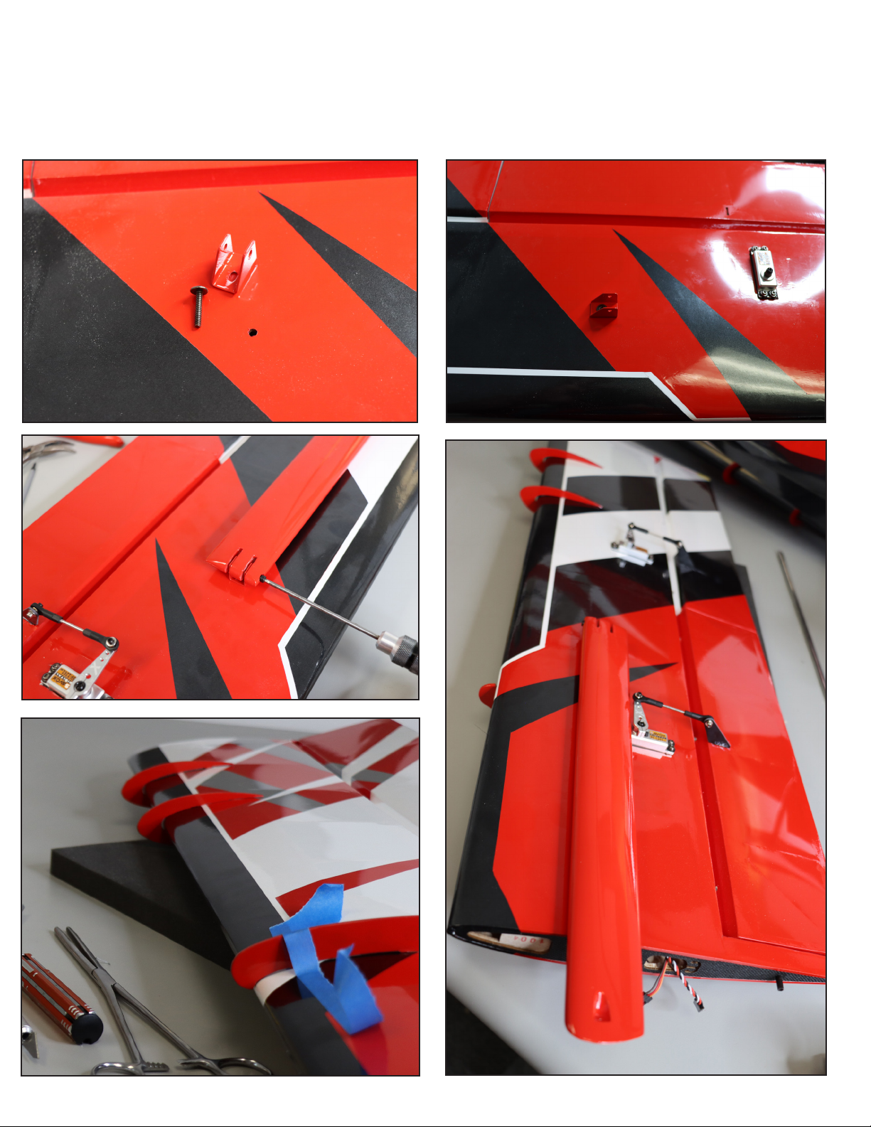
Locate the wing strut mounts and screws. Attach the strut mounts with loctite. Find the
correct (Right or Le side) strut and attach to the strut mount with the long screw. Lock the
screw with a drop of thin CA on the head. e strut is intended to fold against the wing as
shown for storage. Locate the wing fences and glue into the slots in the wing using epoxy.
Tape the fences in place as they dry. Clean up any excess glue with denatured alcohol.
Page 13
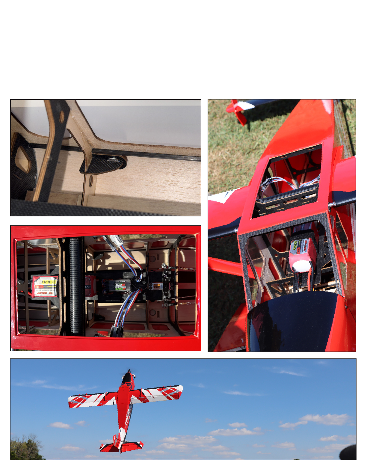
Locate the lower strut mount inside the fuselage. is is where the struts are mounted for ight
with a screw.
e balance point for the maiden ight of the Bushmaster is on the wing spar tube, you can easily
support the plane by the tube and it should hang level. Move your LiPo battery to adjust CG. Be
sure to use adhesive velcro on your battery and battery tray AND a velcro strap around the battery
and tray, to retain the battery in place.
For convenience in eld setup, we recommend the use of MPX dtwo-wire connectors (available at
ExtremeFlightRC.com) to connect the aileron and ap servo wires in the fuselage.
Page 14
Control settings:
Elevator: Low Rate 8-10 deg. 15-20% expo
3D Rate 45 deg. 60-70% expo
Aileron: Low Rate 15-20 deg. 20-30% expo
High Rate 38-40 deg. 60-70% expo (For best roll rate, mix aps to ailerons)
Rudder: Low Rate 20 deg 40-45% expo
High Rate 45 deg. 70-80% expo
Flaps: 40 degrees full deection with 5% down elevator mix at full deection
NOTE: Check rudder and elevator for interference at full deection.
Covering colors:
Oracover colors Ultracote colors
RED/WHITE Scheme
Ferrari Red #23 True Red-#HANU866
White #10 White-# HANU870
Silver # 91 Silver-#HANU881
Black #71 Black-#HANU874
BLUE/WHITE Scheme
#52 dark blue Midnight blue #HANU 885
White #10 White-# HANU870
Cub Yellow #30 Cub Yellow-#HANU884
Before ight, use a covering iron to go over all seams on the covering. Double check the
direction the controls move in and verify your prop is installed correctly. Check your power
system on the ground in a safe manner. Enjoy your Bushmaster!
 Loading...