

Page 1
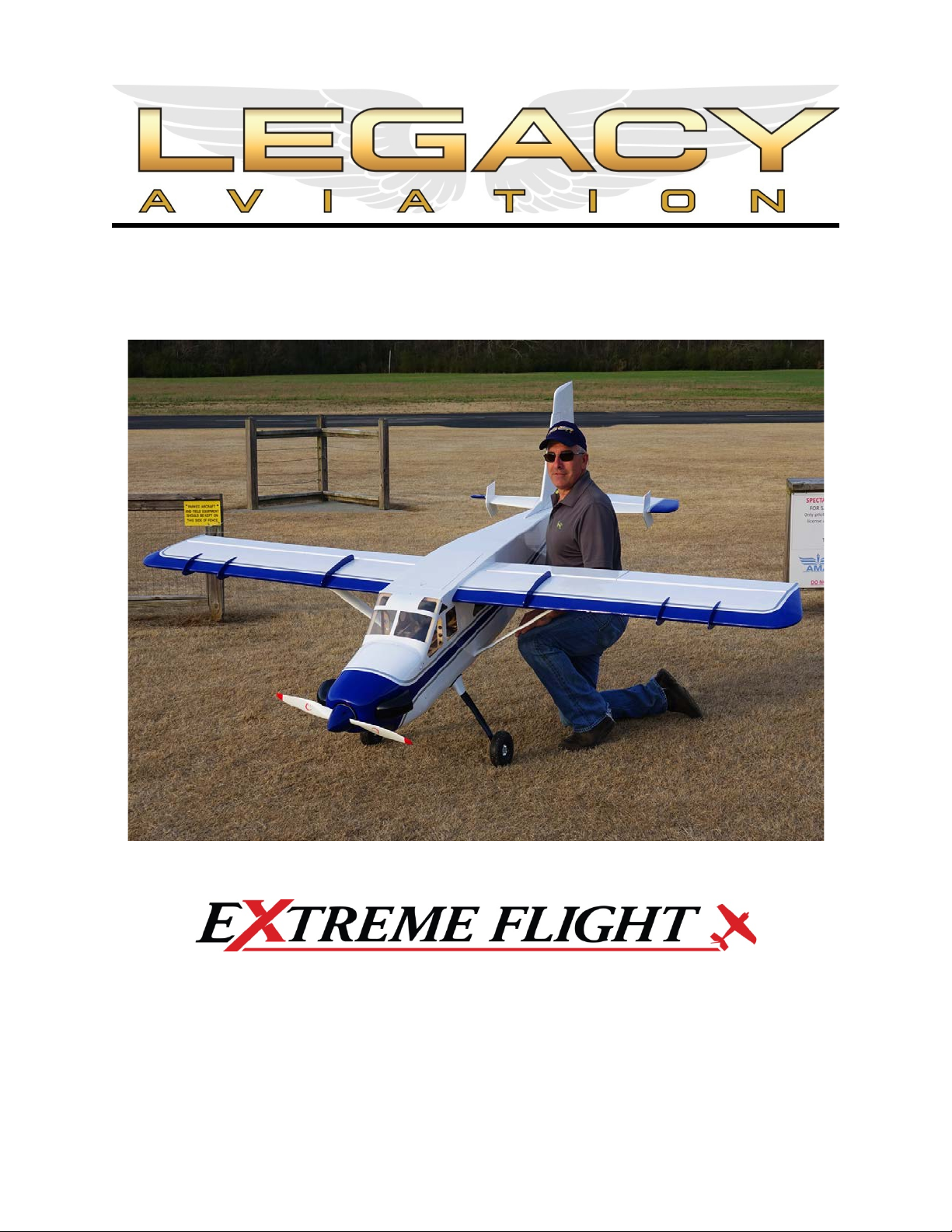
120”TurboBushmaster
Copyright2018ExtremeFlight
1
Page 2

Pleasetakeafewmomentstoreadthisinstructionmanualbeforebeginningassembly.We
haveoutlinedafast,clearandeasymethodtoassemblethisaircraftandfamiliarizing
yourselfwiththisprocesswillaidinaquick,easybuild.
Pleasereadthefollowingparagraphbeforebeginningassemblyofyouraircraft!
THISISNOTATOY!Seriousinjury,destructionofproperty,orevendeathmayresultfrom
themisuseofthisproduct.ExtremeFlightRCisprovidingyou,theconsumerwithaveryhigh
qualitymodelaircraftcomponentkit,fromwhichyou,theconsumer,willassembleaflying
model.Itisbeyondourcontroltomonitorthefinishedaircraftyouproduce.ExtremeFlight
RCwillinnowayacceptorassumeresponsibilityorliabilityfordamagesresultingfromthe
useofthisuserassembledproduct.ThisaircraftshouldbeflowninaccordancetotheAMA
safetycode.ItishighlyrecommendedthatyoujointheAcademyofModelAeronauticsin
ordertobeproperlyinsured,andtooperateyourmodelatAMAsanctionedflyingfields
only.IfyouarenotwillingtoacceptALLliabilityfortheuseofthisproduct,pleasereturnit
totheplaceofpurchaseimmediately.
ExtremeFlightRCguaranteesthiskittobefreeofdefectsinmaterialsandworkmanshipfor
aperiodof30DAYSfromthedateofpurchase.Allwarrantyclaimsmustbeaccompaniedby
theoriginaldatedreceipt.Thiswarrantyisextendedtotheoriginalpurchaseroftheaircraft
kitonly.
ExtremeFlightRCinnowaywarrantiesitsaircraftagainstflutter.Wehaveputtheseaircraft
throughthemostgruelingflighttestsimaginableandhavenotexperiencedanycontrol
surfaceflutter.Properservoselectionandlinkageset-upisabsolutelyessential.Inadequate
servosorimproperlinkagesetupmayresultinflutterandpossiblythecompletedestruction
ofyouraircraft.Ifyouarenotexperiencedinthistypeoflinkageset-uporhavequestions
regardingservochoices,pleasecontactusat[email protected]or770-887-1794.It
isyourresponsibilitytoensuretheairworthinessofyourmodel.
2
Page 3

ExtremeFlightandLegacyAviationareexcitedtoannouncethereleaseofthelongawaited
120"Bushmaster!ThebrainchildofCodyWojcik,thisdesignbuildsonthelegacyofthe
original84"and65"versionswhichhavebecomemusthaveadditionstothehangarsofRC
enthusiastsaroundtheglobe.Renownedforitsabilitytobebotha"relaxingbutnever
boring"sportmodelaswellasafullycapablebushstyleaerobat,theBushmasterdesignhas
wonlegionsoffanswhosimplywantagreatflyingmodelwithauniqueappearanceand
style.NowLegacyAviationdeliversthenextstepinthisseriesaimedatthegiantscale
enthusiast,the120"Bushmaster!DesignedaroundtheXpwr60brushlessoutrunnerand
theDA-70twincylindergasengine,theBushmasterdeliversaboutasmuchfunascanbe
hadwithanRCaircraftwitheitherchoiceofpowerplant.We'verecentlybeenflyingour
DA-70poweredversionwitha2into1headerandsinglecanistermufflersetupwhich
deliversquietconsistentpowerandlongflighttimes.OfcoursetheXpwr60versionwitha
12S5000+mahbatterysetupprovidesexcellentpowerandiscleanandquiet.Whichever
powersystemyouchoose,youarecertaintohaveamostfulfillingflyingexperience!
TheBushmasterfeaturesalightweightbuiltupbalsaandplywoodairframewith
strategicallyplacedcompositereinforcementstoaddstrengthandrigidity.Itfeaturesa
carbonfibermaingearandtailwheelassemblyalongwithcarbonfiberwing,staband
ruddermountingtubesandtwogorgeousUltracote(Oracover)colorschemes.Anexpertly
paintedfiberglasscowlisstandardfarealongwithaprolevelhardwarepackage.An
optionalfloatkitisalsoavailableforwaterbasedoperations.
Ultracote/OracoverColorCodes:
White/Blue/Silverscheme:UltracoteHANU870White,HANU885MidnightBlue,HANU881
Silver.Oracover21-010White,21-052DarkBlue,21-091Silver.
Yellow/Black/Greyscheme:UltracoteHANU872BrightYellow,HANU874Black,HANU882
LightGrey.Oracover21-033CadmiumYellow,21-071Black,21-011Grey.
3
Page 4

Recommendedaccessories:
DesertAircraftDA-70gasengineorXpwr60ccbrushlessoutrunner
MTWTD110Hrearexhaustcanisterwith60mmdrop,2-into-1headerandcouplerkit
24-34ounceFlowmastergastank
EFAnodizedfueldot
EFBluefuelline
52"EFservoarms(ailerons,flaps,rudder)
21.5"EFservoarms(elevators)
11"EFservoarm(throttle)
11.25"EFlightweightservoarm(tailwheelsteering)
BlazingStarDA-70mount
BlazingStarXXLStandoffsetforXpwr60
CastleCreations160HVESC
Falcon24x9carbonpropforDA-70
Xoar24x10or24x12woodorFalcon26x8carbonpropforXpwr60
Qty.2–EF6inch20AWGservoextension(Flaps)
Qty.3–EF24inch20AWGservoextension(Ailerons,throttle)
Qty.3-EF36inch20AWGservoextension(Elevators,tailwheelservo)
Qty.1–EF48inch20AWGservoextension(Rudder)
2setsEFMPXMulti-wireservoplug(2wireversion)
EFServoWireSafetyClips
4"EFCarbonFiberspinner
7hightorquemetalgearservosforcontrolsurfaces(MKS1220,MKS777A+orequivalent)
1highspeedservoforthrottle(MKS1250)
1metalgearminiservofortailwheelsteering(Hitec5245,7245)
4
Page 5
Let’sbegin!
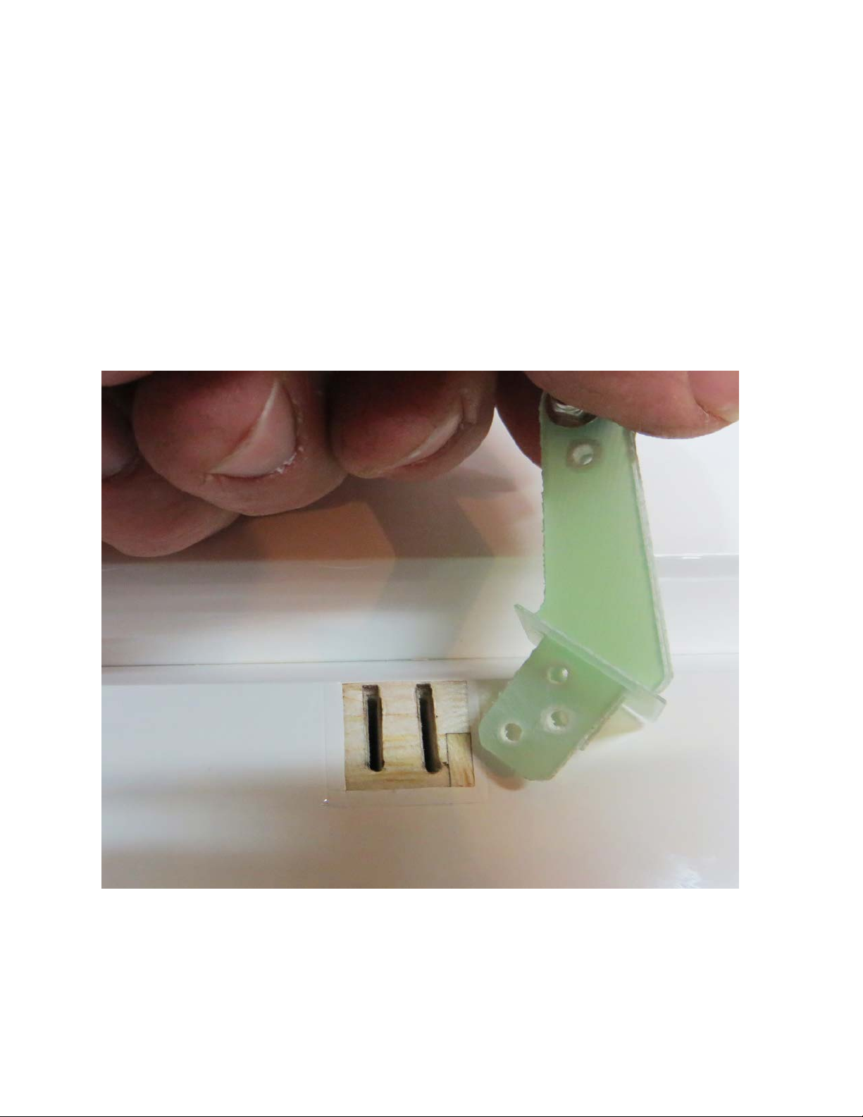
1.Locatethe2wingpanelsaswellastheG10aileronandflapcontrolhorns.Usesandpaper
toscufftheportionofthecontrolhornthatwillbegluedintothesurface.Foramore
finishedlookyoumaywishtopaintyourcontrolhornsbeforeinstallation.Donotpaintthe
portionofthecontrolhornthatwillglueintothecontrolsurface.
2.Usingasolderingironorasharphobbyknife,removethecoveringfromtheslotsforthe
aileronandflaphorns.Placethecontrolhornsintothebaseplate.Dryfitthehornsinto
theirrespectiveslotsandtrimanydebrisfromtheslotuntilthecontrolhornseatsproperly
againstthecontrolsurface.Sandawayanyportionofthebaseplatethatmayextend
beyondtheedgeofthebevel.Oncesatisfiedwithfitremovethecontrolhornsanduseyour
hobbyknifetoremovethecoveringthatisunderthebaseplateforbestglueadhesiontothe
surface.
5
Page 6
3.Applyagenerousportionof30-minuteepoxytotheaileronandflapcontrolhornslots
andtothescuffedareaofthecontrolhorns.Itmaybehelpfultouseaziptietopushthe
epoxyintotheslots.
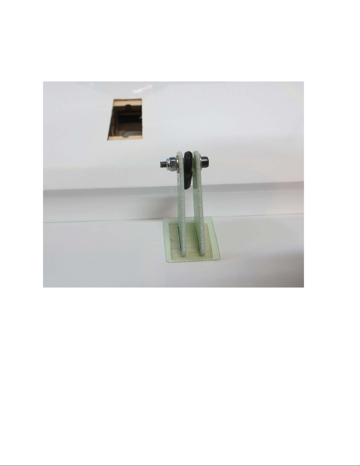
4.Assemblethecontrolhornsandballlinksasshownandinstallthecontrolhornsinto
theirrespectiveslots.Wipeawayanyexcessepoxywithapapertowelorclothsoaked
withdenaturedalcohol.
5.Inthesenextstepswewillinstallthehinges.Pleasetakeafewmomentstofamiliarize
yourselfwiththisprocessifyouhavenotinstalledhingepointsbefore.
Thereareseveralwaystodothisandseveraladhesivesyoucanuse.Wewilldescribethe
waythatwedoit,asthismethodhasprovenitselfovermanyyearsofmodelbuilding.If
youarenewtothistypeofhingingprocess,thenIrecommendthatyouinstallasingle
hingefirstjusttoacquaintyourselfwiththismethod
Beforestartingyouwillneedtogatherafewitemstoaidyouasyouproceed.
A. 30MinuteEpoxy
B. Ashortlengthofpushrodorsmalldowel.
C. Arollofpapertowels
D. DenaturedalcoholorAcetone
E. HobbyKnife
F. Teflonlubricant
6
Page 7
6.Locateawingpanelandseparatethecontrolsurfacesfromthemainwingandremove
thehinges.
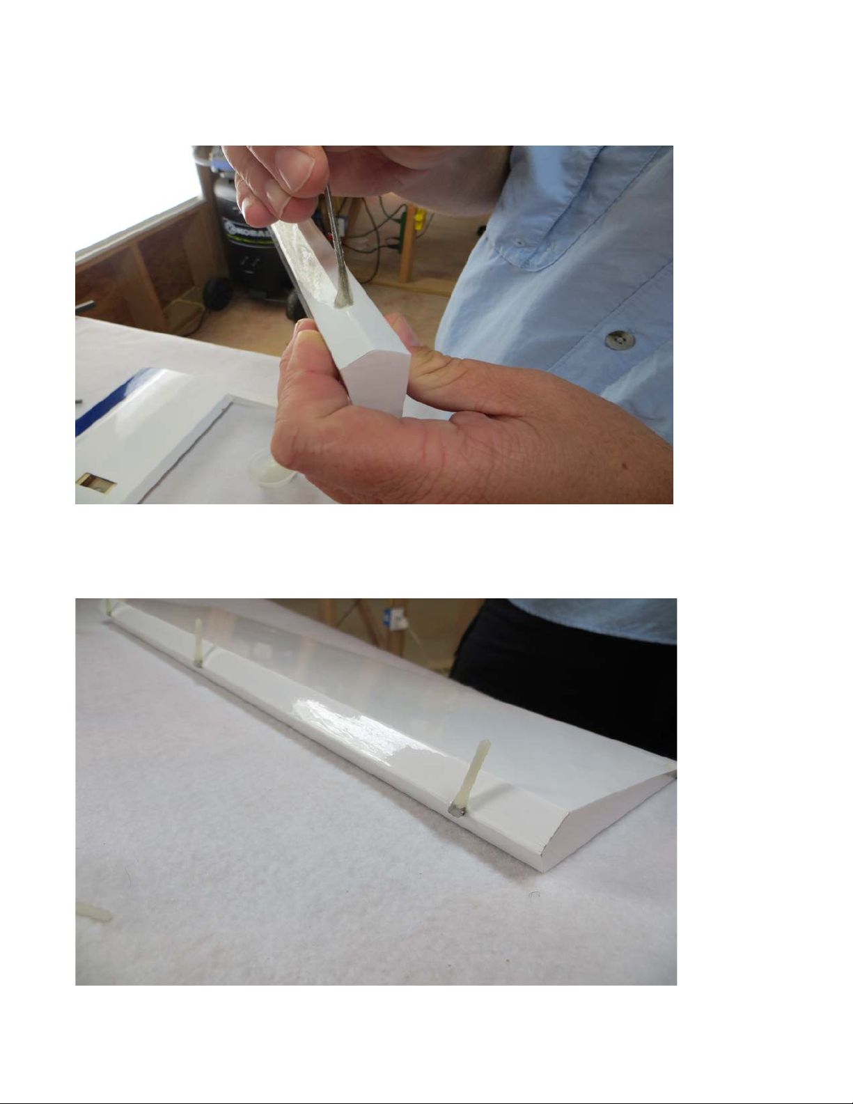
7.
Mixupagenerousbatchofepoxyanduseapieceofpushrodordoweltoapplythe
epoxytothehingehole.
8.Applyepoxytothebarbedsectionofthehingeononesideandinsertitintothehole
untilthecenterofthehingeiscenteredonthehingeline.Usingapapertowelsoaked
withacetoneordenaturedalcoholwipeawayanyepoxythathasbeensqueezedoutof
thehole.
7
Page 8
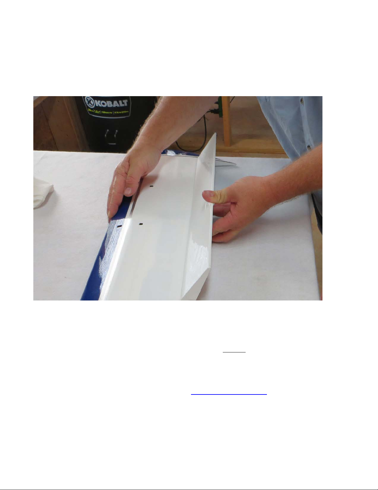
9.Makesurethehingecanmovefreelyandthatthepinisalignedproperlybeforethe
epoxysets!Whenyouaresatisfiedwiththeresultssetthesurfaceasidesothatthe
epoxywillpoolaroundtherearofthehinge.Whenyouarecomfortablewiththis
processyoushouldbeabletodoonesideofasurfaceperbatchofepoxy.Repeatthe
processtoattachthesurfacestoeachwing.Thereshouldbeaslittlegapaspossible
whilestillallowingmaximummovementofthecontrolsurface.
10.Asafinalstepbeforesettingthewingasidetodry,doafinalcleaningofthehinge
knuckleswithapapertowelsoakedwithdenaturedalcoholoracetonetoremoveany
epoxyresidue.Ifyoufindanyofthehingesarestiffafterdrying,applyadropofacetone
toeachhingewithaQ-tipandmovethesurfacebackandforthseveraltimestoloosenit
up.AsafinalstepItypicallyapplyacoupledropsofTeflonlubricanttoeachhinge.This
isavailableatmosthomeimprovementandhardwarestores.
11.Youwillneedtoattacha24inchservoextensiontoyouraileronservotoreachthe
wingroot.Theflapservowirewillrequirea6inchextension.Securetheextensionsto
theservoleadswithheatshrinktubingoraservowiresafetyclip.
8
Page 9
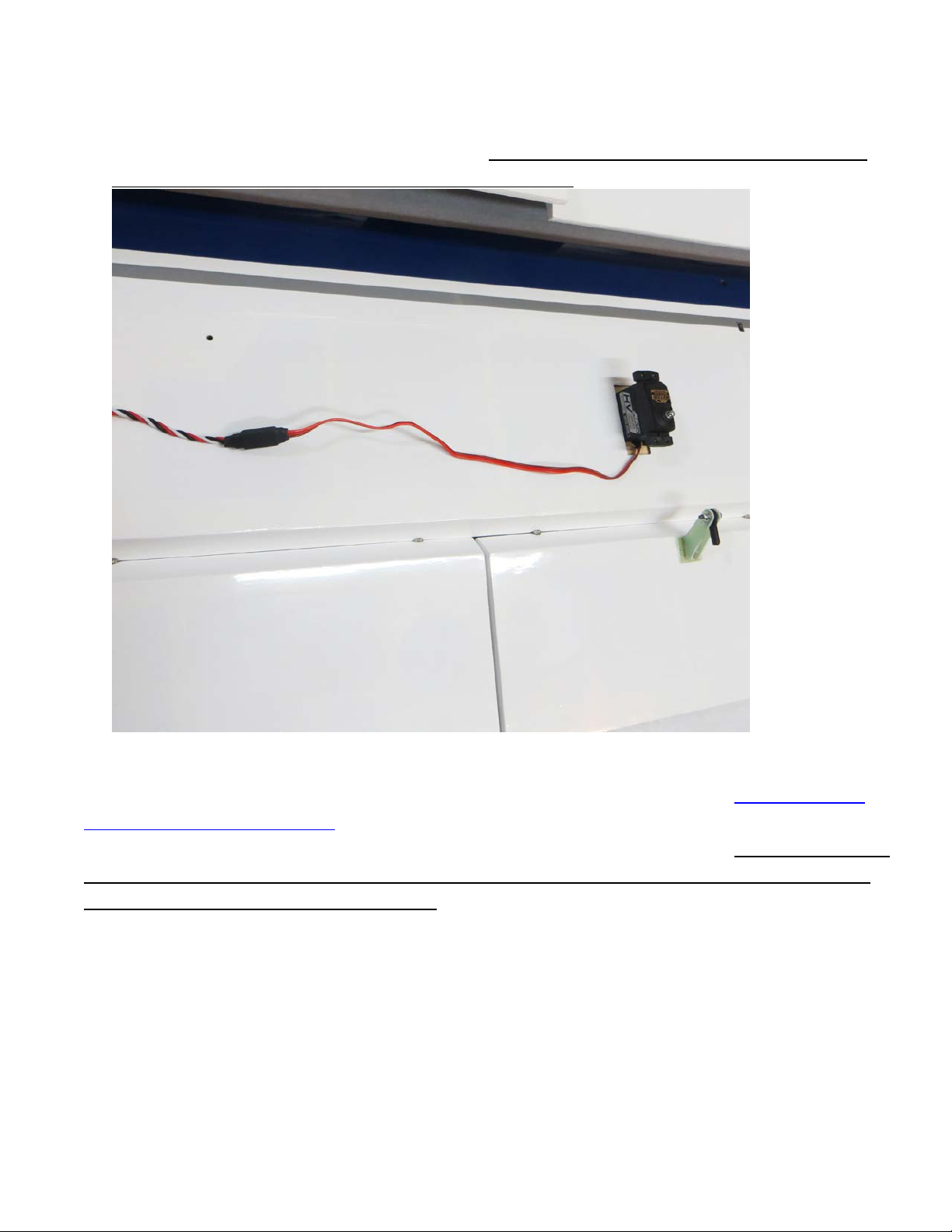
12.Usethemanufacturersuppliedmountinghardwaretoinstallthewingservoswith
theoutputshafttowardtheTRAILINGEDGEofthewing.Electronicallycenterthe
servoandinstall2inchservoarmsontotheservospline.Theservoarmsshouldbe
paralleltothehingelinewhencentered.Itisveryimportantthatyouusethesame
lengthservoarmsforbothflapandaileronservos.
13.Foreaseoffieldassemblywehighlyrecommendusing2setsoftheExtremeFlight
MPXMulti-wireservoplugs.Attachthesetotheservoextensionsprotrudingfromthe
wingforafastandeasysingleplugsolutiontowingservoconnections.Besuretosecure
theMPXplugleadsothatitcannotfloparoundinsideofthewing,possiblycausingthe
plugtopulloutofthereceivingsocket.
9
Page 10
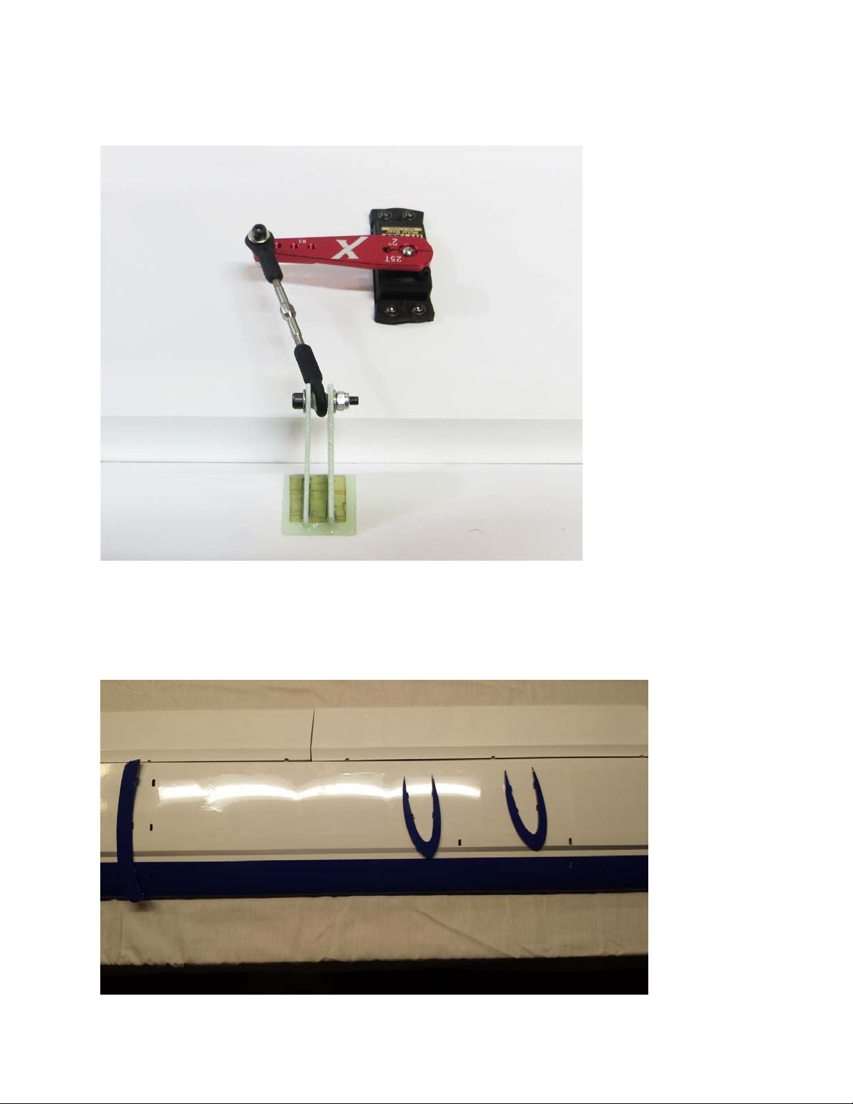
14.Usethesuppliedballlinks,turnbucklepushrods,3mmbolts,washersandnutsto
assembletheaileronandflaplinkagesandsecuretotheservoarmandcontrolhorns
asillustratedinthefollowingphoto.Boththeaileronandflaplinkageareassembled
thesameway.
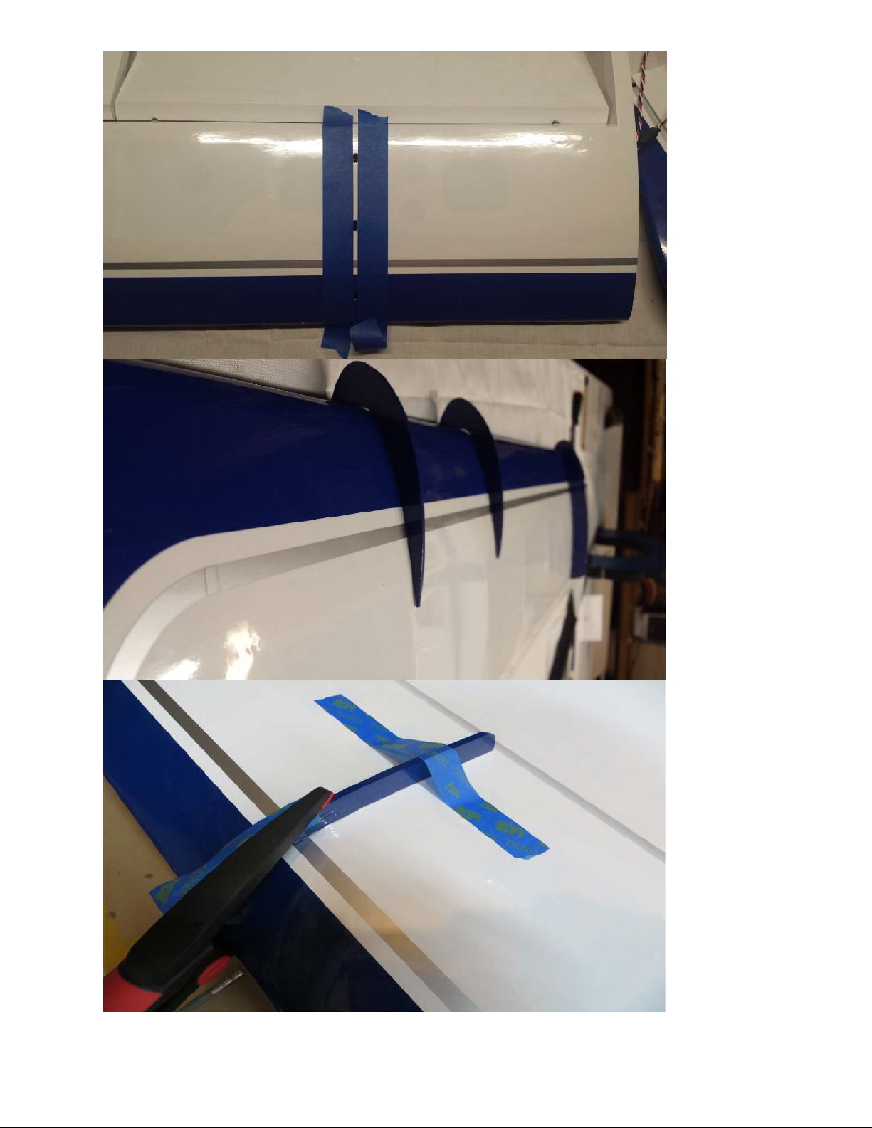
15.Locatethewingfencesandtrialfitontothewing.Somesandingmayberequired
forbestfit.Werecommendgluingthefencesinplacewithepoxy.Usetapeorclamps
toholdthefencesinplacewhiletheepoxycuresmakingsuretheyareperpendicular
tothesurfaceofthewing.Twostripsoftapeplacedparalleltothefenceswillkeep
excessepoxyfromgettingonthewingsurface.
10
Page 11
11
Page 12
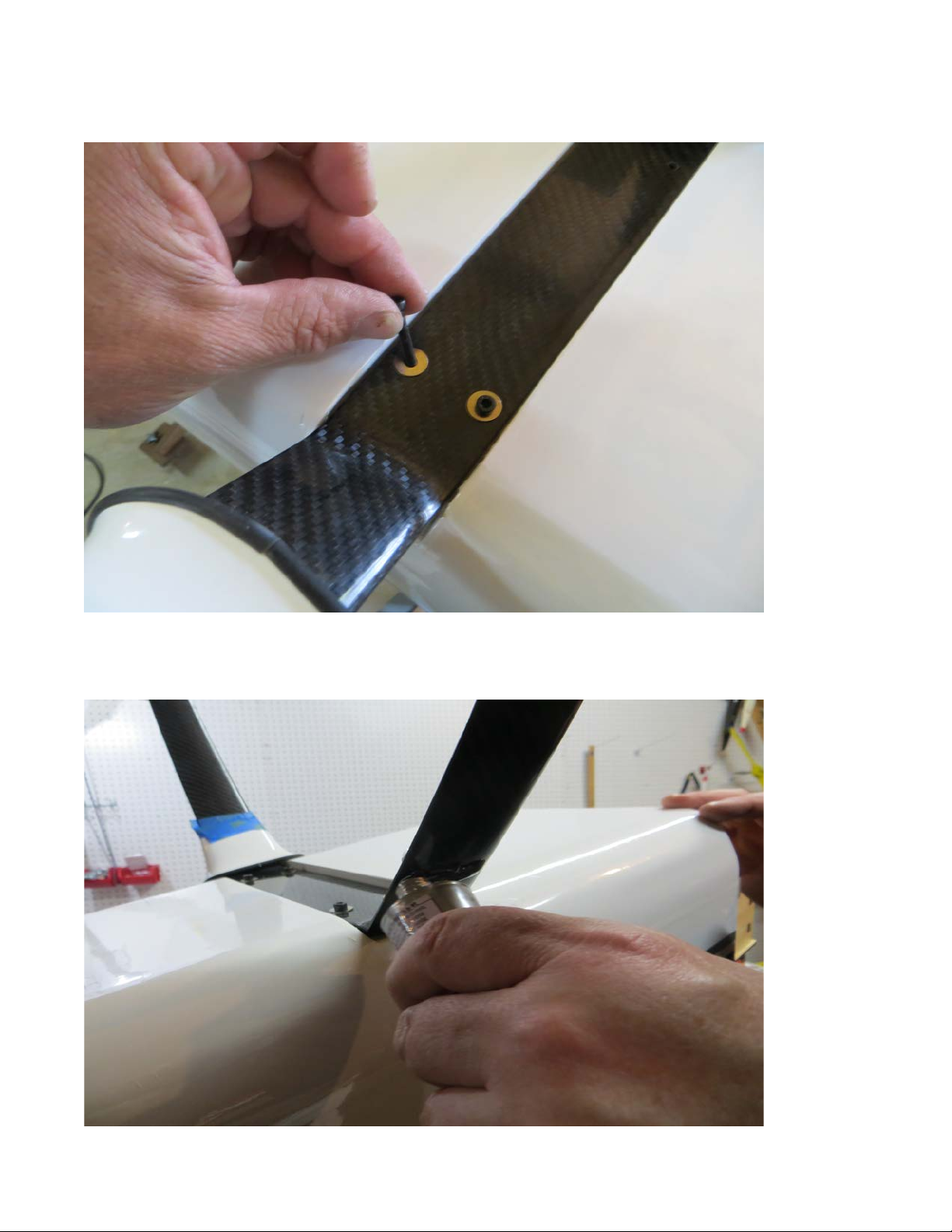
16.Locatethelandinggearcomponentsandtheassociatedfastenerpackageformthe
hardwarekit.Securethecarbonfiberlandinggeartothefuselagewiththeprovided
4mmsocketheadcapbolts,washersandlocknuts.
17.ApplyabeadofGoopadhesivetothecarbongearandslidethelandinggearfairing
intopositionagainstthebottomofthefuselage.Securewithtapeuntiltheadhesive
dries.
12
Page 13
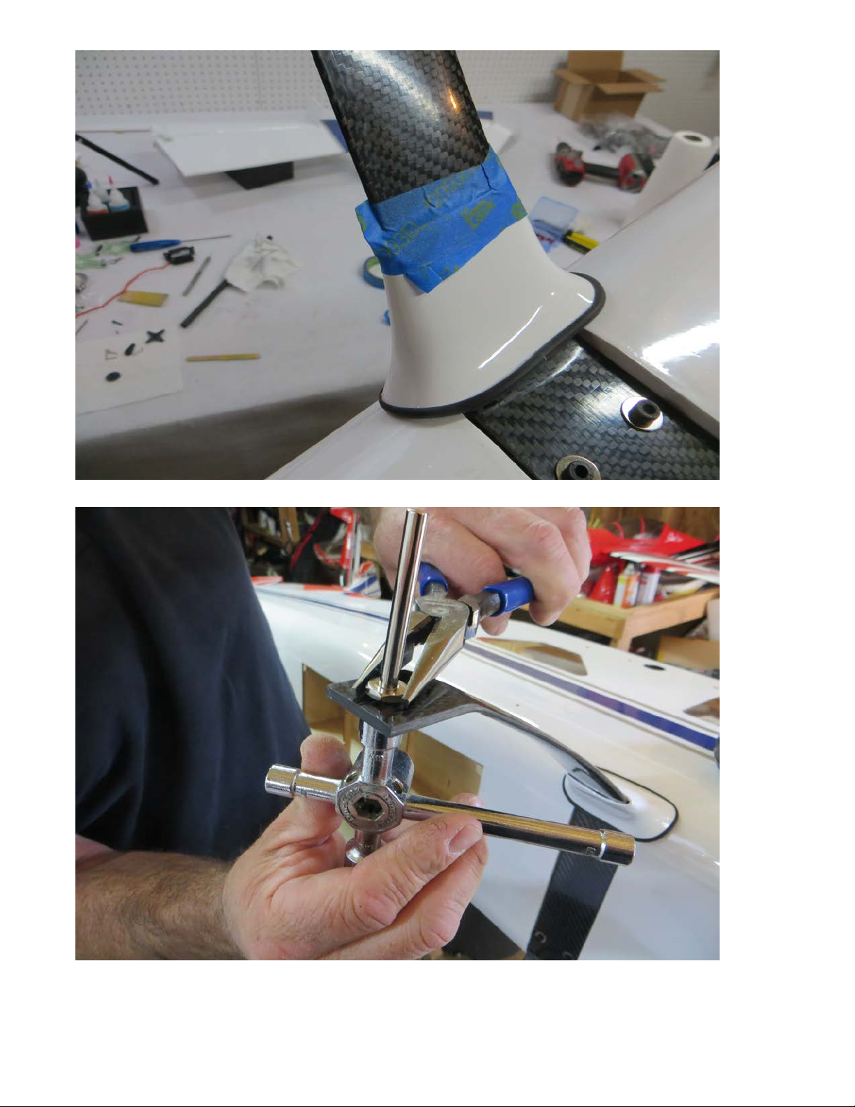
18.Attachtheaxlestothecarbongearwiththesuppliedwasherandlocknut.
13
Page 14
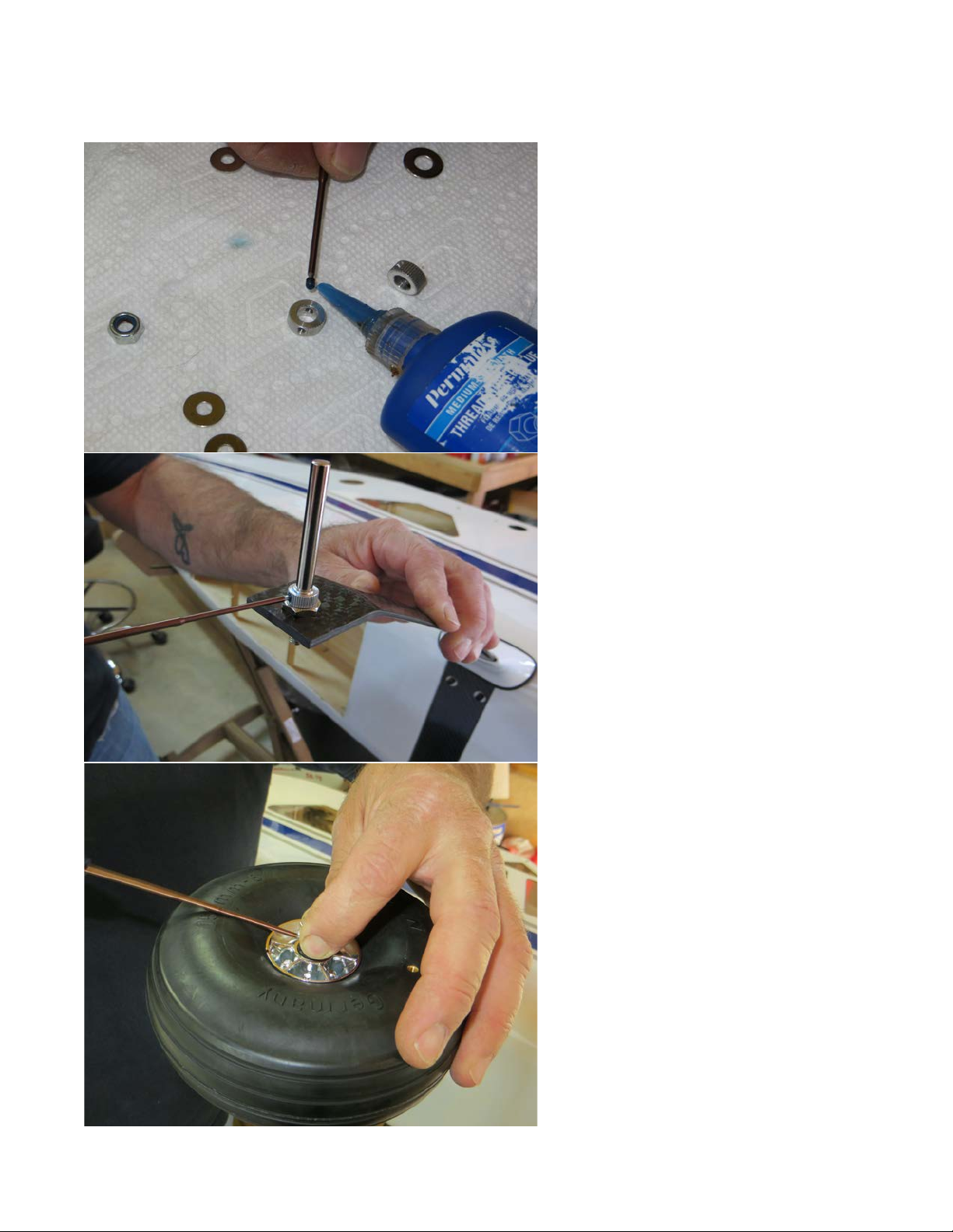
19.Fileaflatspotontheaxlesforthewheelcollarsetscrewstoseatagainst.Securethe
wheelintopositionwithacollarplacedoneachside.BesuretouseLoctiteonall
fasteners!
14
Page 15
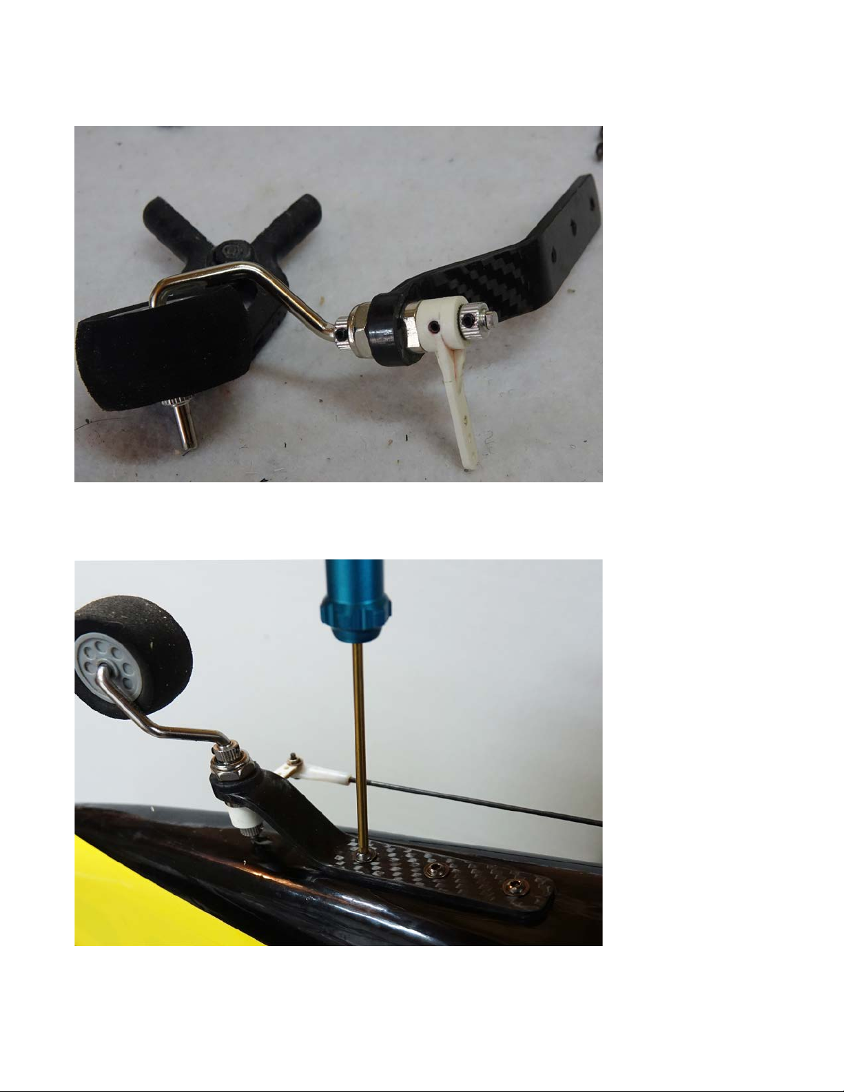
20.Assemblethetailwheelasshown.Itishighlyrecommendedthatyouflieaflatspot
atthelocationthateachsetscrewwillseatandagain,applybluethreadlockcompound
toallscrews.
21.Installthetailwheelassemblyontothebottomrearofthefuselagewiththeprovided
3mmboltsincludedinthehardwarepackage.Thisstepwillallowustoturnthefuselage
overandplaceitonits"feet"whichwillallowabetterpositiontoinstalltheengine.
15
Page 16
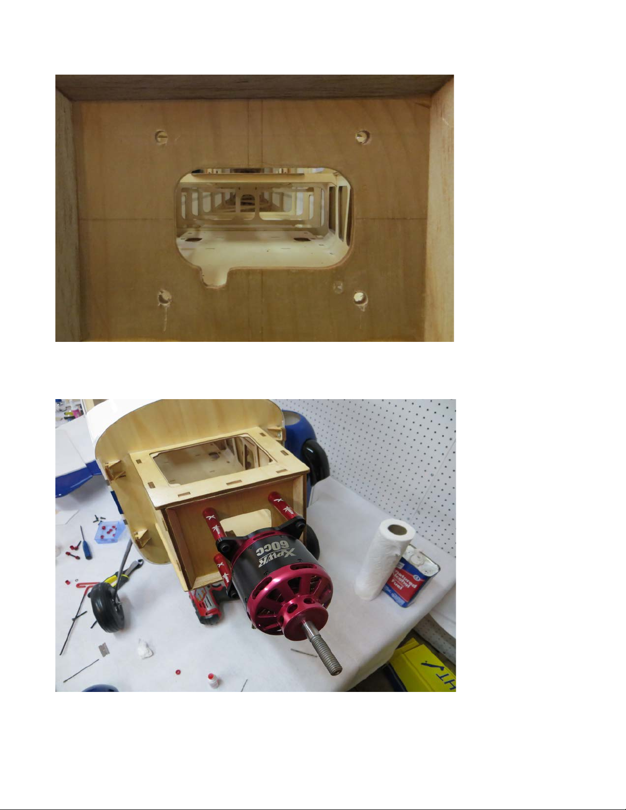
22.Flipthefuselageandletsinstallourpowerplantofchoice.Drill41/4"holesatthe
designatedlocationforyourmotor/engine.
23.IfusingtheXpwr60itishighlyrecommendthatyouusetheBlazingStarXXLStandoff
Settoachieveproperspacingwithminimalhassle.IfusingtheDA-70theBlazingStar
mountmakesproperenginepositioningabreeze!
16
Page 17
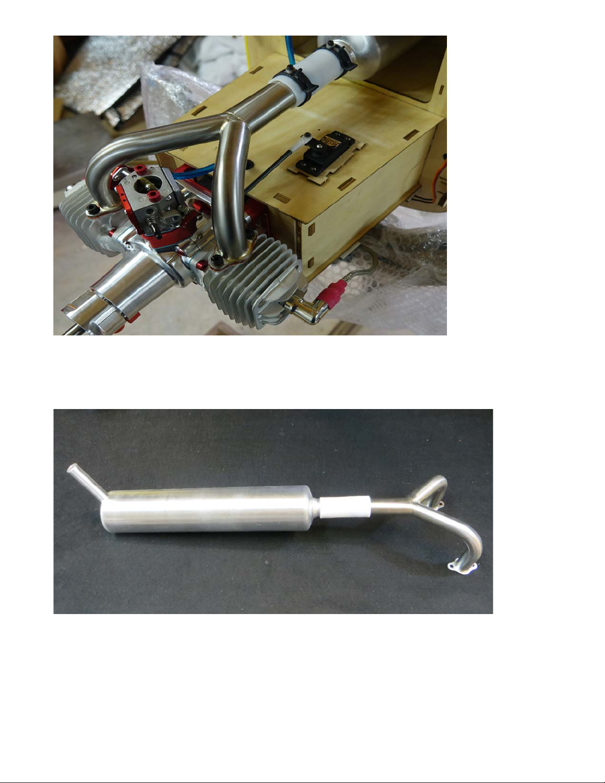
24.Inthepreviousphotoyoucanalsoclearlyseetheinstallationofthe2-into-1
header/canistersetupandthethrottleservoinstallation.Hereareafewmorepicsofthe
enginesetupincludingtheignitionmountinglocationandthecoolingcutoutsonthe
bottomofthecowl.
17
Page 18
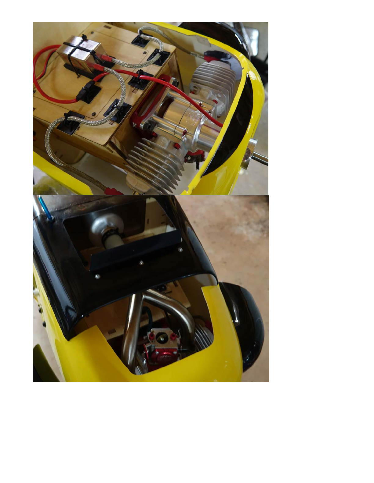
25.TheBushmastercowl,becauseitlacksanyairinlets,requiressomecreativecooling
methodstokeepourpowersystemrunningproperly.Inthepreviousphotoyoucansee
thecutoutswemadeinadditiontotheairdamweinstalledtopullairovertheengine
andoutofthecowl.Thiswasfabricatedfromapieceofaluminumflashingpurchased
fromalocalhomeimprovementstore.Properventilationisamust!!!!
18
Page 19
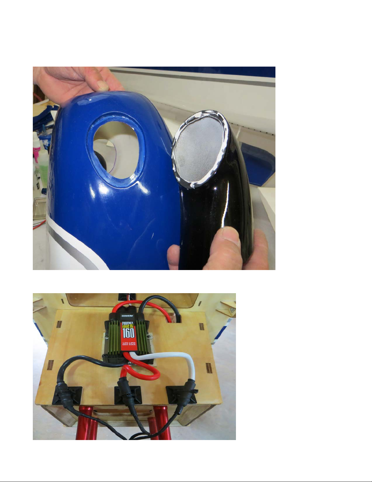
26.Inadditiontoopeningupthebottomofthecowlwealsomadesurethedummy
exhauststackscontributedtopullingairoverthecylindersandremovingitfromthecowl
byopeningthecowlandexhauststacksbeforegluinginplace.Removeasmuchpaintas
possiblefromthegluingsurfaceaspossibleandglueinplacewith30minuteepoxy.
27.Beforefinalinstallationofthecowlanddependingonyourchoiceofpowersystem
installeitheryourgastankonthetank/batterytraywithplumbingortheESC.
19
Page 20
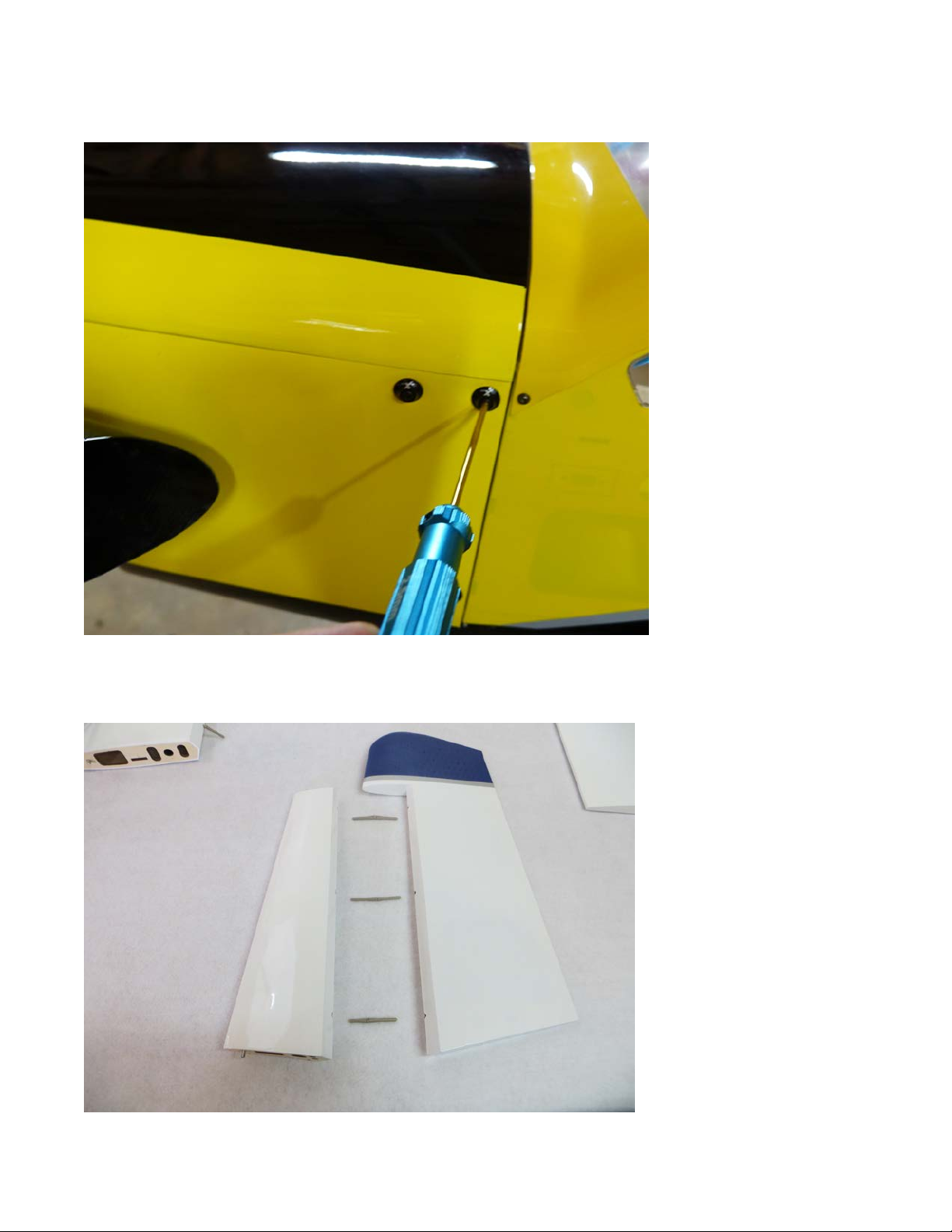
28.Installthelowercowlhalf,withthe43mmboltsprovidedinthehardwarepackage,
followedbythetoppieceofthecowlwith4more3mmbolts.Inthisphotowehave
addedtheEFanodizedwashersforatouchofbling.
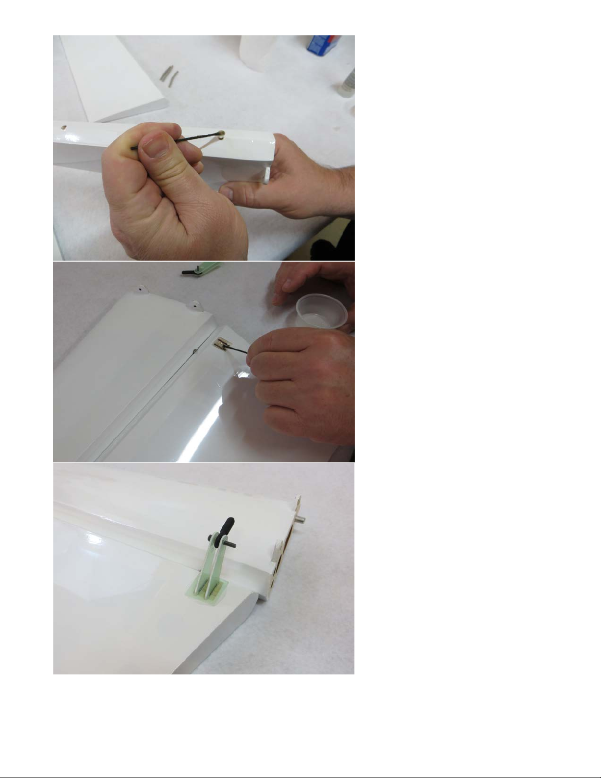
29.Locatethestab/elevatorsetalongwiththeelevatorcontrolhorns.Usingthesame
methodastheailerons,hingebothstabhalvesandinstallthecontrolhornsinthe
locationshown.
20
Page 21
21
Page 22
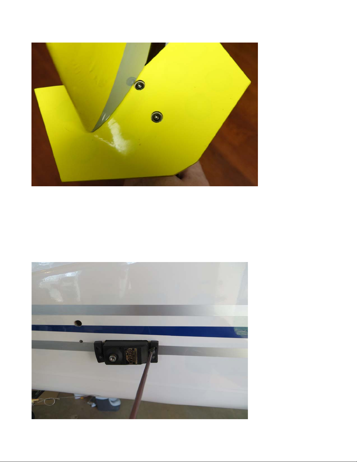
30.Installtheelevatorfenceswiththeprovided3mmboltsinsertedthroughthefence
andintothepre-installedblindnutsinthestab.
31.Slidethecarbonfiberstabtubeintothesleeveinthefuselagerear,thenslideboth
stabsontothetubeandsecurewith23mmboltsandwashersinsertedthroughthetabs
atthestabrootandintotheblindnutspre-installedinthefuselage.Besuretouse
threadlockonallbolts.
32.Installyourelevatorservosintheprovedlocationandassemblethelinkageasshown
inthefollowingpictures.
22
Page 23
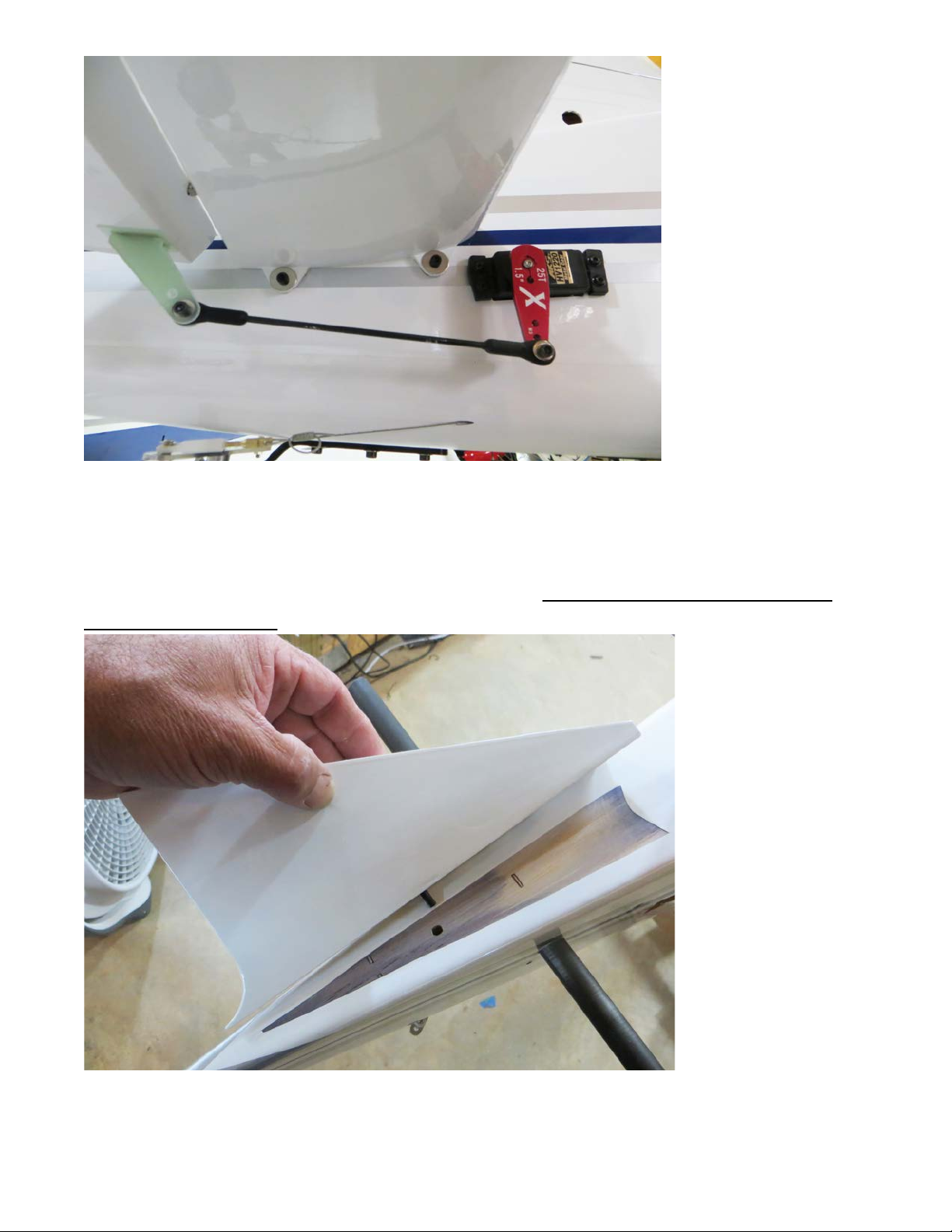
33.Placetherudderfairingblockintopositionandtracearounditwithafinetippedfelt
marker.Useasharphobbyknifetoremovethecoveringasshownforawoodtowood
bondandglueinplacewithmediumCAorepoxy.Besuretocheckalignmentwith
rudderbeforegluing!
23
Page 24
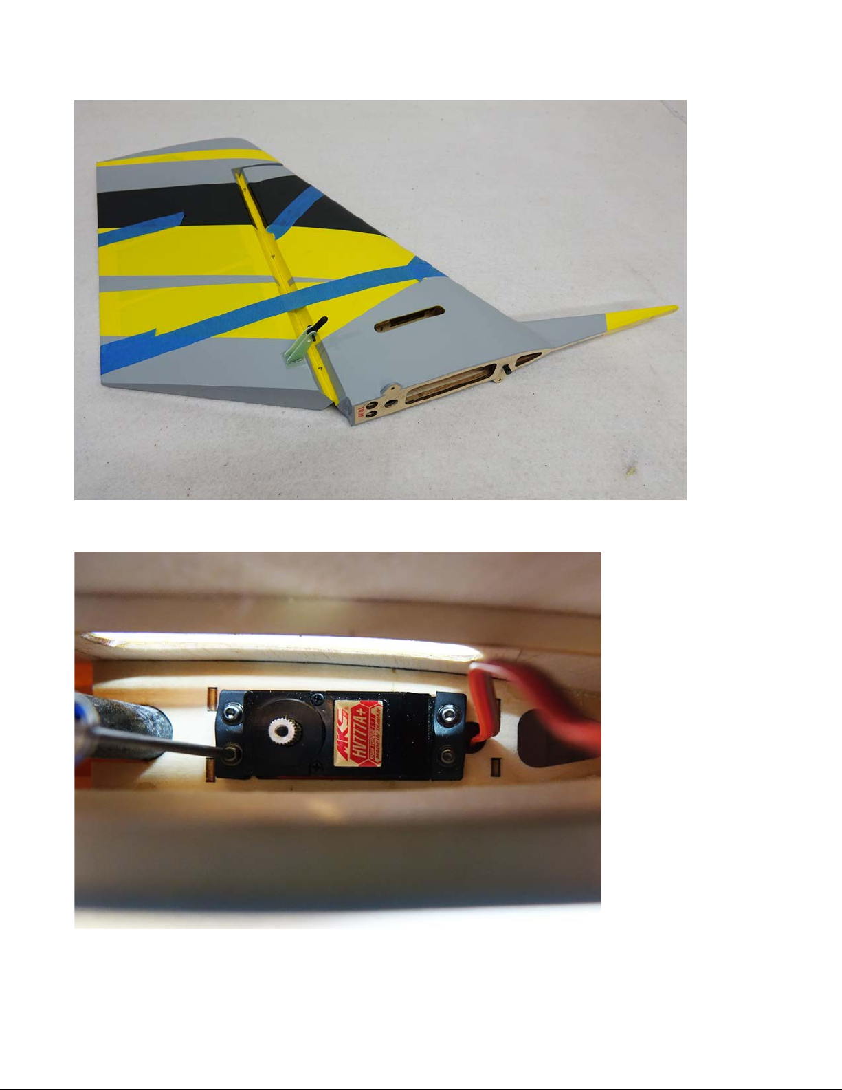
34.Usingthesamemethodaswiththeaileronsandelevators,gluetherudderhinges
andruddercontrolhornsinplacewith30minuteepoxy.
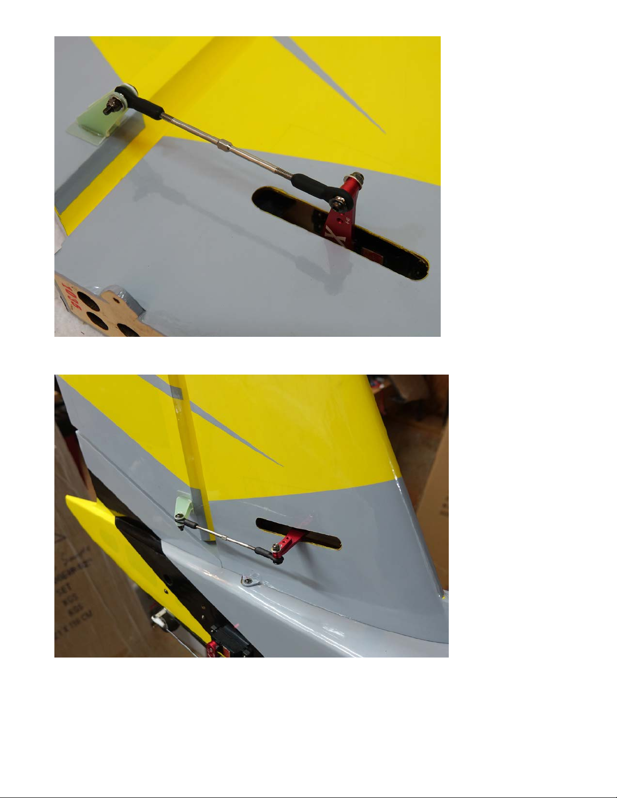
35.Installtherudderservointhedesignatedlocationinsidetheverticalfinwiththe
outputsplineorientedtowardtherearofthemodelandassemblethelinkageasshown.
24
Page 25
36.Slidethecarbonfiberruddermountingtubeintothereceptacleinthefuselage.Slide
therudderintopositionandsecurewith23mmboltsandwashers.
25
Page 26
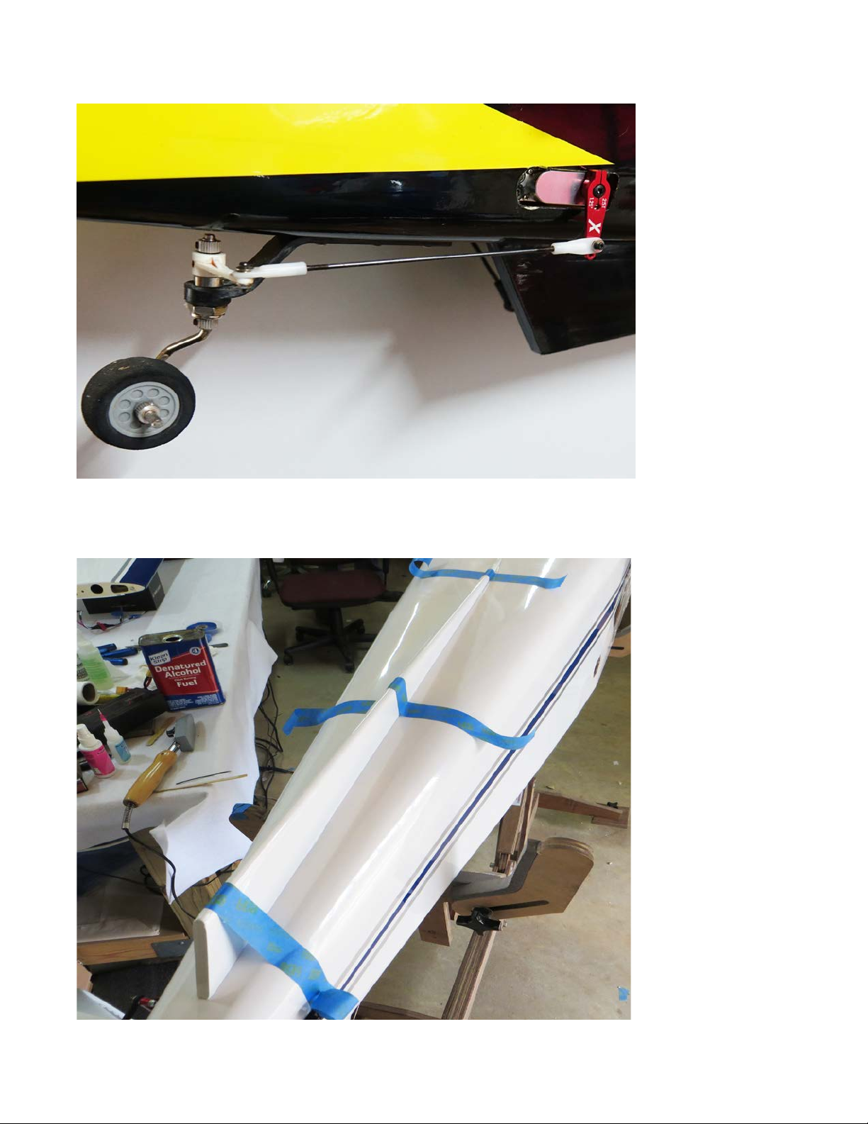
37.Installthetailwheelsteeringservointoitsdesignatedlocationandassemblethe
linkageasshown.
38.Ifyouareplanningtoinstallthefloatkitandflyfromwaterinstallthekeelonthe
bottomofthefuselage.Glueinplacewithepoxymakingsureitisperpendiculartothe
bottomofthefuselage.Usetapetokeepitproperlypositioneduntilthegluedries.
26
Page 27

39.Insertthecarbonfibermainwingtubeintothesleeveinthefuselage.Slidethe
wingsintopositiontakingcaretoinserttheservoextensionsintothefuselage.Secure
thewingsbyinsertingthenylonwingboltsintotheholesinthefuselageandthreading
themintotheblindnutinthewingroot.
40.Attachthewingstrutsusingthesupplied3mmcapheadboltsinsertedthroughthe
holesineachendofthestrutsandintotheattachmentpointsinthewingandfuselage.
Youmayfinditeasiesttostartwiththewingattachmentfirst.Don'tfullytightenuntil
bothboltsareinsertedintothepre-installedblindnuts.
Thisconcludestheassemblyprocessforthe120"TurboBushmaster.
Preparingforflight!
Withthewingandstrutsattached,placeyourbatteriesinthemodelandpickupthe
Bushmasterbythewingtube.Shiftthebatteriesuntiltheplanebalancesonthetube,
thensecurethebatterieswithvelcro.Thisisasafelocationtobegintestflying.Itis
recommendyou firstfly themodelinstandardconfiguration togetusedtoitsflight
characteristicsbeforebeginningtoexperimentwithflaps.Whendeployingflapsyou
willneedto addanelevator mixthat compensatesforthe flapsand providesafew
degreesofdownelevator.
ThankssomuchforyourbusinessandwehopeyouenjoyflyingyourTurboBushmaster
asmuchaswehave!
27
 Loading...