

Page 1
T URBO
A V I A T I O NA V I A T I O N
DESIGNED BY
CODY WOJCICK
Copyright 2023 Extreme Flight RC
BY
Page 2
Please take a few moments to read this instruction manual before beginning assembly. We have outlined a
fast, clear and easy method to assemble this aircraft and familiarizing yourself with this process will aid in a
quick, easy build.
Please read the following paragraph before beginning assembly of your aircraft!
THIS IS NOT A TOY! Serious injury, destruction of property, or even death may result from the misuse of this product. Extreme
Flight RC is providing you, the consumer with a very high quality model aircraft component kit, from which you, the consumer,
will assemble a flying model. It is beyond our control to monitor the finished aircraft you produce. Extreme Flight RC will in no
way accept or assume responsibility or liability for damages resulting from the use of this user assembled product. This aircraft
should be flown in accordance to the AMA safety code. It is highly recommended that you join the Academy of Model Aeronautics in order to be properly insured, and to operate your model at AMA sanctioned flying fields only. If you are not willing to
accept ALL liability for the use of this product, please return it to the place of purchase immediately.
Extreme Flight RC, Ltd. guarantees this kit to be free of defects in materials and workmanship for a period of 30 DAYS from the
date of purchase. All warranty claims must be accompanied by the original dated receipt. This warranty is extended to the original purchaser of the aircraft kit only.
Extreme Flight RC in no way warranties its aircraft against flutter. We have put these aircraft through the most grueling flight
tests imaginable and have not experienced any control surface flutter. Proper servo selection and linkage set-up is absolutely essential. Inadequate servos or improper linkage set up may result in flutter and possibly the complete destruction of your aircraft.
If you are not experienced in this type of linkage set-up or have questions regarding servo choices, please contact us at info@
extremeflightrc.com or 770-887-1794. It is your responsibility to ensure the airworthiness of your model.
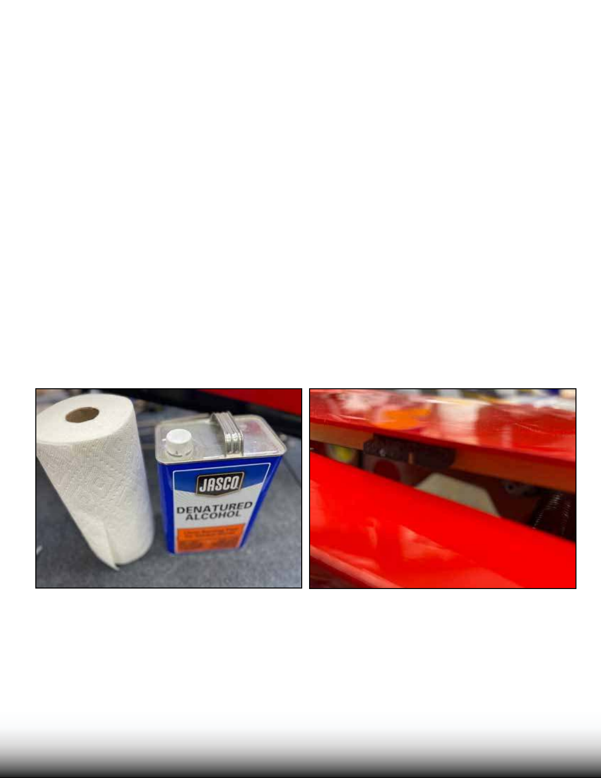
Two points to start: In this build, we will use epoxy glue in several steps. Prompt cleanup of any excess
epoxy is important. We recommend you use denatured alcohol, available at most hardware and home-improvement stores.
When you unpack your airplane, note that in order to remove the main hatch, you must release the latch
and then *pull forward* to release the hatch.
TURBO
B BUUSHSHMMAASSTTERER
Page 3
1978
594
550
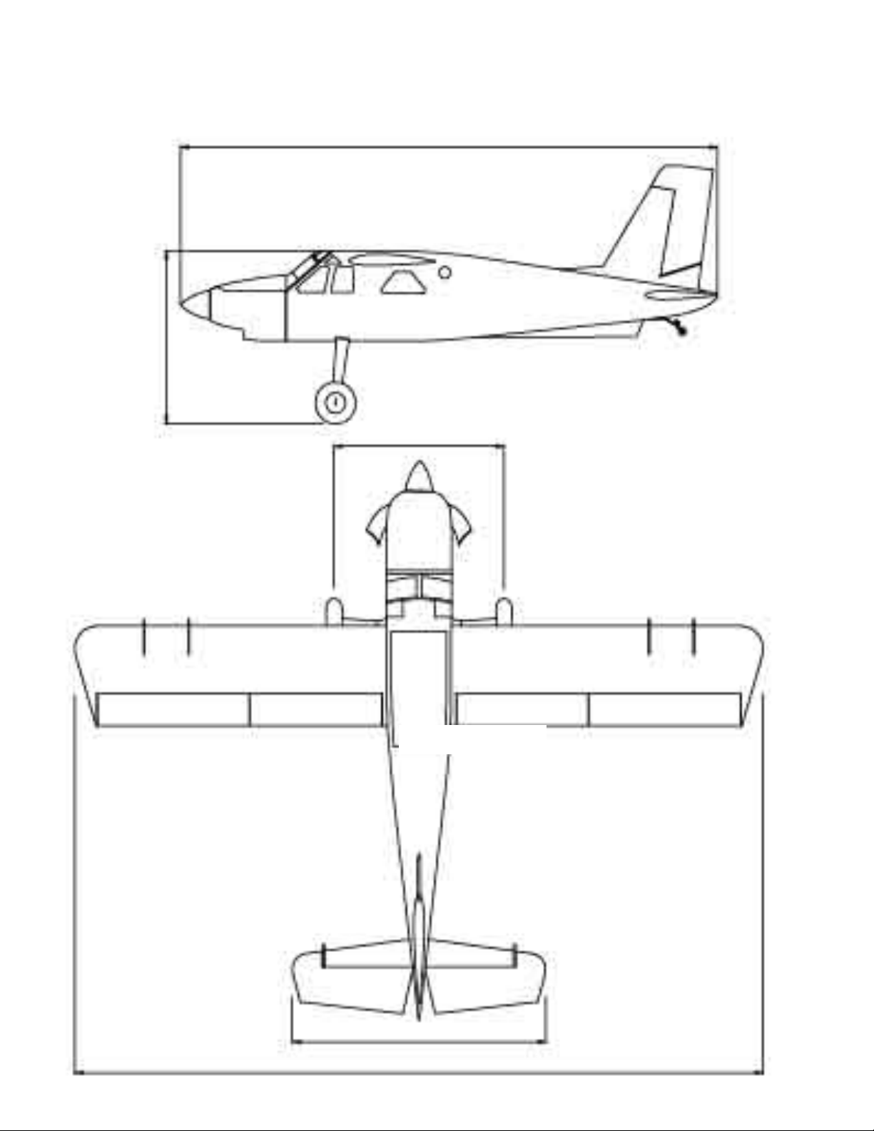
Bushmaster 100in.
Fuselage Length: 1978mm/77.9 in.
Wing Span: 2540mm
WING AREA: 79dm²/1224.5 sq.in.
Wing tube:22x965mm/6x320mm
Stab tube:13x360mm/6x160mm
Main wing incidence:0.5 deg
Stab incidence:0 deg
Right thrust:2 deg
Up/Down thrust:0 deg
/100 in.
935
2540
Page 4

WingSpan: 100” Spinner: 3.5”
Length: 78” Weight: 16 lbs (elec, no lipo)
Wing area: 1224 sq. in.
Center of Gravity Range (Measured from wing leading edge at root): 3.3-4.25 “ (89-108mm)
Our preferred CG is center of the wing tube.
Control settings:
Elevator: Low Rate 8-10 deg. 15-20% expo
3D Rate 45 deg. 60-70% expo
Aileron: Low Rate 15-20 deg. 20-30% expo
High Rate 38-40 deg. 60-70% expo (For best roll rate, mix aps to ailerons)
Rudder: Low Rate 20 deg 40-45% expo
High Rate 45 deg. 70-80% expo
Flaps: 40 degrees full deection with 5% down elevator mix at full deection
Power system:
GAS
Desert Aircraft DA 35 Prop: Carbon gas 20 x 8
Great Power GP-38 Prop: Carbon gas 20 x 8, 20 x 9
FlowMaster 14 oz. fuel tank
ELECTRIC
Motor: Xpwr 35cc or 40cc
Standos: Blazing Star Standard Extra Long Stando Set
ESC: Castle Creations HV-120 Edge ESC (Must Use Firmware v 4.22) or Scorpion Tribunus II 130A
Battery: Two 6S 3300-4000 mAh batteries in series (12S) for XPWR 35, or 4000-5000mah for 40cc
Prop: 21x10 electric for 35cc or 22x10 for 40cc
Servos:
Qty. 7 full size, metal gear hi-torque servos (300 oz/in minimum). MKS HV-1220 or better
Qty. 1 throttle servo, MKS HV-1250 recommended.
Qty. 4 Extreme Flight 1.5 inch single servo arms (tapped 3mm) for ailerons
Qty. 3 Extreme Flight 1.5 inch single servo arms (tapped for 3mm) for elevators and rudder
QTY 1 Metal gear mini servo for tailwheel w/ Extreme Flight mini servo arm 1.25”
Servo Extensions:
Qty. 4 Extreme Flight 20 AWG 6 inch for Rx to Ailerons
Qty. 2 Extreme Flight 20 AWG 12 inch for Ailerons
Qty. 1 Extreme Flight 20 AWG 18 inch for Throttle servo
Qty. 4 Extreme Flight 20 AWG 36 inch for Elevators, rudder, and tail wheel
TURBO
B BUUSHSHMMAASSTTERER
Page 5

A few tips to ensure success:
1. We are very pleased with the level of craftsmanship displayed by the builders in our factory. Through hundreds of grueling
test flights containing maneuvers that no aircraft should be subjected to, our prototypes have remained rigid and completely
airworthy. Having said that, it is impossible for us to inspect every glue joint in the aircraft. Take a few minutes and apply some
medium CA to high stress areas such as the aileron servo mounting trays , landing gear mount, anti rotation pins, wing and stab
root ribs, etc.
2. Having survived the journey half way around the world while experiencing several climate changes, it is not uncommon for a
few wrinkles to develop in the covering. Fear not! These are not manufacturing defects, and are easily removed with a little bit of
heat. Use a sealing iron to go over all seams, stripes and sharp points in the covering scheme. You may want to apply a drop of
clear fingernail polish at the tip of all sharp points to prevent them from lifting. To remove wrinkles use a 100% cotton tee-shirt
or microfiber cloth and your heat gun and heat the covering while gently rubbing the covering onto the wood with the t-shirt or
cloth. Be careful not to use too much heat as the covering may shrink too much and begin to lift at the edges. Take your time,
and a beautiful, paint like finish is attainable. If you need to repair any covering during the life of your aircraft, the colors are:
Oracover colors Ultracote colors
White/Red/Black/Charcoal/Silver color scheme:
Ferrari Red #23 True Red-#HANU866
White #10 White-# HANU870
Silver #91 Silver-#HANU881
Black #71 Black-#HANU874
Pearl Charcoal #77 Pearl Charcoal-#HANU846
White/Midnight Blue/Cub Yellow color scheme:
Cub Yellow #30 Cub Yellow-#HANU884
Dark Blue #52 Midnight Blue- # HANU885
White #10 White-# HANU870
3. DO NOT SKIMP ON SERVOS! Your aircraft is equipped with very large control surfaces that deflect up to 45 degrees. A lot of
servo power is required to prevent flutter and to maintain the required deflection for maneuvers. We absolutely recommend the
use of METAL GEARED servos with a minimum of 300 oz. inches of torque.
4. Use a high quality epoxy for installing the composite control horns and hinges. We highly recommend the use of Pacer
Z-Poxy 30 minute formula. We have used this glue for many years with zero failures. We also use the Loctite HYSOL brand epoxies with their very convenient application gun. If you need to clean any excess epoxy, we recommend a paper towel and denatured alcohol.
5. Your aircraft is built using very modern construction techniques and is very light weight for its size. As with any high performance machine, regular inspection and maintenance is a must. While disassembling your aircraft after a flying session, pay
close attention and inspect glue joints, linkages and loose covering to be sure the airframe is sound. A few minutes spent doing
this will help maintain airframe longevity.
6. We recommend the use of blue Loctite threadlocker when installing fasteners into your aircraft.
TURBO
B BUUSHSHMMAASSTTERER
Page 6
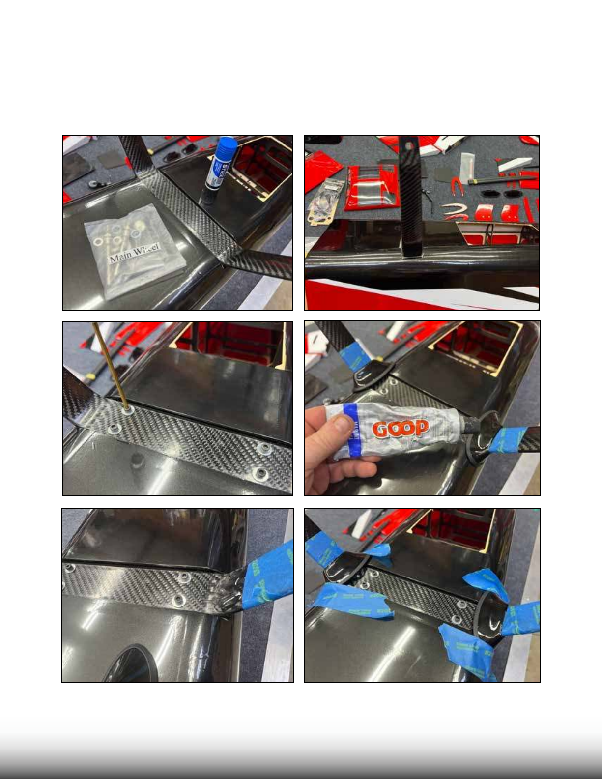
Locate the carbon ber landing gear and the Main Wheel hardware pack. e gear has a front,
and a back. To identify the front, note that the gear sweeps slight forward when installed. Use
4 screws and washers with loctite to install the landing gear as shown. Locate the gear “cu ”
fairings. Test t them to the landing gear. We recommend “Goop” adhesive to attach the cus.
Place masking tape to protect the gear surfeace as shown, apply a large dollop of Goop, slide on
the cu, and ax with masking tape until cured.
TURBO
B BUUSHSHMMAASSTTERER
Page 7
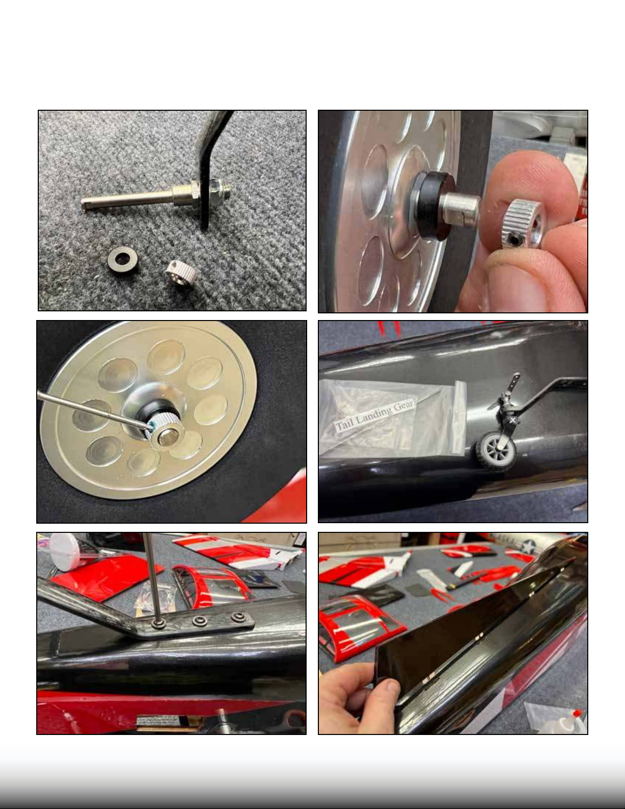
Attach the wheel axles to the landing gear by tightening the locking nuts. Slide on the wheels, and the
wheel spacers. Note the axles have at areas to accept the wheel collar set screws. Put loctite on the set
screw, then install and tighten the wheel collars. Locate the tailwheel and hardware bag. Using loctite,
mount the tailwheel to the fuselage using three screws as shown. Using a small amount of epoxy glue on
the wooden tabs, install the n on the bottom of the fusleage.
TURBO
B BUUSHSHMMAASSTTERER
Page 8
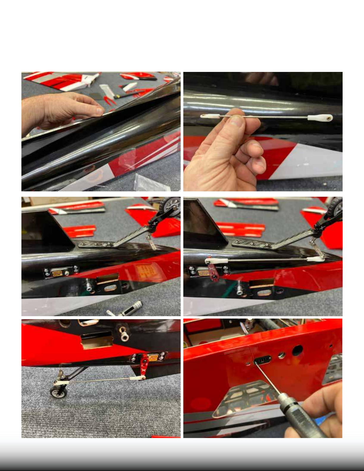
Assemble the tailwheel pushrod with the nylon ball link ends as shown. Remove the covering over the tailwheel steering servo mount location as shown. Install the servo wire extension onto the servo and mount
the servo. Install the pushrod between the servo arm and the tailwheel arm with 2mm screws, washers, and
locking nuts. Now is a good time to install the MPX wiring plugs into the pre-t locations in the fuselage,
using wood screws, as shown.
TURBO
B BUUSHSHMMAASSTTERER
Page 9
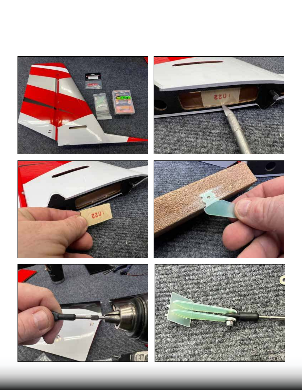
Locate the stab/rudder (it is pre-hinged for you), its hardware pack, and your servo, wire extesion, and
servo arm. Remove the wood tab on the bottom of the stab as shown. Locate the control horns. Sand
them lightly as shown in the area which will be glued. Assemble the plastic ball links onto the pushrods,
we use a cordless drill to assist. Note that the pushrods has one le hand, and one right hand thread.
Assemble the horns with the sqaure base plate, and the pushrod, with a screw, washers, and locking nuts
as shown.
TURBO
B BUUSHSHMMAASSTTERER
Page 10
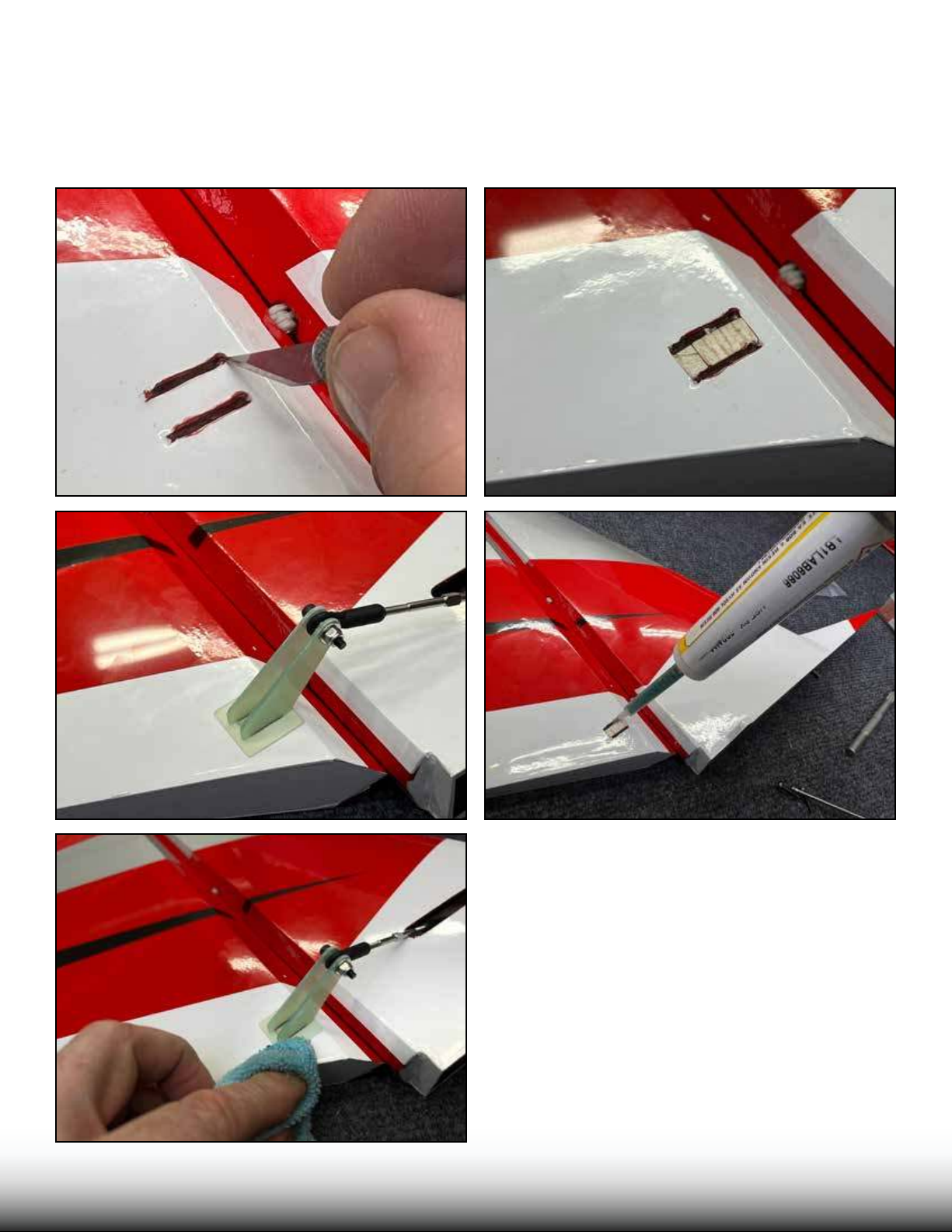
Remove the covering in the area between the slots on the rudder as shown. Test-t the horn assembly
into the slots. It should be tight, but should go in with moderate force. You may need to clean out the
slots with the hobby knife. Place epoxy glue into the slots and onto the horns. Push the horns into the
slot, seat it rmly. If any epoxy glue squeezes out, clean up with a paper towel soaked with denatured
alcohol.
TURBO
B BUUSHSHMMAASSTTERER
Page 11
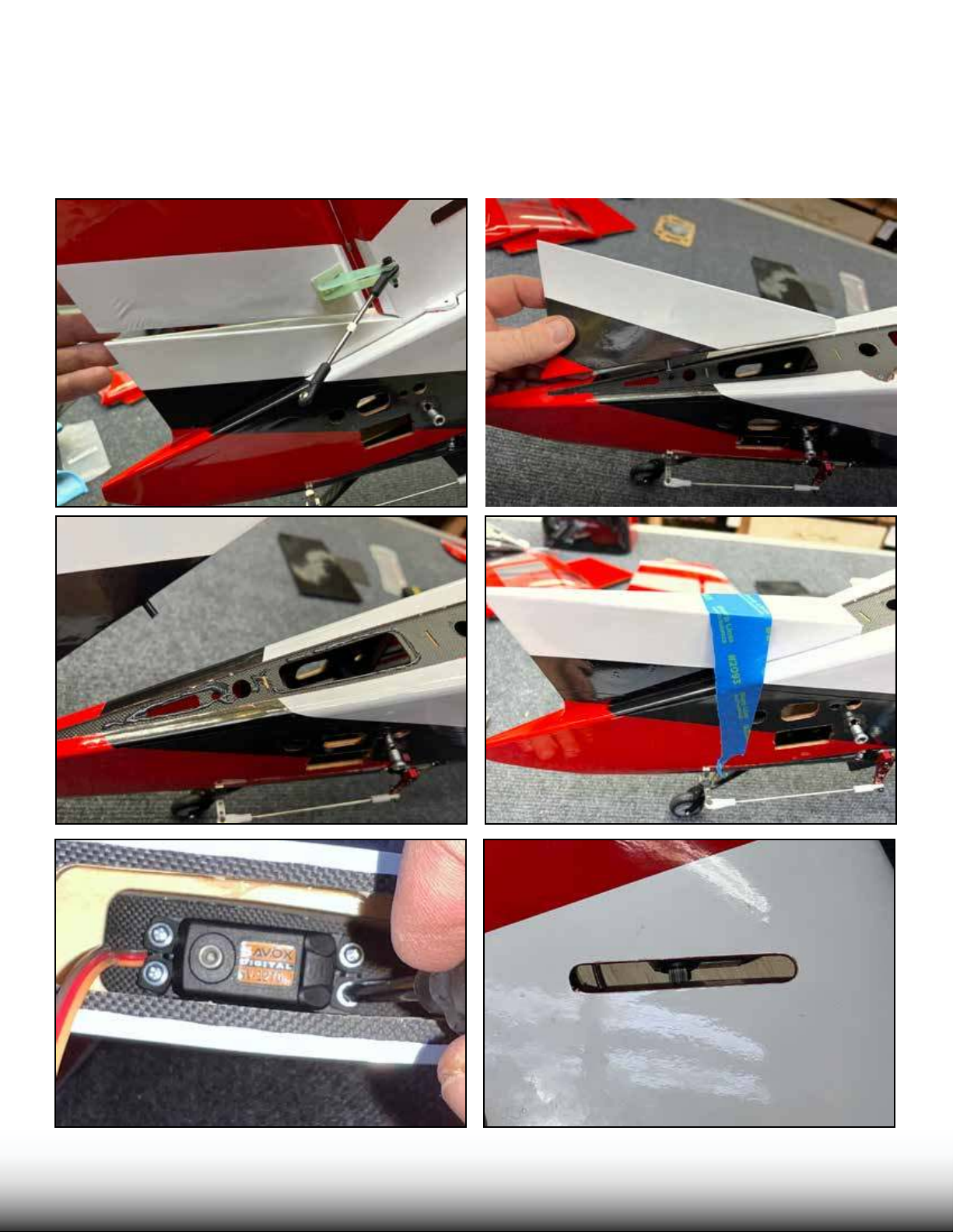
Locate the rudder extension piece which mounts to the fuselage. Check its t as shown. Glue to the fuselage with epoxy and use masking tape to hold the position while it cures. Now is a good time to center your servos using your radio system or a servo tester. Mount your rudder servo. e servo mounts
inside the vertical stab, go slowly and patiently as you place the servo into its mount. Note that the slot
in the stab is placed to t most common servos and arms, if your servo and arm combo happens to rub
the wood, you can trim the slot using a hobby knife and straight edge.
TURBO
B BUUSHSHMMAASSTTERER
Page 12
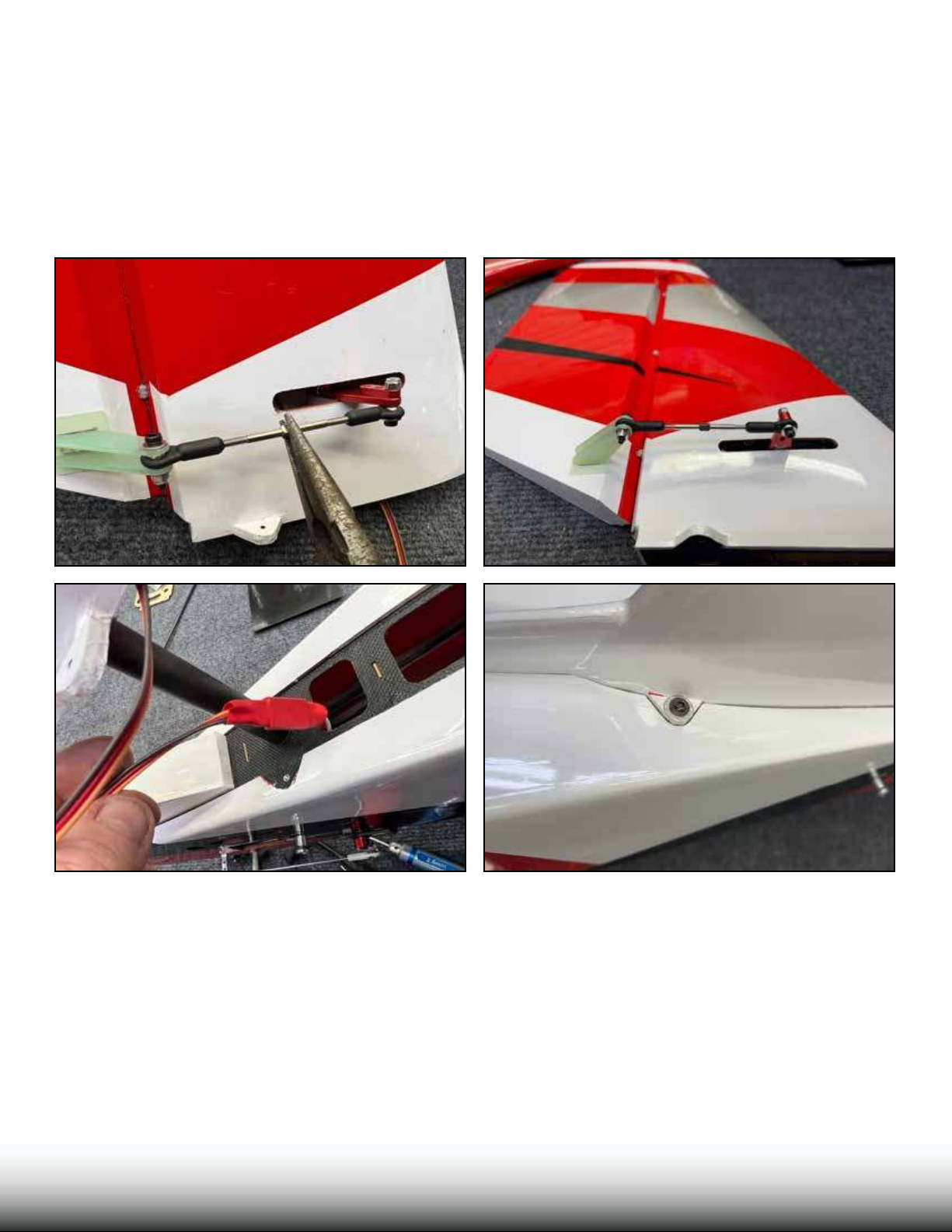
Install your servo arms, use loctite on the arm screws. Attach the pushrod to the arm with screw and
washers, use loctite or a locking nut for safety. Because the pushrod has one le, and one right hand
threads, you can adjust the length of the pushrod by rotating it. Adjust the length of the pushrod so that
the servo arm is 90 degrees as shown when the rudder is centered.
Run your servo wire extension through the plastic tube in the fuselage (now is a good time to also run
your elevator servo extensions). Because we do not expect to remove the vertical stab, we used heat shrink
tubing on the wire connection. Using the carbon mounting tube, install the stab onto the fuselage and
attach with screws and large washers with loctite.
TURBO
B BUUSHSHMMAASSTTERER
Page 13
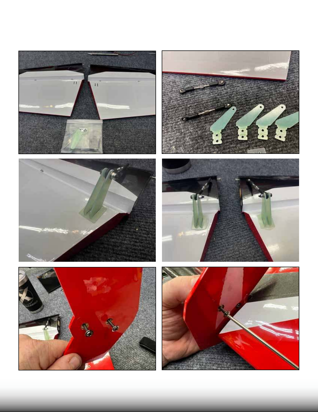
Locate the horizontal stabs/elevators. ese are pre-hinged for you. Install the control horns exactly
as you did on the rudder, and assemble the pushrods in the same way. Locate the ns for the stabs and
install with screws and loctite as shown.
TURBO
B BUUSHSHMMAASSTTERER
Page 14
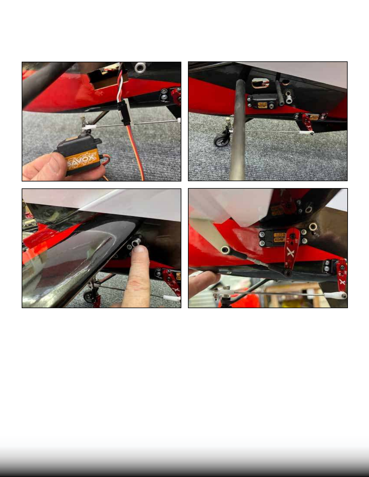
Locate the elevator servos, make sure they are centered. Plug them into the elevator wire extensions, because we expect to remove the stabs for transport, we use a servo plug lock on the connection. Using the
front and rear carbon stab tubes, install the stabs and engage the stab locks as shown. Install the servo arm
with loctite and attach the pushrod using loctite or locking nuts.
TURBO
B BUUSHSHMMAASSTTERER
Page 15
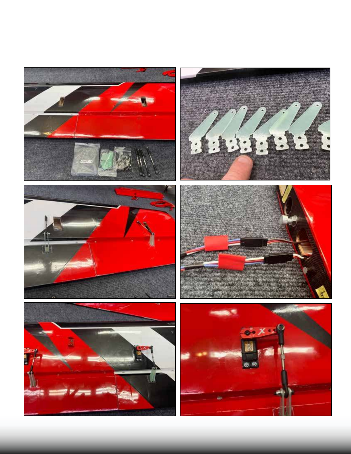
Locate the wings and Main Wing hardware pack. e wings are pre-hinged for you. Asemble the aileron and ap pushrods. All 8 control horns are identical. Sand and install them just as you did the
rudder and elevator horns. Attach your servo wire extension to the aileron aervo and feed through
the wing. Some servos will not need an extension in the ap location. Install your servos, and install
servo arms with loctite. Attach the pushrods and adjust to length as shown. We attached the MPX
servo plug and used heat shrink tubing on the connections.
TURBO
B BUUSHSHMMAASSTTERER
Page 16
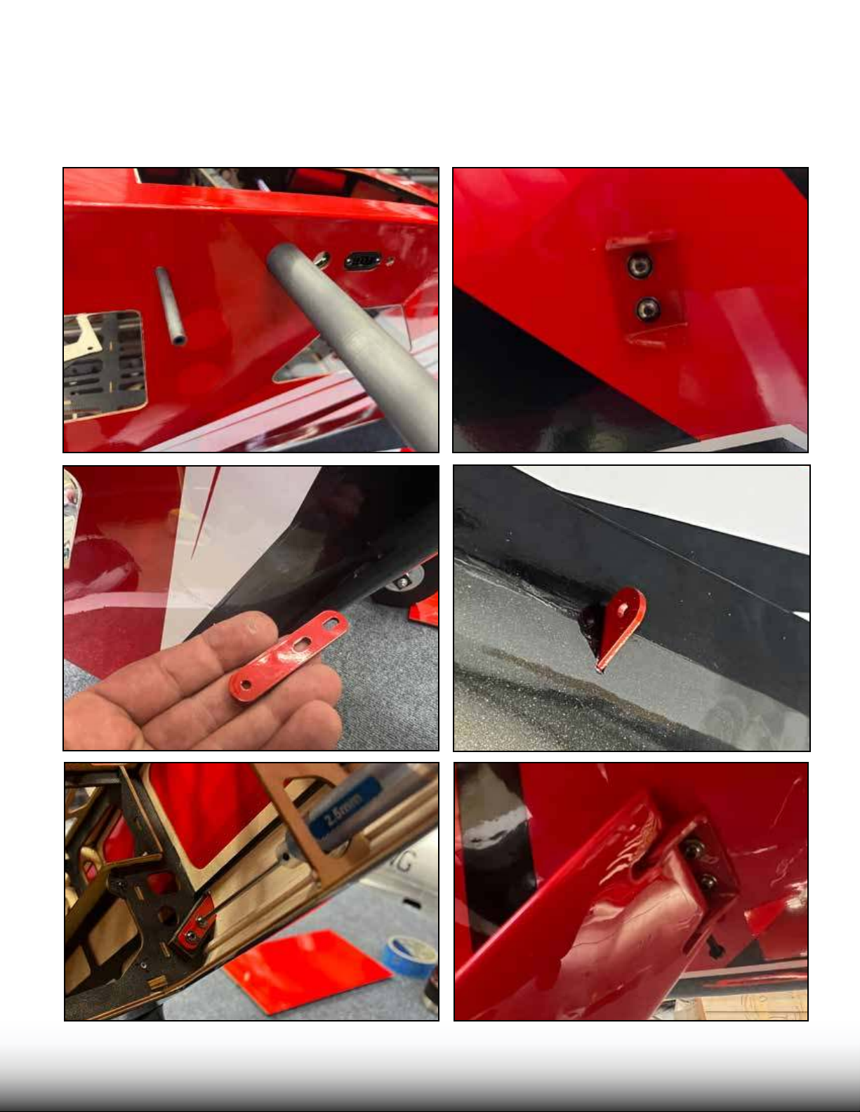
Locate the two carbon wing tubes and slide into the fuselage as shown. Locate the wing strut brackets.Cut
a slit in the covering to allow the fuselage-side bracket to protrude. Loosely install the wing side and fuselage side brackets for the wing struts with loctite, but do not fully tighten. Slide the wings on the tubes all
the way and close the wing latches inside the fuselage. Install the struts with long screws as shown. Once
the struts are installed, then we know the strut brackets are in the correct locations. Tighten the strut
bracket screws fully.
TURBO
B BUUSHSHMMAASSTTERER
Page 17
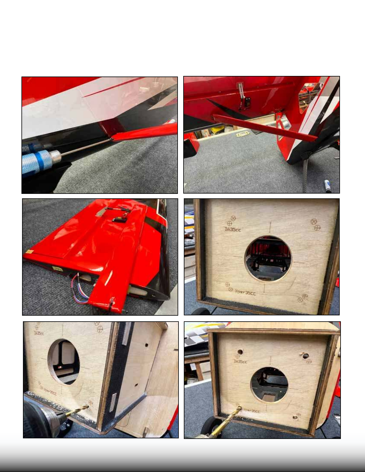
When the wings are removed from the airplane, the struts lay at against the wing and will t into the
wing bags for transport. e long axle screw on the wing-side strut mount should be locked in place
with a small drop of CA under the screw head.
e rewall of your aircra is marked with two common bolt pattern for engine/motor mounting.
One ts the GP-38/DA-35 gas engines, the other ts the XPWR 35cc and 40cc brushless motors.
Drill the appropriate holes, rst with a small bit diameter bit, then the correct nal size.
TURBO
B BUUSHSHMMAASSTTERER
Page 18
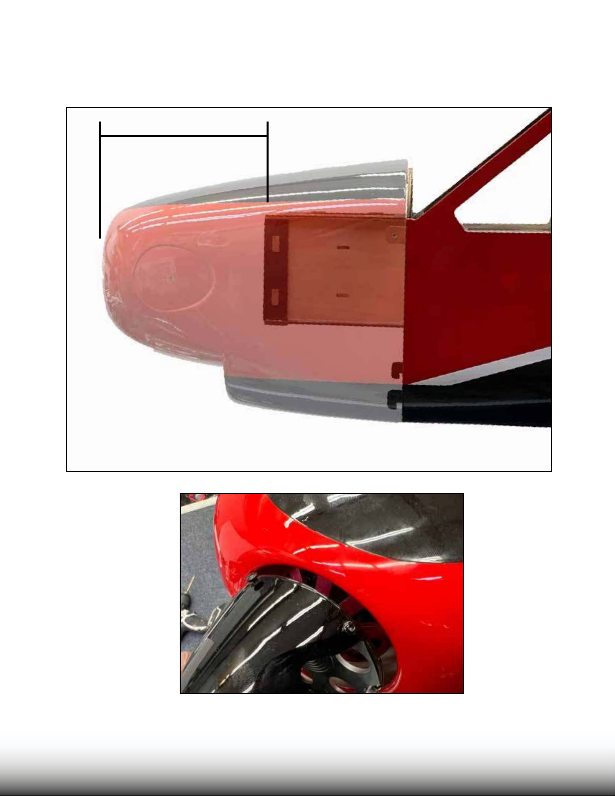
e distance between the rewall surface and the front of the cowl on your bushmaster is
approximately 163mm. is matches the length of common gas engines with their included standos/spacers. We do not want a tight spinner-to-cowl t on the Bushmaster, leave
3-4mm for cooling air to enter the cowling.
163mm/ 6.4 in
TURBO
B BUUSHSHMMAASSTTERER
Page 19
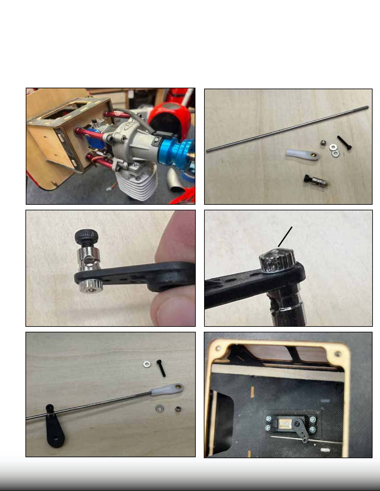
If using a gas engine, install onto the rewall, trimming the rewall as necessary to t the carburetor. Use
large diameter washers on the rewall to spread the load of the engine mounting screws, on front and
back if possible. Use loctite to install the screws. Locate the “ottle” hardware pack. Inside is a pushrod
with one threaded end. e threaded end accepts the nylon ball link. is attaches to the carburetor throttle arm. e other end of the pushrod is smooth. e servo arm connector, when mounted on the servo
arm, must spin freely. Tighten the servo connector nut as shown until the connector is snug and doesnt
wobble, but can still rotate freely. Place a drop of medium CA as shown on the nut and apply CA accelerator. Install the throttle servo as shown, install and adjust the linkage, using loctite on the set screw.
MED CA Glue
TURBO
B BUUSHSHMMAASSTTERER
Page 20
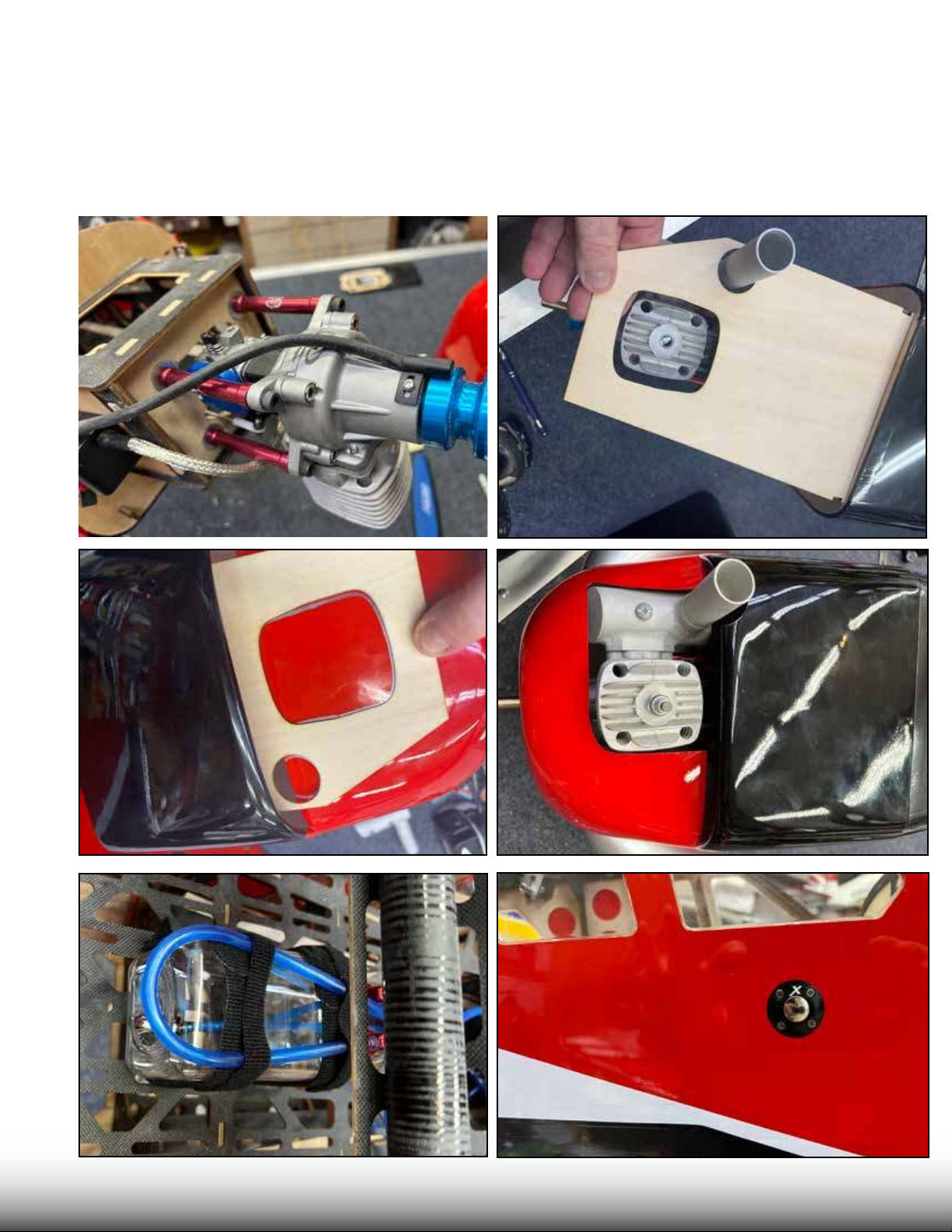
Mount the ignition unit to the side of the motor box using adhesive velcro, velcro straps, and cushioning
foam if desired. To cut the bottom of the cowl for clearance and cooling, it is helpful to make a template
from heavy paper or card stock or thin plywood. Use this template to mark the cowl before cutting.
Wear eye and lung protection when cutting the berglass cowl. Go slowly, and test-t frequently while
working. For this installation we trimmed the muer exit tube approximately 20mm (3/4 in). Mount
your fuel tank directly under the wing spar on the tray. Use strong velcro straps. Hook up your fuel lines
for carb, vent, and ll. Remember to place a loop in the vent line as shown so that fuel does not siphon
out of the tank during maneuvers. Install your fuel dot.
TURBO
B BUUSHSHMMAASSTTERER
Page 21
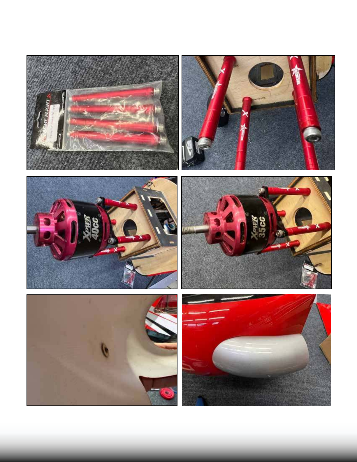
If you are using either of the recommended brushless motors, the recommended Blazing Star standos can be easily adjusted for proper length by adding or subtracting sections. Install with loctite.
Install the turbo exhaust pipes with a screw and loctite.
TURBO
B BUUSHSHMMAASSTTERER
Page 22
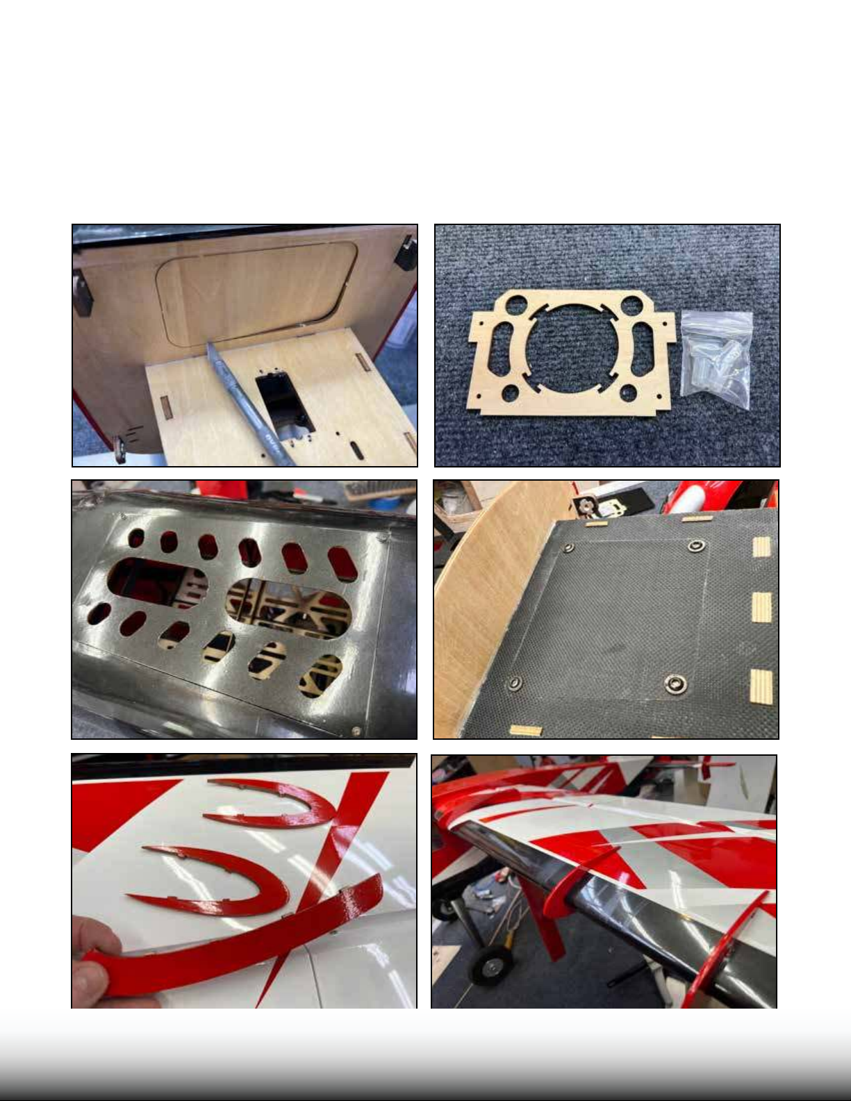
If you are using a tuned pipe or canister exhaust on a gas engine, remove the panel on the bottom of
the F1 former. We also recommend removing this panel if you are running an electric power system.
Only if you are running a gas engine with stock muer should you leave this panel in place. If you
are using a tuned pipe or canister, we have included an exhaust mount with vibration-isolators which
screws into the fuselage. For electric, remove the covering over the vents on the bottom access plate as
shown and install with wood screws. ere are additional cooling vents on the bottom of the fuselage
which you can open if you need more cooling. Install the top plate onto the motor box with loctite.
Locate the wing fence pieces, install onto the wing with epoxy glue. Clean up any excess epoxy with
denatured alcohol.
TURBO
B BUUSHSHMMAASSTTERER
Page 23
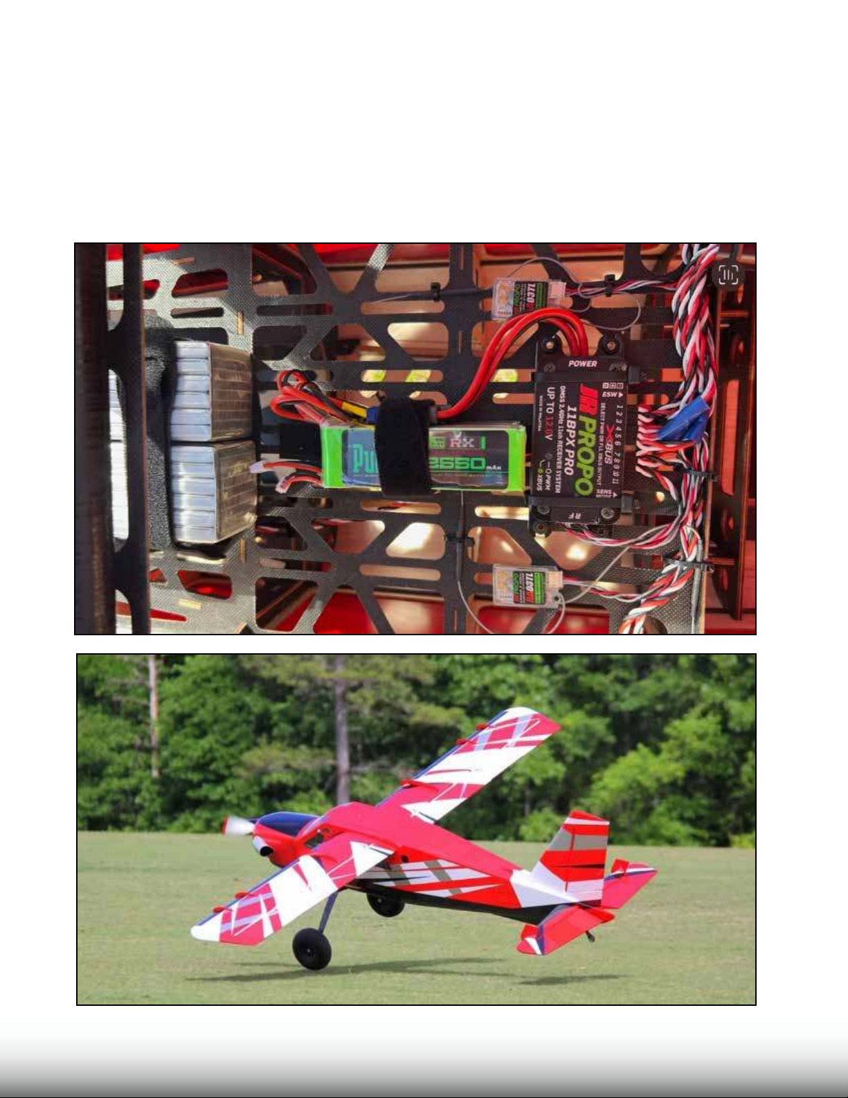
Balance your aircra. We recommend balancing it so that it simply hangs level when lied by the
main wing tube. is is our favorite balance point for all types of ying. Set your control throws
accoring to the setup sheet in the front of this manual. Test your power system in a safe manner
on the ground, and range-check your radio system. Verify that your control surfaces move in the
correct directions before ight.
e most common radio mix for the Bushmaster is to mix aps to ailerons to give the fuction of
large, full-span ailerons. is increases the roll rate. ere are many other mixes you can experiment with on the Bushmaster. Check over the aircra for any loose fasteners aer the rst ight
and every several ights thereaer. We hope you enjoy your Bushmaster!
TURBO
B BUUSHSHMMAASSTTERER
 Loading...