

Page 1
Page 2

Please take a few moments to read this instruction manual before beginning assembly. We have outlined a
fast, clear and easy method to assemble this aircraft and familiarizing yourself with this process will aid in a
quick, easy build.
Please read the following paragraph before beginning assembly of your aircraft!
THIS IS NOT A TOY! Serious injury, destruction of property, or even death may result from the misuse of this product. Extreme
Flight RC is providing you, the consumer with a very high quality model aircraft component kit, from which you, the consumer,
will assemble a flying model. It is beyond our control to monitor the finished aircraft you produce. Extreme Flight RC will in no
way accept or assume responsibility or liability for damages resulting from the use of this user assembled product. This aircraft
should be flown in accordance to the AMA safety code. It is highly recommended that you join the Academy of Model Aeronautics in order to be properly insured, and to operate your model at AMA sanctioned flying fields only. If you are not willing to
accept ALL liability for the use of this product, please return it to the place of purchase immediately.
Extreme Flight RC, Ltd. guarantees this kit to be free of defects in materials and workmanship for a period of 30 DAYS from the
date of purchase. All warranty claims must be accompanied by the original dated receipt. This warranty is extended to the original purchaser of the aircraft kit only.
Extreme Flight RC in no way warranties its aircraft against flutter. We have put these aircraft through the most grueling flight
tests imaginable and have not experienced any control surface flutter. Proper servo selection and linkage set-up is absolutely essential. Inadequate servos or improper linkage set up may result in flutter and possibly the complete destruction of your aircraft.
If you are not experienced in this type of linkage set-up or have questions regarding servo choices, please contact us at info@
extremeflightrc.com or 770-887-1794. It is your responsibility to ensure the airworthiness of your model.
A few tips to ensure success:
1. We are very pleased with the level of craftsmanship displayed by the builders in our factory. Through hundreds of grueling
test flights containing maneuvers that no aircraft should be subjected to, our prototypes have remained rigid and completely
airworthy. Having said that, it is impossible for us to inspect every glue joint in the aircraft. Take a few minutes and apply some
medium CA to high stress areas such as the aileron servo mounting trays , landing gear mount, anti rotation pins, wing and stab
root ribs, etc.
2. Having survived the journey half way around the world while experiencing several climate changes, it is not uncommon for a
few wrinkles to develop in the covering. Fear not! These are not manufacturing defects, and are easily removed with a little bit of
heat. Use a sealing iron to go over all seams, stripes and sharp points in the covering scheme. You may want to apply a drop of
clear fingernail polish at the tip of all sharp points to prevent them from lifting. To remove wrinkles use a 100% cotton tee-shirt
or microfiber cloth and your heat gun and heat the covering while gently rubbing the covering onto the wood with the t-shirt or
cloth. Be careful not to use too much heat as the covering may shrink too much and begin to lift at the edges. Take your time,
and a beautiful, paint like finish is attainable. If you need to repair any covering during the life of your aircraft, the colors are:
Yellow scheme: Bright Yellow, Black and Deep Blue in the Ultracote system.
Red/white/blue scheme: True Red, White, Midnight Blue in the Ultracote system.
3. By the time your aircraft arrives at your door step it will have been handled by a lot of people. Occasionally there are small
dings or imperfections on some of the surfaces. An eective method to restore these imperfections to original condition is to use
a very fine tipped hypodermic needle to inject a drop of water under the covering material and into the ding in the wood. Apply
heat to the area with a sealing iron and the imperfection will disappear. Deeper marks may require that this process be repeated
a couple of times to achieve the desired result, but you will be surprised at how well this technique works.
Congratulations on your purchase of the Extreme Flight RC 74” Slick 580 EXP ARF! Designed specifically
to handle the high G loads of Xtreme Aerobatics (XA), Freestyle routines, aggressive 3D maneuvers and
precision aerobatics, the Slick was born of the desire to meet the demands of today’s top ultra-aggressive
pilots.
Featuring carbon fiber square tube wing spars, D-tube wing design, carbon fuselage longerons, composite-reinforced fuselage formers, tank/battery tray, firewall, motor box and fuselage sides, as well as aluminum landing gear mount, quick-mount cowl, dual hatch latches, pre-jigging stabilizer, multi-airfoil wing
design, carbon fiber wing tube, carbon landing gear, complete competition-grade hardware package, and
many other features, the Slick 580 is the ultimate 35CC aerobatic aircraft on the market.
Please refer to the ARF Assembly Resources page on our website
under the Multimedia drop down menu for informative videos to
aid in the assembly and set-up of your aircraft.
4. DO NOT SKIMP ON SERVOS! Your aircraft is equipped with very large control surfaces that deflect over 45 degrees. A lot of
servo power is required to prevent flutter and to maintain the required deflection for maneuvers. We absolutely recommend the
use of METAL GEARED servos with a minimum of 300 oz. inches of torque.
5. Use a high quality epoxy for installing the composite control horns and hinges. We highly recommend the use of Pacer
Z-Poxy 30 minute formula. We have used this glue for many years with zero failures.
6. You may want to add a bead of RC-56 Canopy glue to the intersection of the canopy/hatch and its wood frame for additional
strength and resistance to vibration. DO NOT USE CA here as it will fog the canopy.
7. Your aircraft is built using very modern construction techniques and is very light weight for its size. As with any high performance machine, regular inspection and maintenance is a must. While disassembling your aircraft after a flying session, pay
close attention and inspect glue joints, linkages and loose covering to be sure the airframe is sound. A few minutes spent doing
this will help maintain airframe longevity.
8. Be sure to put a drop of blue Loctite thread locker on every bolt on this aircraft! Failure to do so may cost you your aircraft!
This includes servo screws!
9.We highly recommend a Desert Aircraft DA-35 gasoline engine if you prefer gas power in your slick. If you prefer electric, we
recommend the Extreme Flight XPWR 30CC motor with Castle Creation Edge HV speed controller, and 2 x 6S 3000-3700mah
lipo batteries, arranged in series for 12S.
Page 3
1
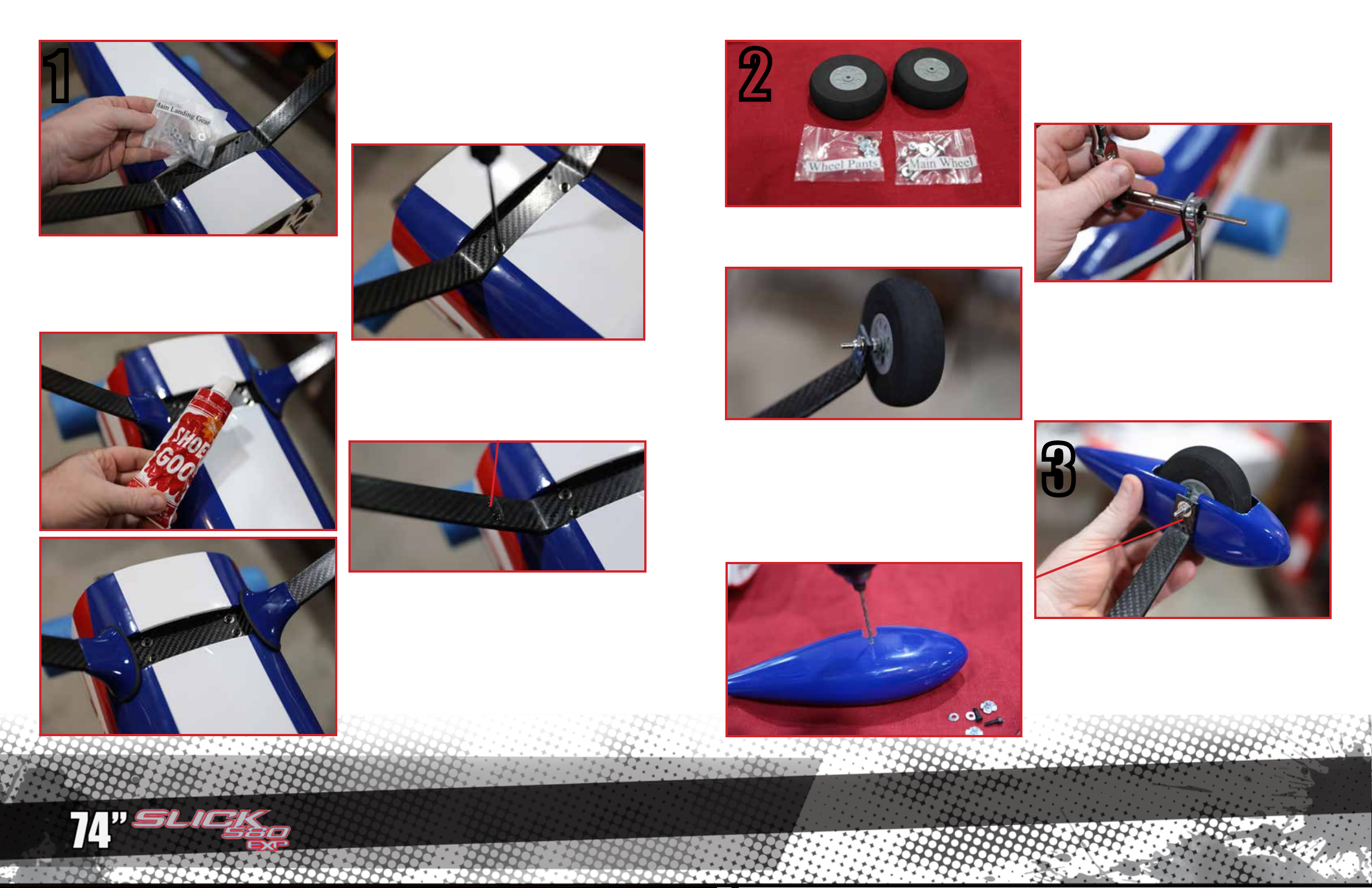
Attach the landing gear to the fuselage using the
4mm screws, washers and nyloc nuts. You will need
to use pliers to hold the nyloc nuts inside the fuselage as you tighten the screws.
Locate the carbon fiber landing gear. Note that it
has a front and a rear, it is designed to sweep forward toward the nose of the airplane. Locate the
Main Landing gear hardware pack.
The landing gear-to-fuselage fairings are attached
to the landing gear and fuselage with Shoe-Goo
type silicone adhesive. First, slide the fairings onto
the gear, and check for fit to determine the front and
re ar.
2
Attach the axles to the carbon landing gear wth
washers and nyloc nuts as shown.
Trial-fit the wheel pants onto the landing gear as
shown. To get the pants to fit on properly, you will
need to align the wheel axle so that the opening
in the pant slides smoothly over it, and the wheel
collars so that the wheel is centered in the pant.
Holding the pant level, mark the pant through the
hole indicated
Locate the main wheels, the main wheels hardware
pack, and the wheel pants hardware pack.
Slide wheel collars onto the axles, then the main
wheels, then outer wheel collars. The wheel collars
locate the wheels on the axles, when you install the
pants you will need to fine-tune the location of the
wheels. Apply a drop of loctite to the set screws in
the wheel collars and tighten them.
3
Place a large dollop of goo-adhesive onto the gear
leg as shown, then slide the fairings into the gear
legs. The Goo will fill up the end of the fairings.
Place an additional dollop of Goo where the fairings
contact the fuselage. Allow the Goo to dry while you
install the wheels and wheel pants.
Drill the wheel pant on the mark you made as
shown. Start with a 1/8” (3mm) bit.
Page 4
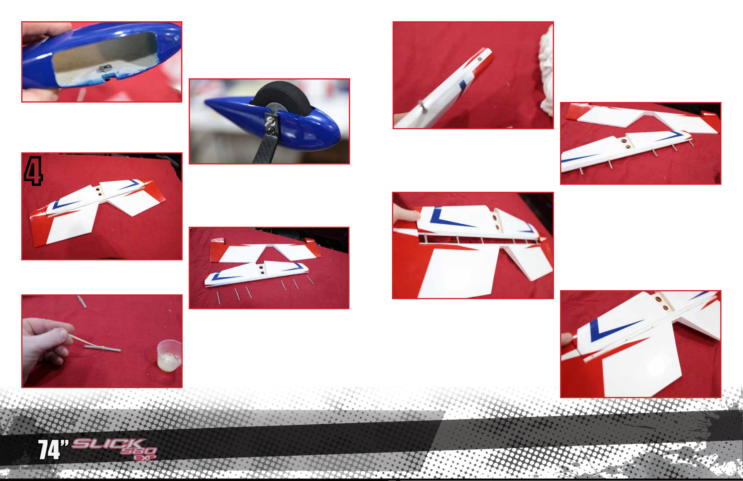
Install the wheel pants onto the landing gear. Apply
loctite to the 3mm screws and fully install them into
the blind nuts and tighten as shown.
4
Increase the drill size until you can press the blind
nut into the hole as shown. Use the 3mm screw and
washer to draw the blind nut into the hole part way
and the spikes on the blind nut engage the fiberglass.
Locate the horizontal stabilizer and elevators. In this
step we will hinge the elevators, and we will hinge all
the other surfaces in the same manner. Note that for
hinging, we will be using 30 minute spoxy for adhesive, and denatured alcohol and a rag for cleanup.
Once all six hinges have been lubricated, mix up a
batch of 30 minute epoxy and place several large
drops of glue into each of the hinge holes in the
stabilizer. Press the hinges into the holes, and turn
them so that they flex in the correct direction.
When you press the hinges into the hinge holes,
some epoxy may squeeze out. Use alcohol on a rag
to clean up any excess epoxy.
Put several large drops of epoxy in the hinge holes
in the elevator and fit the elevator and stabilizer together. Clean up any excess epoxy which squeezes
out.
Pull the elevators and stab apart and remove the six
hinges.
First, we must protect the hinges from any glue
entering the moving portion. Place a drop of lubricating oil into the center portion of the hinge where
the axle pin is. It only takes a tiny amount of oil. If
you accidentally get oil on the gluing portion of the
hinges, clean it o with alcohol.
Once you have the parts fit together, make sure the
elevator can flex up and down at least 45 degrees.
There should be a small gap, about 1/32” (1mm)
between the stabilizer and elevators. Allow the epoxy to cure.
Page 5
5
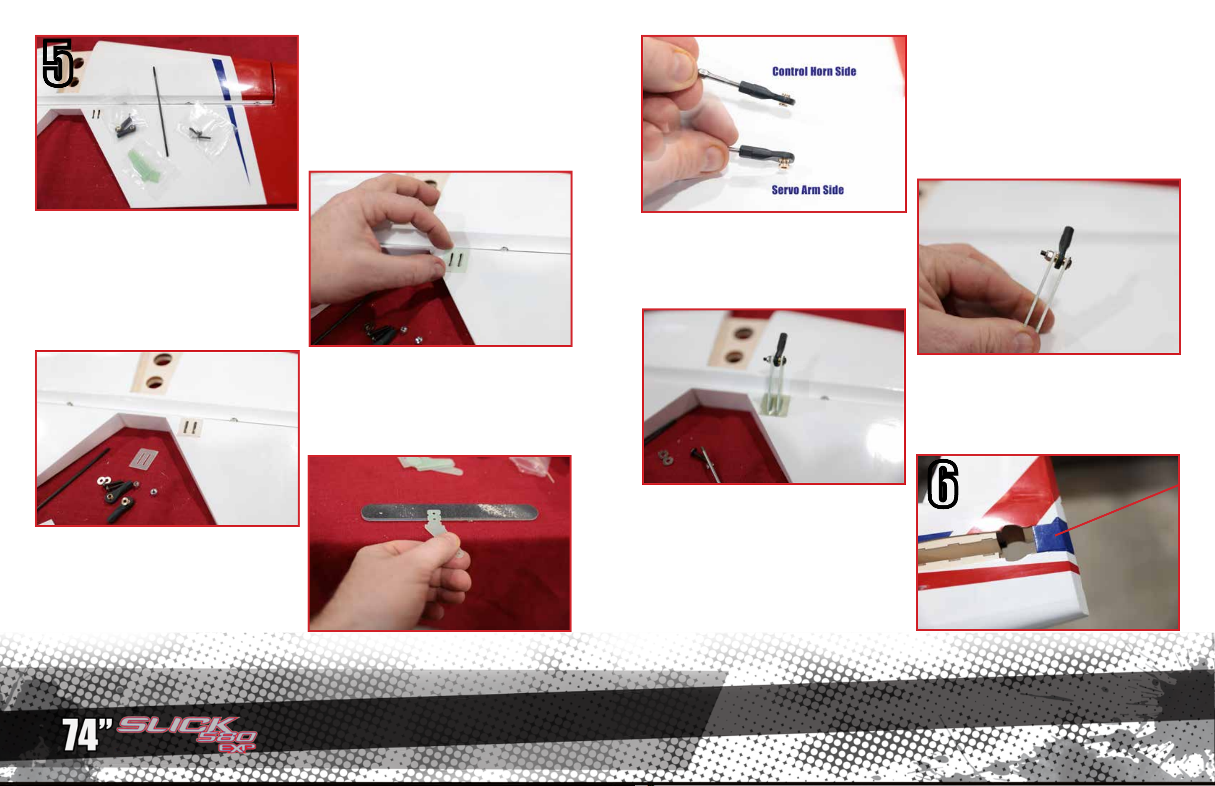
Once the hinges are cured, locate the hardware
for the elevator as shown. We will be installing the
control horn, and we will install all remaining horns
using this procedure.
Note that the 74” Slick 580 EXP uses two dierent
types of ball joints. One is symmetrical and is used
on the fiberglass control horns i the surfaces. The
other is asymmetrical, with a raised pedestal on one
side, and it is used on the servo arms.
Locate the slots cut into the elevator. Place the fiberglass baseplate of the horn over the slots and use
it as a template to cut the covering to expose bare
wood.
Use sandpaper or an emery file to roughen the part
of the control horn which will be inserted into the
elevator. We do this to ensure the best possible glue
joint on this super-critical connection.
If necessary, clean out the slots in the elevator of
any stray wood fibers so the control horn can easily
be inserted.
Assemble the elevator control horn as shown, using
a 3mm screw with integral washer, ball link, washer
and nyloc nut.
This balsa block is held into postition in the fuselage with tape during shipping. Remove it and set it
aside.
Place the baseplate on the horn as shown, mix a
new batch of 30 minute epoxy, and coat the baseplate and legs of the horn assembly with epoxy.
Place more epoxy into the slots in the elevator and
insert the horn assembly. Clean up any excess epoxy which comes out. Allow to cure.
6
Page 6
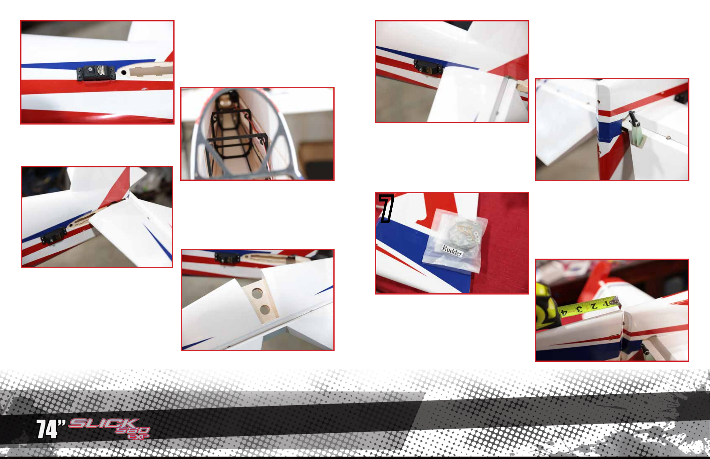
The Slick features hooks to secure your servo lead
in the fuselage.
Attach a servo wire extension onto your elevator
servo and secure it with a connector lock or tape.
We recommend a 24” (60 cm) extension for the
elevator servo. Install the servo into the fuselage. We
recommend Extreme Flight RC socket head servo
screws.
Test fit your horizontal stabilizer assembly into the
fuselage. Check for fit. Note how much force it takes
to slide the stab all the way forward into the slot until it contacts the front of the cutout. Make sure your
stab is correct side up.
Locate the balsa block you previously removed
from the tail. Slide it into position. Make certain the
elevator swings freely without interference from
the block. The block is soft balsa, it can easily be
trimmed or sanded to correct any interference.
Once you are satisfied with its fit, glue it in place
with epoxy or CA glue.
7
Slide the atabilizer into the slot. Make sure your stab
is correct side up. Push it all the way to the forward
end of the slot as shown. Clean any excess epoxy
with alcohol and a rag. Allow the epoxy to cure.
Locate the rudder and rudder hardware pack. the
rudder hinges will be installed into the fuselage and
rudder using the exact same technique you employed to install the elevator hinges in step 4. Once
the rudder is installed, allow the epoxy to cure.
Apply 30 minute epoxy glue to the bare wood area
of the stabilizer, top and bottom, and into the slot in
the fuselage.
Measure 2 inches (50mm) back form the rudder
hinge line as shown, and drill a 1/8” (3mm) hole in
the bottom of the rudder.
Page 7
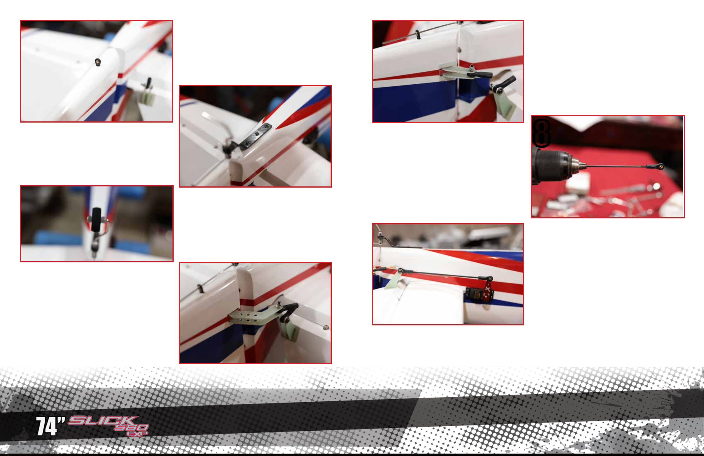
Locate one of the small ball-link ends, and using CA
glue, install it into the hole you drilled in the rudder,
as shown. This will be the guide for the tiller-wire
which steers the tail wheel.
Apply epoxy glue to the rudder horn where it will be
inside the slot in the rudder. Press the horn into the
rudder until it is centered. Assemble the ball link and
screw on the opposite side, make certain the horn
assmbly is centered, and add the square horn plates
with epoxy as shown. Clean up any excess epoxy
with alcohol and allow to cure.
Using three wood screws, install the tail wheel as
shown. The tail wheel axle of swing should be in line
with the rudder hinges. As you install each screw,
screw it in half-way, then remove it and add a drop
of CA glue to the hole, then screw the screw all the
way in.
The rudder horn is double-sided. Use sandpaper or
an emery board to scu the middle part which will
lgue into the rudder. Assemble one side with ball link
as you did the elevator horn. Place part-way into the
rudder and shown
Install the two tail-wheel collars and the tail wheel
as shown. Use Loctite on the set screws of the collars.
Locate the elevator pushrod, and remove the balllink
from the elevator horn. To assemble the elevator
pushrod, you will need to screw the ball links onto
the elevator pushrod. We prefer to use a cordless
drill. Chuck the bare pushrod in and hold the first
ball link, and screw in as shown. Then, we turn the
shaft around, and chuck the ball link into the drill
to install the second ball link. NOTE: both ends of
the elevator pushod are conventional “right hand”
threads.
8
Install the servo arm and pushrod. We recommend
Extreme Flight RC aluminum servo arms. Pictured is
a 1.5” arm, but we recommend a 2.0” arm for maximum options in control throw. Install the pushrod
with 3mm hanrdware, note that you must use either
a nyloc nut or loctite on the screw which attaches
the ball link to the servo arm.
Page 8
9
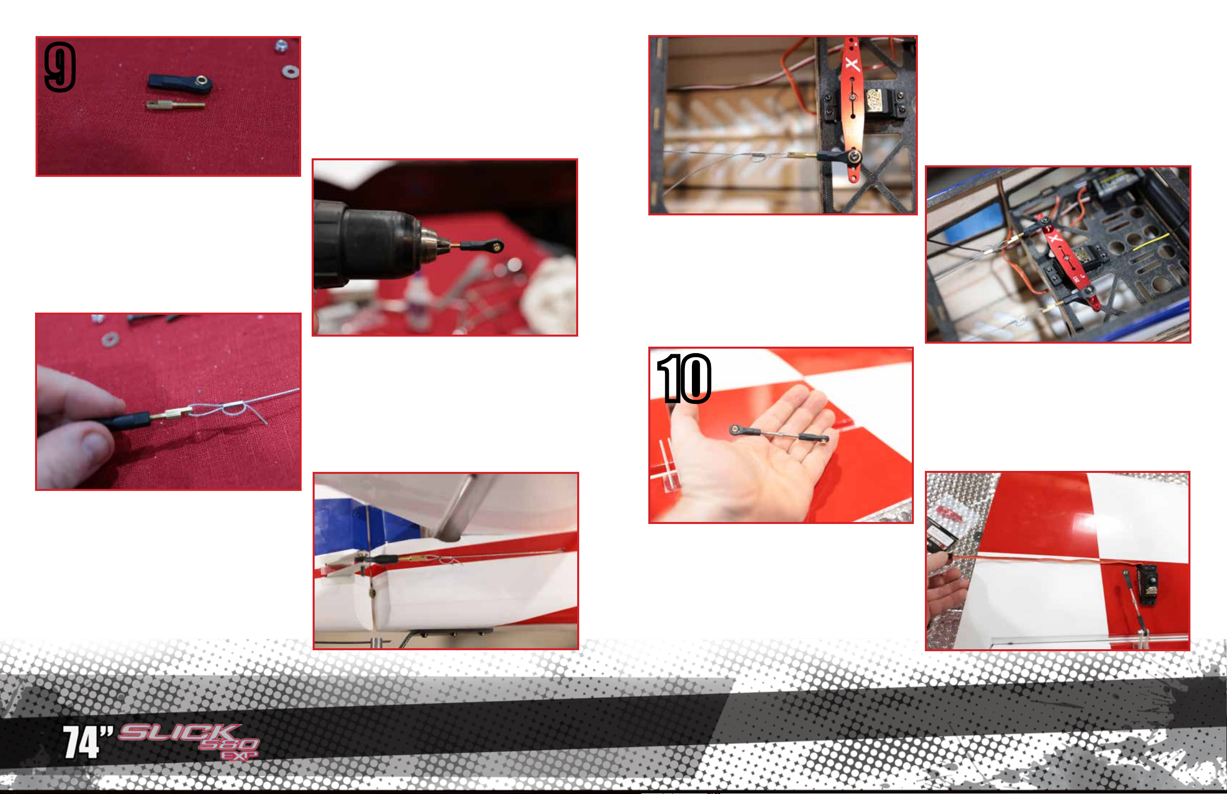
We prefer to use a cordless drill as shown for this
job. Screw the cable ends 5-6 threads into the bal
links. Note that these are all conventional “right
hand” threads.
The rudder connnection is by pull-pull cable. The
ends of the cables are made by screwing the brass
cable ends into the nylon ball links.
Cross the cable across each other inside the fuselage to form an X shape. Install your rudder servo
and arm as shown. Pictured is the Extreme Flight
RC 4” aluminum arm, our recommendation. Install
the front cable ends and attach to servo arm, as
shown. Screw the cable ends farther into the ball
links to tighten the cables. Cut o excess cable,
leaving 1/2” (12mm) end from the crimps.
Note that while we need our rudder cables to be
snug, and not slack or droppy, we also do not want
them overly tight. We adjust our cables with the
servo and the rudder at center to be just snug. To o
tight cables put additional strain on the rudder
servo. Also, it is normal for the cables to have some
slack on one side at full deflection.
Locate the openings in the rear of the aircraft for
the cables, and thread the cable inside. Install the
contorl horn end of the cable onto the horn with
3mm screw, washer, and nyloc nut. thread the other
end of the cable inside the fuselage to the front.
Assemble one end of each cable outside the aircraft
as shown. Slide the tubular “crimp” onto the cable,
loop as shown through the cable end, and flatten the
“crimp” tube with pliers. Pull on the cable to check
the strength of the crimp.
10
We used the MKS HV1220 servs on this build, and
they have a long enough servo lead to reach the
wing root without an extension. Your servos may
need an extension wire. Install your servos in the
orientation shown.
The aileron hinges and horns are installed in exactly the same manner as the elevator and rudder
hinges and horns. Once this is completed, assemble
the aileron pushrods as shown. Note that these are
threaded one right hand, one left hand. This allows
them to be adjusted without removal from the aircraft.
Page 9
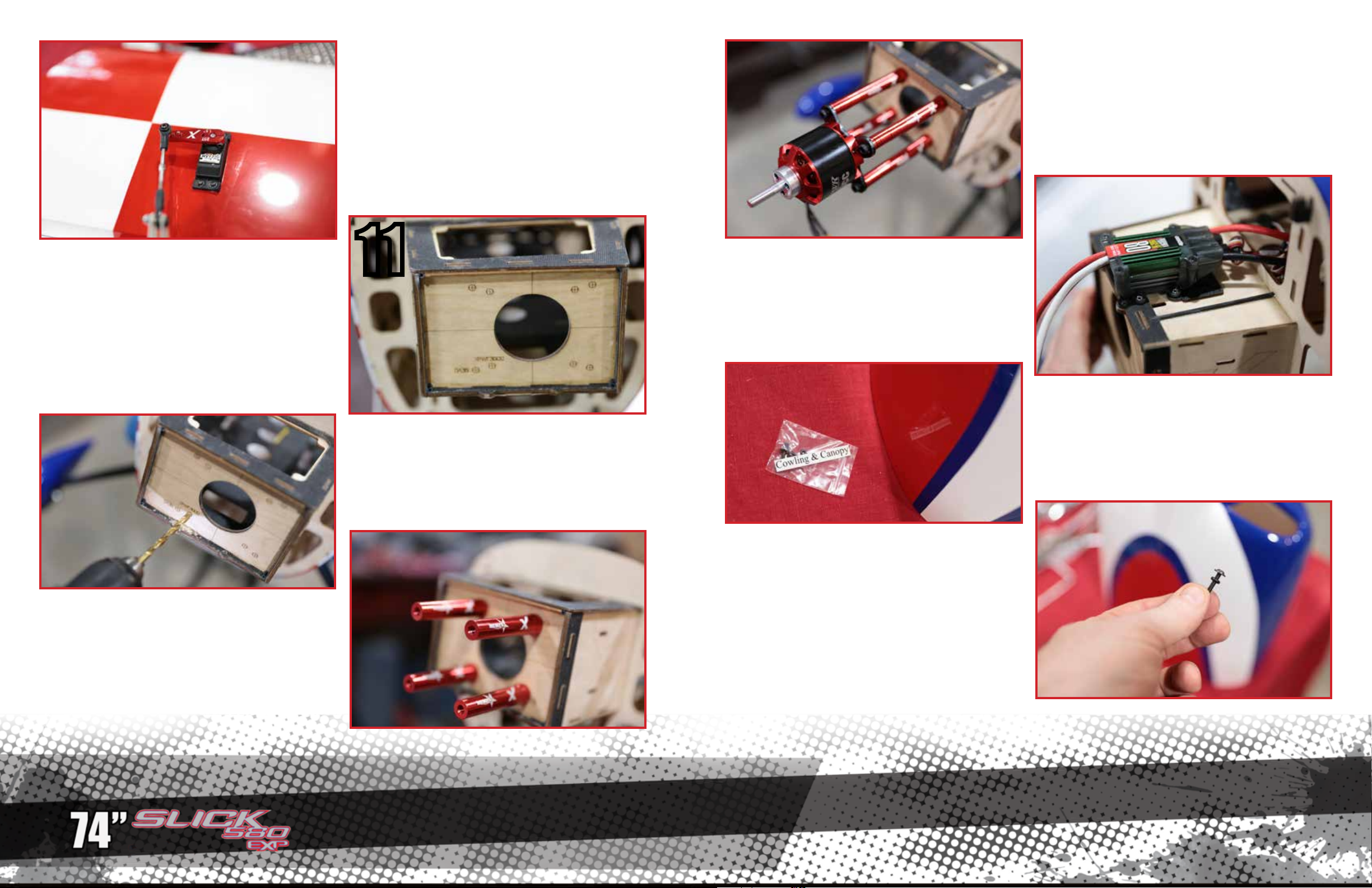
We recommend Extreme Flight RC 1.5” aluminum
servo arms for the ailerons. Adjust the pushrod
length by rotating them with using the nut in the
center of the pushrod.
The XPWR 30CC motor provides over 3000 watts
of power and is perfect for this model.
The firewall of the Slick 580 EXP is pre-marked
for either the XPWR 30CC brushless motor or the
DA-35 gasoline engine. These are our recommendations for power systems, but a variety of 30-35CC
gasoline engines and 2500-3000 Watt electric
power system will work well. The firewall is also
marked with center lines to allow you to align other
mounts and templates.
11
Drill the firewall for the power system of your
choice. Start with a 1/8” (3mm) drill bit and expland the holes with a larger bit of the correct size for
your mount screws.
The bottom of the motor box on your Slick is design
witha custom mounting area for Castle Creations
Edge 80HV and 120HV speed controllers. The
speed controllers mount using 4 servo screws.
Locate the cowling and the hardware pack. The
cowling on your Slick is very convenient, using only
two screws to retain it.
The cowling screw come with o-rings, install these
onto the screws as shown. These prevent the
screws from vibrating loose.
For XPWR 30CC electric power, install the bases
of the Extreme Flight STANDARD-LONG Blazing
Star standos with loctite. Install the extensions to
achieve 95mm length, then install the motor using
loctite. For any installation, the distance between
the firewall and spinner backplate is 163mm.
Page 10
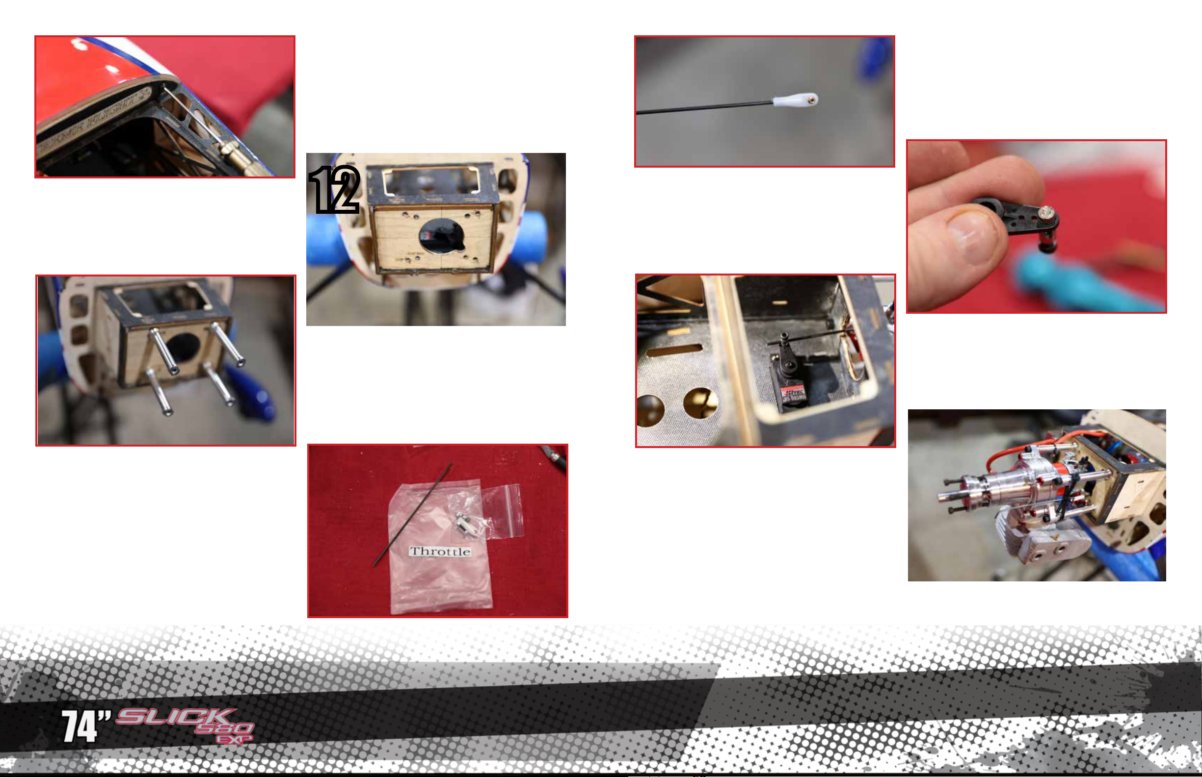
Install the cowling by sliding it up onto the lower
hooks, from the bottom, and installing the two cowl
screws as shown.
Assemble the throttle pushrod as shown.
Alternately, to install a DA-35 engine, drill the firewall on that mounting pattern and make this small
notch in the firewall as shown to provide clearance
for the throttle pushrod.
Locate the hardware for throttle pushrod.
12
Install the standos which came with your DA engine using loctite.
Assemble the throtle pushrod connector onto the
throttle servo arm so that it can spin freely. Add a
drop of CA to the nut to lock it in place so it doesn’t
vibrate o.
Install the throttle servo as shown. The throttle
pushrod installs as shown.
Install the engine and muer. using loctite on all
screws.
Page 11
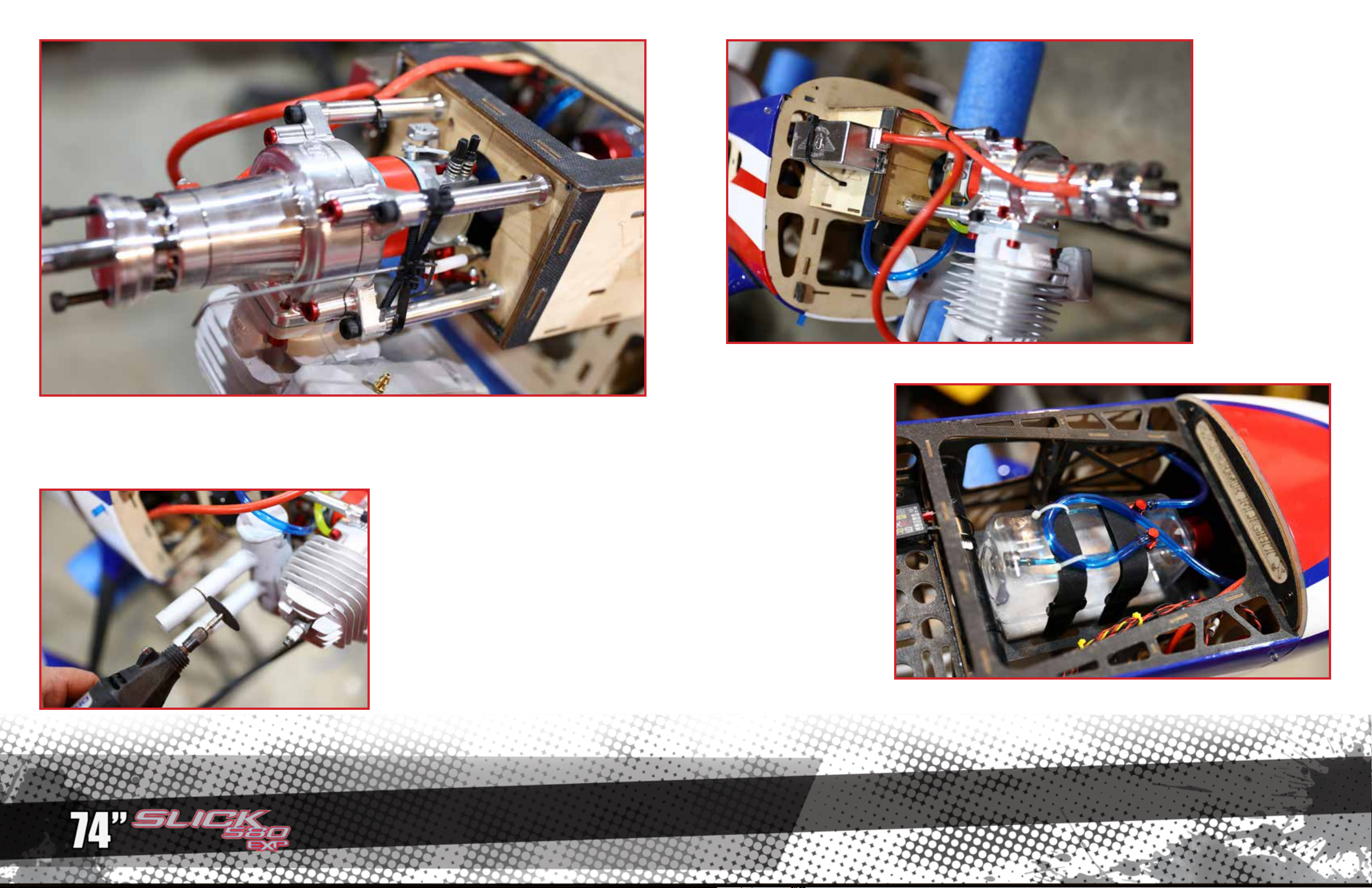
On either side of
the motor box is a
mounting location
for your ignition box.
Place vibration-absorbing foam in-between the box and
the aircraft.
Ther are a variety of choke linkages possible on the DA-35. Here, we illustrate a forward choke, accessed
through the cooling hole on the front of the cowling. We use zip ties as shown to make a bracket for the
rod to slide through. The choke arm on the carburetor may need to be loosened and rotated for the choke
linkage to work optimally.
For this installation of a J&A pitts muer, we
trimmed slightly more than one inch (25mm)
from the length of the outlet tubes to allow the
cowl to slip over.
We recommend an Extreme Flight RC Flowmaster 17 oz. fuel tank. Place
vibration-absorbing foam
between the fuel tank and
tray, and restrain the tank
with velcro straps. Use Extreme Flight RC fuel tubing
to make your plumbing
connections. Make a loop in
the overflow vent as shown.
Page 12
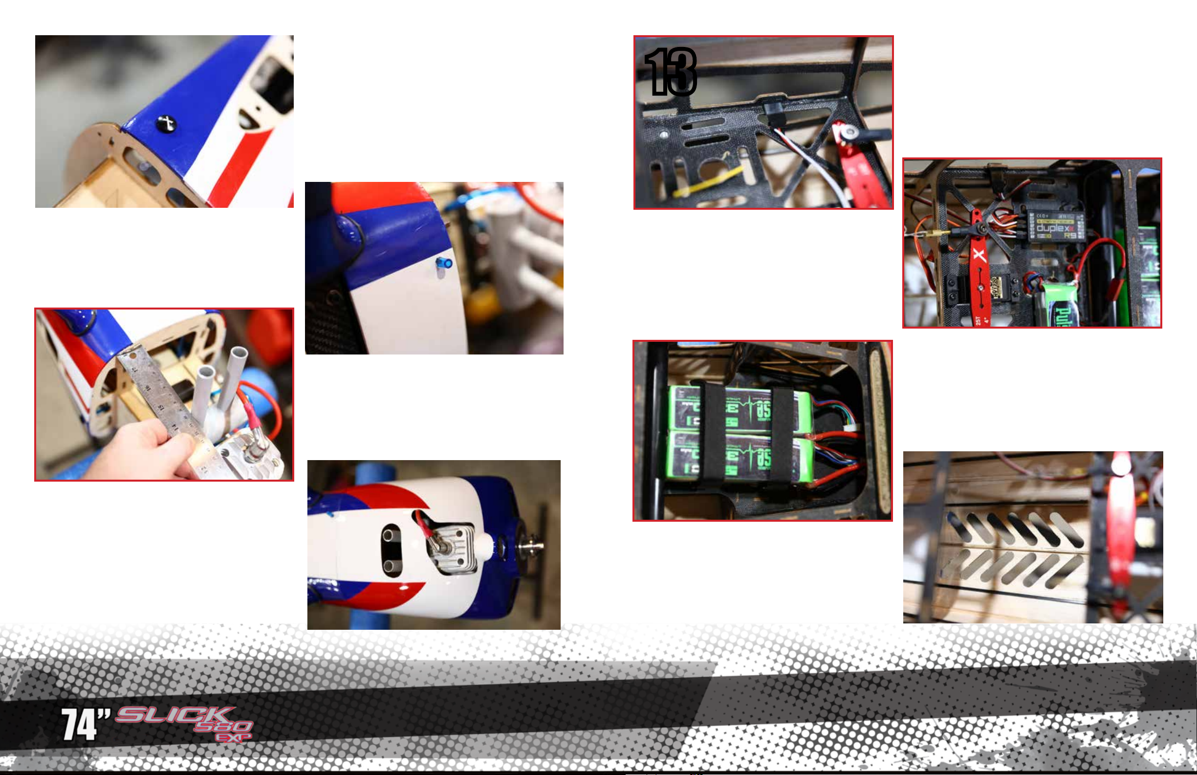
Install an Extreme Flight RC fuel dot as shown into
the fuselage side.
13
Use two6” (150mm) servo extensions for the aileron leads inside the fuselage. Your Slick includes
these mounting locations for the female servo connectors.
This is a typical overflow vent outlet location on the
bottom of the fuselage.
Working slowly, checking fit often, enlarge the openings until the cowl slides smoothly on and everything has clearance. Note that we have shown the
minimum amount of opening, which is fine for cool
weather. During the hot Summer, your engine may
need more cooling air
Mount your receiver, and tie all wires to prevent
vibration damage.
For electric power, use strong velcro straps to re-
strain the lipo battery packs as shown.
Measure the location of the exhaust outlets from
the firewall. Transfer this dimension to the bottom
of the cowl and cut the required openings. We use a
Dremel tool for this job - protect your eyes and lungs
from dust.
For electric power, open the vents on the bottom of
the fuselage as shown.
Page 13
14
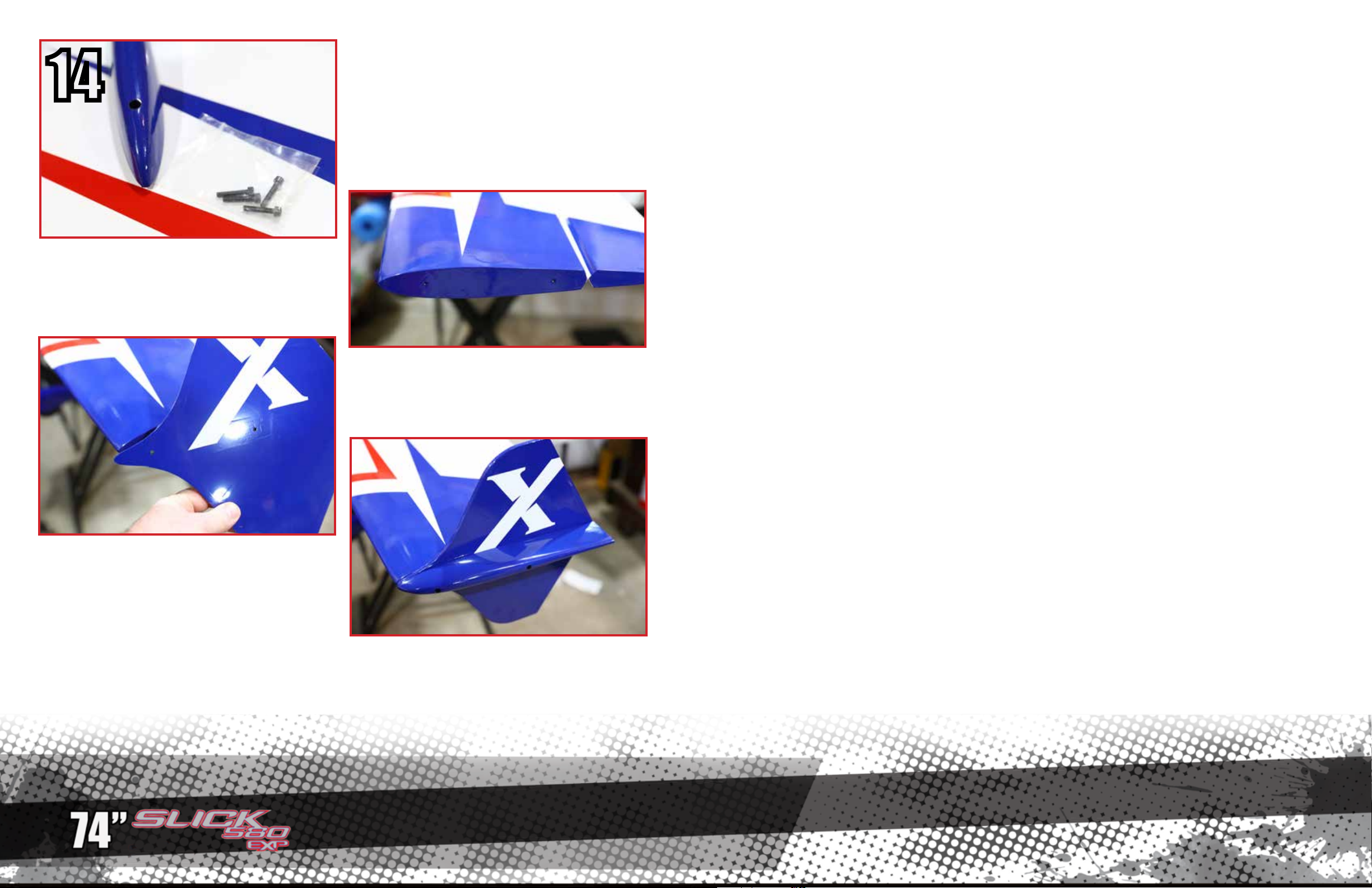
The wingtips of your Slick have 3mm nuts installed
to attach the wingtips/SFG’s. Open the covering as
shown to expose the nuts.
Locate the hardware for the wingtips and Side-Force
generators (SFG’s). Installing the wingtips and/or
SFG’s is purely optional. SFG’s increase stability in
3D flight and increase rudder authority. We recommend you try all combinations to determine which
you like best.
The holes in the wingtip match up to these holes in
the SFG’s and wingtips.
Set-up and trimming
Besides basic assembly, this is the most important part of preparing your airplane for flight. It can also be
the most time consuming, but once your plane is properly dialed in you will agree it was time well spent.
One of the most practical ways to check the CG on an aircraft this size is to insert the carbon fiber wing
tube into its sleeve in the fuselage and tie a length of string around the tube on each side of the fuselage,
forming a loop that you can pick the aircraft up with. Slide the wings into position, install the canopy and
pick up the plane with the string. The Slick should hang in a horizontal position on the center of the wing
tube, neither tail-down nor nose-down. Move your batteries and radio equipment to achieve this condition.
This will give you a safe starting place for the first flights.
One of the best ways to fine tune the CG for your aircraft is the 45 degree line test. Fly the aircraft in front
of you from left to right (or right to left if you prefer) at full throttle. Pull the aircraft into a 45 degree up line
and establish this line. Roll the aircraft inverted, neutralize the elevator and pay close attention to what the
plane does. Ideally the plane will continue on this line for several hundred feet before it starts to slowly level
o. If the airplane immediately drops the nose and dives toward the ground it is nose heavy. If it begins to
climb inverted toward the gear it is tail heavy. There is no need to have the Slick excessively tail heavy to
perform 3D maneuvers.
Control surface throws
I highly recommend that you purchase a throw meter that measures in degrees. There are several units
available commercially. These units are a great aid in set-up and definitely beat the “that looks about right”
method. For any type of precision flying, surfaces that travel equal distances are a must. The following control surface travels are what I use on my own Slick. These are a good starting point, but are by no means
the only way to set up the Slick. Start here and then adjust to fit your own preferences and style of flying.
Screw on the wingtips and SFG’s on as shown.
Because these parts need to be removed for transporting the aircraft, do not loctite these screws.
Elevator: 10-12 degrees low rate, 18-20% exponential
all you can get for high rate, 50-60% exponential
Aileron: 18-20 degrees low rate, 30-40% exponential
38-42 degreeshigh rate, 50-60% exponential
Rudder: 20 degrees low rate, 50% exponential
all you can get for high rate, 60-70% exponential.
Again, this is just a starting point. Adjust to your liking.
Thanks again for your purchase of the Extreme Flight RC 74” Slick 580 EXP
ARF. I hope you enjoy assembling and flying yours as much as I have mine.
See you at the flying field!
Chris Hinson
Page 14

Copyright 2017 Extreme Flight RC
 Loading...