


84” Turbo
1
Bushmaster
Copyright 2016 Extreme Flight

Please take a few moments to read this instruction manual before
2
beginning assembly. We have outlined a fast, clear and easy method
to assemble this aircraft and familiarizing yourself with this process
will aid in a quick, easy build.
Please read the following paragraph before beginning assembly of
your aircraft!
THIS IS NOT A TOY! Serious injury, destruction of property, or even
death may result from the misuse of this product. Extreme Flight RC
is providing you, the consumer with a very high quality model aircraft
component kit, from which you, the consumer, will assemble a flying
model. It is beyond our control to monitor the finished aircraft you
produce. Extreme Flight RC will in no way accept or assume
responsibility or liability for damages resulting from the use of this
user assembled product. This aircraft should be flown in accordance
to the AMA safety code. It is highly recommended that you join the
Academy of Model Aeronautics in order to be properly insured, and to
operate your model at AMA sanctioned flying fields only. If you are
not willing to accept ALL liability for the use of this product, please
return it to the place of purchase immediately.
Extreme Flight RC guarantees this kit to be free of defects in materials
and workmanship for a period of 30 DAYS from the date of purchase.
All warranty claims must be accompanied by the original dated
receipt. This warranty is extended to the original purchaser of the
aircraft kit only.
Extreme Flight RC in no way warranties its aircraft against flutter. We
have put these aircraft through the most grueling flight tests
imaginable and have not experienced any control surface flutter.
Proper servo selection and linkage set-up is absolutely essential.
Inadequate servos or improper linkage set up may result in flutter and
possibly the complete destruction of your aircraft. If you are not
experienced in this type of linkage set-up or have questions regarding
servo choices, please contact us at info@extremeflightrc.com or 770887-1794. It is your responsibility to ensure the airworthiness of your
model.

Congratulations on your purchase of the Legacy Aviation Turbo
3
Bushmaster! Our intention with the Legacy line of aircraft is to
provide unique sport-scale aircraft that are easy to assemble and fun
to fly. These models possess gentle flight characteristics for the
novice-to-intermediate sport flyer while also being capable of
advanced aerobatics for the more experienced pilot.
The Turbo Bushmaster is loosely based on the full scale Turbo
Beaver. The Turbo Beaver is a well known and loved aircraft among
bush pilots capable of STOL takeoffs and landings. The Turbo
Bushmaster is capable of these same maneuvers and so much more!
Big and light, the Bushmaster is as gentle and forgiving as any trainer
we've ever flown, making for a very enjoyable and relaxing flying
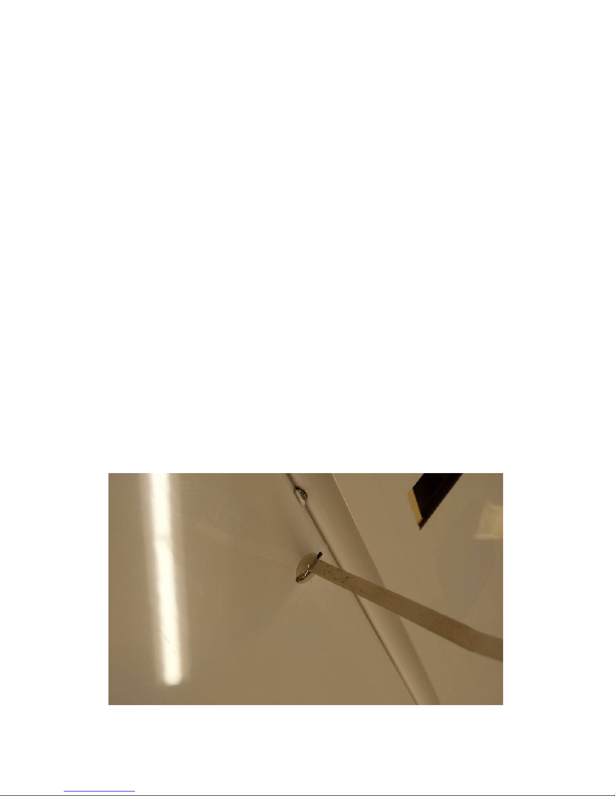
experience. Flip the rate switches and the model transforms into an
extremely capable aerobat! Experiment with the various flap mixes
that are possible and you open up a whole new envelope of high
lift/high drag maneuvers.

Let’s begin!
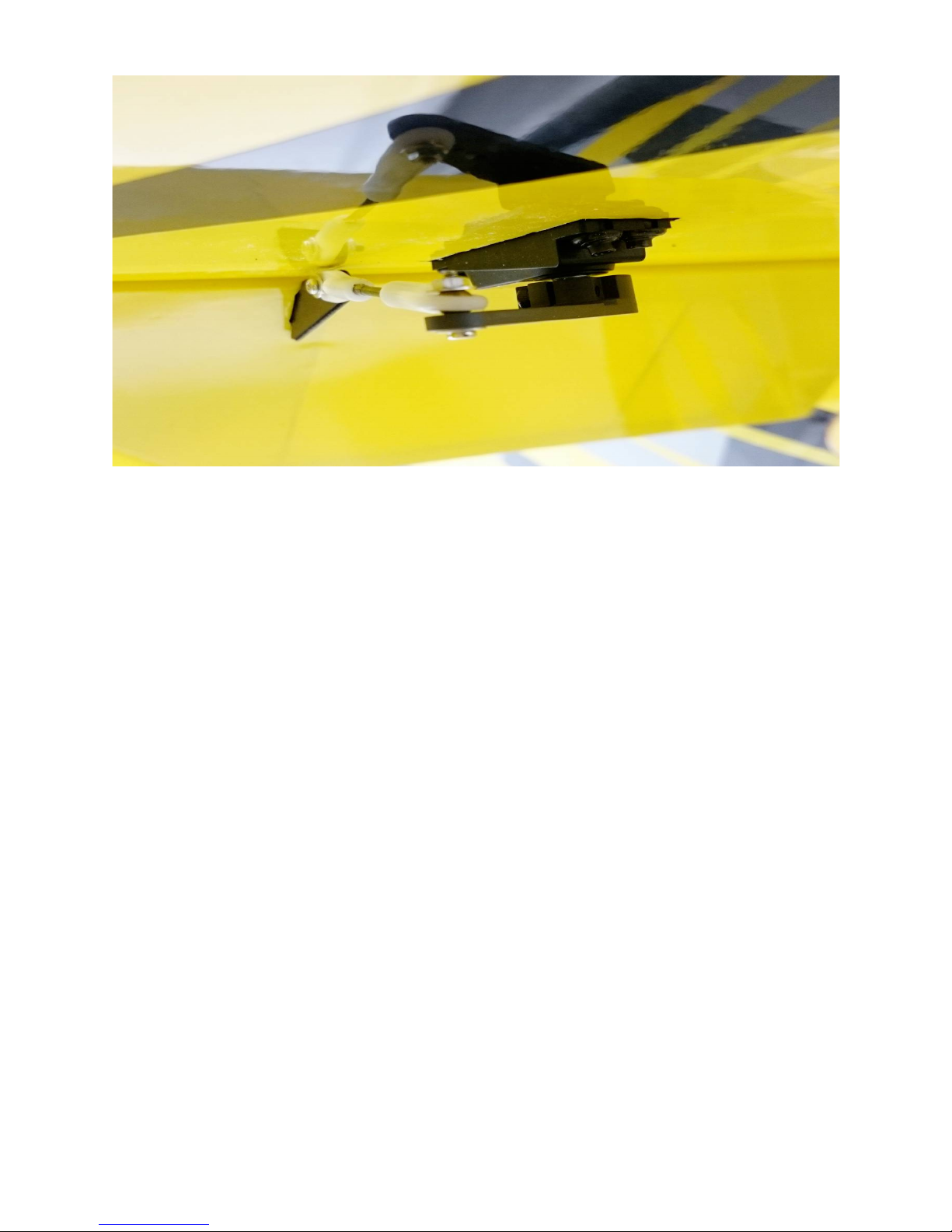
4
Wing Assembly
Wing Hardware:

1. Locate the 2 wing panels as well as the composite aileron and
5
flap control horns. Use sandpaper to scuff the portion of the
control horn that will be glued into the surface. For a more
finished look you may wish to paint your control horns before
installation. We used a black Sharpie to perform this task with
great results. Do not paint the portion of the control horn that
will glue into the control surface!
2. Using a soldering iron or a SHARP hobby knife, remove the
6
covering from the slots for the aileron and flap horns.
3. Dry fit the horns into their respective slots and trim any debris
from the slot until the control horn seats properly against the
control surface.
4. Apply 30-minute epoxy to the aileron and flap control horn slots
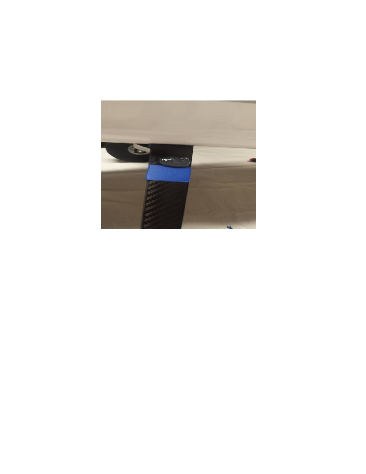
and to the scuffed area of the control horns. It may be helpful to
use a zip tie to push the epoxy into the slots.

5. Install the control horns into their respective slots and wipe
7
away any excess epoxy with a paper towel or cloth soaked with
denatured alcohol.
6. In these next steps we will install the hinges. Please take a few
moments to familiarize yourself with this process if you have not
installed hinge points before.
There are several ways to do this and several adhesives you can
use. We will describe the way that we do it, as this method has
proven itself over many years of model building. If you are new
to this type of hinging process, then I recommend that you
install a single hinge first just to acquaint yourself with this
method
Before starting you will need to gather a few items to aid you as
you proceed.
A. 30 Minute Epoxy
B. A short length of pushrod or small dowel.
C. A roll of paper towels
D. Denatured alcohol or Acetone
E. Hobby Knife
F. Silicon lubricant

7. Locate a wing panel and separate the control surfaces from the
8
main wing and remove the hinges.
8. Mix up a generous batch of epoxy and use a piece of pushrod or
dowel to apply the epoxy to the hinge hole.
9. Apply epoxy to the barbed section of the hinge on one side and
insert it into the hole until the center of the hinge is centered on the
hinge line. Using a paper towel soaked with acetone or denatured
alcohol wipe away any epoxy that has been squeezed out of the
hole.

10. Make sure the hinge can move freely and that the pin is aligned
9
properly before the epoxy sets! When you are satisfied with the
results set the surface aside so that the epoxy will pool around the
rear of the hinge. When you are comfortable with this process you
should be able to do one side of a surface per batch of epoxy.
Repeat the process to attach the surfaces to each wing. There
should be as little gap as possible while still allowing maximum
movement of the control surface.
11. As a final step before setting the wing aside to dry, do a final
cleaning of the hinge knuckles with a paper towel soaked with
denatured alcohol or acetone to remove any epoxy residue. If you
find any of the hinges are stiff after drying, apply a drop of acetone
to each hinge with a Q-tip and move the surface back and forth
several times to loosen it up. As a final step I typically apply a
couple drops of silicone lubricant to each hinge. This is available
at most home improvement and hardware stores. DO NOT USE A
PETROLEUM BASED LUBRICANT AS IT WILL DEGRADE THE
INTEGRITY OF THE NYLON HINGE!

12. You will need to attach a 12" servo extension to your aileron
10
servo to reach the wing root. The flap servo wire will reach the root
with no extension attached. Secure the extension to the servo lead
with heat shrink tubing or a wire keep.
13. Use the manufacturer supplied mounting hardware to install
the servos with the output shaft toward the LEADING EDGE of
the wing. Electronically center the servo and install 1.25" servo
arms onto the servo spline. The servo arms should be parallel
to the hinge line when centered. It is very important that you
use the same length servo arms for both flap and aileron
servos .

14. Thread the supplied ball links onto each end of the 4 pushrods.
11
Placing the pushrod into your electric drill and using it to thread
the pushrod into the ball link makes this task much easier. Be very
careful not to screw the pushrod in too far and damage the ball
link!
15. Use the supplied 2mm bolts, washers and nuts to affix the
pushrod to the servo arm and control horn. It is imperative to
attach the ball link to the bottom of the servo arm to achieve full
deflection.
16. Locate the wing fences and trail fit on the wing. Some
12
sanding may be required for best fit. While the fences are
temporarily installed on the wing use 2 pieces of painters tape to
mark their location on each side of the fence. This will aid in
alignment and prevent excess glue from getting on the covering.

17. Use 30 min epoxy to attach the fences. Wipe away any excess
13
epoxy with a paper towel soaked in acetone. Be sure to remove
the tape before the epoxy fully cures. Repeat this process for the
other wing panel.

Main Landing Gear Assembly and Installation
14
Tools Required for this step
12mm Wrench
8mm Wrench or Nut Driver
2.5mm Hex Driver
1.5mm Hex Driver
Thread locker
Painters tape
Sharp hobby knife
Welders adhesive or Goop
18. Locate the landing gear fairings and black rubber tubing. You
will need to slice the tubing lengthwise on one side. Use a sharp
hobby knife and starting at one end gently cut through only one
wall of the tubing being careful not to cut through the second side.
Once the tubing has been cut place it around the top of the landing
gear faring and secure it with CA

19. Locate the carbon landing gear, axles, wheels and fasteners
15
from the landing gear hardware package.

20. Attach the landing gear to the fuselage using the supplied
16
bolts and washers. The landing gear has a slight airfoil, make
sure that the thicker part of the gear is facing the nose of the
airframe.
21. Slide the gear fairings into place against the bottom of the
17
fuselage. Use a piece of painters to mark their location.
Remove the fairing and apply a thick bead of Goop to the carbon
gear just above the tape line. Slide the fairing back into place
and secure with tape until dry.

22. Locate the 2 axles, 2 locking nuts, 2 wheels, 4 wheel collars
18
and 2 washers and mount the wheels as shown.

Horizontal Stab and Elevator Assembly
19
Stab/elevator Hardware kit

23. Locate the horizontal stabilizer/elevator assembly. Turn it upside
20
down on the building table and remove the covering from the control
horn slot on the RIGHT side (This will be the Left side when installed).
Glue the control horn in place with 30 minute epoxy.
24. Insert the elevator section Upside-down and backwards into
the Stab/Elevator slot

21

25. Now insert the horizontal stabilizer and check that the hinge
22
holes match the holes in the elevator

26. Check that the horizontal stabilizer is centered and properly
23
aligned with the main wings. It is a good idea to use a tape
measure and triple check all measurements before gluing the
Stabilizer in place. Measure from a fixed point on the wings to the
tip of the Stabilizer on both sides. Adjust the stab until both sides
are the same. Take your time with this step as proper alignment is
critical.

27. Once satisfied with the alignment, glue the horizontal stab in
24
place by applying CA along the joint between the stab and the
fuse. Make sure to apply CA to the top and bottom of the stab.
28. Once the horizontal stab is glued in place, use the same
technique to install the elevator hinges and control horn that we
used for the aileron and flaps.

25

29. Locate the fences for the horizontal stab and attach them
26
with mediu
m CA. Make sure to confirm alignment with the
vertical stab.

30. Locate the lower keel. Note that the small extension piece
27
(top piece in picture) is to be used when building the airframe for
float flying only as it will occupy the space for the tailwheel.
31. Place the fuselage upside-down in a stand (the Extreme
Flight 4-in-1 stand works great!). Locate and remove the
covering from the 3 holes that the lower keel locks into.

32. Dry fit the lower keel in position and when happy with the fit,
28
use 30-minute epoxy to attach it to the fuselage. Use tape to
secure while drying. Be sure to check for proper alignment!
33. Attach an 18” servo extension to your elevator servo and
using the manufacturer supplied hardware install it with the
output shaft towards the rear of the fuselage. Assemble the
pushrod and install as shown in the picture.

Tailwheel Assembly
29
34. Gather the tools and parts required for this step
A. 1.5 mm Hex Driver
B. Phillips head screwdriver
C. Thread locker
D. Tail wheel
E. Tail wheel axle
F. Tail wheel Mounting Bracket
G. Wheel Collar
H. Tiller arm

35. Attach the wheel to the Axle with the supplied wheel collar.
30
NOTE: It is a good idea to file a small flat section on the axle for
the wheel collar set screw to mate up to.

36. Next install the carbon fiber mounting bracket and tiller arm.
31
Make sure to align the screw in the tiller arm with the flat spot on
the tailwheel shaft and use thread lock!

Mounting the Tailwheel Assembly
32
For this step you will need
A. Assembled Tailwheel
B. Small Phillips head screwdriver
C. Thin CA
D. 3 wood screws
E. 5/64” Drill bit and Drill
F. Tailwheel pushrod, Ball link and supplied hardware (not
pictured)

37. Locate the Tailwheel pushrod (29.5” and threaded on one
33
side) and insert it through the hole on the pilot’s upper left side
and into the guide tube, threaded end first.

38. Push the control rod carefully until you feel resistance,
34
locate the area where the control rod is trying to poke thru the
covering and use a sharp hobby knife or soldering iron to
remove the covering from this location. It is easiest to do this
with the fuselage upside down in a stand.
39. Place the tail wheel assembly up against the lower keel and
center it on the bottom of the fuselage . When you are happy
with the placement, use the holes in the tailwheel bracket as a
guide and drill three 5/64” holes. Add a drop of CA to each hole
and then attach the Tailwheel using the supplied wood screws.
Now would be a good time to thread the ball link onto the control
rod and attach it to the center hole of the tiller arm.

Vertical Stab/ Rudder Assembly
35
Rudder hardware kit

o To mount the vertical stab and rudder you will need to locate the
36
following:
A. Vertical stab and rudder assembly
B. Rear vertical stab wedge
C. Carbon fiber vertical stab tube
D. Rudder control horns
E. 4mm cap head screw
F. 30 min epoxy
G. 3mm Hex driver
T

40. Hinge the rudder using the same technique as the flaps and
37
ailerons.
41. Once the epoxy on the rudder hinges has cured, test fit the
rudder control horns. Make sure to scuff the bases of the control
horns. It may be necessary to trim the base of one of the control
horns to ensure that both horns fit properly into the control horn slot.

42. When satisfied with the fit of the control horns, mix up a small
38
batch of epoxy and install the rudder control horns.
43. Insert the carbon fiber vertical stab tube into the vertical stab/
rudder assembly. Then use your hobby knife or soldering iron to

remove the covering from the right side of the vertical stab to reveal
39
the mounting hole.
44. Slide the completed assembly into the vertical stab tube
socket and secure the stab to the fuselage with a 4mm cap head
screw. Don’t forget to use thread lock!

45. Deflect the rudder to one side and install the vertical stab
40
wedge. Wick in a bit of CA to hold it in place.

46. Locate the servo you will be using for the rudder. Using the
41
manufacturer supplied hardware mount the servo in the space
provided on the battery tray and electronically center it. Note
that the output shaft of the servo is towards the rear of the
airframe.
47. Locate the EZ-connector and mount it on the innermost
hole on the pilots left side of the servo arm. Put a drop of thin
CA on the bottom nut to prevent it from backing out.

48. Slide the Tailwheel pushrod into the EZ connector, center
42
the tailwheel and tighten the cap screw. Make sure you use
thread lock!
49. Next install the pull-pull cables and ball links. It is easiest to
build the rear half (rudder side) of the cables and install them

onto the rudder control horn, thread the cables thru the tubes in
43
the rear of the fuselage and then build the front end of the
cables on the servo side. To assemble the pull-pull linkage
follow these steps:
1. Slide one of the aluminum crimps onto the braided wire.
Insert the wire through the hole in the brass fitting and insert the
end of the wire back through the crimp. Loop the wire around
the crimp and insert again into the crimp. Carefully use a pair
of side cutters to crimp the wire in several places.
50. Follow this same method to assemble the linkages in the
forward part of the system that will attach to the servo arm. The
cables should cross in the fuselage for proper function. Adjust

the cables so that there is no slack but do not make them guitar
44
string tight as doing so can overstress the servo.
Windscreen Installation
51. Next we'll install the windscreen. You have the choice of gluing
the windscreen into place with a specialty glue like Pacer Formula 560

canopy glue or sewing it on with screws (not included). Also, a pair
45
of Lexan car body scissors will make this step much easier!
52. Locate the windscreen. Crudely trim it so that you can place it
into position.
53. Use blue tape to mark a cut line with the tape being placed inside
the line where you will trim the canopy. This will help to prevent the
canopy edges from splitting while being cut.
54. Test fit and trim as needed. Attach canopy with a thick bead of
canopy glue and tape in place with painters tape and allow to dry
overnight. Alternately you could sew the canopy in place with
multiple small screws. Photos of both attachment methods are
shown.

46

Motor and Electronic Speed Control Installation
47
55. Locate the following and prepare the motor for mounting
A. Motor (Torque 4016/500)
B. ESC (Airboss 80A)
C. Supplied Torque hardware kit with X mount and Bolt-on Prop
Adapter
D. 2.5mm Hex Driver
E. 3mm Hex driver
F. Small Phillips head screwdriver
G. Thread lock

56. Secure the prop adapter to the motor with supplied socket head
48
cap bolts using blue thread lock on each bolt.

57. Next slide the provided collar over the motor shaft and
49
secure in place with the set screw. Place a small drop of thread
lock on the threads of the set screw to prevent it from backing
out.
58. Attach the Supplied X mount with the 4 Philips head screws.
Again use a drop of thread lock on each screw.

59. Locate the 4mm black cap bolts and washers to attach the
50
assembled motor to the firewall.
60. Using a drop of thread lock on each bolt attach the motor to
the firewall.

61. Using a couple Zip ties and a scrap piece of foam mount the
51
ESC to the bottom of the motor box.
62. Connect the wires of the ESC and the motor and secure
them to the motor box with nylon cable ties.
63. Attach a 12” servo wire extension and a 8-10” battery
extension to the ESC and route them into the fuselage. There are

2 locations in the fuselage for mounting external ESC and BEC
52
switches. If you are going to use a switch go ahead and mount it
now.

Mounting the Cowl
53
64. Locate the following:
A. Cowl
B. Exhaust stacks
C. Contact adhesive or Epoxy
D. Sandpaper
E. Painters tape
F. Drill bit
G. Felt tip pen

65. Scuff the bottom of the exhaust stacks and the indentions
54
on the cowl where they will mount.

66. Using contact adhesive or epoxy glue the exhaust stacks to
55
the cowling and hold them in place with painter’s tape until the
glue is dry.

67. When the glue for the exhaust stacks is fully cured, tear 4
56
short pieces of painter’s tape and place each piece of tape on
the side of the fuselage so that each piece corresponds with one
of the 4 cowl mounting tabs. Use a felt tipped pen to mark the
location of the center of each mounting tab.
68. Slide the Cowl into position. Install the spinner onto the
motor shaft for reference and once satisfied with the cowl
position, roll the tape back into place and secure the cowl. Use a
1/16” drill bit to drill a hole at the location of the dot on each
piece of tape.

69. Remove the tape and cowl and add a drop of CA to each
57
hole. Mount the cowl with the 4 of the small wood screws
included with the kit.

70. Use a sharp hobby knife or soldering iron to remove the
58
covering over the air escape holes in the bottom of the
fuselage.
71. Mount your receiver as shown and tidy up the servo
extensions. Pictured mounted to the battery tray are 2 multiplug extensions to make plugging in your aileron/flap servo
leads easier. Affix a strip of Velcro to the battery tray and retain
your battery with a Velcro strap.

72. Install your prop and spinner.
59

73. Insert the carbon wing tube into the sleeve in the fuselage.
60
Slide the wings into position taking care to insert the servo
extensions into the fuselage. Secure the wings be inserting the
nylon wing bolts into the holes in the fuselage and threading
them into the blind nut in the wing root.
74. Attach the struts using the supplied 3mm cap head screws .
You may find it easiest to start with the wing attachment first.

This concludes the assembly process for the Turbo Bushmaster.
61
Preparing for flight!
With the wing and struts attached, place your battery on the
battery tray and pick up the Bushmaster by the wing tube. Shift
the battery until the plane balances on the tube. This is a safe
location to begin test flying. Adjust CG to your liking, then mark
the tray to know where to position the battery each flight.
Typically the plane balances with the battery centered on the
tray just forward of the wing tube as shown in the photo for step
number 71.
It is recommend you first fly the model in standard configuration
to get used to its flight characteristics before beginning to
experiment with flaps. When deploying flaps you will need to
add an elevator mix that compensates for the flaps and provides
a few degrees of down elevator. A comprehensive and detailed
setup document written by designer Cody Wojcik will cover
various mixes to experiment with and will be posted on the
Extreme Flight website.
Thanks so much for your business and we hope you enjoy flying
your Turbo Bushmaster as much as we have!
 Loading...