

Page 1
60" Laser ARF
Instruction Manual
Copyright 2013 Extreme Flight RC
12
Page 2

Please take a few moments to read this instruction manual before beginning assembly. We
have outlined a fast, clear and easy method to assemble this aircraft and familiarizing
yourself with this process will aid in a quick, easy build.
Please read the following paragraph before beginning assembly
of your aircraft!
THIS IS NOT A TOY! Serious injury, destruction of property, or even death may result
from the misuse of this product. Extreme Flight RC is providing you, the consumer, with
a very high quality model aircraft component kit, from which you, the consumer, will
assemble a flying model. It is beyond our control to monitor the finished aircraft you
produce. Extreme Flight RC will in no way accept or assume responsibility or liability for
damages resulting from the use of this user assembled product. This aircraft should be
flown in accordance with the AMA safety code. It is highly recommended that you join
the Academy of Model Aeronautics in order to be properly insured and operate your
model at AMA sanctioned flying fields only. If you are not willing to accept ALL liability
for the use of this product, please return it to the place of purchase immediately.
Extreme Flight RC, Ltd. guarantees this kit to be free of defects in materials and
workmanship for a period of 30 DAYS
must be accompanied by the original dated receipt. This warranty is extended to the
original purchaser of the aircraft kit only
aircraft against flutter. We have put these aircraft through the most grueling flight tests
imaginable and have not experienced any control surface flutter. Proper servo selection
and linkage set-up is absolutely essential. Inadequate servos or improper linkage set up
may result in flutter and possibly the complete destruction of your aircraft. If you are not
experienced in this type of linkage setup or have questions regarding servo choices, please
contact us at [email protected] or 770-887-1794. It is your
ensure the airworthiness of your model.
from the date of purchase. All warranty claims
. Extreme Flight RC in no way warranties its
responsibility to
Page 3

Congratulations on your purchase of the Extreme Flight RC 60 inch Laser EXP ARF!
I am a huge fan of the Laser 200 and the late airshow legend Leo Loudenslager. I always
knew that at some point Extreme Flight would have to produce a model of this iconic
airframe. My goal was to honor the unique legacy of Leo and his Laser while bringing the
model up to date to match the performance we have all come to expect from an Extreme
Flight EXP series aircraft.
One of the last modifications that Leo made to the Laser was to install a more streamlined
canopy. This canopy was installed on the Laser and flown by Leo prior to his tragic death
in a motorcycle accident. I much prefer the look of this canopy to the original and decided
to incorporate it into the Laser EXP design. In my research I found photos of the Laser
Z230, Laser 300 and 2000 that had all started incorporating much more streamlined
modern cowlings. I decided to incorporate a similar cowl into the Extreme Flight EXP
version as well. As such this model can't really be designated as any particular variant,
so I decided to simply call it the Laser EXP. Like all of the EXPs, the Laser excels at both
3D and precision maneuvers. It shares the long tail moment of the Extra and Edge which
gives it great stability in high speed precision maneuvers and it also features that famous
EXP elevator that allows for crazy pitch authority and great stability in high alpha
maneuvers. When the CG is properly set the Laser has minimal coupling and is a very
neutral aircraft.
The Laser EXP shares many of the attributes of the previous EXP airframes along with
some new features. Due to customer feedback we have changed the wing retention
method to make it much easier to attach the wings to the fuselage. The wings are also
slightly recessed into the fuselage sides which provide a much cleaner appearance and
insures the wings will appear flush with the fuselage sides. The Laser EXP incorporates
carbon fiber and G10 composites into the structure of the airframe, resulting in a
lightweight, yet twist free structure capable of handling extreme aerodynamic loads.
Carbon and G10 are used in high stress areas such as the landing gear mounting structure
and fuselage longerons to provide enormous strength and durability. A true piece of
carbon fiber art, the landing gear is airfoiled and has just enough "give" to cushion those
not so perfect landings. All control surfaces are pushrod driven with short linkages and
use ball links for slop free actuation with no binding. Optional Side Force Generators are
included and add to the already generous side area, increasing yaw axis authority and
adding stability in all angles of sideslip. Expertly painted fiberglass cowl and wheel pants
and 2 gorgeous high visibility Ultracote color schemes add the finishing touches and make
this an airplane that you will be proud to show up at the flying field with.
3
Page 4

Items needed for completion:
Masking tape.
Hobby knife with #11 blades.
Thin and medium CA. We highly recommend Mercury M5T thin and M100XF
medium formulas as well as the Mercury glue tips.
30 minute epoxy. Mercury Adhesives Epoxies have worked very well for us.
Blue Loctite.
Electric drill with an assortment of small drill bits.
Small flat head and Phillips head screw drivers.
Standard and needle nose pliers.
Side cutter.
Metric ball driver or allen key set.
Sanding block and sandpaper.
4 x METAL GEARED servos with a minimum of 76oz of torque. All flight testing
was performed with Hitec HS-7245MH.
Dubro Long Super Strength servo arm set. (Dubro part #670 for Futaba, #671 for
JR and #672 for Hitec).
2 x 6” Servos Extensions for the Ailerons.
2 x 24” Servo Extensions for the rudder and elevator servos
Torque 4016T/500 MKII Brushless Outrunner.
Airboss Elite 80 Amp ESC.
6S 3300-4000 mah LiPo battery.
16 x 7 prop.
The Ultracote colors used on the Laser are as follows:
Red color scheme
: True Red #HANU866, White #HANU870, Midnight Blue
#HANU885 and Gold #HANU879
Yellow/White/Blue color scheme
: Bright Yellow #HANU872, White #HANU870,
Midnight Blue #HANU885, Silver #HANU881
4
Page 5

Tips for Success:
1. Before starting assembly, take a few minutes to read the entire instruction manual
to familiarize yourself with the assembly process.
2. Please take a few minutes and go over all the seams on the aircraft with a covering
iron on a medium heat setting. Also, due to climate changes, wrinkles may develop
in the covering. These are easily removed with a little bit of heat. Use a 100%
cotton tee-shirt and your heat gun and heat the covering while gently rubbing the
covering onto the wood with the t-shirt. Be careful not to use too much heat as the
covering may shrink too much and begin to lift at the edges. Take your time, and a
beautiful, paint-like finish is attainable.
3. Apply a bead of Pacer Formula 560 Canopy Glue at the intersection of the plastic
canopy and its wooden frame.
4. Take a few minutes and apply CA to high stress areas such as servo mounting trays,
landing gear mounts, anti-rotation pins, and motor box joints.
5. By the time your aircraft arrives at your door step, it will have been handled by a lot
of people. Occasionally, there are small dings or imperfections on some of the
surfaces. An effective method to restore these imperfections to original condition is
to use a very fine tipped hypodermic needle and inject a drop of water under the
covering material and into the ding in the wood. Apply heat to the area with a
sealing iron and the imperfection will disappear. Deeper marks may require that
this process be repeated a couple of times to achieve the desired result, but you will
be surprised at how well this technique works.
6. Use a high quality epoxy for installing the composite control horns. We highly
recommend the new Mercury Adhesives 30 minute Epoxy or Pacer Z-poxy. We are
very pleased with the results and ease of application and cleanup of these products.
7. When applying decals, first clean the area where the decal will be applied with
alcohol. Mist the area lightly with Windex or Rapid Tack before applying the decal
which will allow you to properly position it, and then use a rubber squeegee to push
all of the liquid from under the decal. This will result in very few air pockets
trapped under the decal.
8. Take the time to properly balance and trim your aircraft and set up rates and
exponential values. Your flying experience will be greatly enhanced once your plane
is properly dialed in.
5
Page 6
Let's begin!
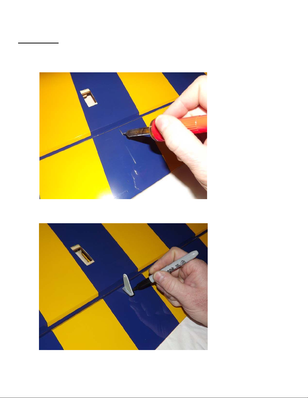
1. Locate the 2 wing panels as well as the composite aileron control horns and base
plates. Use a soldering iron or sharp hobby blade to remove the covering over the
slot for the aileron horn. Make sure you are doing this on the bottom of the aileron!
2. Insert the horn into the base plate and into the slot in the aileron. Use a fine
tipped felt marker to trace the base plate.
6
Page 7
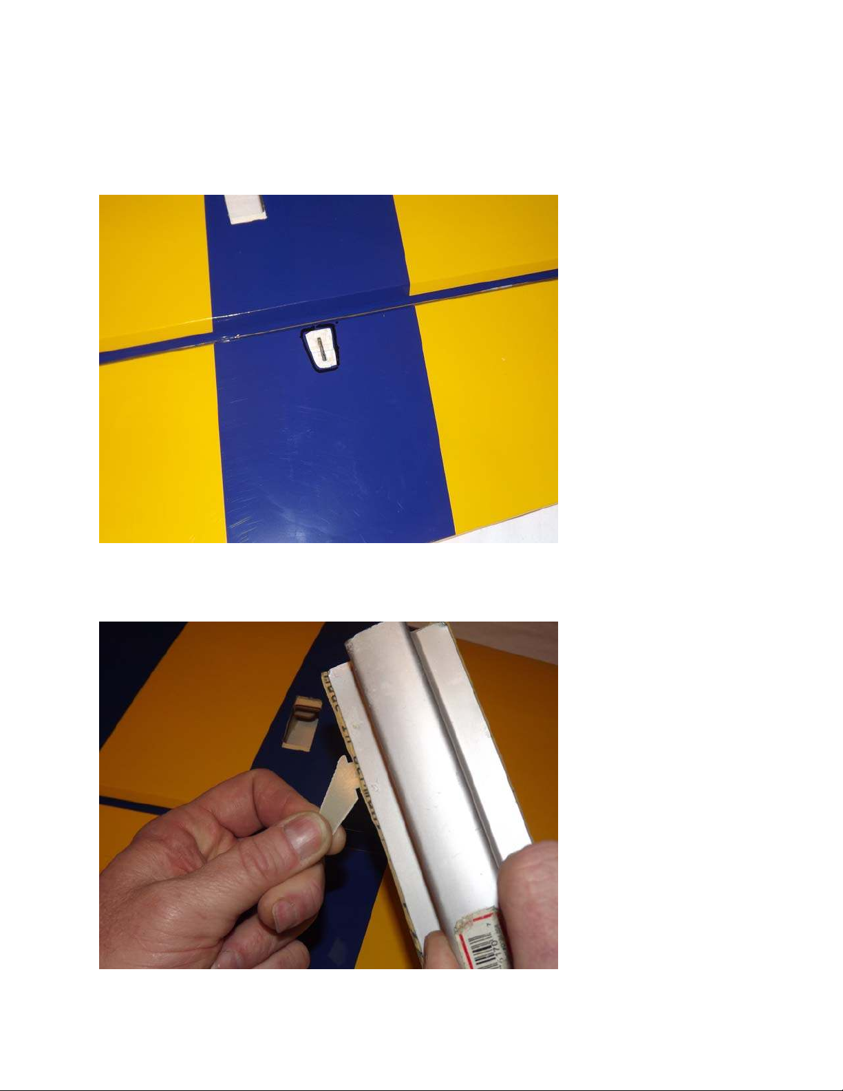
3. Remove the horn assembly and use a #11 blade to remove the covering from inside
the ink line you traced around the control horn base. Wipe away the ink line with a
cotton cloth or paper towel soaked in denatured alcohol.
4. Use sandpaper to scuff the portion of the horn that will be inserted into the aileron as
well as the bottom of the base plate.
7
Page 8
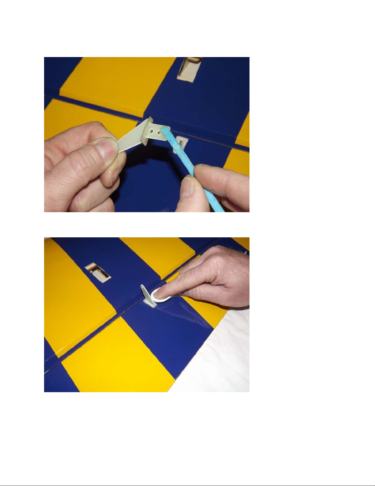
5. Insert the control horn into the base plate and apply 30 minute epoxy to the slot
in the aileron and the scuffed potion of the control horn that will insert into the
aileron. Use a zip tie to ensure the slot is completely filled with epoxy.
6. Install the aileron horn into the aileron slot and wipe away any excess epoxy with a
paper towel or cloth soaked with denatured alcohol.
8
Page 9
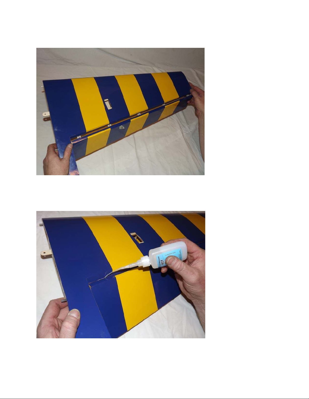
7. Remove the aileron from the wing to ensure all hinges are centered between the
wing and aileron. One way to ensure the hinges are centered is to fold them in half
and re-install into the aileron using the crease as a reference point.
8. Making sure the aileron is properly aligned between the wing root and wing tip,
hold the aileron fully deflected and apply a drop of thin CA to each hinge. Flip the
wing over and repeat.
9
Page 10
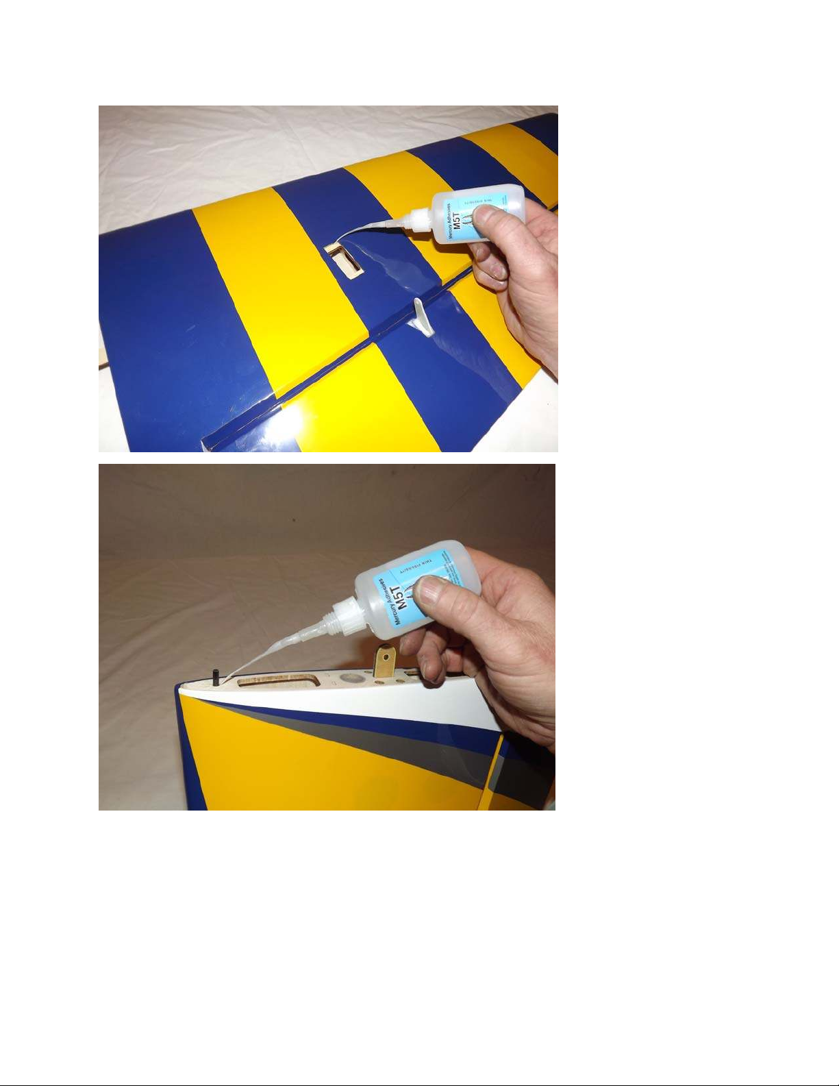
9. Before installing the aileron servo, take a minute and apply some CA to the servo
tray and the anti-rotation pins.
10. Before moving to the next step, it would be a good time to seal the hinge gap
with a strip of Ultracote or Blenderm tape. Be sure to fully deflect the control
surface when sealing the gap to allow for full deflection once the gap is sealed. Also,
take a few minutes to go over all of the seams in the covering with a sealing iron on a
medium heat setting, paying special attention to stripe edges and ends.
10
Page 11
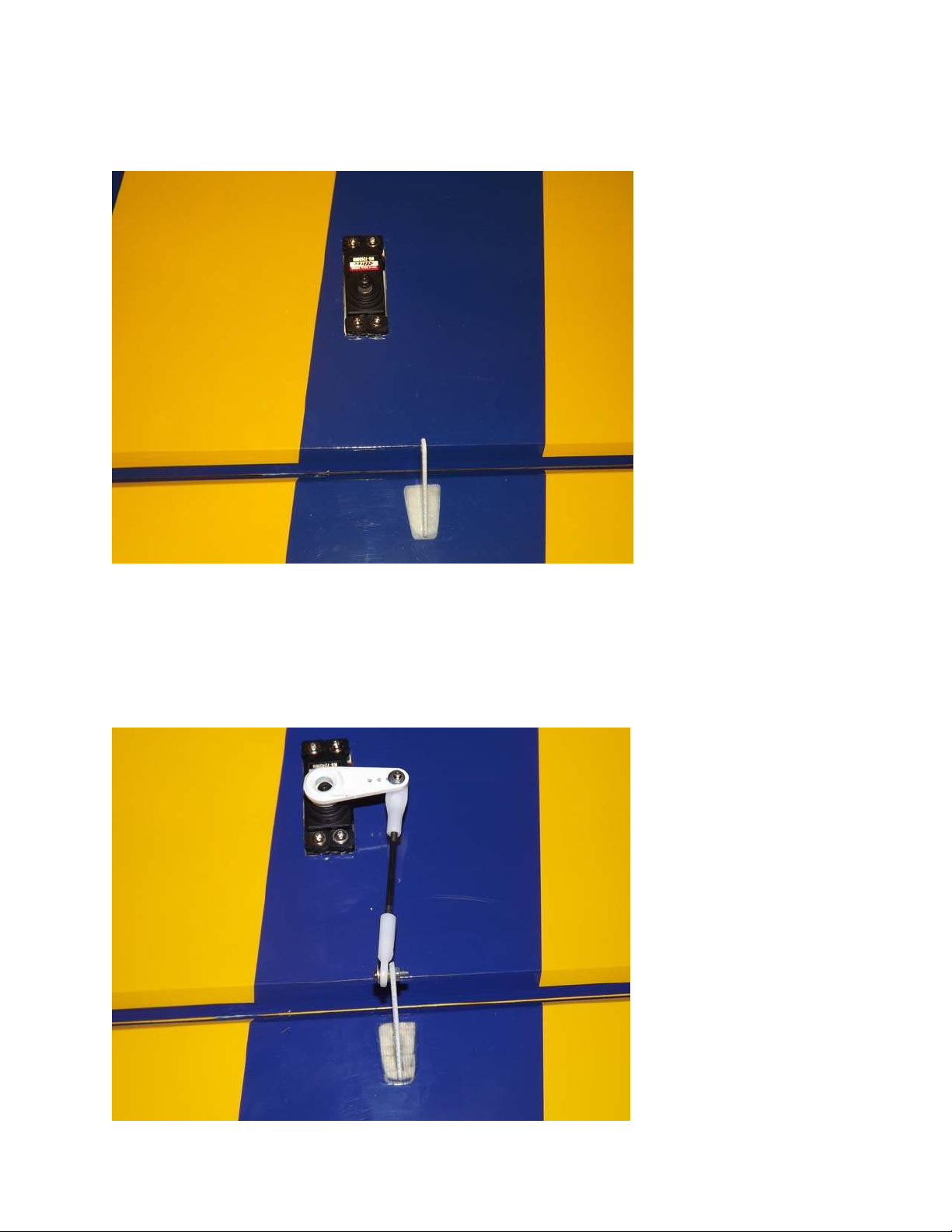
11. Attach a 6” servo extension to the servo and secure with thread or heat shrink
tubing. Use the manufacturer supplied mounting hardware to install the servo with
the output shaft toward the trailing edge of the wing. Electronically center the servo
and install the second longest servo arm from the Dubro servo arm kit.
12. Locate 2 of the short threaded metal pushrods and 4 ball links along with 4 x 2mm
screws, nuts and washers. Thread the ball links onto each end of the pushrods and
secure to the bottom of the servo arm and to the control horn as shown in the picture
below. Remember to use Loctite on all nuts. Repeat this process for the other wing
half. Clean the wing panels with a soft cloth and put them away in their wing bags.
11
Page 12
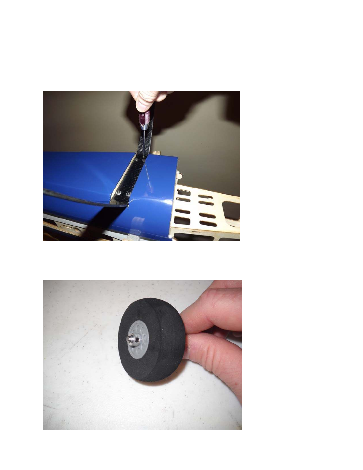
Fuselage Assembly
13. Locate the carbon fiber landing gear and secure the landing gear to the fuselage
by inserting the 3mm bolt into a washer, through the carbon fiber gear and into the
pre-installed blind nuts in the fuselage. Make sure to use a drop of blue Loctite on
each bolt to prevent them from backing out. Note the LG has a tapered edge and a
straight edge; make sure the straight edge faces the front of the fuse.
14. Locate the 2 axles, 2 locking nuts, 2 wheels, 2 wheel collars and 2 wheel pants.
Place the wheel on the axel and secure with the wheel collar.
12
Page 13
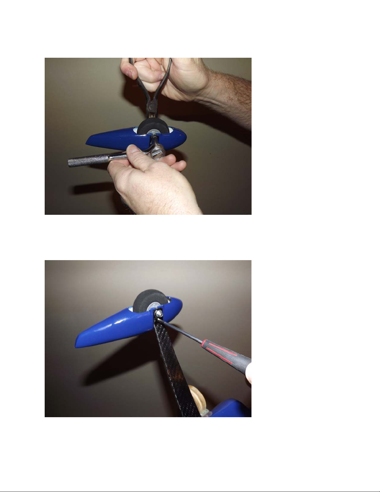
15. Place the threaded portion of the axle through the hole in the landing gear and
attach the lock nut and washer onto the axle. Slide the wheel pant into position over
the axle and tighten the nut, making sure the wheel pant is positioned properly.
th
16. When satisfied with the position of the wheel pant, drill a 1/16
hole through the
wheel pant at the location of the hole in the landing gear and secure with a wood
screw. Repeat this process for the remaining wheel pant.
13
Page 14
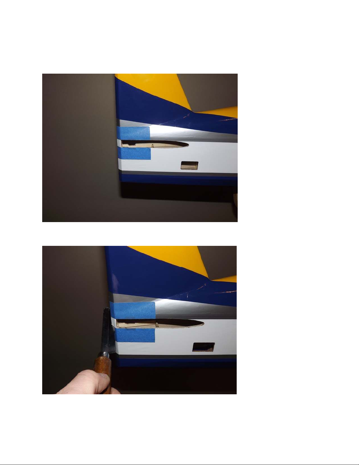
17. Before installing the horizontal stab you will need to remove the piece of balsa at
the rear of the stab slot. The factory leaves this piece intact so that the rear of the
fuselage will remain true during the covering process and during transit. First place a
couple strips of masking tape on the fuselage to give you a guide to cut by and to
prevent the Ultracote covering from tearing.
18. Use a razor saw to carefully make the cut, then sand smooth.
14
Page 15
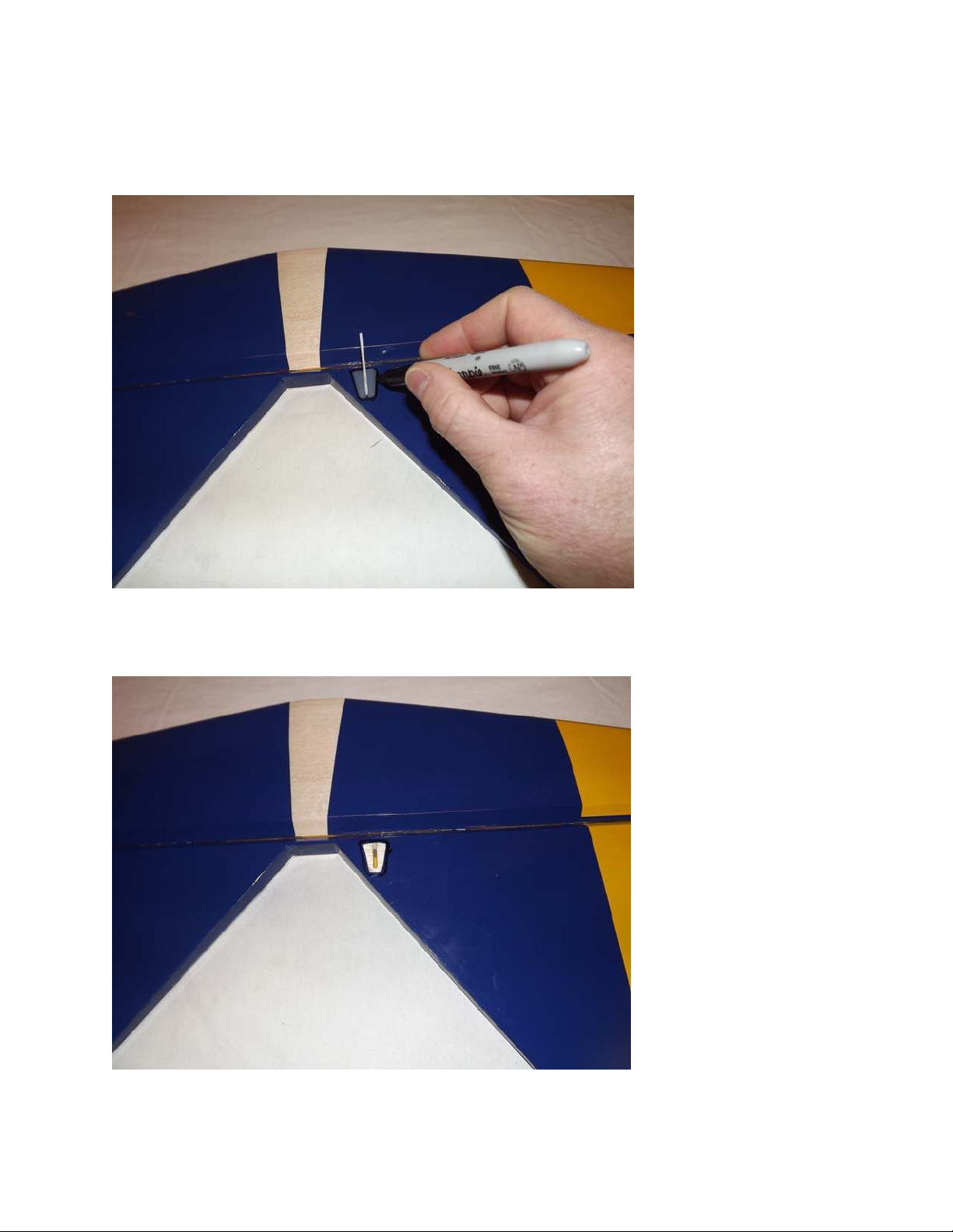
19. Locate the horizontal stabilizer/elevator assembly. Turn it upside down on your
building table and remove the covering over the right slot on the bottom of the elevator
where the elevator control horn will be installed. Using the same process as with the
ailerons, insert the horn into the base plate and into the slot. Trace around the base
plate with a fine tipped marker.
20. Use a sharp hobby knife to remove the covering 1/16" inside the line you traced.
Wipe away the ink line with a cotton cloth or paper towel soaked in denatured alcohol.
15
Page 16
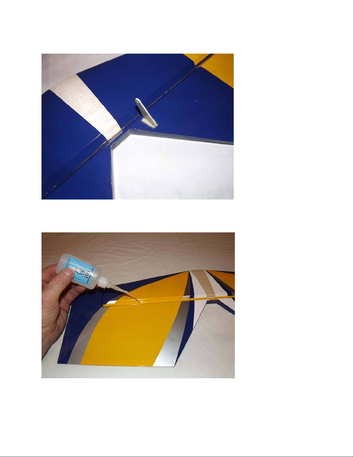
21.Scuff the portion of the control horn that will insert into the elevator as well as the
bottom of the base plate with sandpaper. Secure the control horn to the elevator with
epoxy just as you did with the aileron horns.
22. Slide the elevator onto the hinges in the stabilizer making sure the hinges are
centered in the hinge gap and secure with thin CA.
23. Before moving to the next step, it would be a good time to seal the hinge gap with
a strip of Ultracote or Blenderm tape. Also, take a few minutes to go over all of the
seams in the covering with a sealing iron on a medium heat setting, paying special
attention to stripe edges and ends.
16
Page 17
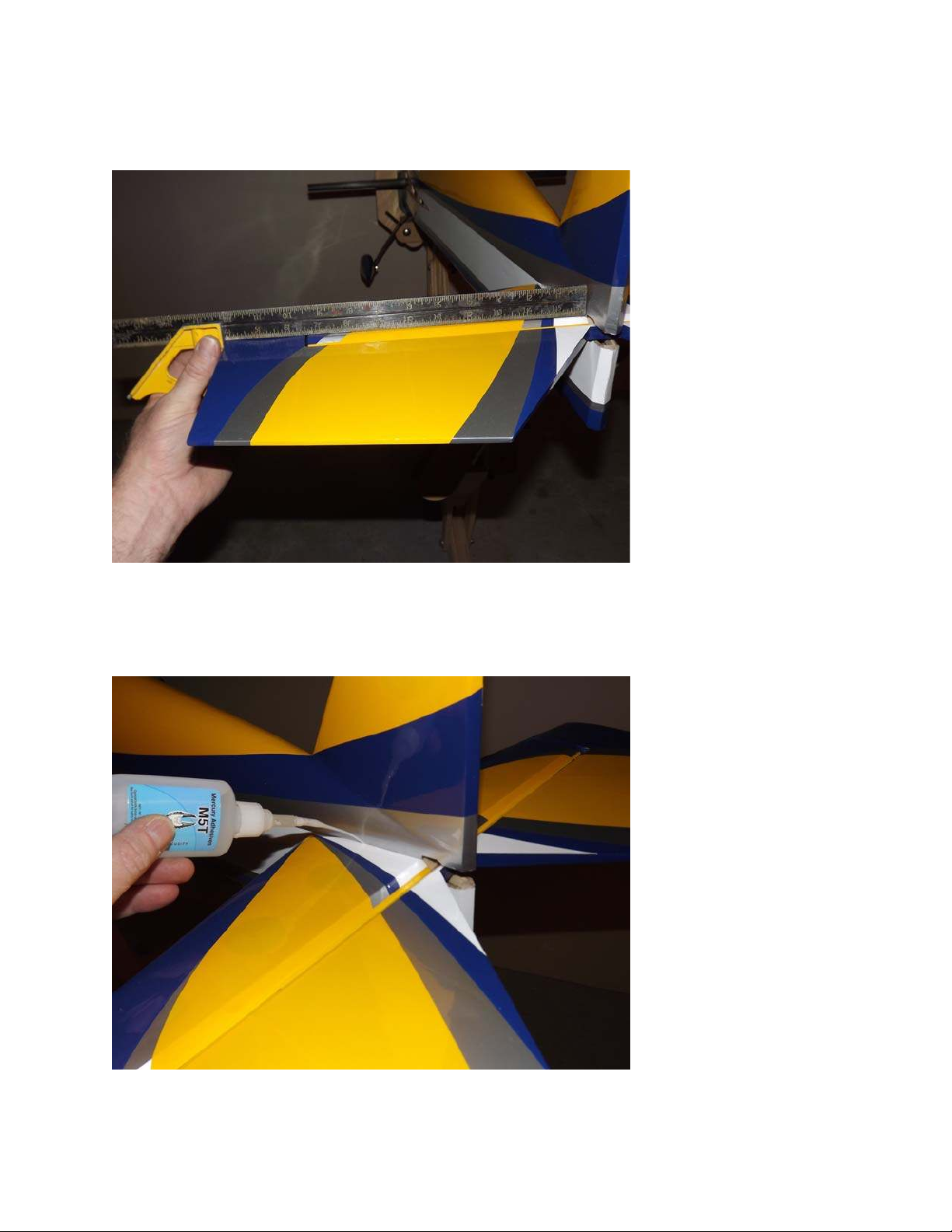
24. Insert the stabilizer into its slot and the carbon fiber wing tube into the fiberglass
sleeve. Use a ruler to insure that the stabilizer is centered in its slot and compare the
stabilizer to the wing tube to make sure it is properly aligned. Sand or shim the slot if
necessary to ensure proper alignment.
25. Once satisfied with the alignment, glue the horizontal stab in place by applying CA
along the joint between the stab and fuse. Make sure to apply CA to the top and bottom
of the stab, being careful not to get CA on the covering.
17
Page 18
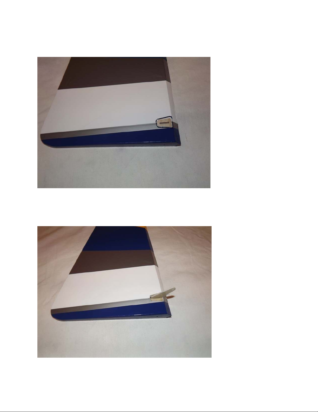
26. Remove the covering over the slot on the right side of the rudder. Follow the same
procedure as with the ailerons, Use a sharp hobby knife to remove the covering 1/16"
inside the line you traced. Wipe away the ink line with a cotton cloth or paper towel
soaked in denatured alcohol.
27. Scuff the portion of the control horn that will insert into the ruder as well as the
bottom of the base plate with sandpaper. Secure the control horn to the rudder with
epoxy just as you did with the aileron horns.
18
Page 19
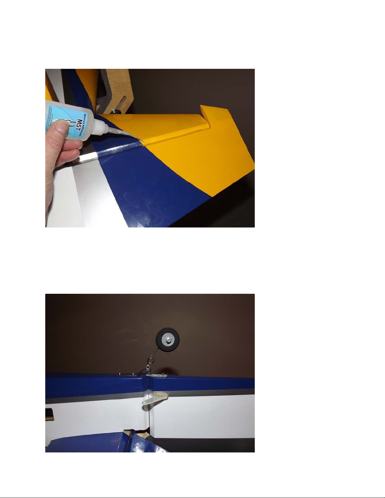
28. Slide the rudder onto the hinges in the vertical stab, making sure the hinges are
centered between the rudder and stab. Also, make sure the rudder is flush with the top
and bottom of the stab. Once satisfied, glue the hinges in place with thin CA making
sure the rudder is fully deflected.
29. Locate the carbon fiber tailwheel assembly in the hardware package. Secure the
tailwheel bracket to the bottom rear of the fuselage with the provided wood screws,
making sure the pivot point of the assembly is over the hinge line of the rudder. Secure
the tiller using the provided screw, but do not over tighten as the tiller should be able to
move on the screw as the rudder is deflected.
19
Page 20
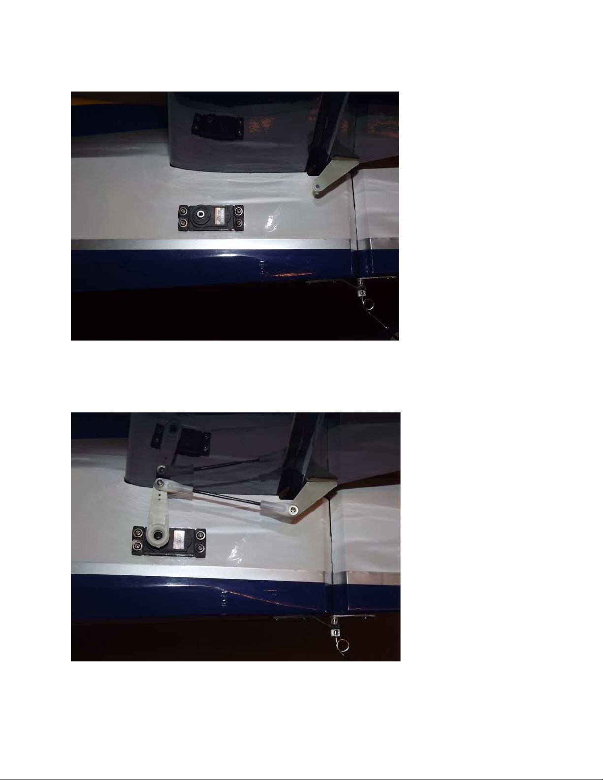
30. Attach a 24” servo extension to the elevator servo and secure with thread or heat
shrink tubing. Use the hardware provided with the servos to install the elevator servo
on the left side of the fuse with the output shaft toward the front of the aircraft.
31. Electronically center the servo and install the longest servo arm from the Dubro
servo arm kit. Locate the middle sized pushrod and 2 ball links and assemble the
pushrod linkage as shown in the picture below. Remember to use Loctite on all nuts.
20
Page 21
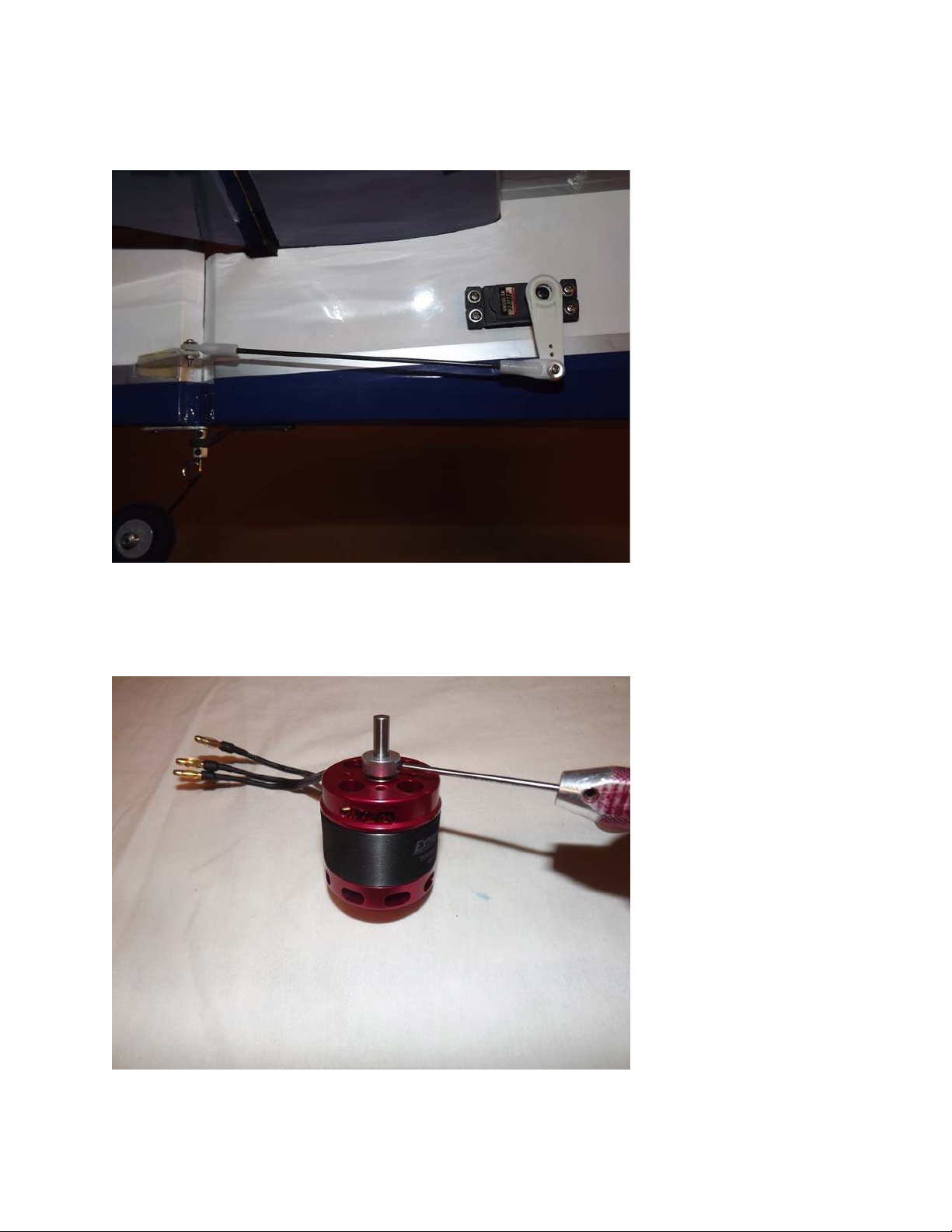
32.Using the same procedure as with the elevator, install the rudder servo on the right
side of the fuse with the output shaft toward the front of the aircraft. Locate the long
pushrod and 2 ball links and assemble the pushrod linkage as shown in the picture
below. Remember to use Loctite on all nuts.
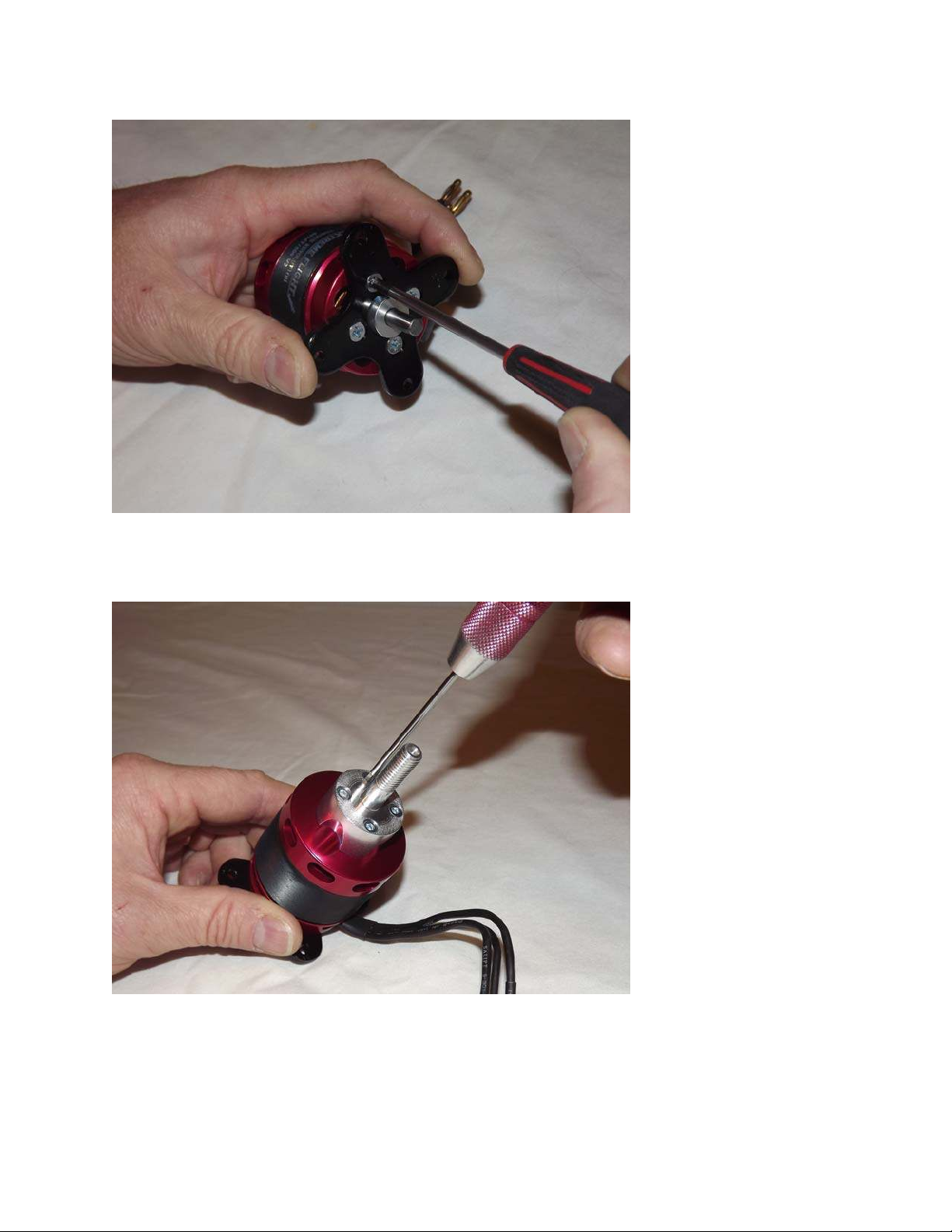
33. Next prepare the Torque outrunner motor for mounting. First, slide the provided
collar over the motor shaft and secure in place with the set screw. Place a drop of blue
Loctite on the threads of the set screw so that it will not back out.
21
Page 22
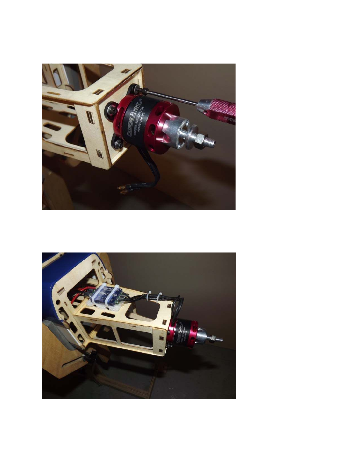
34. Next, secure the radial mount to the motor using the provided short Phillip's head
machine screws. Again be sure to use a drop of blue Loctite on each screw.
35. Secure the prop adapter using the 4 socket head cap bolts. Blue Loctite should be
applied to each bolt.
22
Page 23
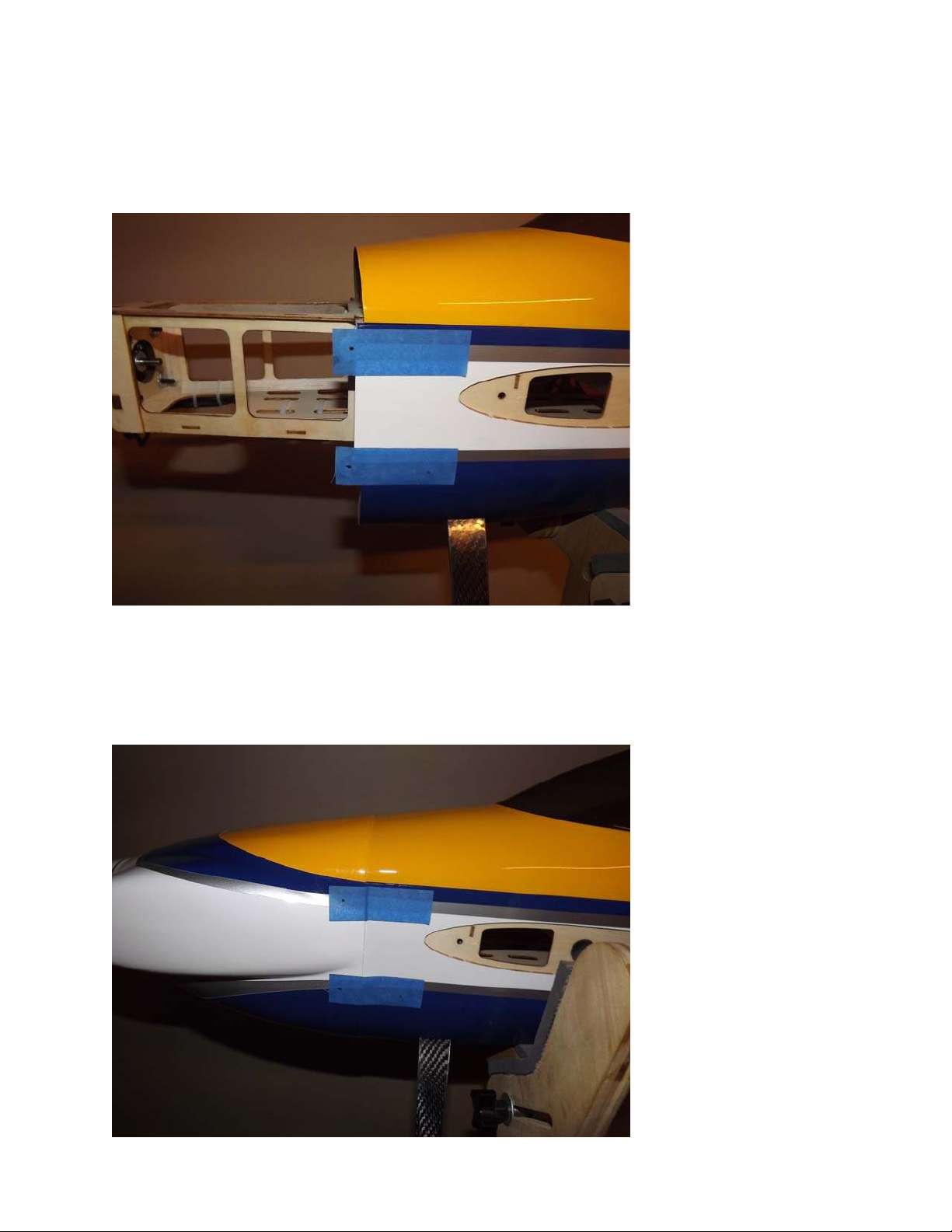
36. Mount the Torque motor using the supplied 4mm black socket head cap bolts
and washers. The bolts are to be inserted into the blind nuts which are pre-installed
in the motor mount plate. Be sure to put a drop of blue Loctite onto each bolt to
prevent them from backing out. Also take time to add CA to all motor box joints!
37. Install the ESC to the bottom of the motor box using a zip tie or Velcro to secure
the ESC. Connect the wires of the ESC and motor together and secure with a zip tie
as shown in the picture below.
23
Page 24
Mounting the Cowl
38. Tear 4 short pieces of blue painters tape from a roll. Place each piece of tape on
the side of the fuselage so that each piece corresponds with one of the 4 cowl
mounting tabs. Use a fine tipped marker to mark the location of the center of each
mounting tab.
39. Roll the tape back and slide the cowl into position. Install the spinner onto the
motor shaft for reference and once satisfied with the cowl position roll the tape back
into place and secure the cowl. Use a 1/16" drill bit to drill a hole at the location of
the dot on each piece of tape.
24
Page 25
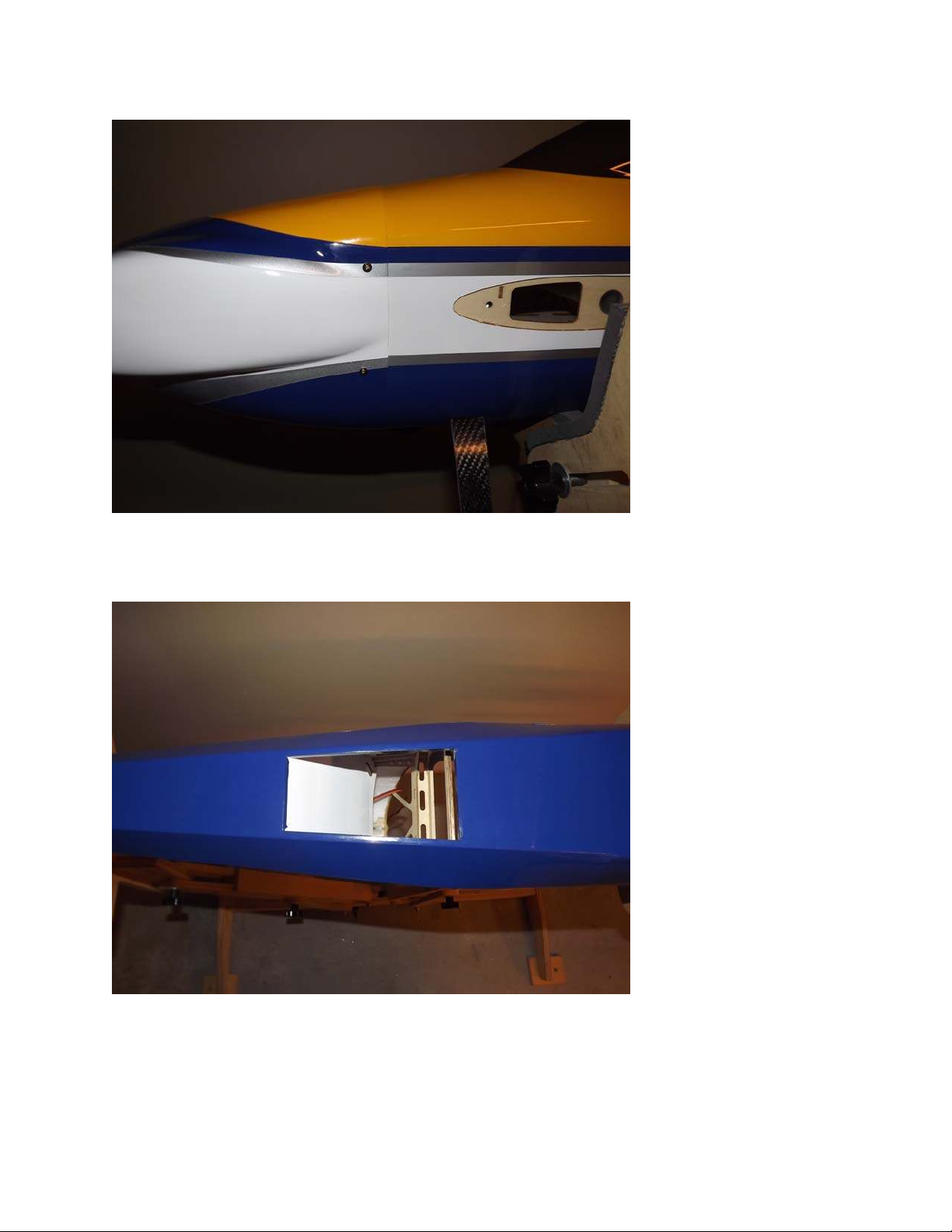
40. Remove the tape and secure the cowl with 4 of the included small wood screws
that have the large heads.
41. Use a sharp hobby knife to remove the covering from the opening in the bottom
of the fuselage under the canopy to allow cooling air to exit the fuselage.
25
Page 26
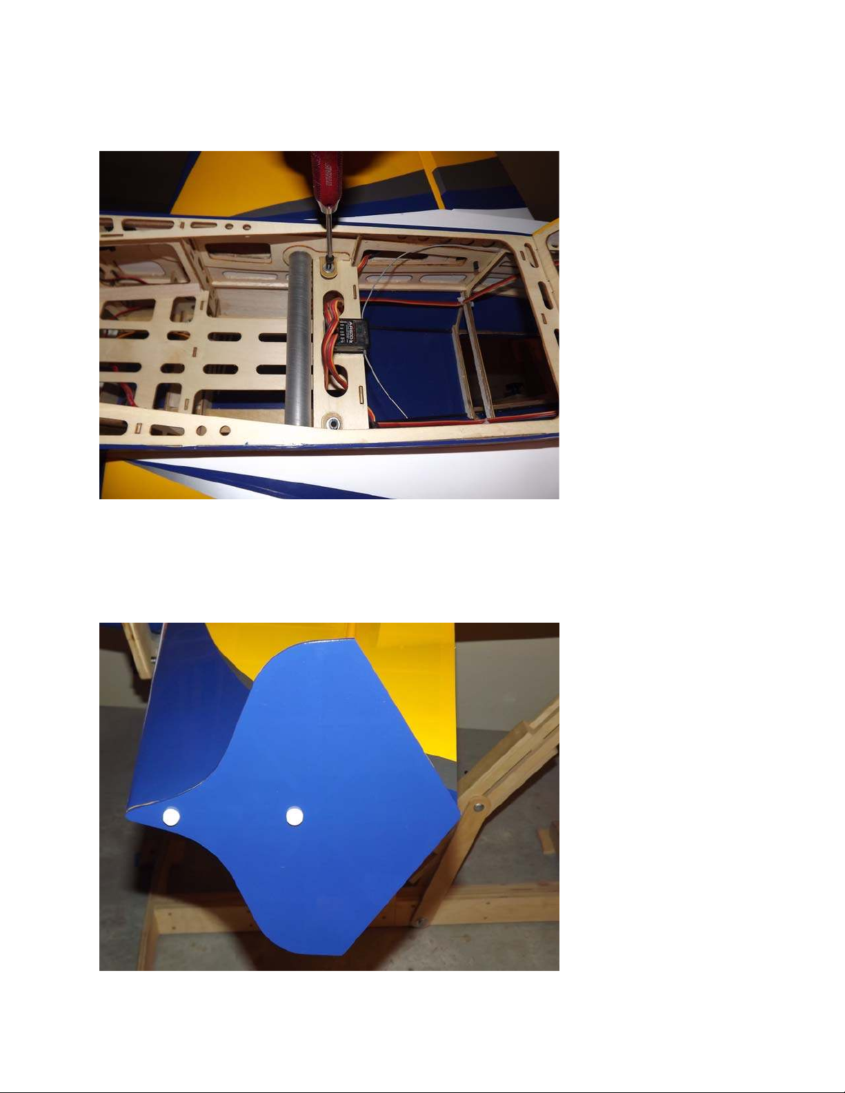
42. The wings are retained by inserting a 4MM bolt and washer through the tabs
each wing at the side of the fuse just in front of the wing tube. Make sure the wings
are pushed all the way in so the holes in the tab and fuse line up. Take care not to
cross thread the bolts.
43. If using the included Side Force Generators now is the time to mount them.
There are 2 clear spacers the shape of the wing tip that are to be placed between the
wing tip and SFG to prevent them from rubbing against the aileron. Each SFG
mounts using 2 X 3mm thumb screws.
2627
Page 27

Set-up and Trimming
The CG range for the Laser EXP starts at the front of the wing tube and extends to the
rear of the wing tube. There is plenty of room on the battery tray to move your battery to
achieve this CG location. Depending on your flying style you can adjust the position of the
battery to alter the CG to accommodate your preferences.
I highly recommend fine tuning your CG using the 45 degree line test. Fly the aircraft
from left to right or right to left, whichever direction you are more comfortable with at 3/4
to full throttle. Pull the aircraft to a 45 degree up line and establish this line and
immediately roll the aircraft inverted. Establish this line and let go of the elevator stick.
Ideally the aircraft will continue to track on that 45 degree line for several hundred feet
before slowly starting to level off. Adjust the position of your battery to achieve this flight
condition. Once satisfied with the location of your CG scribe a mark on the battery tray so
that you can position the battery in the same location each flight and achieve the same feel
and flight characteristics each flight.
I also highly recommend taking the time to properly set up your rates and exponential
settings. Setting up low rates for precision maneuvers and high rates for aggressive
aerobatics and 3D flight will allow you to experience the best attributes of the Laser EXP
or any aircraft for that matter. Here are some suggested rates to get started with. These
are the rates and exponential values I feel comfortable with. They may feel awkward to
you and if so please adjust to your taste.
Elevator: Low rate-8-10 degrees; 15-20% Exponential
3D rate-45-50 degrees; 40-50% Exponential
Insane tumble rate: As much as possible! 65-70% Exponential
Rudder: Low rate-20 degrees; 45-50% Exponential
3D rate- As much as possible; 60-70% Exponential
Aileron: Low rate-15-20%; 40-45% Exponential
3D rate- As much as possible; 50-60% Exponential
Page 28
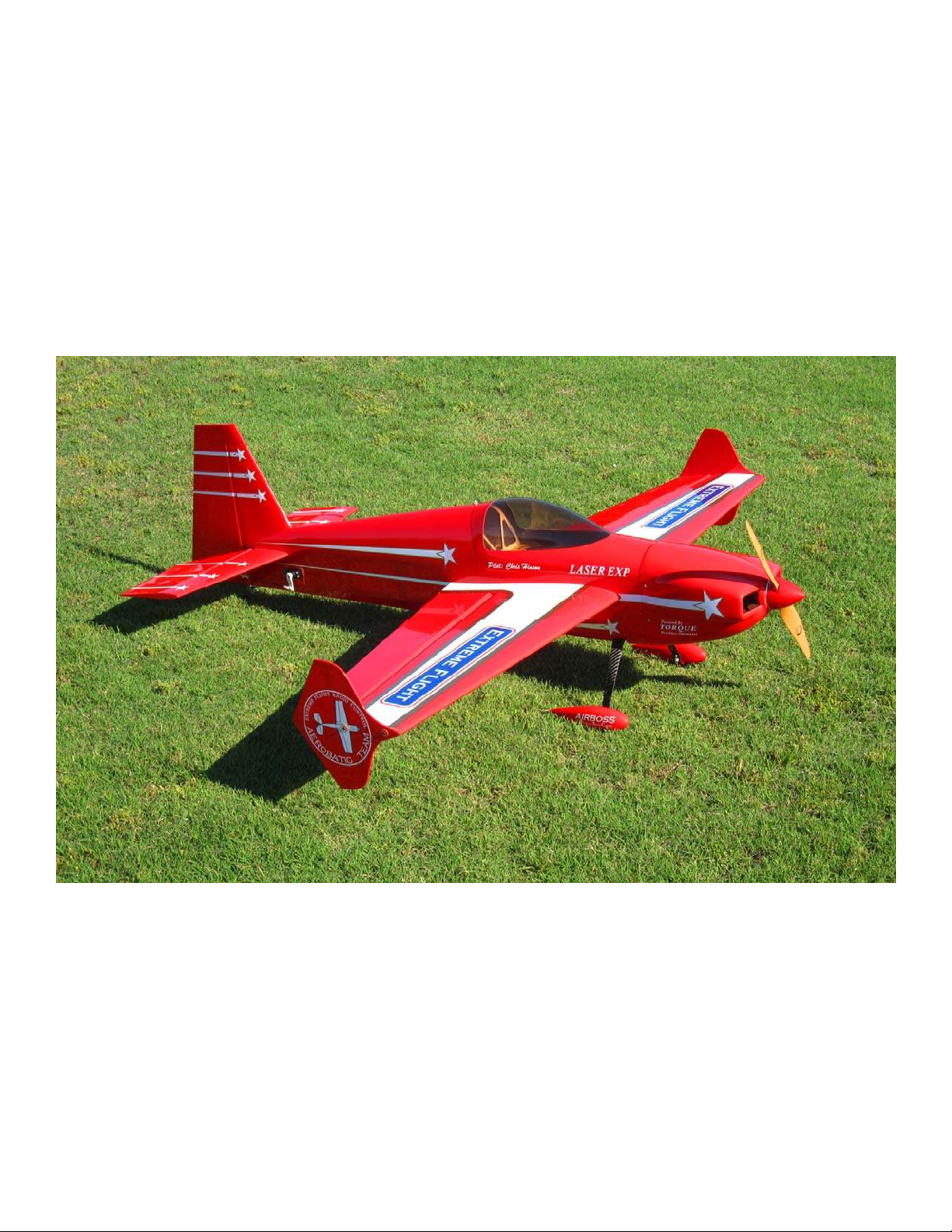
This completes the assembly of the 60 inch Laser. As a final step clean the entire aircraft
with glass cleaner, then apply a coat of spray-on wax and buff the finish to a high gloss
with a microfiber cloth. My favorite product for this is Eagle One Wet Wax AS-U-DRY,
available in the automotive section of most Wal-Marts, K-marts, Sears, Targets, etc.
People often ask me at trade shows how I get the planes to look so shiny, this is my secret.
You may wish to apply all of your graphics before applying the coat of wax.
Thanks again for your purchase of the Extreme Flight RC 60 inch Laser ARF. I hope you
enjoy assembling and flying yours as much as I have mine.
See you at the flying field!
Chris Hinson
Extreme Flight RC
28
 Loading...