

Extreme Flight focke-wulf FW-190A Assembly Manual
1
Focke-Wulf
FW-190a
Copyright 2016 Extreme Flight RC
2
Congratulations on your purchase of the AcesHigh Focke-Wulf 190A!
The FW-190 was a backbone of the German Luftwaffe, BMW 801 twin-row radial powered, multi-role fighter. A favorite
of many, it was effectively flown by some of the most successful fighter aces. It wasn’t until the arrival of the Spitfire
that the 190 was challenged for air superiority.
AcesHigh have worked hard to create a model that pays great tribute to the performance of the real thing. As part of the
Extreme Flight family, we have combined the highest level of aircraft manufacture with new technology, and the results
are fantastic. Months of research and effort to create a realistic result without the typical weight problems that go along
with detail. In making the model look real, our objective was to recreate the full size plane as it was in operation. Those
aircraft worked hard, and got very dirty in the process. The details on the scheme are as if the full scale aircraft was
wheeled into a photo booth... there are no pin-stripe panel lines and dots for rivets, because panels aren’t pin-stripes,
and rivets were rivets. This isn’t the “brand new” looking warbird that is typically seen… congratulations on owning the
first ARF that comes dirty out of the box!
We hope that you enjoy the build, love the flying, and appreciate just sitting and looking at it when she’s just sitting
there… waiting for the next sortie.
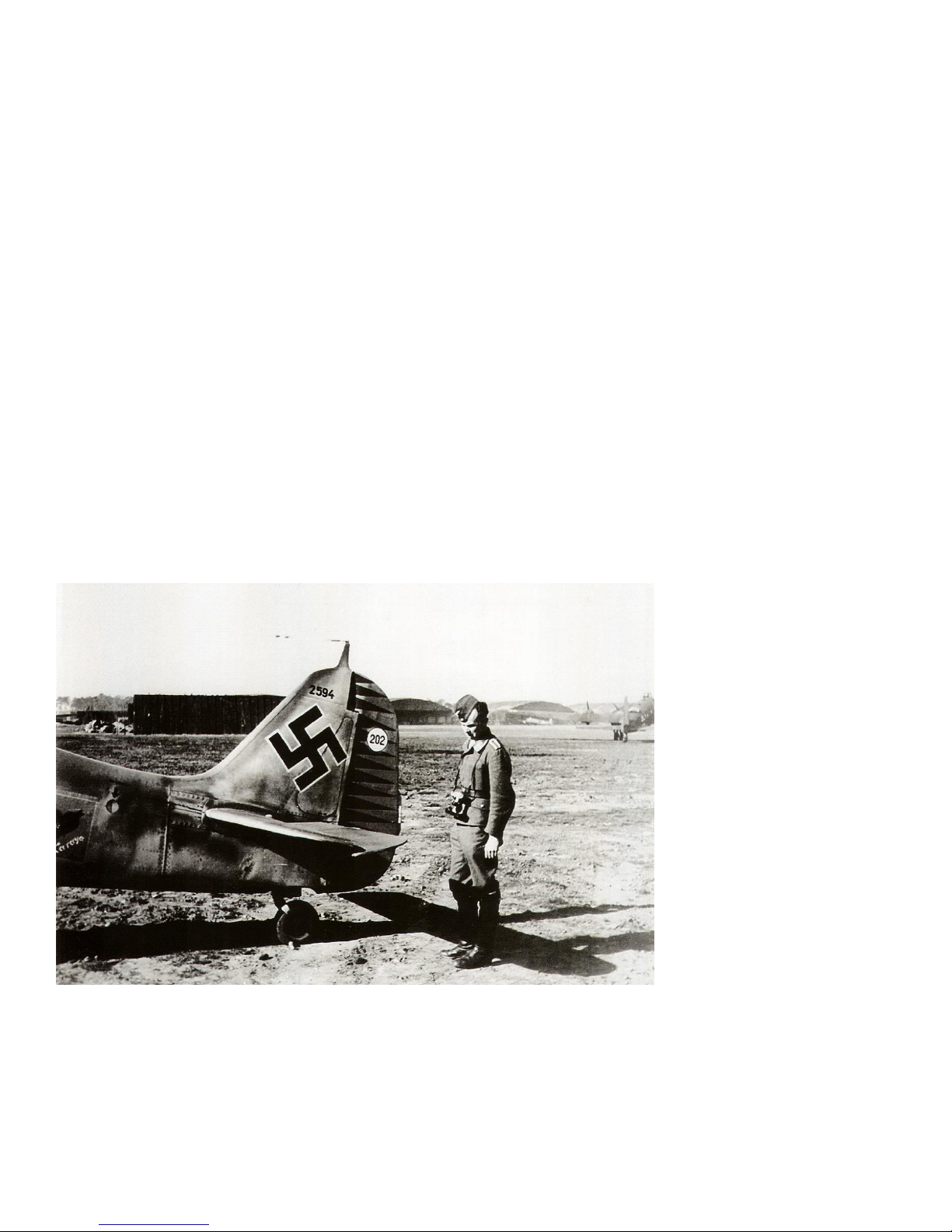
“Red Tulip” – Hermann Graf
When you’re one of the best fighter aces of all time, why not brightly paint your cowling and rudder to something that
can’t be missed? This scheme is depicting the fighter flown by Hermann Graf. Serving on both the eastern and western
front, Graf was the first ace to shoot down more than 200 adversaries; 212 victories and 830 combat missions.
Seen in this photo with 202
victories, Graf was awarded the
highest military decoration at
the time, the Knights Cross of
the Iron Cross with Oak Leaves,
Swords and Diamonds.
An instructor of other aces, an
emblem of his fighter group can
be seen on the right hand side
of the plane; eagle teaching
younger eagles. The emblem on
the left hand side made up of
previous flight groups, the
Karaya-Staffel emblem. The rest
of the markings feature on
many of Hermann’s aircraft.
Research was challenging as Hermann flew more than one FW190, as well as a number of Bf109’s. His technique was
based around getting very close to his prey before firing. He got so close that he was often firing through debris. So
while he was not shot down, he went through a number of aircraft. The recreation of the details on this scheme were
from singling out this exact airplane, and recreating it as closely as possible including the actual reproduction of the
seemingly random camouflage pattern.

3
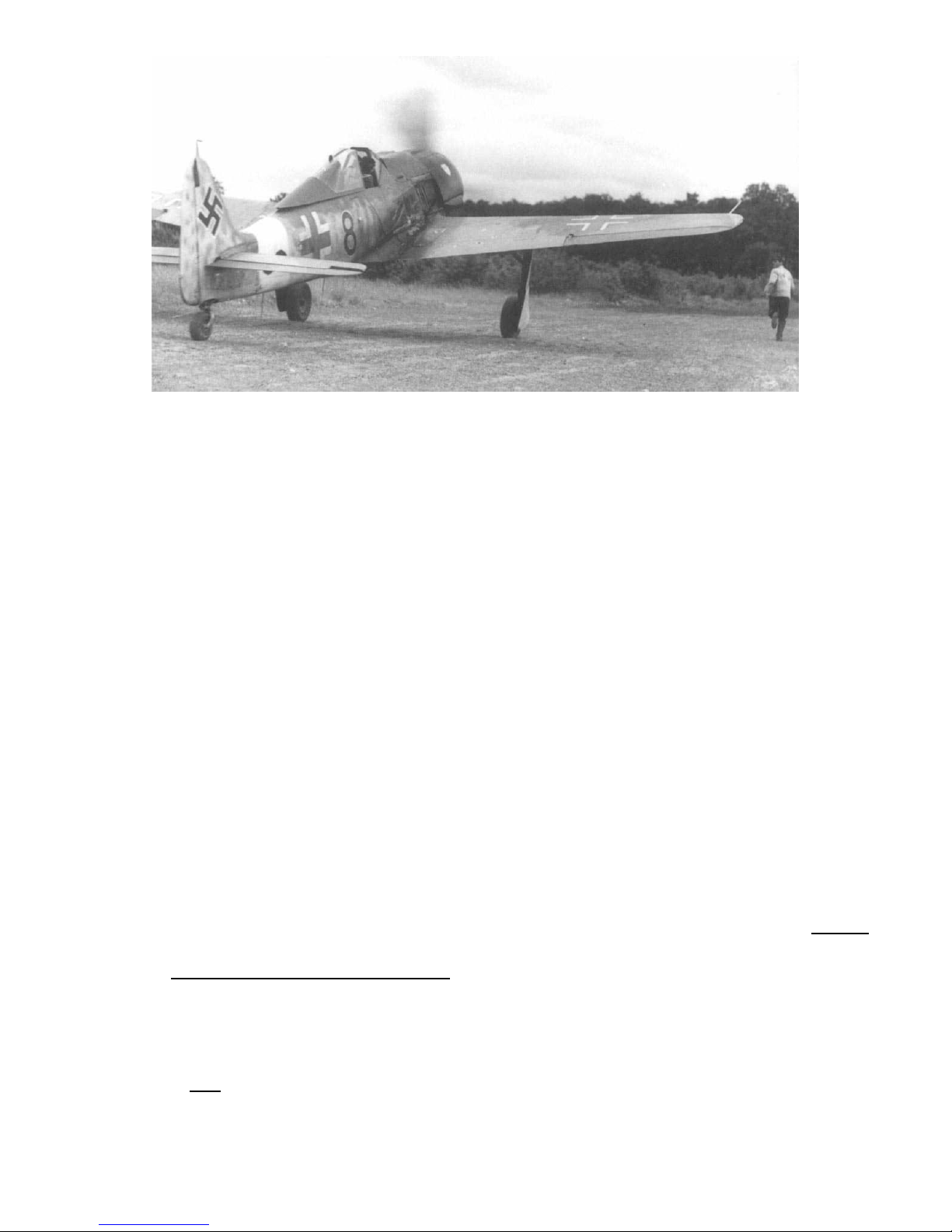
“Black Eight” - Willi Maximowitz
Willi was more into bombers. Credited with 27 victories, 15 of them were four engine bombers. At least one of these
bombers (though he claimed a second also) was taken by, get this, ramming it. April 20 1945, Willi failed to return from a
combat mission. If you use the airplane itself as a blunt instrument, going out with your boots on was probably a
foregone conclusion. Maximowitz was posthumously awarded the gold German Cross.
4
THIS IS NOT A TOY!
Serious injury, destruction of property, or even death may result from the misuse of this product. Extreme Flight RC is
providing you, the consumer, with a very high quality model aircraft component kit, from which you, the consumer, will
assemble a flying model. It is beyond our control to monitor the finished aircraft you produce. Extreme Flight RC will in
no way accept or assume responsibility or liability for damages resulting from the use of this user assembled product.
This aircraft should be flown in accordance with the AMA safety code. It is highly recommended that you join the
Academy of Model Aeronautics in order to be properly insured and operate your model at AMA sanctioned flying fields
only. If you are not willing to accept ALL liability for the use of this product, please return it to the place of purchase
immediately.
Extreme Flight RC, Ltd. guarantees this kit to be free of defects in materials and workmanship for a period of 30 DAYS
from the date of purchase. All warranty claims must be accompanied by the original dated receipt. This warranty is
extended to the original purchaser of the aircraft kit only. Extreme Flight RC in no way warranties its aircraft against
flutter. We have put these aircraft through the most grueling flight tests imaginable and have not experienced any
control surface flutter. Proper servo selection and linkage set-up is absolutely essential. Inadequate servos or improper
linkage set up may result in flutter and possibly the complete destruction of your aircraft. If you are not experienced in
this type of linkage setup or have questions regarding servo choices, please contact us at info@extremeflightrc.com or
770-887-1794. It is your responsibility to ensure the airworthiness of the model.

Tips for Success
Before starting assembly, take a few minutes to read the entire instruction manual to familiarize yourself with
the assembly process.
Use a fresh bottle of thin CA with a fine glue tip when attaching the CA hinges. This will ensure that the proper
amount of CA wicks into the hinge and surrounding balsa wood and creates a proper bond between the wood
and hinges.
Apply a couple drops of CA to high stress areas such as anti-rotation pins, landing gear mounts, servo trays and
motor box joints.
Take the time to properly balance and trim your aircraft and set up rates and exponential values. Your flying
experience will be greatly enhanced by doing this.
Note that this aircraft is printed using our printed covering technique. Your aircraft has been sealed with a matte
clearcoat. Due to climate changes, wrinkles may develop in the covering. These are easily removed with a little
bit of heat. Use your heat gun or a covering iron with a soft cotton iron sock, medium heat, and a gentle
technique. Just like regular covering, you can remove any wrinkles that develop over the life of your aircraft, but
go a little slower and be a bit more careful for best results. Your iron will feel a bit different gliding over this
sealed covering than regular. Be careful not to use too much heat as the covering may shrink too much and
begin to lift at the edges. Take your time, and the beautiful finish can be easily maintained.
Items Needed For Build
1. Masking tape
2. Thin and medium CA adhesive. We highly recommend Mercury M5T thin and M100XF
3. 30 minute epoxy
4. Blue Locktite thread locker
5. Small and medium Philips head screwdriver
6. Metric hex drivers
7. Needle nose pliers
8. Denatured Alcohol (methylated spirits) for epoxy clean up with paper towels
9. Plastic compatible adhesive/contact adhesive (shoe goo, seal-all work fine)
Required Equipment
1. Torque 4016T-500 brushless motor
2. Airboss Elite 80-Amp ESC
3. External BEC to power radio system
4. QTY 6 mini (~30g) servos (metal gears recommended)
5. 6S 3300 – 4400mah LiPo flight battery
6. 8 channel computer radio
7. 2x 12” servo extensions (ailerons)
8. 2x 6” servo extensions (flaps)
9. Recommended: one three-servo surface mount plug and one two-servo
surface mount plug sets for easy wing equipment connection.
10. Prop and spinner (scale three blade spinner for the FW190 available from
ExtremeFlight)
11. 2x 1” servo arms (ailerons)
12. 2x 3/4" – 1” servo arms (flaps)
13. 2x 3/4" arms (elevator and rudder)
5
6
LET’S BEGIN !!!
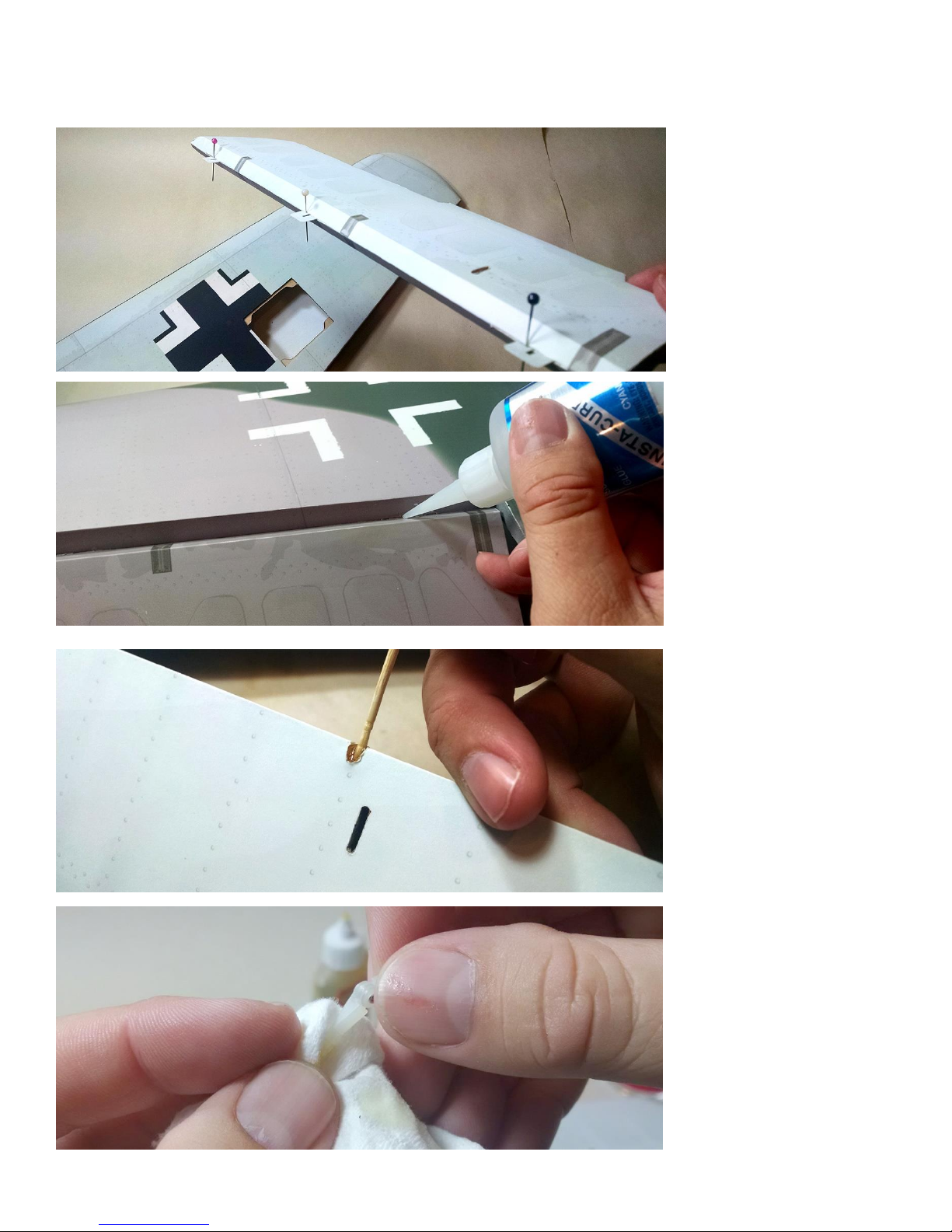
Hinging the aileron. Remove
the aileron, and place some
pins into the center of the
hinges. This will prevent the
hinges from pushing into only
one side of the control surface
of the wing.
Insert the aileron into the wing,
and remove the pins. Make
sure that the aileron is aligned
so that the end of it is in line
with the wing tip. Then holding
it deflected, add a couple of
drops of thin CA to each hinge.
Allow to cure, then flip the wing
over and apply a drop to each
hinge on the opposite side.
Remove the flap from the wing,
and remove the hinges. Mix
some epoxy and use a tool (like
a toothpick) to coat the inside
of the hinge holes with epoxy.
Note: We recommend doing
one side of the hinge at a time.
Gluing the hinges into the flap
and allowing to cure before
gluing into the wing.
Wipe some epoxy onto the
barbed end of the hinge.
Note: One end of the hinges on
the flaps have been shortened.
The shorter end is to go into the
flap surface itself, and the long
end into the wing.

7
Insert hinge into the flap. Wipe
with denatured alcohol
(methylated spirits) to clean
away any excess glue and
ensure the hinge moves freely.
With all hinges glued into the
flap surface, repeat the hinge
gluing steps for the other side
and insert the flap into the
wing.
Note: Before the glue is fully
cured, test that the flap moves
freely. If needed, wipe a drop of
denatured alcohol onto each
hinge to free it up.
Next are the control surface
horns found in the “Main Wing”
bag.
Using some coarse sandpaper
(100-150 grit is ideal), rough up
the surface of the tabs on the
control horns (the part of the
horn that inserts into the wing).
This will provide better
adhesion for the glue.
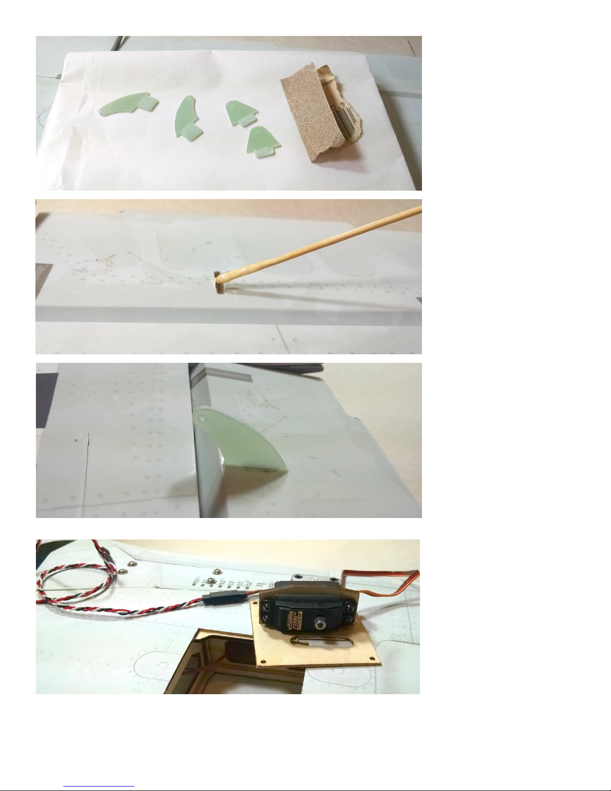
8
Note: The curved horns are for
the ailerons, and the triangle
shaped horns are for the flaps.
Mix up some epoxy, and use a
tool/stick to pace into the holes
of the control surface.
Wipe some epoxy onto the
sanded tab area of the horn,
and insert into control surface.
Clean any excess glue with
denatured alcohol (methylated
spirits).
Repeat for all flap and aileron
horns.
Using the hardware that came
with your servo, mount the
servos to the removable servo
access doors as shown.
Note: We recommend screwing
the servo to the mount and
then removing it to apply a drop
of thin CA to the servo screw
holes to make them stronger.
 Loading...