

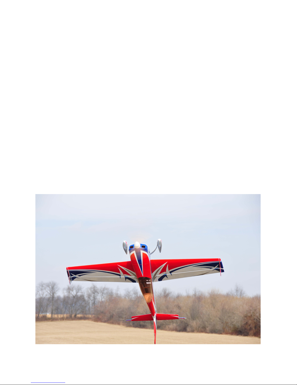
Extreme Flight Extra 330 LT Assembly Manual

Assembly Manual / Airframe – 75” Extra 330 LT
Thank you for purchasing this 3DHobbyShop by Extreme Flight ARF RC aircraft. If you have
any issues, questions, concerns or problems during assembly, please contact our tech
department at: Info@extremeflightrc.com or 770-887-1794 10am-5pm Eastern Monday thru
Friday.
SAFETY in Assembly
During assembly of this aircraft, you will be asked to use sharp knives and hobby adhesives.
Please follow all safety procedures recommended by the manufacturers of the products you use,
and always follow these important guidelines:
ALWAYS protect your eyes when working with adhesives, knives, or tools, especially power
tools. Safety glasses are the best way to protect your eyes.
ALWAYS protect your body, especially your hands and fingers when using adhesives, knives,
or tools, especially power tools. Do not cut toward exposed skin with hobby knives. Do not
place hobby knives on tables or benches where they can roll off or be knocked off.
ALWAYS have a first-aid kit handy when working with adhesives, knives, or tools, especially
power tools. ALWAYS keep hobby equipment and supplies out of the reach of children.
SAFETY in Flying
This is NOT a toy! It is a very high-performance RC airplane capable of high speeds and
extreme maneuvers. It should only be operated by a competent pilot in a safe area with proper
supervision.
ONLY fly your aircraft in a safe, open area, away from spectators and vehicles and where it is
legal to fly. NEVER fly over an unsafe area, such as a road or street.
NEVER fly near overhead power or utility lines. If your airplane ever becomes stuck in
a line or a tree DO NOT attempt to retrieve it yourself. Contact the authorities for
assistance in retrieving your aircraft. Power lines are DANGEROUS and falls from
ladders and trees CAN KILL!
Never fly too close to yourself or spectators.
Spinning propellers are DANGEROUS!
Never run your motor inside a house or building with the propeller attached Remove the
prop for safety. Always fly within your control.
Always follow manufacturers instructions for your radio system.
Always preform a pre-flight check of your aircraft to be certain of the aircraft's
airworthiness.
Always obtain proper insurance before flying. Always fly model aircraft in accordance
with the Academy of Model Aeronautics (AMA) Safety Code. Visit the AMA's website
at www.modelaircraft.org for more information.

Limits of Responsibility
Extreme Flight provides high-quality aircraft and components to it's
customers and end users. These aircraft and components are assembled
by the end user to produce a flying model. It is beyond Extreme Flight's
control to monitor the end user's completed aircraft. Therefore, Extreme
Flight in no way accepts or assumes responsibility or liability for damages
resulting from the end user assembled product. The end user assumes all
responsibility and liability in use of Extreme Flight aircraft and components
and agreeing to hold harmless Extreme Flight, it's distributors and dealers.
Required Items
Hobby Knife
Small Phillips Screwdriver
Set Metric Allen Wrenches
Scissors
Small Pliers
Wire Cutters
Adjustable wrench
Masking tape
Drill and drill bits
Threadlocker (Blue Loctite)
Optional:
Heat gun and covering iron
Dremel tool
Assembly Instructions – Read completely before starting assembly!
UNPACK :
Unpack your airplane and examine the components. Check for damage of any kind. If you have
damage, please contact Extreme Flight to discuss. Contact info listed above.
WRINKLES :
Your airplane was packed in plastic at the factory without any wrinkles in the covering. You may
notice some wrinkles now; more likely, you will notice a few in a day or two or the first time you take
the plane out to the flying field. These wrinkles are the result of wood shrinkage and/or expansion.
Balsa wood changes size and shape slightly as it is exposed to varying humidity in the air. This is a
natural property of balsa wood. As your airplane adjusts to the weather in your part of the world,
wrinkles may appear and disappear. Wrinkles may be removed with the gentle application of heat to
the covering material on your airplane. The best tools to use are a heat gun and covering iron. Apply
the heat gently: the covering material will shrink as you apply the heat, and this will remove the
wrinkles. BE CAREFUL! Too much heat applied too quickly can damage the covering, either by
causing it to pull away from the wood at seams and corners or even by melting it. The covering will
shrink at low temperature with patient application of heat. Wrinkles in the covering DO NOT affect
flight performance. If you must shrink on a color-seam, use the iron and go slowly and carefully to
avoid any pulling or lifting at the seam.
Remove the canopy before attempting to use heat on your covering! The canopy is made of thermoactivated plastic and WILL deform with the application of heat. Do not apply heat to the canopy.
PAINT:
If you need to clean your airplane, we recommend using a damp towel. The paint used on the canopy
and cowl is not safe for all cleaners. In particular, DO NOT use alcohol on these parts, it will remove
the paint.
Let’s get started!

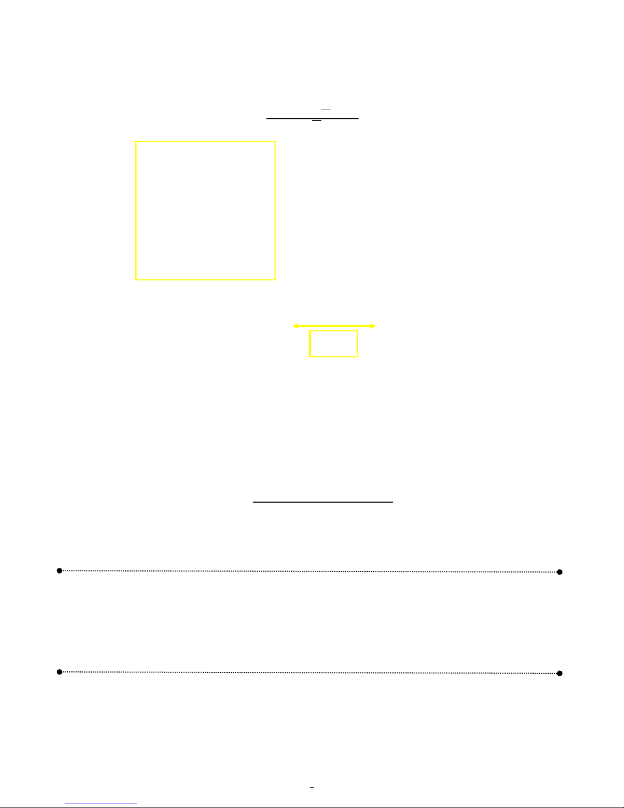
Install the wheels onto the axles and secure with the wheel collars, as shown.
(1.5mm Metric Allen Wrench/Driver)
Slide one wheel/axle assembly into a wheel pant as shown above. Be sure to orient the wheel pants to face
forward when landing gear is installed on the fuselage.
Tighten the locknut as shown to secure the assembly onto the gear leg. Repeat for other side.
(10mm Ny-Lock Nut)
4
* Note: graphics in manual may differ from your airframe*

Install wood screws through gear into pants as shown.
(Tip: Drilling a 1/16” pilot hole will ease screw installation)
Attach the gear to the fuselage with 4mm screws, use loctite.
(3mm Metric Allen Wrench/Driver)
Install gear cover plate as shown, using thick CA, epoxy glue or clear silicone.
5
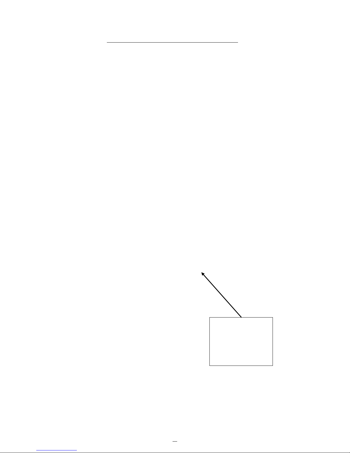
Install tailwheel onto fuselage as shown, using QTY 2 screws and washers, with loctite.
Note: Rear blind nut hole is located 2.3” from aft vertical stabilizer.
(3/32 Allen Wrench/Driver)
\
The 75” Extra 330 LT comes with pre-hinged and pre-gap-sealed wings/ailerons to save time during your
build. The airplane also comes with the hinges pre-glued to the rudder and elevator halves to further lessen
the work. All tail hinges are the same type and work the same way. The below instructions cover the use of
polyurethane and epoxy glue. If you are using a type of specific RC-hinge glue, follow the direction on the
hinge glue bottle.
Quick HOW TO use PU (Polyurethane) glue: (Using hinge installation as the example)
1) Apply Petroleum Jelly to center hinge joint using cotton swab.
2) Lightly dampen all holes with water. (More important in dry climates)
3) Squeeze in a small amount PU glue into all hinge holes.
4) Install hinges.
5) Wipe away glue as it expands and foams using rubbing or denatured alcohol. (Keep an eye on it and
wipe as required for the first 10-20 mins)
6) Allow to fully cure.
2.3”
Builders Tip:
Remove tail wheel assembly
set screws one at a time and
re-torque with loctite. This
will assist in providing a long
service life from your tail
wheel assembly.
1.5mm Metric Al
len
Wrench/Driver
Tail W
heel
Rudder Hinging
6

1) Apply Petroleum Jelly to center hinge joint using cotton swab.
2) Lightly dampen all holes with water. (More important in dry climates)
7

3) Squeeze in a small amount PU glue into all hinge holes.
4) Install rudder. BE SURE to position tail-wheel tiller wire as shown.
5) Wipe away glue as it expands and foams using rubbing or denatured alcohol. (Keep an eye on it and wipe
as required for the first 10-20 mins)
8

Remove covering fr
om areas indicated above.
Recommended covering removal tools:
1) Hobby Knife
2) Soldering Iron (Pencil Tip)
3) Hot Knife
Covering
Removal
9
Remove covering over the horizontal stabilizer opening. Insert horizontal stabilizer – DO NOT GLUE YET.
Temporarily install the wings onto the fuselage.
Use a ruler to center and align the stab side-to-side.
Horizontal Stabilizer Installation
Builders Tip:
Use foam material
to hold the
horizontal stabilizer
in place while
aligning.
10
 Loading...