

Page 1
Page 2
Please read the following paragraph before beginning assembly of your aircraft!
THIS IS NOT A TOY! Serious injury, destruction of property, or even death may result from the misuse of this product. Extreme
Flight RC is providing you, the consumer with a very high quality model aircraft component kit, from which you, the consumer,
will assemble a flying model. It is beyond our control to monitor the finished aircraft you produce. Extreme Flight RC will in no
way accept or assume responsibility or liability for damages resulting from the use of this user assembled product. This aircraft
should be flown in accordance to the AMA safety code. It is highly recommended that you join the Academy of Model Aeronautics in order to be properly insured, and to operate your model at AMA sanctioned flying fields only. If you are not willing to
accept ALL liability for the use of this product, please return it to the place of purchase immediately.
Extreme Flight RC, Ltd. guarantees this kit to be free of defects in materials and workmanship for a period of 30 DAYS from the
date of purchase. All warranty claims must be accompanied by the original dated receipt. This warranty is extended to the original purchaser of the aircraft kit only.
Extreme Flight RC in no way warranties its aircraft against flutter. We have put these aircraft through the most grueling flight
tests imaginable and have not experienced any control surface flutter. Proper servo selection and linkage set-up is absolutely essential. Inadequate servos or improper linkage set up may result in flutter and possibly the complete destruction of your aircraft.
If you are not experienced in this type of linkage set-up or have questions regarding servo choices, please contact us at info@
extremeflightrc.com or 770-887-1794. It is your responsibility to ensure the airworthiness of your model.
Congratulations on the purchase of a high-performance model aircraft from Extreme Flight. This basic build manual will guide
you through the assembly process. All aircraft from Extreme Flight assemble in fundamentally the same way, so we have created
this manual to cover the 85-93” class of aircraft which are powered by 50-76CC gas engines or 6KW 12S electric.
Please read over the manual completely before beginning. This will give you an overall understand of the assembly process and
familiarize you with the tools and supplies you will need.
Extreme Flight consantly upgrades and improves its products. Hardware and details may change, but the basic process remains
the same. If you are confused about a step, please call or email us at the contact information on our website, we will be glad to
help.
Your aircraft has been on a journey around the world since it left our factory. Although the covering material was perfectly
smooth when it was boxed up, changes in weather and humidity may have wrinkled the covering material. For certain, wrinkles
will appear in the covering once you have unpacked your aircraft and it adjusts to the atmospoheric conditions in your region.
Learning to remove wrinkles from covering is a necessary skill to maintain your wood aircraft.
Your Extreme-Flight produced aircraft is covered in Ultracote covering material (US market name), also called Oracover in global
markets. If you need replacement covering to repair damage, Ultracote/Oracover is widely available from retail hobby suppliers.
Also, each roll of Ultracote/Oracover includes excellent instructions which are also available online. Please refer to them for
details about working with and/or repairing your covering.
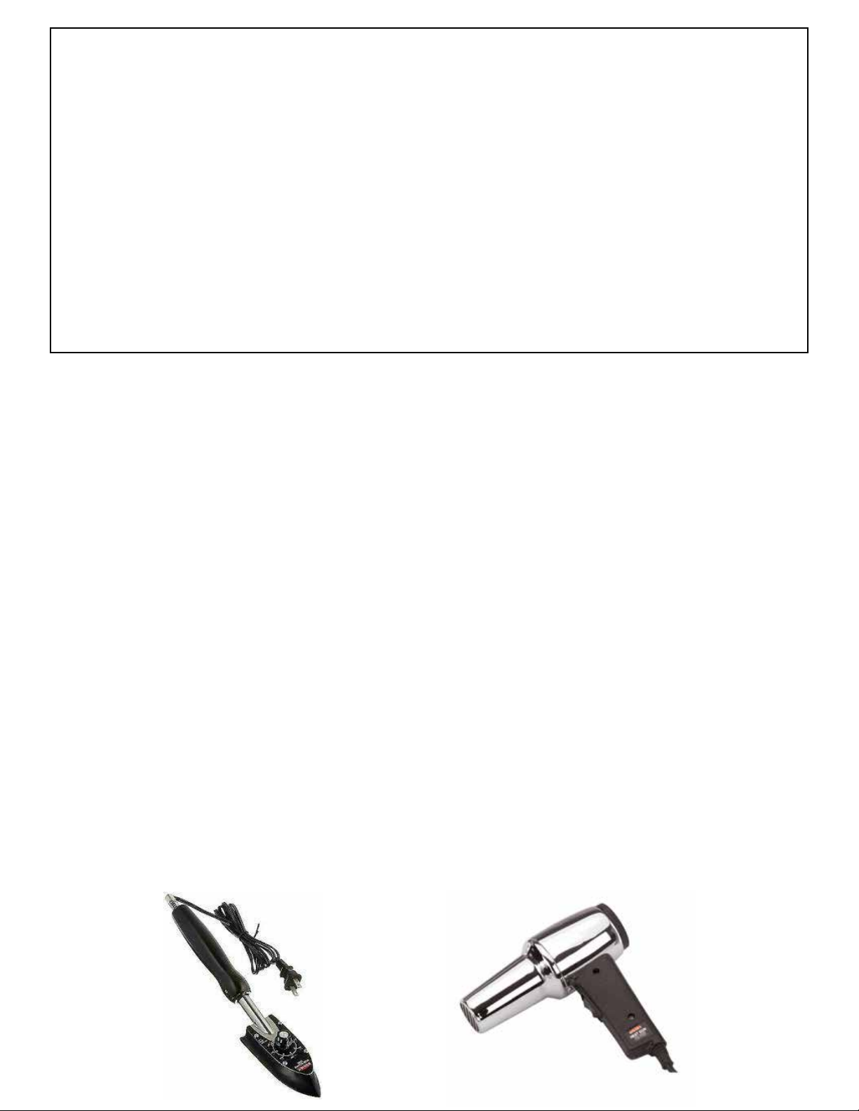
The basic tools are a covering iron and a hobby heat gun. Start by using the iron at 220F (104C) to seal all of the edges on the
covering scheme. This is CRITICAL on the leading edges of wings and stabilizers. Then use the iron at 300F (149C) or a heat
gun to shrink out any wrinkles in the covering. Remove the plastic canopy from the aircraft when using a heat gun to protect it
from heat damage. GO SLOWLY AND CAREFULLY to avoid over-shrinking or burning the covering. This is a skill which takes a
bit of practice. There are many tutorial videos online demonstrating shrinking wrinkles from Ultracote.
Page 3
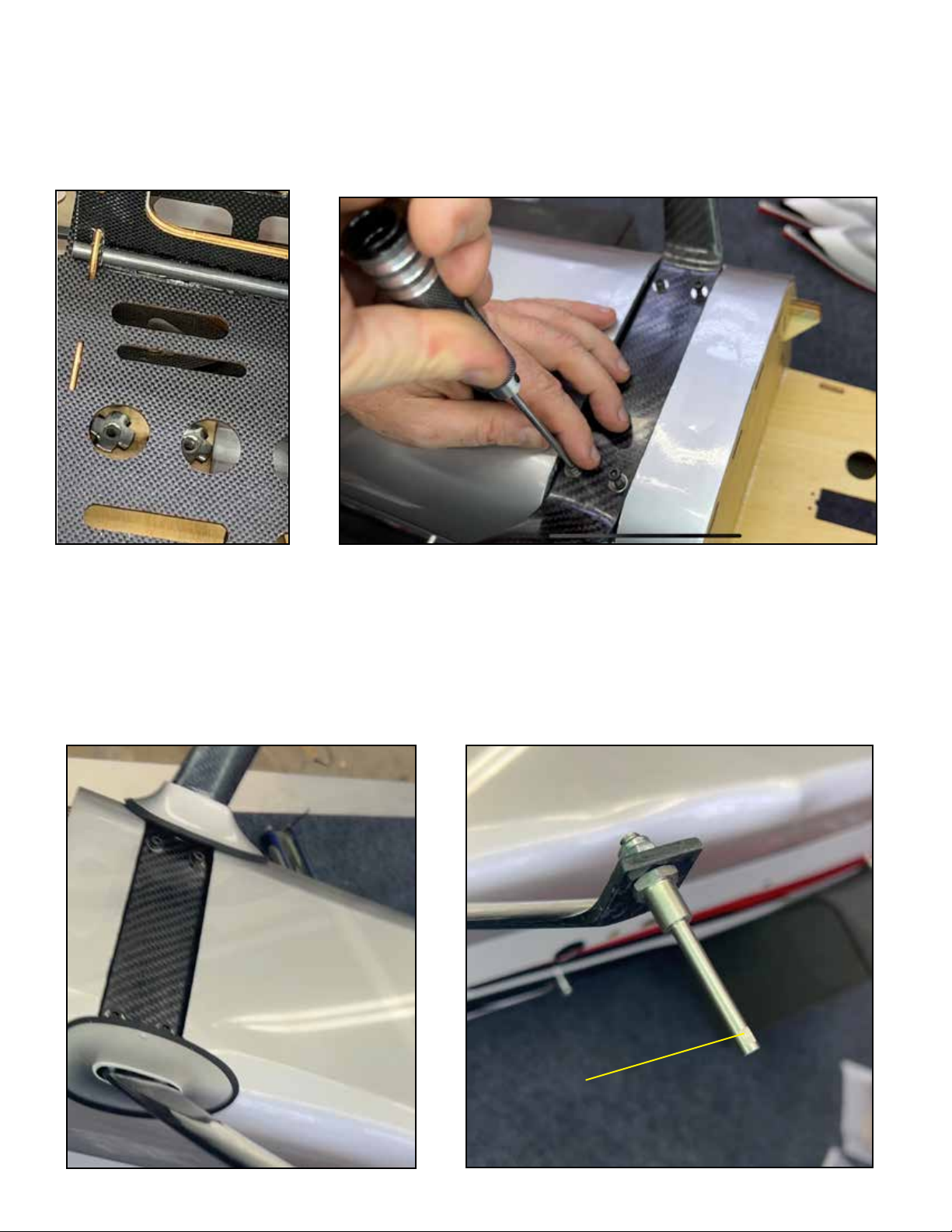
Extreme Flight aircraft use a carbon-fiber high strength landing gear. Depending on the model, it may sweep forward (Extras,
Slicks, Yaks, MXS, Edge) or back (Gamebird) when installed. Consult photos of your aircraft if you are unsure which direction to
install the landing gear.
The landing gear installs onto the fuselage using four screws and washers, which thread into either locking nuts, or pre-installed
blind nuts in the fuselage. Use blue loctite here. Your kit may include landing gear fairings made of either fiberglass or wood. The
fairings may need to be fit to the landing gear legs, use a folded piece of sandpaper if you need to open the fairings. Test fit these
fairings to find the best fit, then attach to the landing gear legs with a dollop of GOOP rubberized adhesive. Use some masking
tape to hold the fairings in position if necessary. Allow to cure. Locate the wheel axles and attach to the landing gear legs as
shows using the locking nuts. Find the flat spot on the end of the axle, make sure it points DOWN when the aircraft is upright.
Flat Spot
Page 4
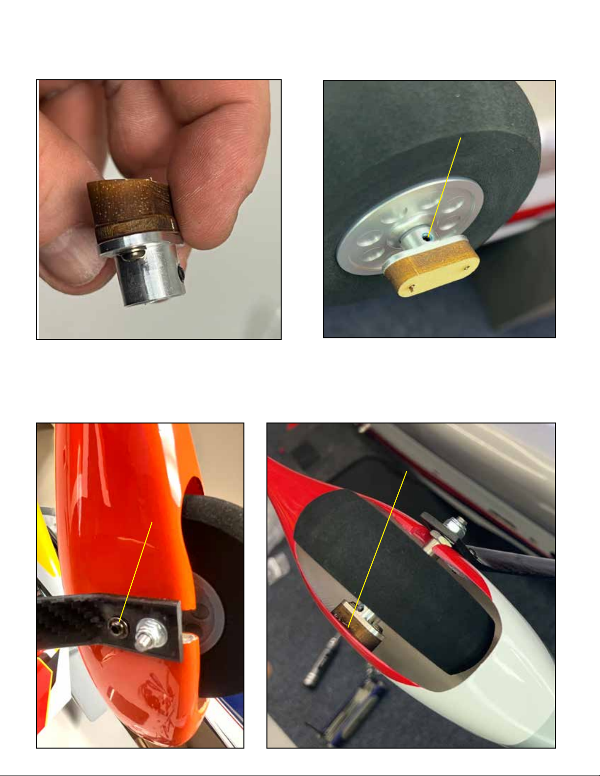
Most Extreme Flight aircract use full-coverage wheel pants (The 85” Yak is one exception) and so they have a wheel pant
support integrated into the outer wheel retainer. Assemble the retainer from the wood piece and aluminum piece with screws as
shown. Place the wheel on the axle and retain with this assembly. Use blue Loctite on the set screw.
Loctite here
Install the wheel pant over the wheel and axle, tighten to the landing gear with one or two screws as designed, using blue loctite.
The wheel pant support should sit against the pant as shown. Flex the pant away from the retainer and apply some epoxy glue
between the retainer and pant. By stabilizing the pant, this design lengthens the life of your wheels pants. Just like on full-size
aerobatic aircraft, however, wheel pants take a lot of abuse and over its life your aircraft will probably need a replacement set.
epoxy glue here
Loctite here
Page 5
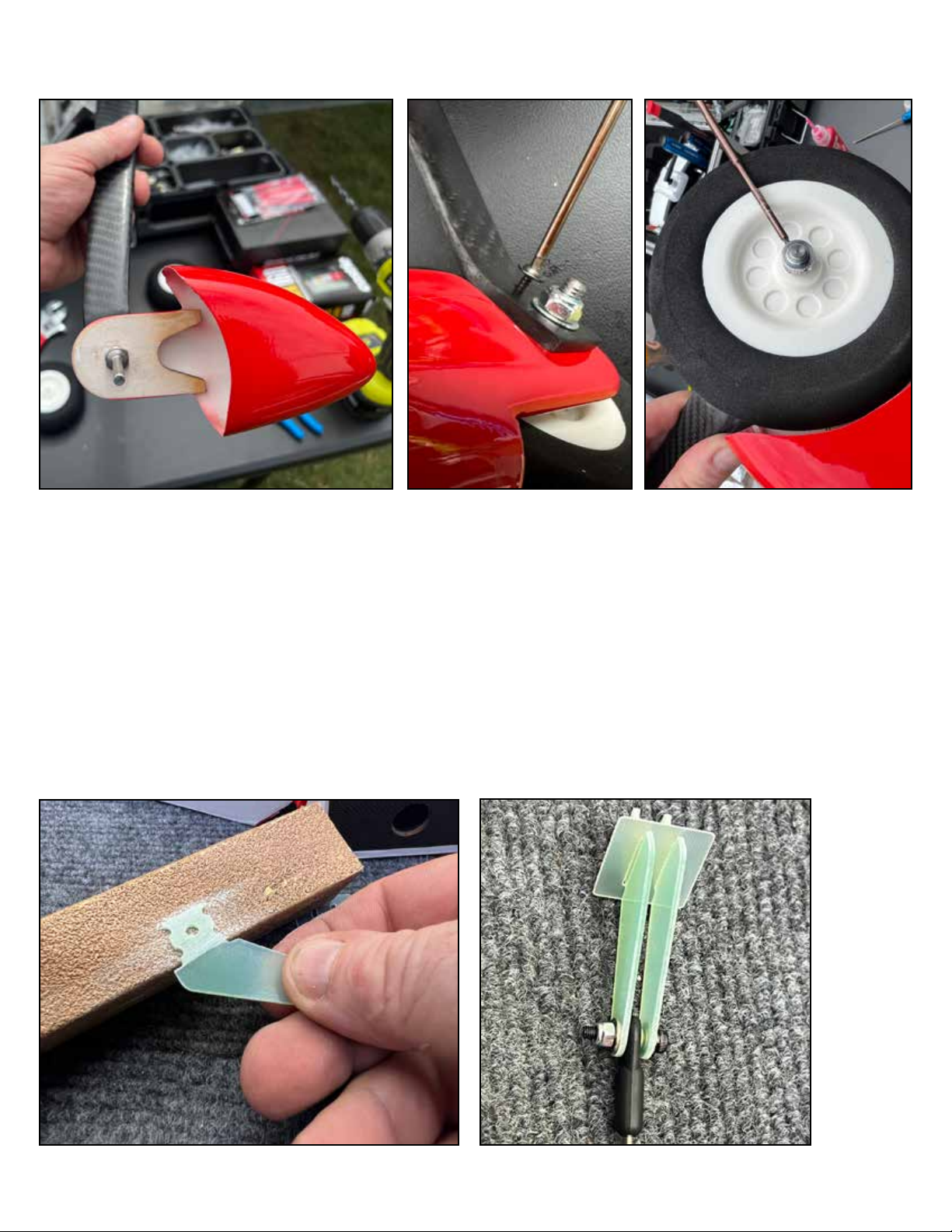
The 85” Yak uses a half-pant on its wheel. To install these, drill holes as appropriate for the wheel axles, and sandwich the halfpant between the axle and landing gear as shown. Lock the half-pant in place with included wood screws as shown. Finish with
a wheel collar to retain the wheel, use blue loctite on the set screw.
A note about control surfaces:
All Extreme Flight aircraft in this size class are currently being shipped with pre-hinged ailerons and elevators, and gap seals
already fitted to these surfaces.
All of the control horns on your aircraft install in the same way. The horns insert into slots in the control surface, where epoxy
glue forms a strong shear joint. They also have trim plates which go on top and help to hold correct geometry during installation.
Begin by scung the area of the control horn which will be inserted into the control surface with sandpaper (any grit 120-280
is fine) as shown. This cleans the horn and provides a rough sirface for the epoxy glue to grab on to. Then, assemble the horns
with the trim plates and correct pushrod assembly as shown, using washers and locking nuts.
Page 6
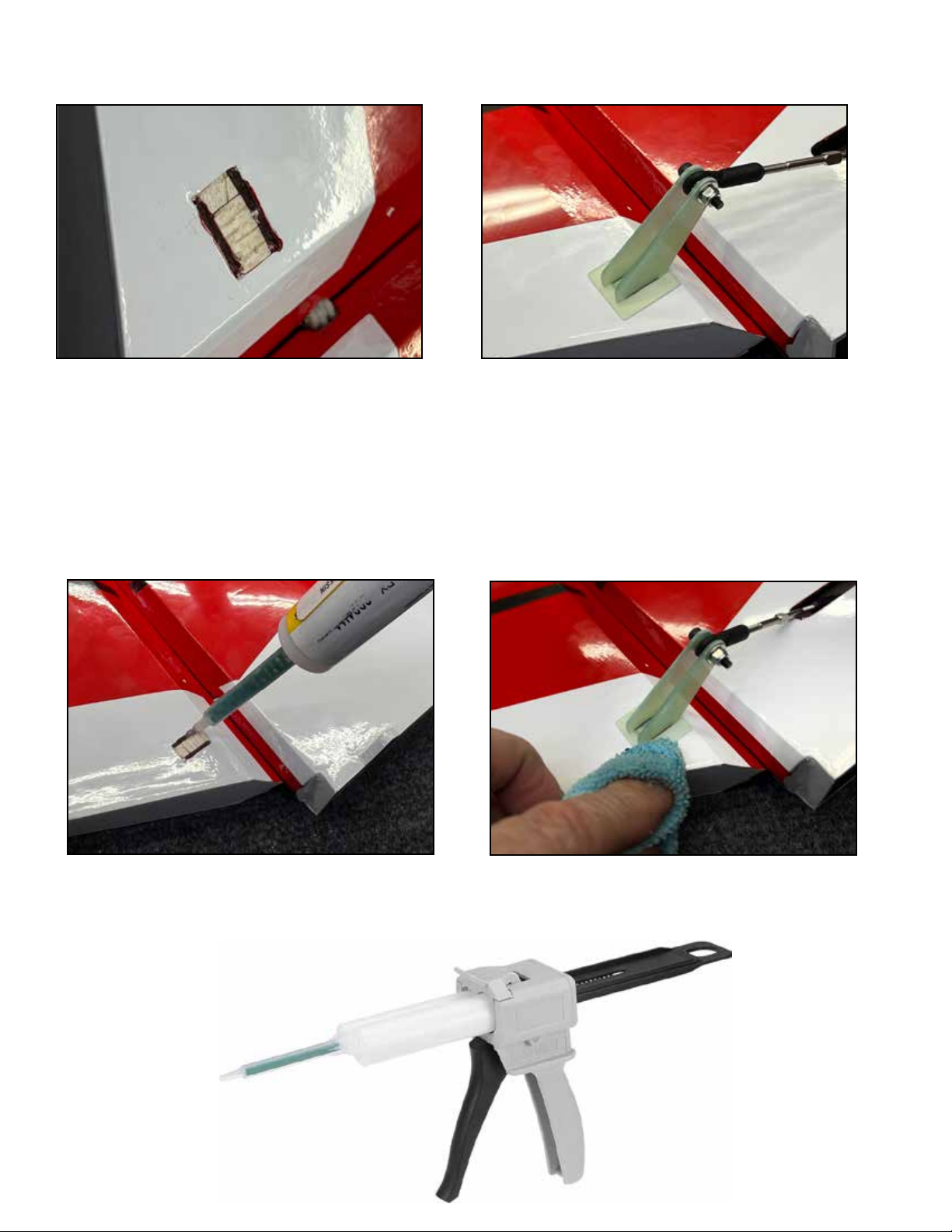
Locate the slots in the control surface, remove covering as shown with a hobby knife. Test fit the horn into the surface, make
sure it seats fully. If necessary, remove any sawdust or debris from the slot with a hobby knife
Apply good quality 15 or 30 minute epoxy into the slots and to the scued area of the horn. Using excess epoxy is a good idea
here, as we want complete coverage and can easily clean up any excess which squeezes out.
Press the horn firmly into the slot and make sure it seats all the way. Clean up any excess epoxy with a rag and denatured alcohol. Allow to cure.
NOTE: The design of the slot and horn will place the screw approximately over the center of the hinge line. It is not necessary
that the screw be precisely over the center, during radio setup we will correct for any slight error using the endpoints function.
We use an epoxy gun to apply expoy precisely into the horn slots. While the epoxy gun is a great tool, it is not necessary. If you
hand mix your epoxy, be sure to get plenty of glue down into the slots.
Page 7
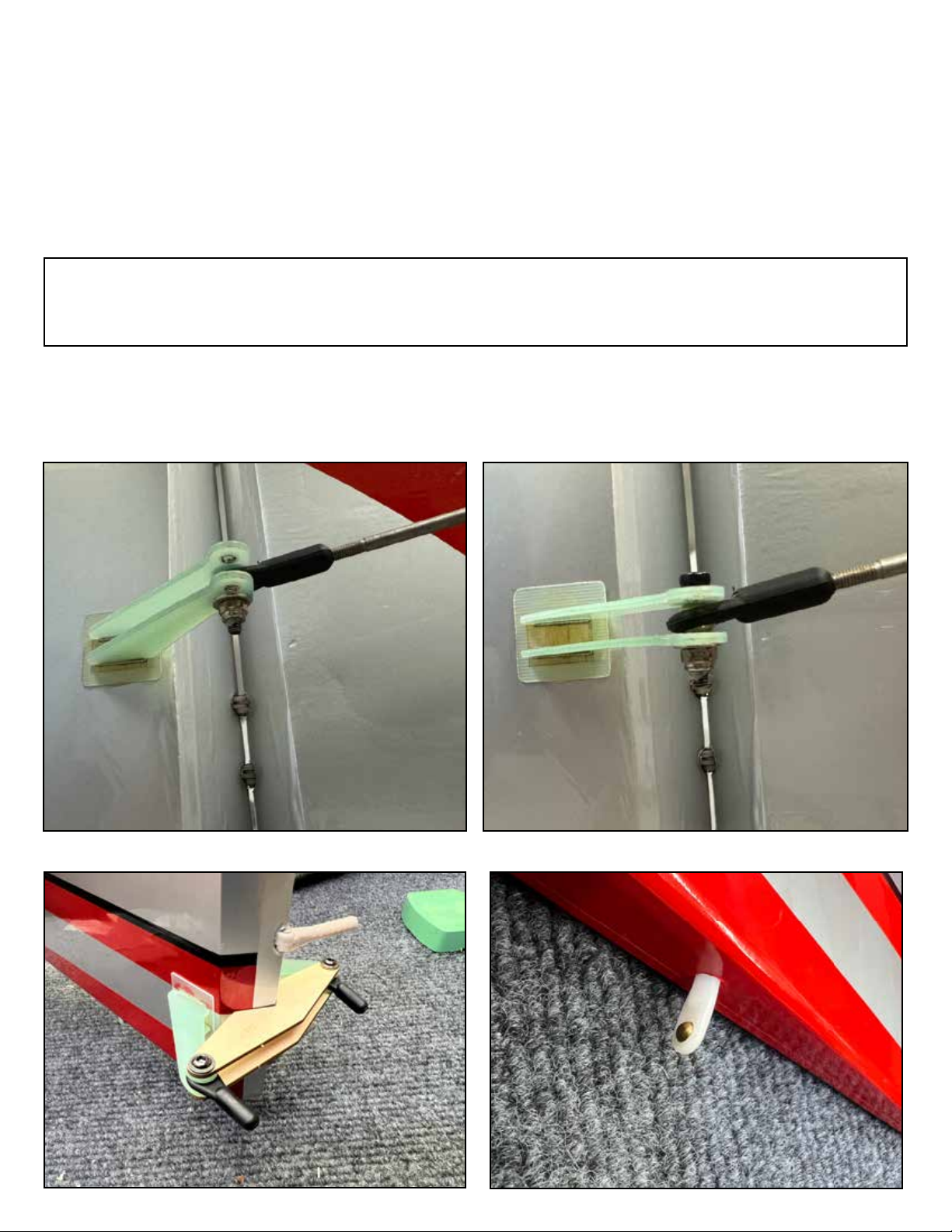
Our latest version Extreme Flight giant scale aircraft arrive with the wings and stabilizers pre-hinged and gap sealed. The only
hinges you need to attach are the fuselage-side of the rudder hinges. Before you install the rudder to the fuselage, if you definitely want to use pull-pull cable actuated rudder with the rudder servo at the front, use the included jig as shown to install the rudder control horns first. We recommend the pull-pull style of rudder on the 85” Gamebird with all power systems, and for the 85”
Muscle Bipe with twin cylinder gas or electric. For other aircraft we recommend pull-pull if using a DA-50 or another lightweight
engine.
If using a rear-mounted rudder servo, locate the servo mounting location in the fuselage and make sure the servo and horn are
on the same side of the airplane. Install the horn as you did for the aileron and elevator.
If using pull-pull rudder controls, you will install two rudder horns, one on each side of the rudder. A wooden jig is included in the
kit to help align these horns during installation as shown. It replaces using a ruler to center the horns side-to-side. NOTE: this installation does not need high-precision. Use the jig as needed to keep the horns within 1-2mm of each other, but we will correct
for any errors during the servo setup process.
Also install the rudder tiller keeper (we use a small nylon ball link for this purpose) in the bottom of the rudder as shown with
epoxy glue.
Page 8
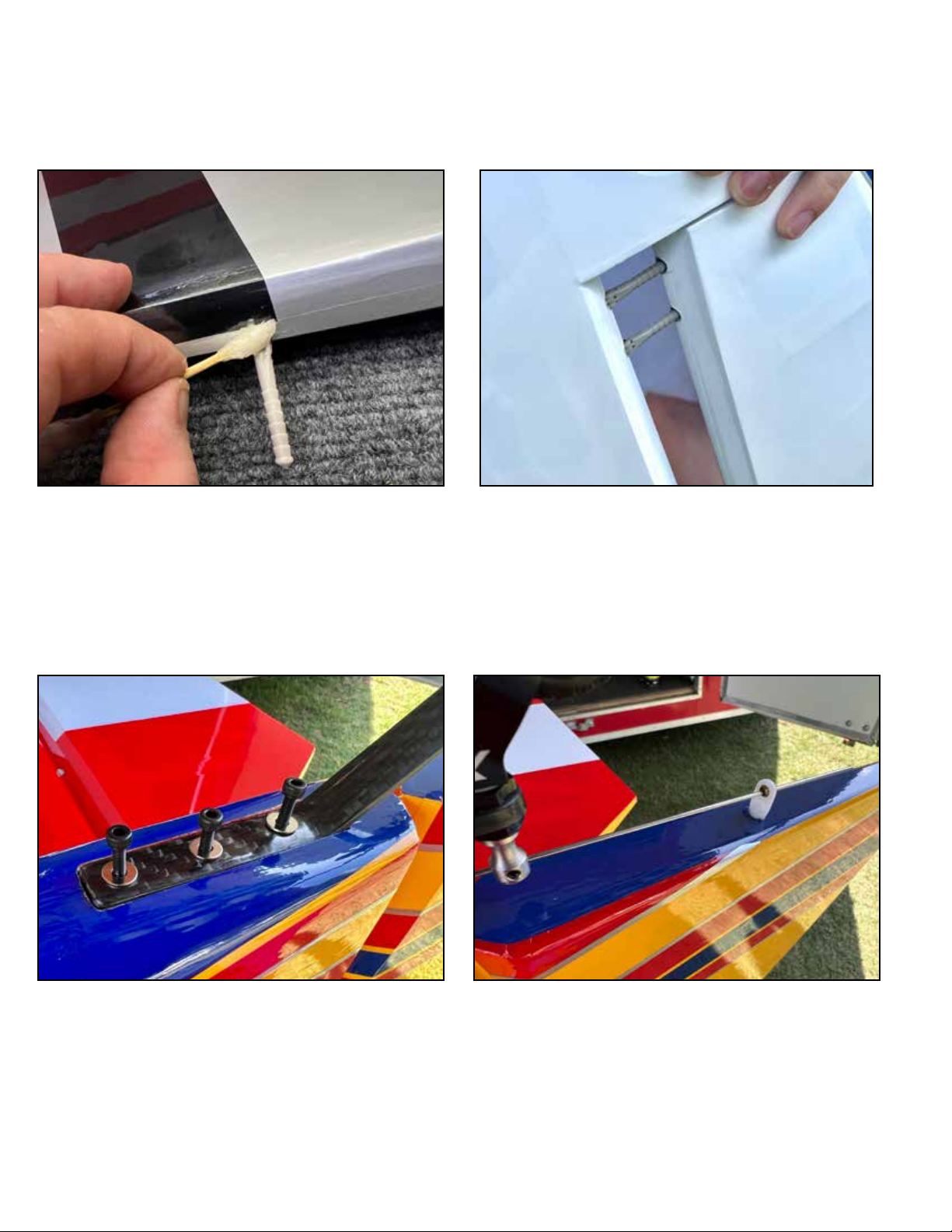
Apply a bit of petroleum jelly (vaseline) to the center of the rudder hinge points to protect the hinge mechanism from glue, and
glue the hinges into the fuselage using 15 or 30 minute epoxty. Clean up any excess epoxy with denaturted alcohol. Use masking tape to hold the rudder perfectly in position while the glue cures.
Once the rudder hinges have cured, your can install the tailwheel using screws, washers and blue loctite. As you install the tailwheel, insert the tiller wire into the tiller wire keeper as shown.
Page 9
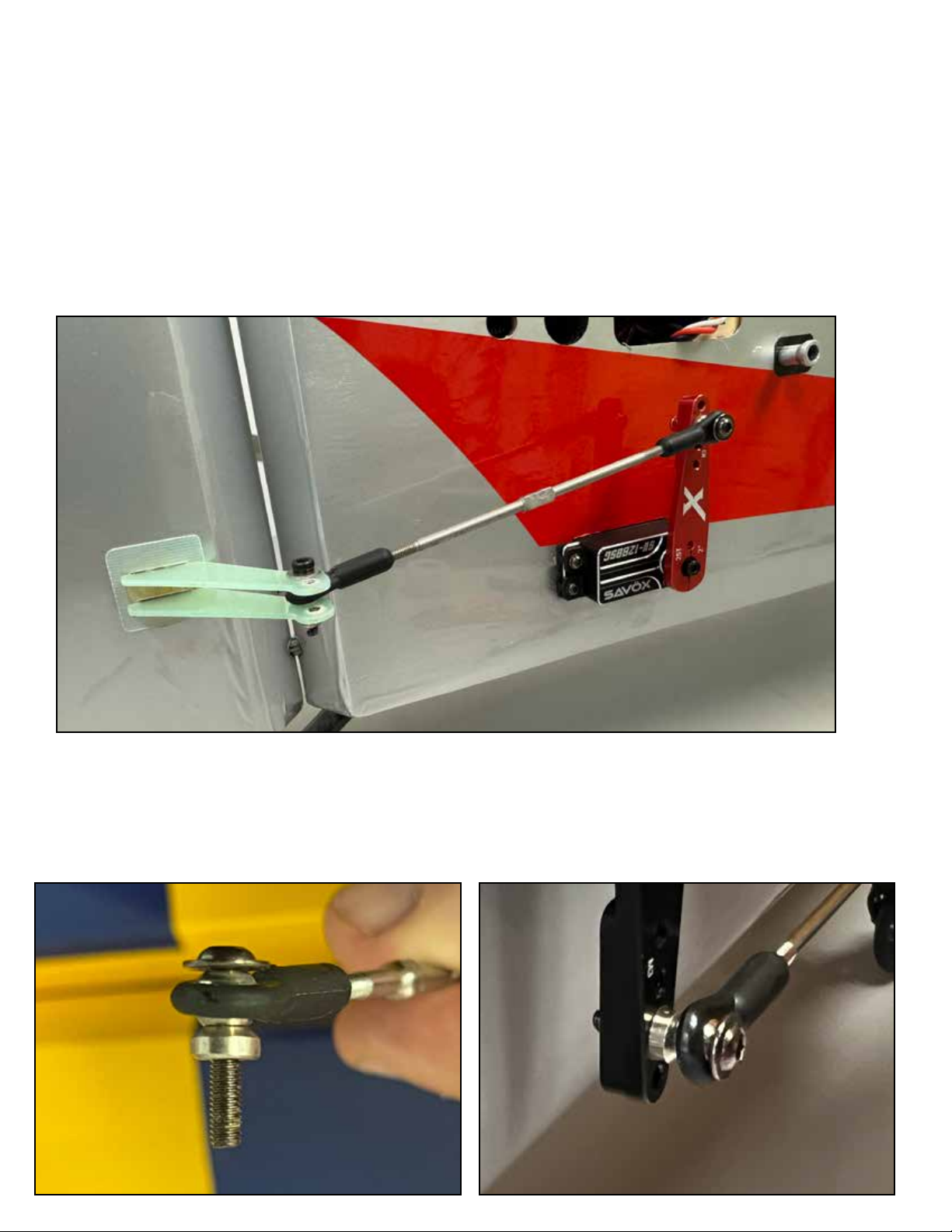
Aircraft in this size class use full-size servos such Savox 1280 or Savox 2290. Be sure to use adequate wire extensions such as
Extreme Flight 20AWG heavy-duty extensions. Check the datasheet for your aircraft, available on the webpage of the aircraft
on the ExtremeFlightRC.com website, for servo arms sizes and extension lengths required. Use a locking clip or masking tape to
prevent the servo wire from disconnecting from the extension in flight. Your kit includes a pre-installed plastic tube in the rear of
the fuselage to provide a path for the extensions to run to the tail.
When doing setup on your radio, maximize the servo travel. If your radio allows 125% or 140% servo travel maximum, use that
maximum value. This should allow you to use the innermost hole on the servo arm. See the photo below. This rudder linkage
uses a 2” Extreme Flight aluminum arm, but by turning the servo travel to maximum, we are able to use the 1.75” hole location
and still achieve the required throw. This results in more eective servo torque, and a stronger system which will respond better
and be less prone to flutter.
On some linkages, a cone-shaped spacer is included if needed. This spacer goes between the ball link and the servo arm to prevent any interference between the ball link and arm. The pushrod has one left-hand anf one right-hand threaded end. This allows
you to spin the pushrod to change its assembled length after installation.
Page 10
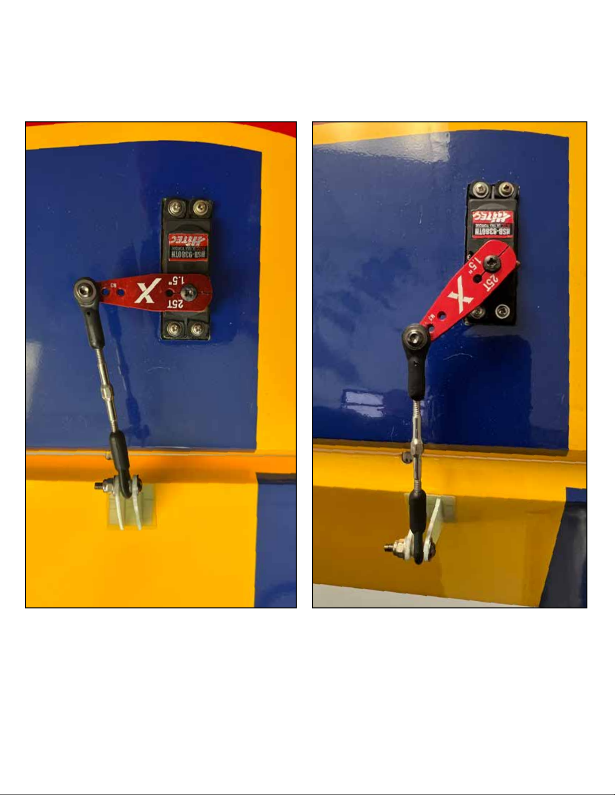
Examine this typical aileron linkage below.
The linkage is “crooked” when the servo is in the neutral position. It becomes “straight” at full deflection. This is by design. It
minimizes side load on the control horn at maximum throw.
Page 11
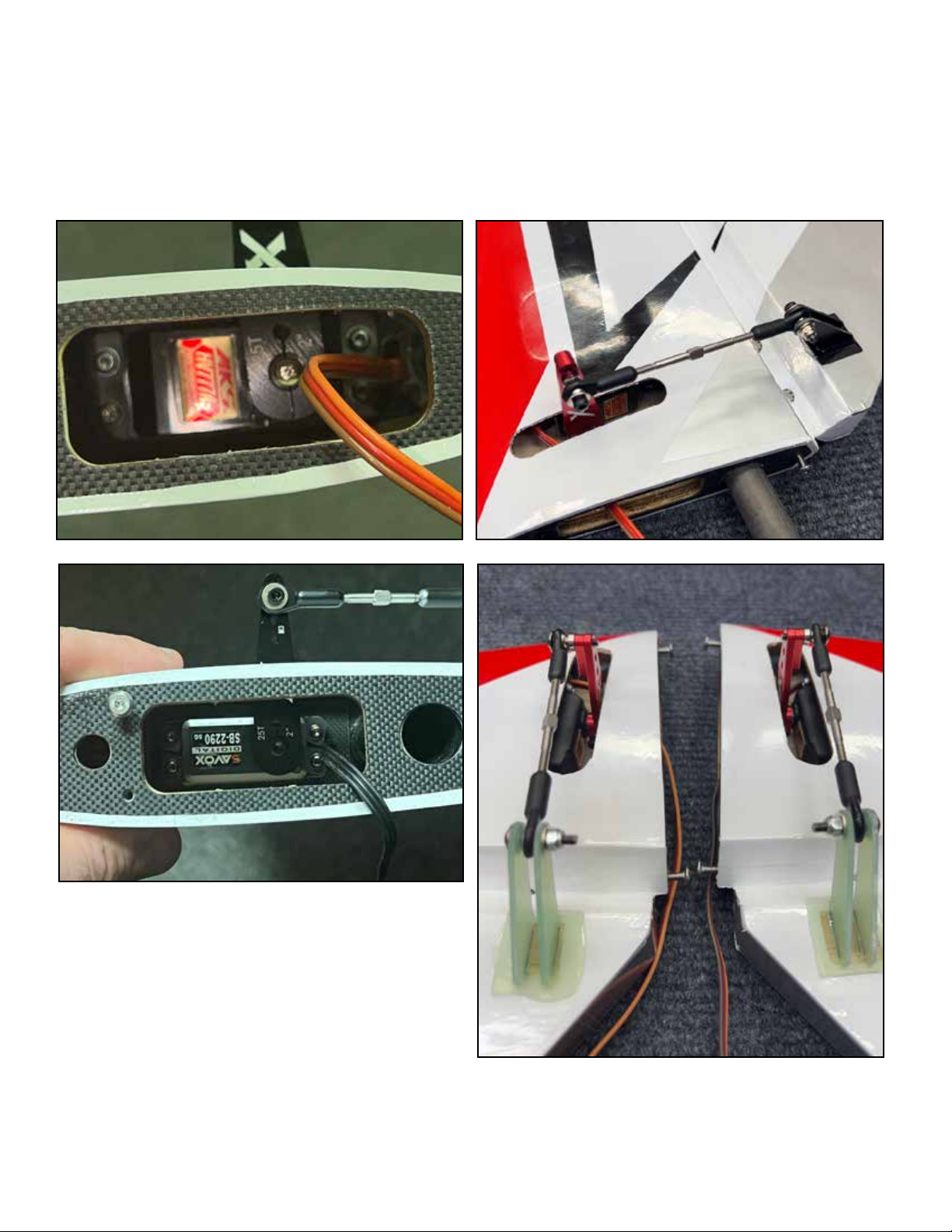
Elevator servos mount inside the horizontal stabilizers as pictured. Often, threading the servo wire into position and seating the
servo will require some patience. Note that the servo orientation will be correct when the servo arm is located in the center of
the slot in the stabilizer.
Install the servo, then install the arm, rotating the servo arm to allow tightening the pinch bolt on the servo arm.
The slots in the stabilizers are cut for the most common servo/arm combinations, but some combinations will require either
shims between the servo and the mount to move the servo, or trimming the slot to widen it.
Page 12
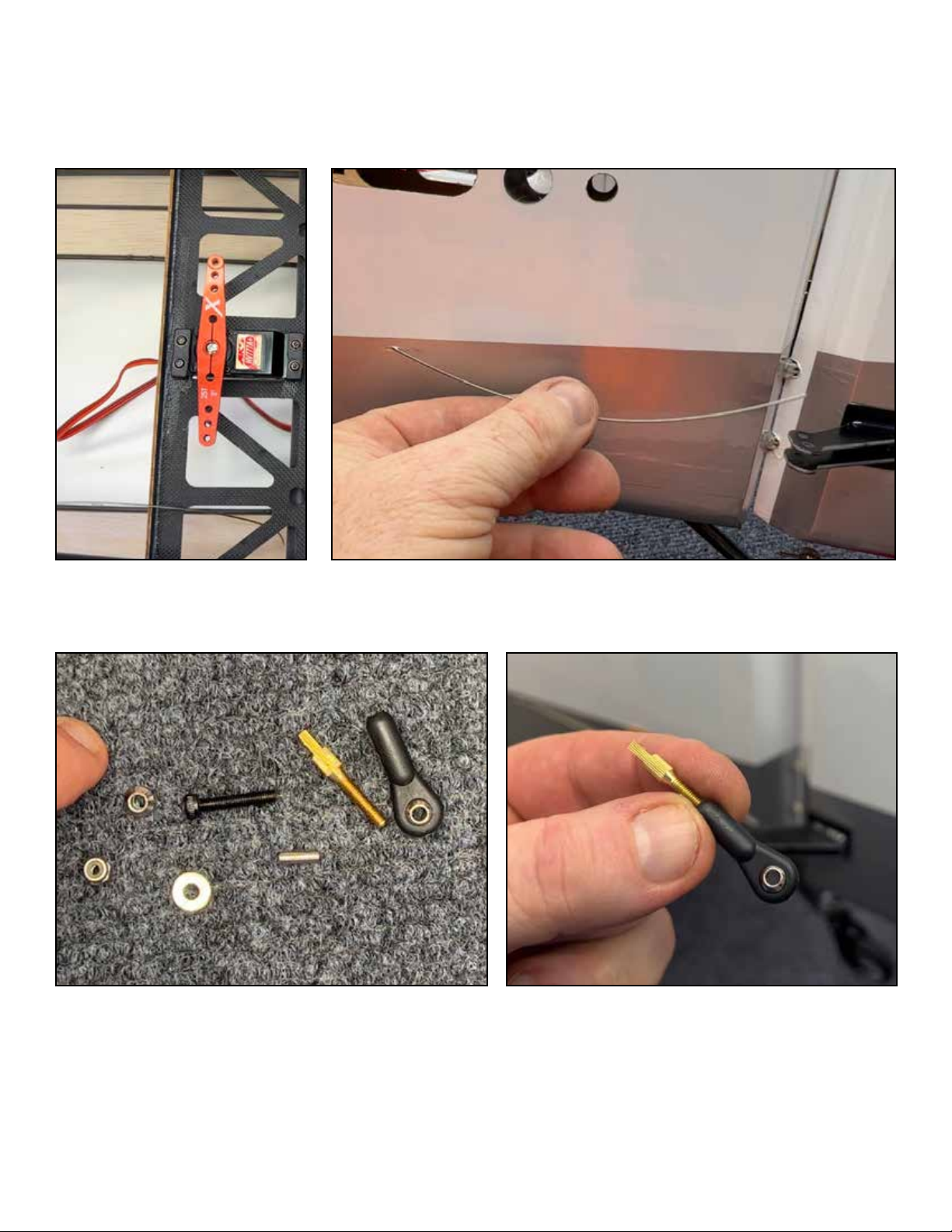
For rudder linkage, if you are using a rear mounted rudder servo, the connection is via a pushrod as on the elevators and ailerons. If you are using the forward rudder servo position for pull-pull rudder, the connection to the rudder is via pull-pull cables.
Start by mounting the servo in the forward location as shown along with its double-sided servo arm. Next, locate the rear cable
exits on the side of the fuselage. Look inside the fuselage, the cable exits have small piece of guide tubing for the cable to ride
inside of. Make a slit in the covering over the exit location and feed the cables into the fuselage and forward to the servo. The
cables cross each other one time to form an “X” shape inside the fuselage.
To terminate the cables at each end, you will use a ball link, a brass threaded end, and the small metal crimp tube. Thread the
ball link onto the brass threaded end, and attach to the servo arm and control horn with screws, washers, locking nuts and cone
spacers as applicable.
Page 13
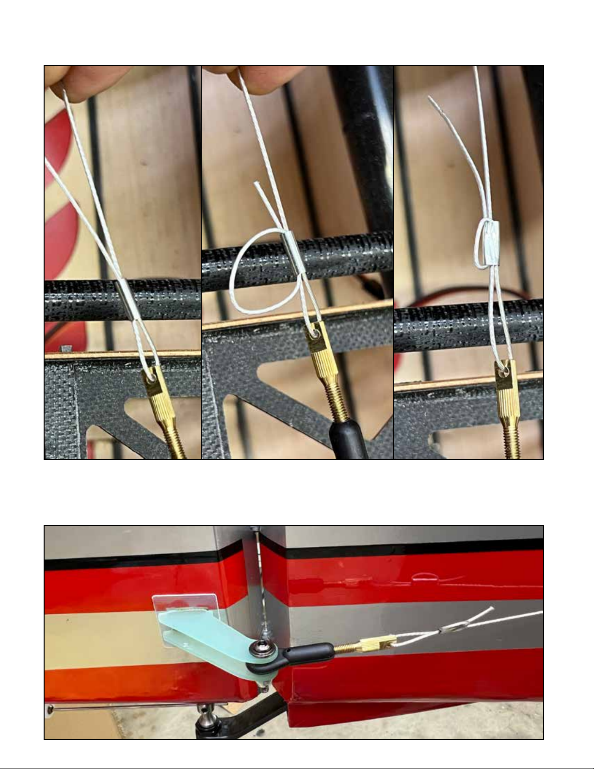
To attach the cables, lace them through the crimp tube and brass end in the pattern shown. Pull the cable snug (not banjo-string
tight) and crimp the tube with pliers to lock the cable in place, and drip one small drop of thin CA into the crimp tube.
After installation, you can tighten or loosen the cables as needed for maintenance by rotating the brass threaded ends to screw
them into or out of the ball joints.
Page 14
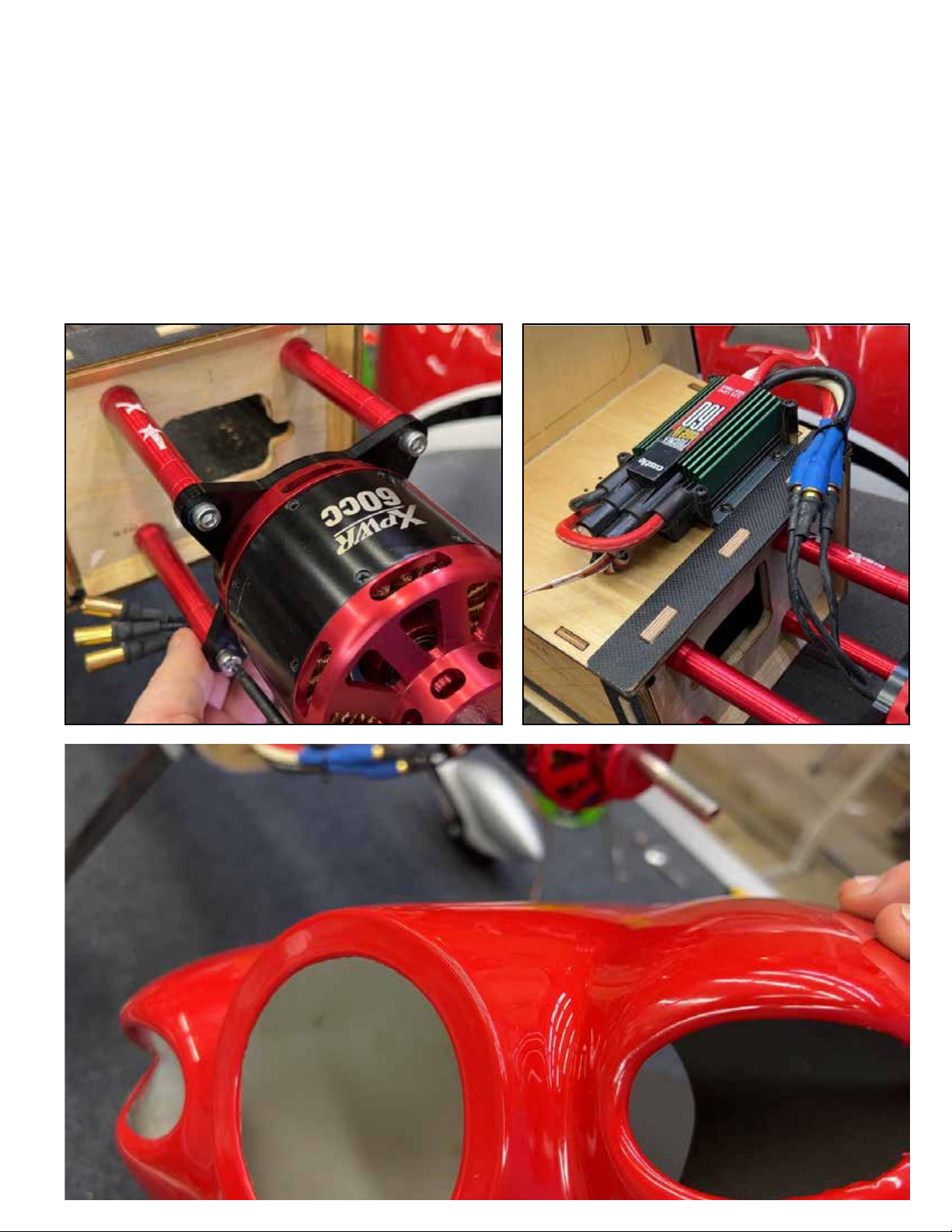
Airplanes in this size class are excellent candidates for electric power with the XPWR60CC brushless motor and 12S 50006000mah lipo batteries. Use our BlazingStar X-Large stando set. The XPWR60CC motor has the same mounting bolt pattern
as the DA-60/DA-70 gas engines. Drill the holes in the firewall on the pre-marked locations, first with a small drill bit such as
2mm or 1/16”, then finish with the final size bit. Use blue loctite on all of the motor mounting screws.
Our favorite ESC for this application is the Castle Creations Edge HV 160. When we introduced the XPWR35-60CC motors, we
worked with Castle technicians to create a compatible firmware for Castle ESCs which was lab tested on these motors. This is
Firmware 4.22. We recommend that you backdate your Castle ESC to firmware release 4.22 using your Castle Link and a computer. This will ensure smooth operation. All other settings remain at default.
It is helpful to put wood or foam baes to channel airflow from the cowl openings directly over the motor and esc. These don’t
need to be complex, but air which flows directly over these components will be much more eective than air which merely flows
close to them.
Page 15
For aircraft in the 85-88” size range we recommend 50-61CC single cylinder gas engines. For aircraft in the 91-93” range, we
recommend twin cylinder 70-76cc engines.
We’ll break down gas engine installation into several steps.
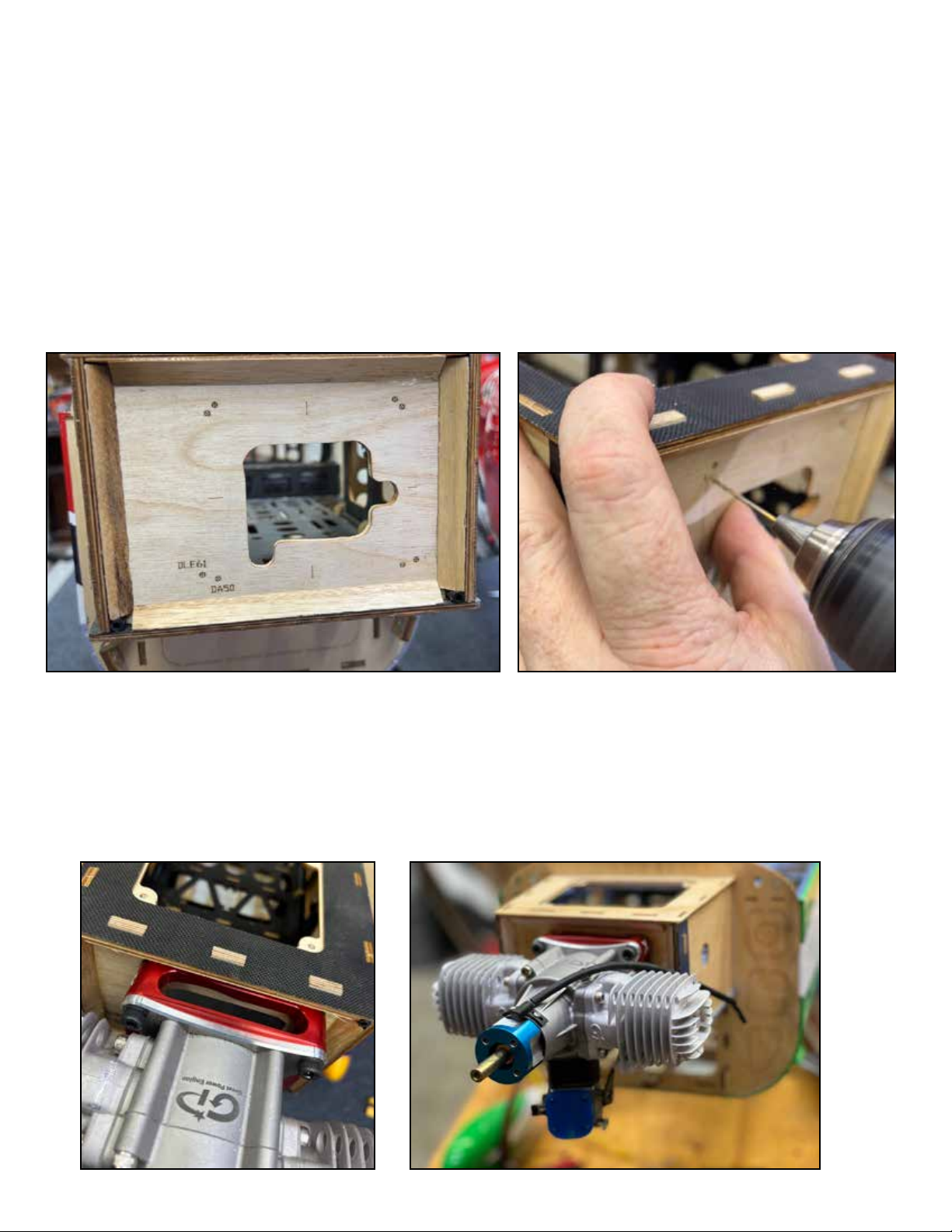
Firewall Drilling
The firewall of your aircraft is marked with a few common engine bolt patterns. Many engines share a common bolt pattern. The
DA 50/60/70 and GP 61/76 share a common bolt pattern. If your bolt pattern is pre-marked, drill on those marks first with a
small drill bit (2mm/1/16) and then finishing with the correct size bit for your motor mounting screws. If your engine has a different pattern which is not marked, consult the engine manufacturer for a pattern which can be printed, and use the centerline
marks printed on the firewall to align your pattern for marking and drilling.
Engine Mounting
We recommend the use of our BlazingStar engine mounts. These mounts are the correct length for our aircraft, they come with
adjustment shims to set the perfect cowl-to-spinner gap (about 2mm), and they protect the crankcase from damage in many
crashes. The firewall of your EXtreme Flight aircraft already has the correct amount of right-thrust and up/down thrust built in,
so there is no need to adjust or shim this in the installation. Use large washers and nylon locking nuts on your engine-mounting
screws to prevent anything coming loose from vibration.
Page 16
Cowl cutting
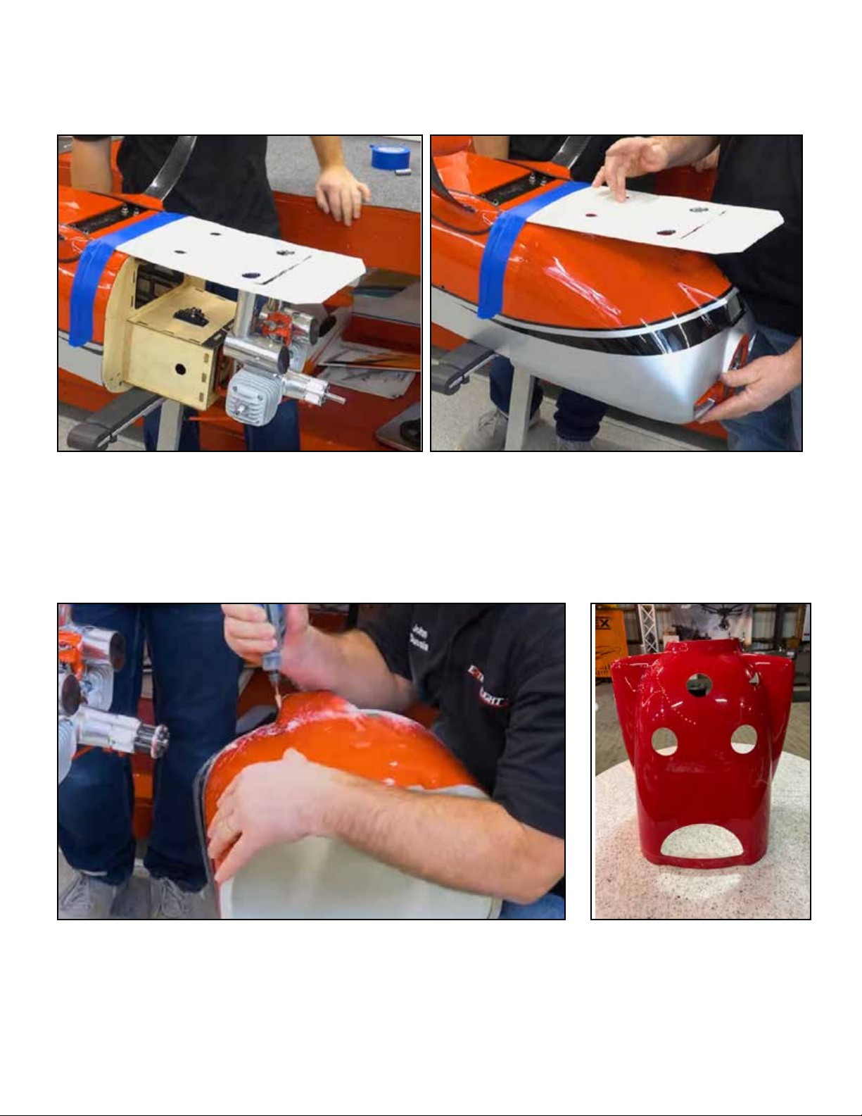
You will need to cut clearance and ventilation holes in your cowl to match the exhaust and/or cylinder of your engine. The easiest
way to do this is to install your muer(s), tape a piece of paper or card stock to the fuselage as shown, and mark the locations
of any protruding muers, pipes, or cylinder. Then, remove the muer or engine, mount the cowl, and use the paper template to
mark the cowl to cut the relief holes.
Once you have marked the locations where pipes and/or cylinder heads will protrude through the cowl, use a Dremel-type rotary
roof to cut these location of the cowl. NOTE: The cowl is made of fiberglass, and the dust from cutting or grinding fiberglass can
be harmful. Wear eye, hand, lung and skin protection when cutting or grinding fiberglass. It’s also recommended to protect electronics and engine internals from fiberglass dust.Test fit the cowl, resume cutting as needed. We recommend also cutting a large
cooling hole at the bottom rear of the cowling if your cowl does not already have this molded-in.
Page 17
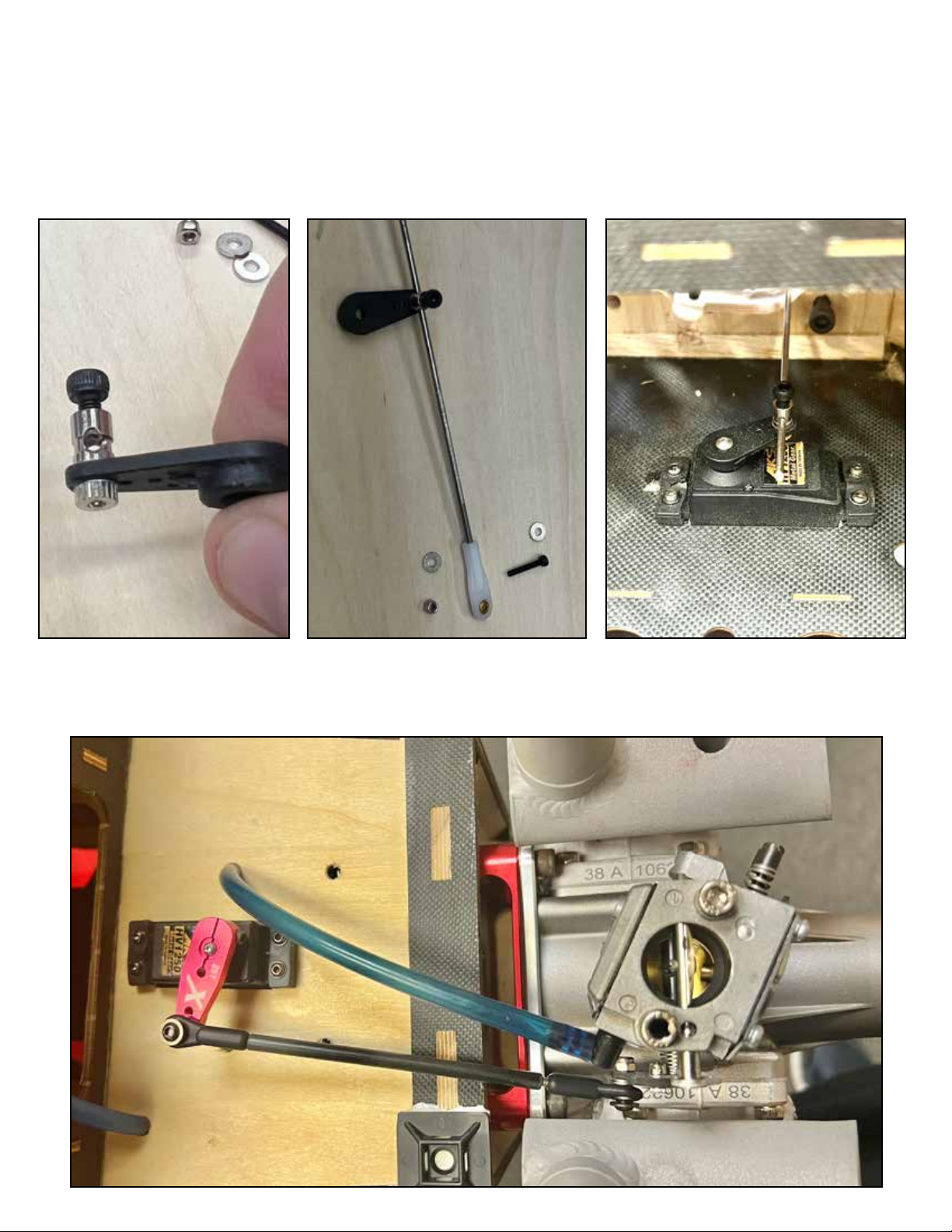
Throttle Linkage
Due to availability of parts, throttle linkage pieces may vary over time in our kits, this is the most common type. There are many
dierent carburetor arm styles, so these instructions are approximate and some creativity may be required in creating your
throttle linkage.
This type of connector is a common one for our linkage, it attaches to the servo arm by tightening the clinch nut so that the
barrel of the connector is still free to rotate, and placing a drop of medium CA glue on the nut to stop it backing o. Pictured is a
typical single-cylinder throttle installation, with the servo inside the motor box.
If your engine and its carburetor and throttle arm allows it, it is an upgrade to use a 1” metal servo arm on the throttle servo,
and to use a throttle pushrod with ball links at each end. Pictured is a typical twin-cylinder throttle installation, with the throttle
servo on the outisde/bottom of the motor box.
Page 18
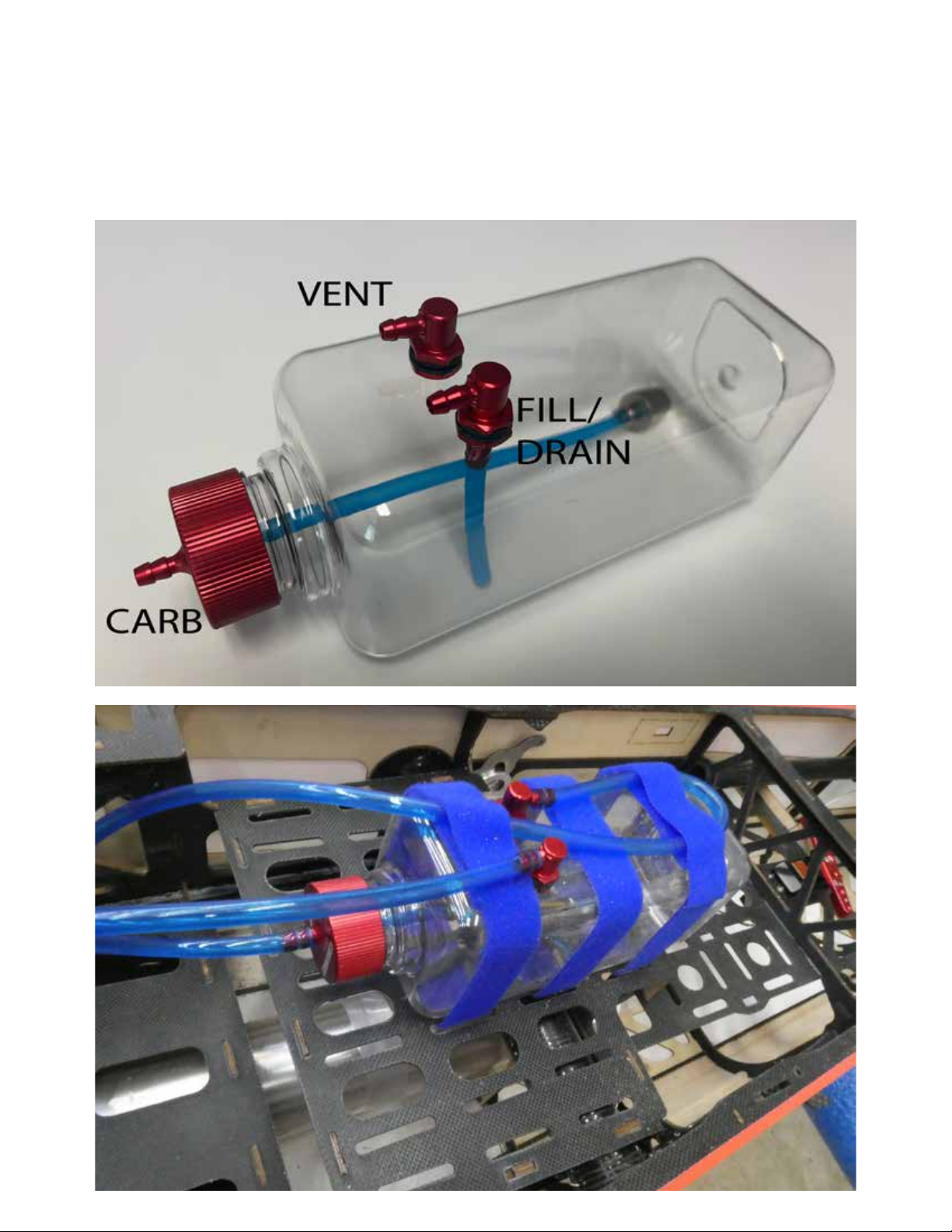
Fuel Plumbing
For plumbing your aircraft, we recommend Extreme Flight Flowmaster fuel tanks, fuel line, and fuel dot connectors. There are
three primary connections on your gasoline fuel system: Fuel clunk to carburetor, fill/drain line to fuel dot, and vent. Extreme
Flight fuel tubing is designed to grab onto barbed connections, and so zip ties or wire ties to secure fuel connections are optional. Note that the vent line has a loop in it to prevent siphoning fuel during flight, and the vent exits the airplane on the bottom of
the cowl.
We attach the fuel tank to the tray in the fuselage with self-adhesive velcro and two strong velcro straps. Typically, the fuel tank
is located at the rear of the front tray, as close to the center of gravity as possible.
Page 19
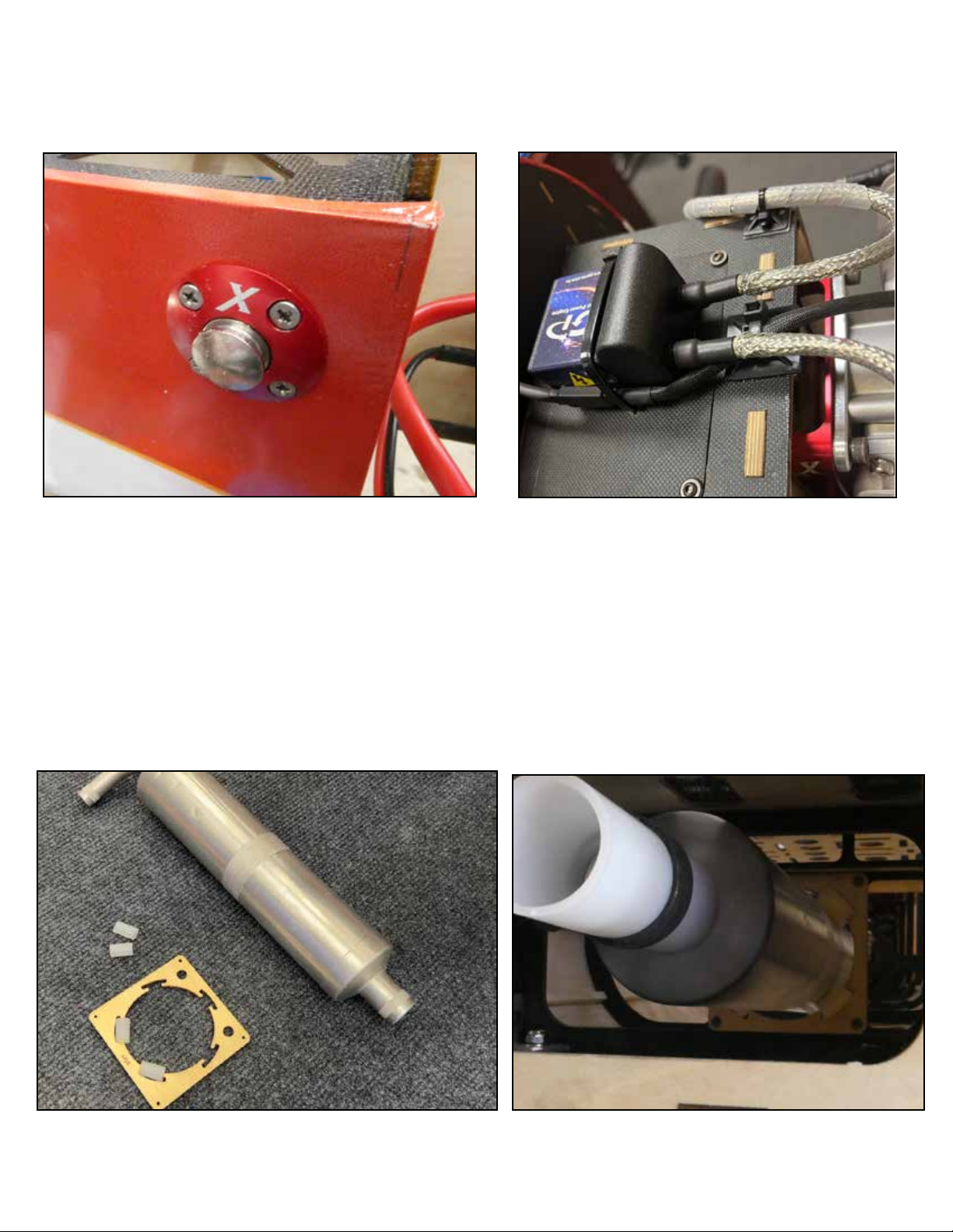
Locate your fuel dot in the fuselage side as shown. Mount your ignition to the motor box as shown, and arrange power for your
ignition. We prefer an IBEC, such as the Tech-Aero IBEC unit or the AR (Advanced Radio) IBEC unit.
Exhaust
Most of our aircraft in this size range have provisions and a mount for a canister or tuned-pipe exhaust. There are many dierent
sizes and shapes of cans and pipes, some custom fitting may be necessary. The bottom of the fuselage of most of our aircraft
has either pre-cut cooling and exhaust outlet holes under the covering, or the kit includes laser-cut outlet plates which attach to
the bottom with screws. Open these outlets as appropriate for your exhaust system.
Page 20
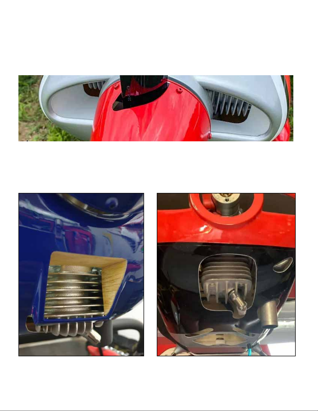
Gas Engine Cooling
Gas engines are cooled by air passing over and between the cooling fins on the cylinder.
For twin cylinder engines, the primary cooling air comes in through the air inlets on the front of the cowl. It can be helpful to
arrange baes or flow directors which cause the air to pass directly over the cylinders. We are adding fiberglass cooling ducts
to more of our kits each year. These install by gluing to the cowl with epoxy glue. If your kit does not include fiberglass ducts, to
form baes or deflectors, we often use EVA FOAM sheet, also called COSPLAY FOAM. This inexpensive, resilient foam is available from art supply and craft stores, and from retailers like Amazon. 2mm and 3mm thickness are the most useful.
For single cylinder engines, cooling air primarily comes in through the front of the cowl at the bottom. It can be helpful to make
a duct out of wood or foam as shown. For both single and twin cylinder engines, once the air passes over the cylinder head, it is
exhausted out of the bottom of the cowl through an air exit opening. If additional airflow is needed, there are various vents which
can be opened up on the bottom of the aircraft. It is a good rule of thumb to have 3-4 times the exit area compared to the inlet
area for your cooling air.
PHOTO CREDIT JOEL WHITBURN PHOTO CREDIT JEFF HUGHES
Page 21
Mount your receiver on the tray behind the wing spar tube. Mount a switch into the fuselage side if you use one. Install the
batteries to power your radio system.
The stabilizers mount onto the fuselage with one or two carbon tubes and latch in place. When you plug in the servo wires, use a
clip to prevent them coming unplugged in flight. The wings similarly attach with one or two carbon tubes and latch in place. Use
a clip on the aileron servo wire.
Set the control throws according to the data sheet for your aircraft, available on that airplane’s page on the ExtremeFlightRC.
com website. Be sure to add adequate EXPO and be sure each surface is moving in the correct direction. There are various
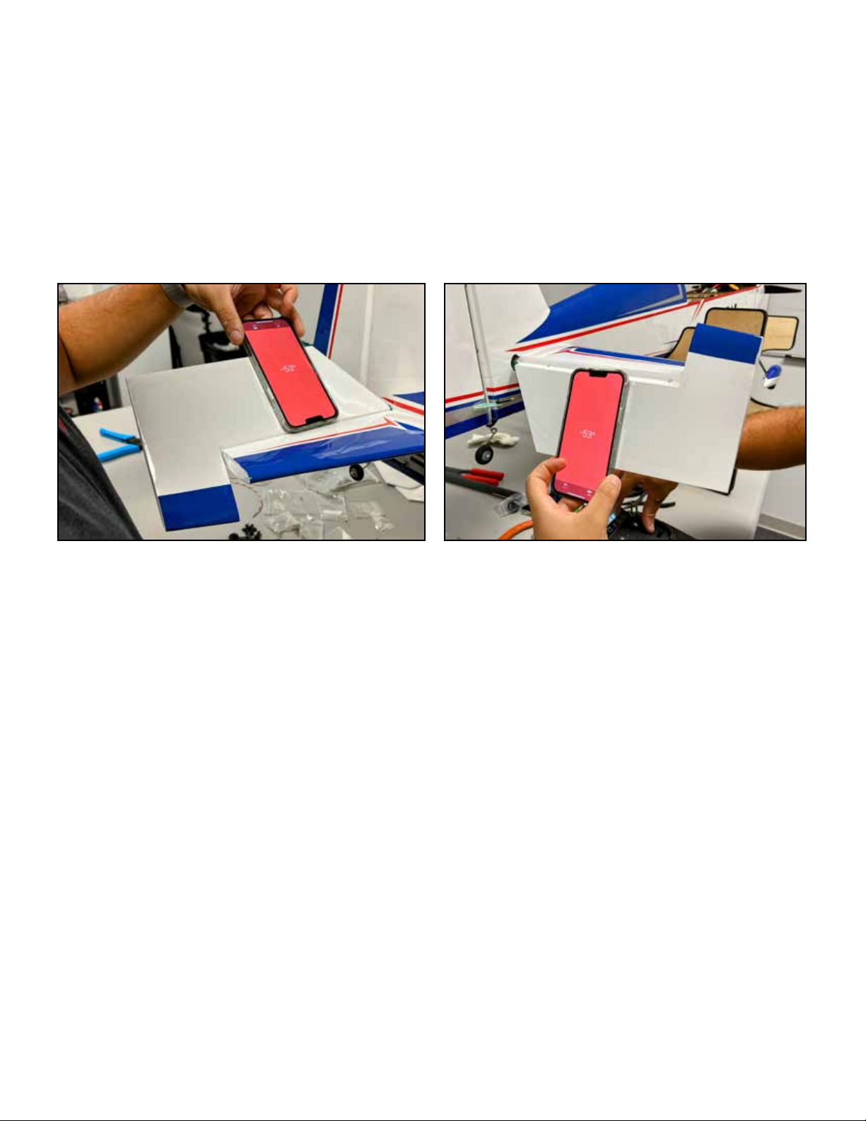
kinds of throw-meters available for this purpose, but our favorite is the smart phone most of us carry every day. Use a “level” app
(most phones come equipped with one) and hold the phone against the control surface to measure deflection.
Check all fasteners for tightness. Drill and balance your prop (or better yet, get a pre-drilled and pre-balanced prop from ExtremeFlightRC.com) and install it according to the engine manufacturer’s instructions. Run your power system on the ground
using proper and safe restraints. Set your gas engine’s carburetor settings according to your engine manufacturer’s instructions.
Balance
Aerobatic monoplanes in this class from Extreme Flight are very insensitive to CG location. If you are using recommended
equipment, it is not necessary to balance the aircraft if you want a 3D/aerobatic CG, they have been thoroughly tested with the
recommended components. For 3D flight, the balance point will fall behind the main wing tube, and the aircraft will hang taildown while being supported by the main wing tube.
A 3D/aerobatic CG is rearward of a precision flight or training CG. If you are a less-experienced pilot and you would like to have
a more stable, nose-heavy CG for your first flights, this is a good idea and easy to achieve. A good training CG for these aircraft
is measured by supporting the aircraft by the main wing tube with the wings installed, and fuel tank empty (if electric, lipo
batteries should be installed). For a training CG, the aircraft should hang level. You *could* move equipment forward to achieve
this, but since the goal is to progress to an aerobatic CG once you are comfortable handling (and especially landing) the aircraft,
we recommend simply adding some temporary nose weight to the aircraft. We use plasticine modeling clay (commonly available
non-drying clay for kids) which is inexpensive and dense. You can easily and safely mold it into the interior of the motor box at
the front of the fuselage. Expect to use several ounces to move the CG forward to the training location at the center of the wing
tube.
An aircraft at the training CG location will be less maneuverable, it will be very easy to land, and it will be quite dicult to fly 3D
maneuvers with. As you gain confidence with the aircraft, remove clay and move the CG back and it will become more maneuverable and more capable of 3D flight.
We hope you enjoy your aircraft, and please contact us if you have any questions or problems.
 Loading...