

Extreme Flight EXTRA 300EXP Assembly Manual
EXTRA 300EXP
Electric ARF
1

Greetings and congratulations on your purchase of the Extreme Flight RC
Extra 300EXP ARF
. Loosely based on our favorite variant of the Extra, the
mid-wing Extra 300, we have taken numerous liberties with this design to
produce an aircraft that is both unique in appearance and flight ability. The
designation 300EXP does not belong to a full scale Extra, but stands for
Experimental Progressive. This name was chosen due to the fact that from its
inception the Extra 300EXP was developed as a test bed for several new
forward thinking design and aerodynamic concepts. Having spent several
months in development, flight testing and refinement, we are very excited
about the end result of our quest.
The Extra 300EXP incorporates carbon fiber and G10 composites into the
structure of the airframe, resulting in a lightweight, yet twist free structure
capable of handling extreme aerodynamic loads. Carbon and G10 are used in
high stress areas such as motor box support, landing gear mounting structure
and fuselage longerons to provide enormous strength and durability. A true
piece of carbon fiber art, the landing gear is airfoiled and has just enough
"give" to cushion those not so perfect landings. The removable wing panels
are mounted on a carbon fiber wing tube and are fastened to the fuselage with
nylon thumbscrews. The large canopy (which is retained by a spring loaded
hatch latch) has been moved forward to place the tallest portion of the aircraft
at the center of gravity, resulting in the best knife edge performance of any
aircraft we've flown to date. The airfoiled tail surfaces are built using a
unique geodetic construction technique which allows the use of less material
while creating a structure that is superior in strength and rigidity to typical
ARF construction methods. All control surfaces are pushrod driven with short
linkages and use ball links for slop free actuation with no binding. Optional
Side Force Generators are included and add to the already generous side area,
increasing yaw axis authority and adding stability in all angles of sideslip.
Expertly painted fiberglass cowl and wheel pants and 2 gorgeous high
visibility Ultracote color schemes add the finishing touches and make this an
airplane that you will be proud to show up at the flying field with. The
combination of these unique elements add up to an aircraft that pushes the
boundaries of modern aerobatic flight.
If repairs become necessary, the Ultracote colors used on the Extra 300EXP
are as follows:
Blue color scheme: Deep Blue/White/Black/Silver
Red color scheme: True Red/White/Black/Silver
2

Tips for Success:
1. Before starting assembly, take a few minutes to read the entire instruction
manual to familiarize yourself with the assembly process.
2. Please take a few minutes and go over all the seams on the aircraft with a
covering iron on a medium heat setting.
3. Use a fresh bottle of thin CA with a fine glue tip when attaching the CA
hinges. This will ensure that the proper amount of CA wicks into the hinge
and surrounding balsa wood and creates a proper bond between the wood and
hinges. We are big fans of the Mercury line of adhesives as well as the glue
tips provided by them.
4. Apply a couple drops of CA to high stress areas such as anti-rotation pins,
landing gear mounts, servo trays and motor box support mounts.
5. All of the G10 control horns are the same with the exception of the elevator
horn. Its base has been shortened to fit the width of the elevator.
6. When applying decals, first clean the area where the decal will be applied
with alcohol. Mist the area lightly with Windex before applying the decal
which will allow you to properly position it, then use a rubber squeegee to
push all of the liquid from under the decal. This will result in very few air
pockets trapped under the decal.
7. Take the time to properly balance and trim your aircraft and set up rates
and exponential values. Your flying experience will be greatly enhanced by
doing this.
3

Items needed for completion
-masking tape
-Thin and medium CA. We highly recommend Mercury M5T thin and M100XF medium
formulas as well as the Mercury glue tips.
-30 minute epoxy. I have used Pacer Z-Poxy for many years and it is a terrific product. It
cures in the allotted time and forms a permanent bond.
-Blue Loctite.
-Silicon based glue (Zap-A-Dap-A-Goo, etc.)
-Electric drill with an assortment of small drill bits.
-Small flat head and Phillips head screw drivers.
-Standard and needle nose pliers.
-Metric balldriver or allen key set.
-4 sub micro metal geared servos. All flight testing was performed with Hitec HS-65MG
and HS-5065MG digital servos and we strongly recommend the use of either of these high
quality servos.
-Torque 2818T/900 or 2814T/820 Brushless Outrunner motor.
-Airboss Elite 45 Amp ESC.
-4S 2100-2700 mah LiPo battery. Our favorite batteries in this aircraft have been the
FlightPower EON Lite 2550. We've also had great success with the Zippy Rhino bargain
LiPos available from www.hobbycity.com in both 2170 mah and 2350 mah sizes.
-APC 12x6 E prop (NOT the slow fly version!).
-52mm Extreme Flight spinner.
-2 18"-24" extensions for the 2 rear servos and 2 6"-8" extensions to go between the
receiver and the aileron servo leads. We recommend the 28 or 32 AWG extensions to save
weight.
-Adhesive backed Velcro and Velcro strap for battery retention.
4
Highlighted text has been changed. Please note new procedure on the right of the page
Let's begin!
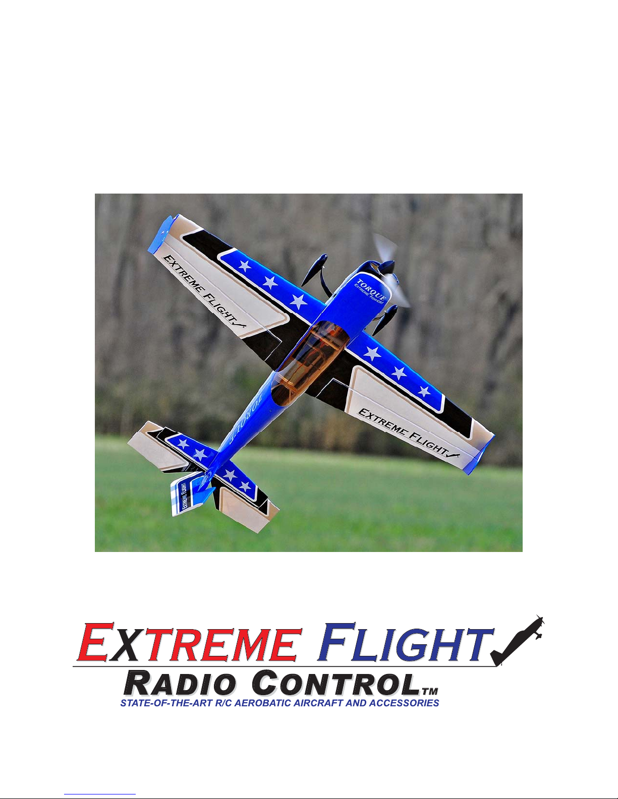
1. So that we don't have to wait for the 30 minute epoxy to dry in a later step,
let's go ahead and prepare the 4 carbon fiber pushrods and ball links for later
use. Locate the 4 carbon fiber pushrods and 4 micro ball links in the
hardware package. Lightly scuff one end of each pushrod.
Note: Based on Customer Feedback
and field testing we have changed the
control rod process. Locate the
threaded pushrods and the micro ball
links along with 2mm screws, nuts
and washers. Thread the ball links
onto each end of the pushrods and
when you reach the appropriate step,
secure to the servo arm and control
horn with the 2 mm hardware. For a
slop free setup we no longer use the
EZ Links
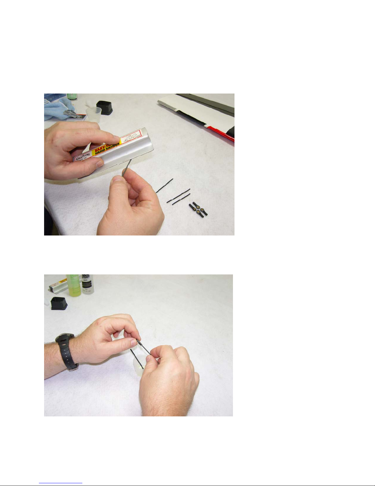
2. Mix up a small batch of 30 minute epoxy. Dip the scuffed end of each
pushrod into the epoxy and i
nsert this end into the ball link with a twisting
motion to make sure the epoxy is evenly distributed inside the ball link. Make
sure the pushrod is completely inserted into the ball link.
5
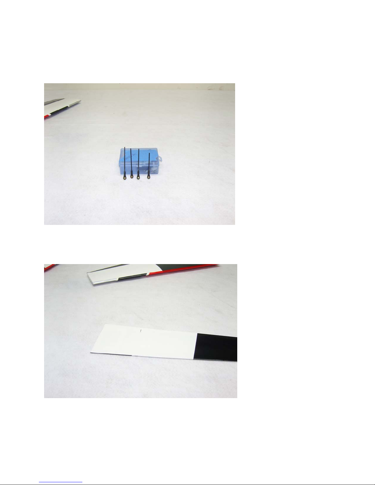
3. Use a paper towel to wipe away most of the excess epoxy, leaving a small
fillet between the carbon pushrod and ball link. Position the pushrods
vertically while they cure as illustrated so the fillet remains in position. DO
NOT use CA for this bond!
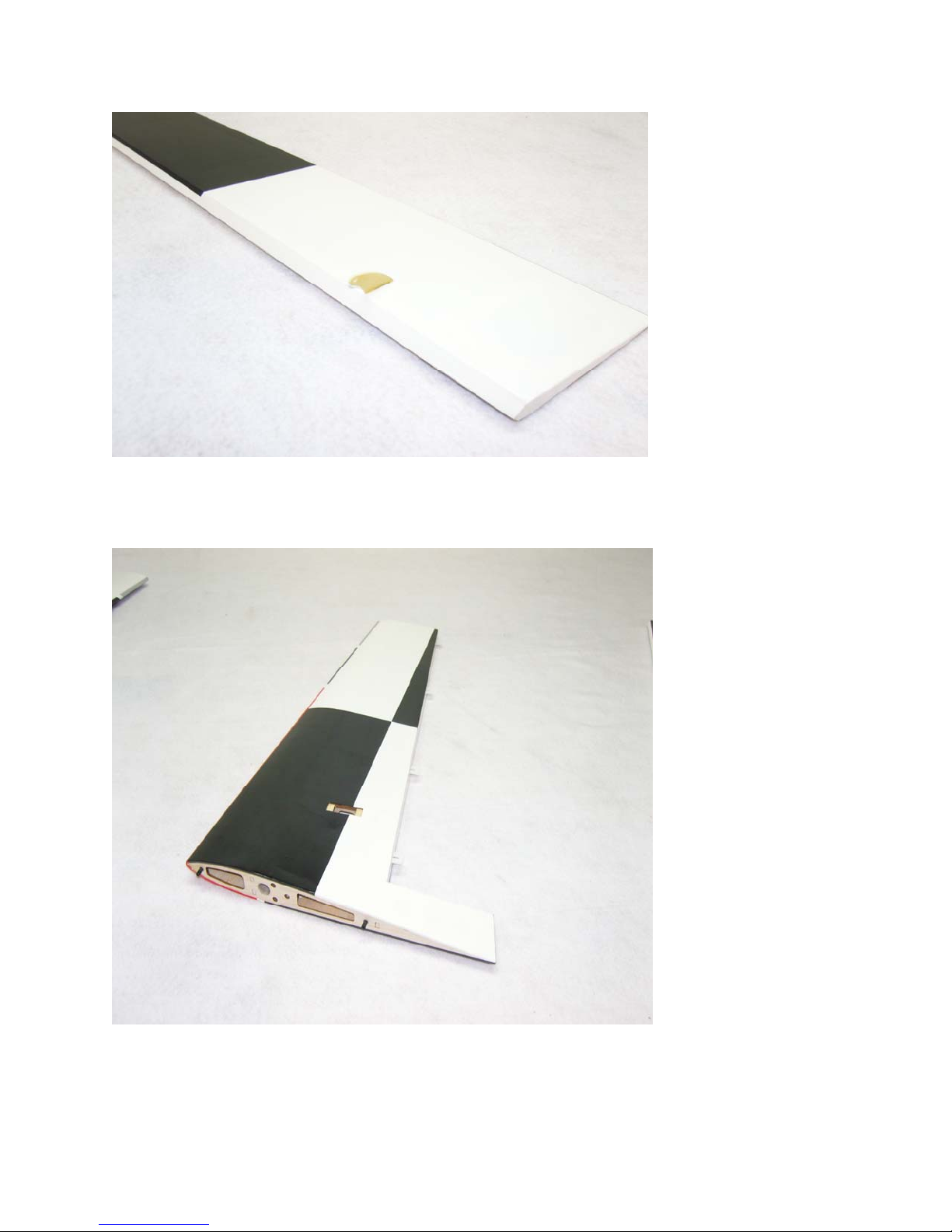
4. Locate the 2 w
ing panels with ailerons as well as the 2 G10 aileron control
horns. Remove the ailerons from the wing and remove the covering over the
slot for the aileron horn on the bottom of the aileron with a sharp hobby
blade. Make sure you are doing this on the bottom of the aileron!
5. Scuff the portion of the control hor
sandpaper.
n that will be glued into the aileron w
6
ith

6. Use a glue tip on your bottle of medium CA and apply glue to the slot as
well as to both sides of the control horn. Insert the control horn into the slot
and make sure it seats properly against the surface of the aileron.
7
7. Remove the covering from the aileron servo location and make sure the
hinges are centered in their slots.
8

8. Slide the aileron into position on the hinges and secure with several drops
of fresh thin CA. This process is much easier and more effective if a fine glue
tip is used. Make sure to deflect the surface as pictured while applying the
CA.
9. Use the screws provided by the servo manufacturer to secure the aileron
servo in the designated location. 1 screw installed in the center hole at each
end of the servo is adequate to secure the servo. Make sure the output shaft is
positioned toward the trailing edge of the wing.
9
 Loading...