

Page 1
EXTRA 300-E
58” ELECTRIC ARF
Instruction Manual
©Copyright 2007 EXTREME FLIGHT RC, Ltd.
Page 2

Congratulations on your purchase of the Extreme Flight RC Extra 300 58 inch Electric
ARF. This aircraft was designed to provide maximum performance and fun in a great
looking, lightweight, easily transported, fully aerobatic ARF aircraft. Using a powerful
and efficient brushless outrunner motor and speed controller and a single high discharge
5S1P Lithium Polymer battery (3300-5000 mah), the 58 inch Extra provides unlimited
precision and 3D aerobatic performance capability.
Great care was taken to design a light weight yet robust airframe. Expert engineering
and modern laser cutting methods in conjunction with a carbon fiber wing tube and
composite control horns keep weight to a minimum. Unique features such as the 2 piece
plug in wings mounted on a carbon fiber wing tube, pre-mounted canopy and spring
loaded canopy/hatch latch make for quick easy assembly and instantaneous access to the
interior of the plane and battery tray. The Extra also features a high quality set of carbon
fiber landing gear, PILOT X series helmet head pilot bust and detailed dash/instrument
panel. Getting the Extra in the air is quick and easy! The Extra can truly be assembled in
a couple of evenings-buy it on Friday, fly it on Sunday!
As with all Extreme Flight RC airplanes, fight performance is second to none! The
Extra flies precision aerobatics remarkably well and allows you to practice your IMAC
sequences almost anywhere. The long tail moment makes for a plane that tracks like a 2
meter pattern ship and the lightweight wings minimize over rotation in snaps. You’ll be
amazed at how well this thing flies the sequences.
Of course the Extra will perform all of the 3D moves with ease. Incredible yaw, pitch
and roll authority allow the Extra to obey your every stick command. Sport flyers fear
not! With reduced rates the Extra is a very easy plane to fly. Its super light wing loading
allows it to land at a walk. It will instill confidence and allow you to improve your flying
skills. When you’re ready for more advanced aerobatics, flip the dual rate switch and
hang on!
As with any high performance aerobatic aircraft, great care must be taken to avoid
excess speed. Excess speed could lead to control surface flutter and quite possibly the
complete destruction of your aircraft. Don’t let this happen to you! Always have the
motor at idle when the airplane is pointed down and reserve full throttle for vertical
climbs. Make sure you have adequate mechanical advantage in your control linkage setup. If you are unsure about this, have a more experienced flyer look over your set-up
before flying. Extreme Flight RC, Ltd. in no way warranties its aircraft against flutter.
As with all of our planes, we put the Extra through a rigorous flight testing regime and
have not experienced any control surface flutter. It is your responsibility to ensure the
airworthiness of your aircraft.
The 58 inch Extra was designed around the new Torque Revolution 4014T/570
Brushless Outrunner motor and Airboss Elite 80 Amp ESC with SBEC. This is the best
choice for powering the Extra, providing plenty of power for any maneuver imaginable.
Other outrunner motors in this class will work as well but may require slight modification
to the motor mount. We also recommend the use of the Hitec HS-5245mg digital mini
servo for aileron and elevator. The standard HS-225MG is also a good choice. We used
a standard size digital servo for rudder (Hitec HS-5475). The HS-475 is also a good
choice. Please take a few minutes to read this manual before beginning assembly to get
familiar with the process.
2
Page 3

Tips for Success-Please read before beginning assembly!!!
1. Read the instruction manual thoroughly before starting assembly.
2. We are very pleased with the level of craftsmanship exhibited by the workers
in our factory. However, these are mass produced models. As with any ARF,
take a few minutes to go over the model and add CA to high stress areas or
any joints that appear to need more glue. Specific areas to pay attention to are
servo mounts, landing gear mounting plate, firewall to fuselage side joint,
wing root rib and motor box joints. A few minutes and a few drops of CA
will help to insure the longevity of your model.
3. Make sure your prop and spinner are balanced! These aircraft perform as well
as they do because they are built light. Excess vibration caused by unbalanced
components can cause damage to the airframe.
4. Buy a Watt meter! For less than the cost of a single battery pack you can
purchase one of these. This will save you a lot of time, money and frustration
and provide you with a lot of valuable information about your set up. One
battery pack saved is worth this investment!
5. Observe the C rating of your batteries. For example if your battery is rated at
2100 mah and 20C continuous discharge rate then you can safely pull 42000
mah or 42 Amps from it (2100 x 20= 42000 mah=42 Amps). Use a watt
meter between your battery and ESC to determine the number of Amps you
are drawing as well as the number of Watts you are generating. I have found
it is best for battery longevity if your maximum amp draw at wide open
throttle is in between the continuous rating and the burst rating of the battery.
Prop your airplane accordingly.
6. We have done a lot of experimenting with various props. Using the Torque
4014T/570 on 5S we like the APC and XOAR 14X7 and 15x8. Depending on
your elevation you may or may not like these choices, but they should be a
good starting point. Remember to test each new prop with a Watt meter
attached to the system to be sure you are not overworking any of the
components.
7. Decals- clean your airplane with glass cleaner and a paper towel before
starting to apply the decals. Mist the area where the decal will be applied with
glass cleaner or water mixed with a little bit of soap. Use scissors to remove
the decal from the sheet. For best results cut as close to the edges of the decal
as possible. Position the decal in place and use a credit card or rubber
squeegee to push the excess liquid from under the decal and allow to dry.
You may need to secure the edges of the decal with masking tape to prevent
them from rolling up until the solution has dried and evaporated.
3
Page 4
Wing assembly
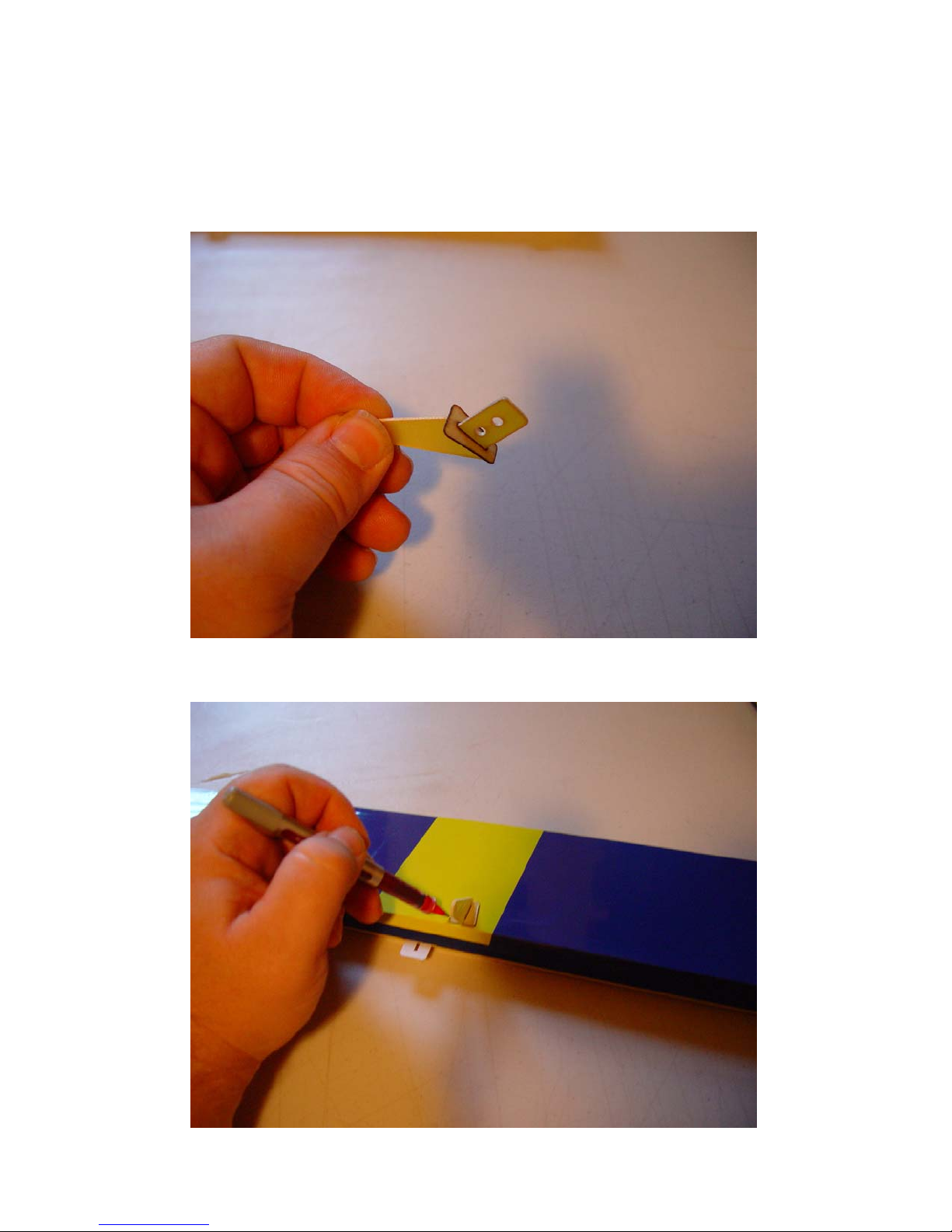
1. Locate one of the aileron control horns and its mounting base. Remove one of the
ailerons from the wing, making sure to keep track of the CA hinges
2. Use a sharp hobby knife to open the slot for the aileron control horn on the bottom
of the surface. Insert the control horn into the base and into the slot in the aileron.
Use a fine tipped felt marker to outline the base of the control horn.
4
Page 5
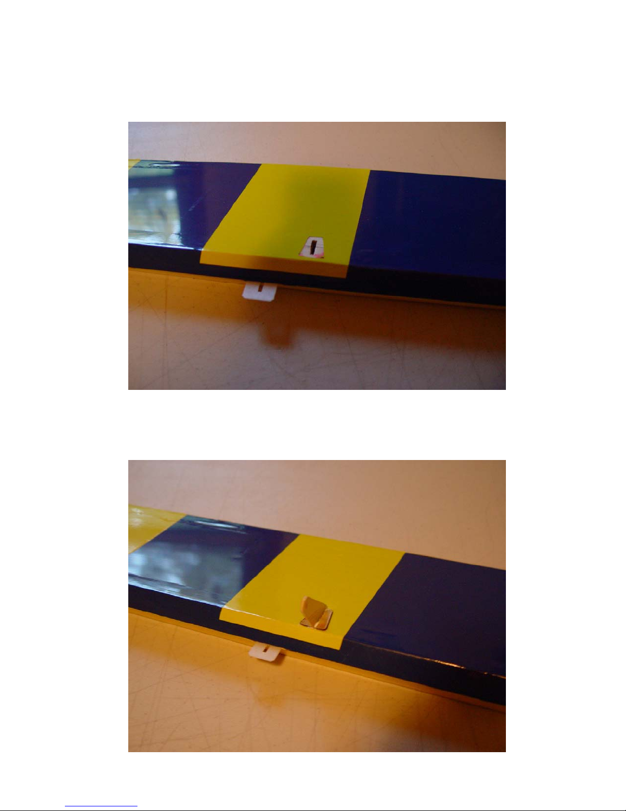
3. Remove the control horn and use your knife to remove the covering where the
base will be glued.
4. Scuff the part of the control horn that will be glued into the aileron slot with
sandpaper. Mix up some 30 minute epoxy and apply to the slot and control horn
and its base. Insert the control horn and base into the slot and push down until the
horn is properly seated against the base and aileron surface. Wipe any excess
epoxy away with a paper towel and some denatured alcohol.
5
Page 6
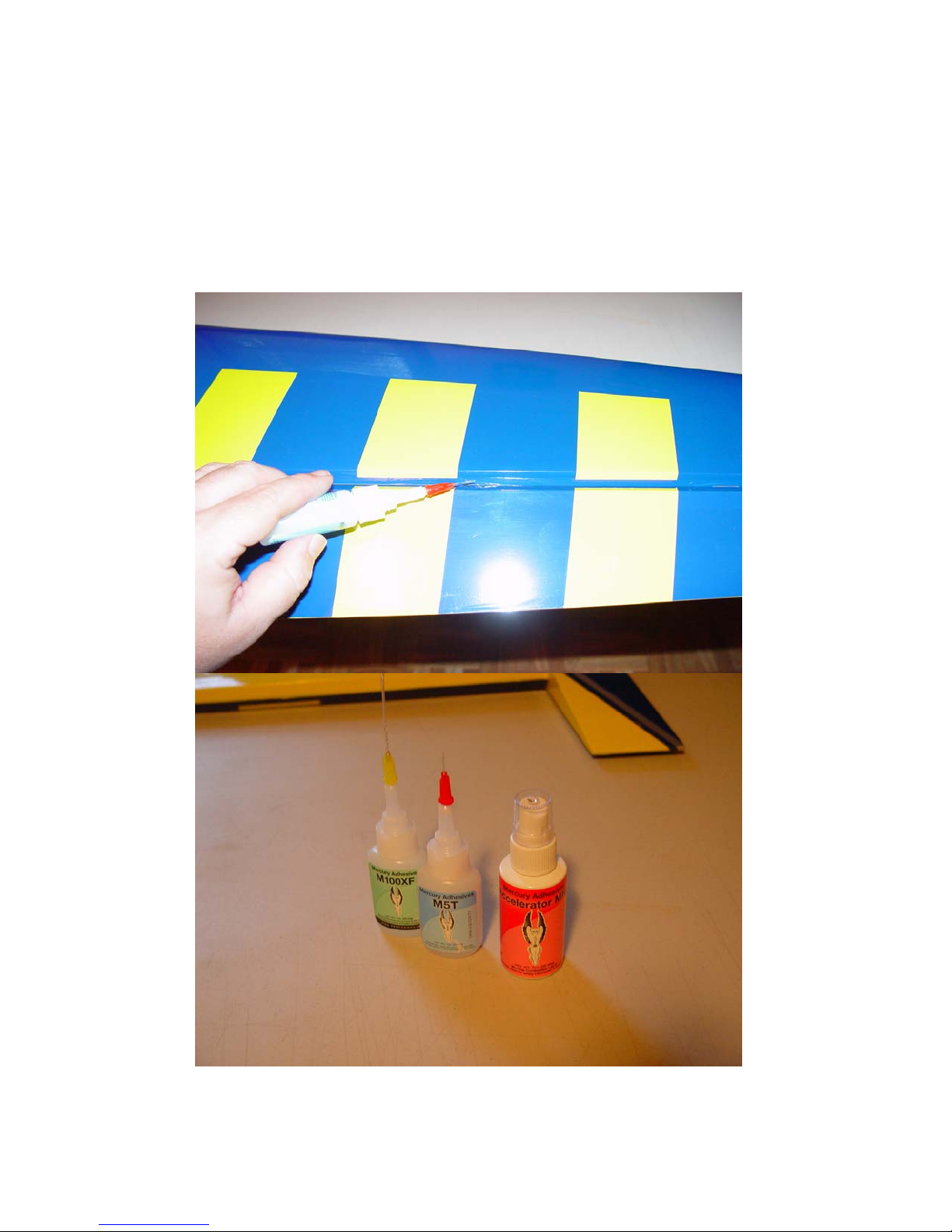
5. Place the aileron back on the wing, making sure the hinges are centered between
the aileron and wing. Deflect the control surface to full deflection. Use thin CA
and a fine tube applicator to apply a couple drops to each hinge. I’ve recently
become a convert to the new Mercury adhesives and the M5T thin viscosity
formula works great for CA hinges. Mercury also sells an assortment of Teflon
tips which make the application of just the right amount of adhesive very easy.
The assortment includes a very fine tip which is ideal for the thin viscosity CA.
6
Page 7
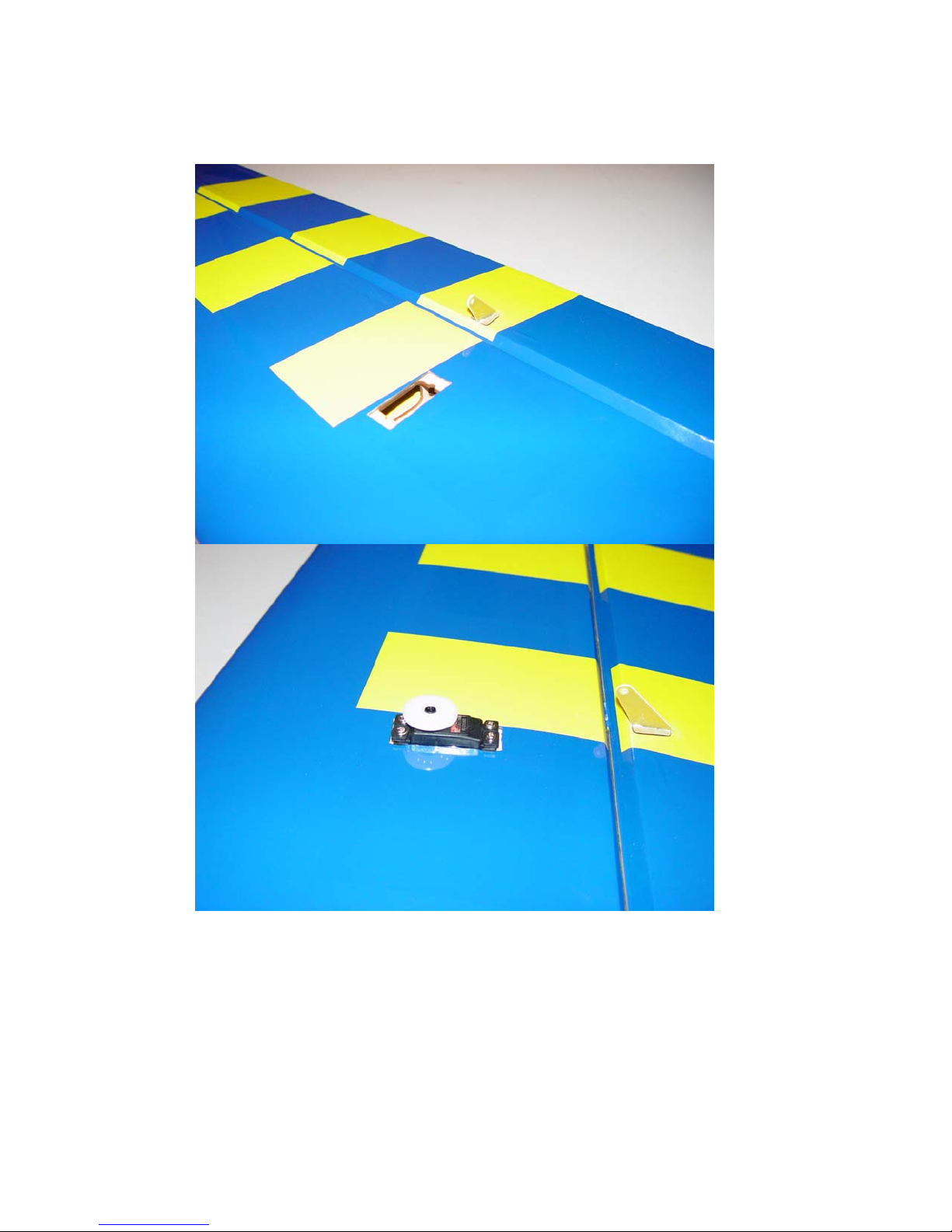
6. Remove the covering from the aileron servo bay and install the servo using the
manufacturer supplied servo mounting hardware. Position the servo as shown in
the picture. You will need to attach a 6 inch servo extension to the aileron servo.
7
Page 8
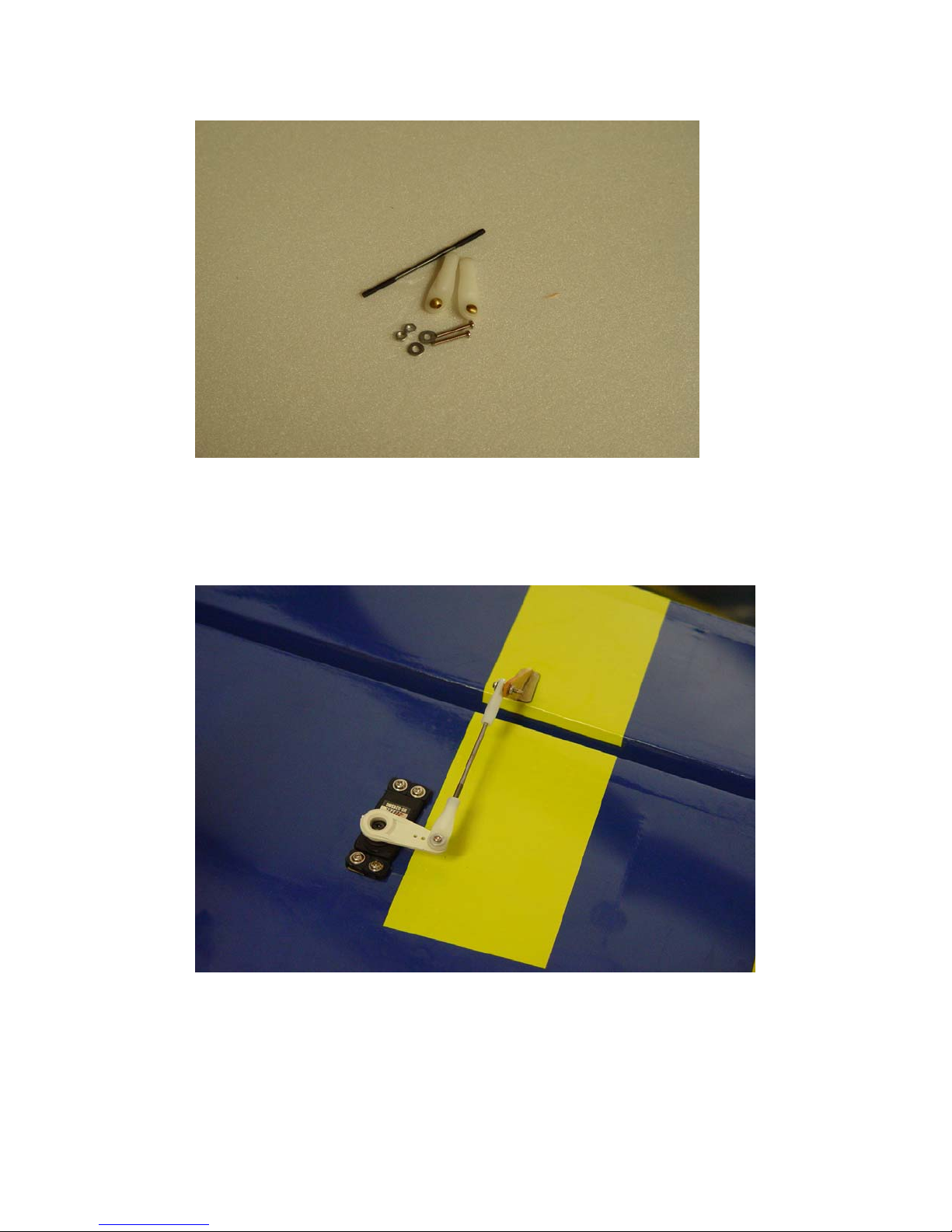
7. Locate the threaded aileron pushrods, 2 ball links, 2 screws, 2 nuts and 2 washers
that make up the aileron linkage.
8. We highly recommend the use of the Dubro heavy duty control arm set for the
Extra, Dubro part number 670 for Futaba, 671 for JR, and 672 for Hitec. For the
aileron linkage we will use the 1.14” (28.9mm) arm. Electronically center the
servo arm. Thread the ball links onto each end of the pushrod. Attach the
pushrod to the servo arm and control horn using the supplied screws, nuts and
washers as shown in the photo.
9. Repeat this process for the other wing and the wings are finished and ready for
flight!
Fuselage Assembly
10. Let’s mount the landing gear first. Locate the 2 carbon fiber landing gear legs, 4
3mm mounting bolts and washers, 2 main wheels, 2 axles and retaining nuts, 2
wheel collars, 2 wheel pants, 2 landing gear fairings and the 2 plywood mounting
plates.
8
Page 9
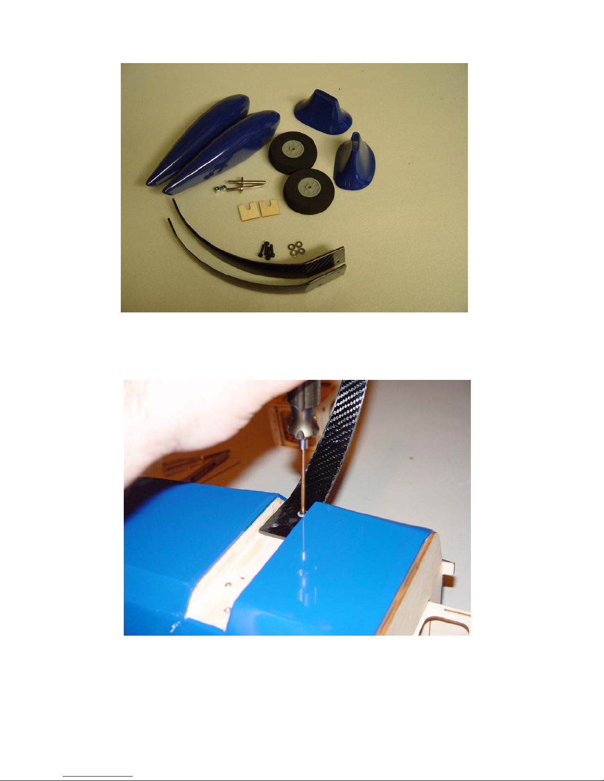
11. Before mounting the land ing gear, take a minute to wick thin CA into all
joints of the landing gear mounting area, both internal and external. Slide the 2
main landing gear legs into position from the side under the retaining lip. Secure the
legs with the 4 3mm bolts, using a washer on each bolt. Be sure to use a drop or two
of blue Loctite on each bolt.
12. Slide the landing gear fairings onto the gear and affix to the fuselage with silicon
glue or rubberized CA. You may need to open the slot in the fairing slightly for
correct fit.
9
Page 10
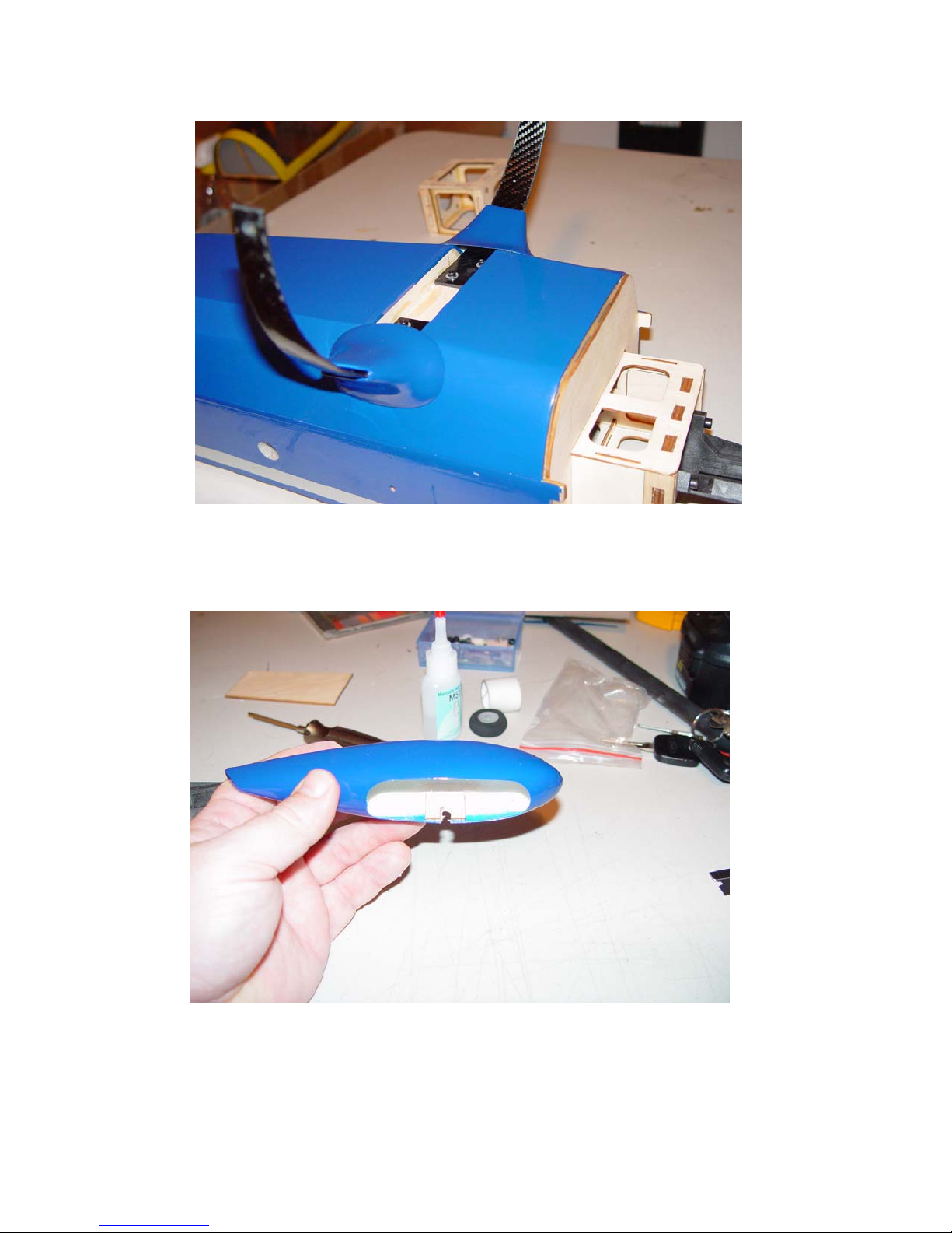
13. Glue the plywood mounting plate in the center of the wheel pant opening with 30
minute epoxy. Scuff the inside of the wheel pant with sandpaper before gluing.
Once dry use a rotary tool to open a slot in the wheel pant using the slot in the ply
plate as a guide. It should be big enough to slide over the threaded portion of the
axle.
14. Place the wheel on the axle followed by the wheel collar. Slide the wheel pant
over the axle with the retention ring inside the wheel pant. This ring will keep the
wheel pant in place with friction. Insert the threaded portion of the axle into the
hole in the end of the landing gear leg and secure with the nylon insert lock.
Please see picture for detail.
10
Page 11
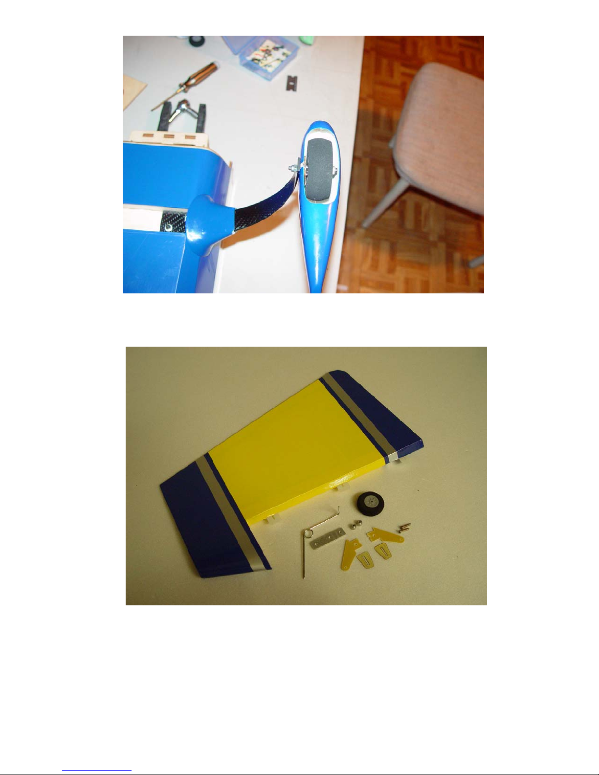
15. Next let’s mount the tailwheel and rudder so we can get the Extra up on its feet,
which will make the remainder of assembly much easier. Locate the rudder, 2
cut-down rudder horns and bases, tailwheel wire, aluminum mount, 2 coarse
threaded wood screws, tailwheel and 2 small wheel collars.
16. Locate the slot near the bottom of the rudder and remove the covering over it on
both sides of the rudder. Trial fit the horns into their base and into the slots. You
may need to remove a little more material from the horns so that they sit flush
against the base and rudder surface. Follow the same procedure as with the
aileron horn and remove the covering from under the base plate location for direct
adhesion to the wood. When satisfied with the fit, glue both horns in place with
30 minute epoxy. Be sure to scuff the horns with sandpaper for best adhesion.
Also be sure both horns are aligned properly and set assembly aside to dry.
11
Page 12
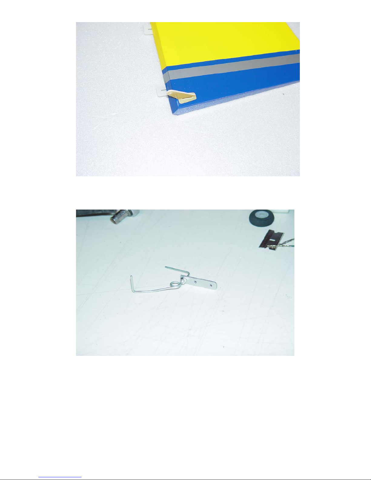
17. Slide one of the small wheel collars onto the landing gear wire and insert the wire
into the aluminum mount. Use a pair of pliers to make a 90 degree bend in the
wire as shown. Make sure to bend the wire so it is aligned with the
rudder/fuselage. Wait to tighten the collar set screw until a later step.
18. Drill a hole in the bottom portion of the rudder bevel to accept the tail gear wire
and cut a slot from the hole to the bottom of the rudder to conceal the vertical
portion of the wire. Glue the tailwheel assembly into the rudder with 30 minute
epoxy. Be sure to coat the interior of the hole well with epoxy. You may want to
add a piece of strapping tape over the wire for added strength. Place the tailwheel
into position and retain with the remaining small wheel collar.
12
Page 13
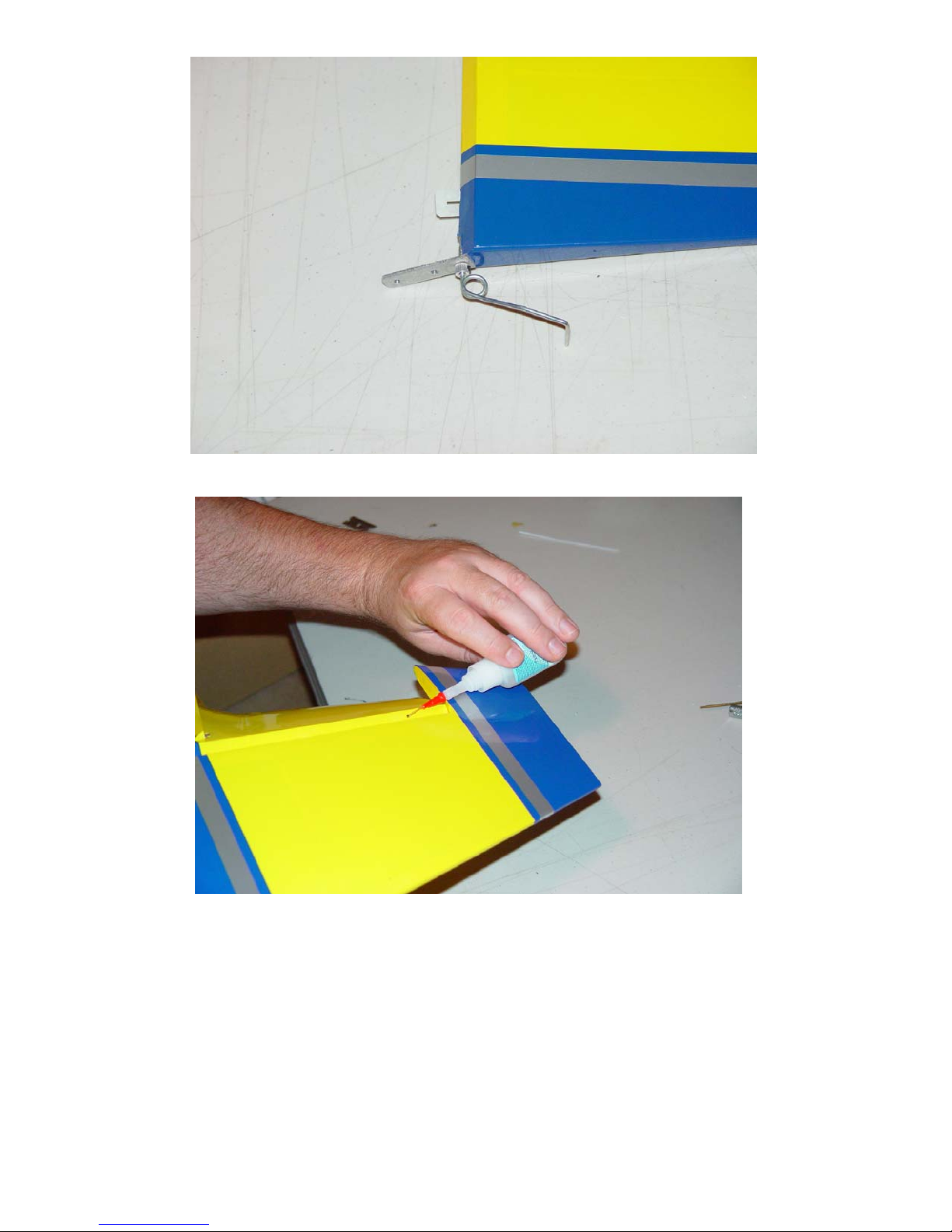
19. Slide the rudder into position on the rear of the fuselage and use thin CA to secure
the rudder hinges.
20. Align the aluminum mounting plate on the rear of the fuselage and secure with the
2 coarse threaded wood screws. You may want to wick a couple drops of CA into
the mounting holes before final installation of the screws. Tighten the setscrew in
the collar now.
13
Page 14
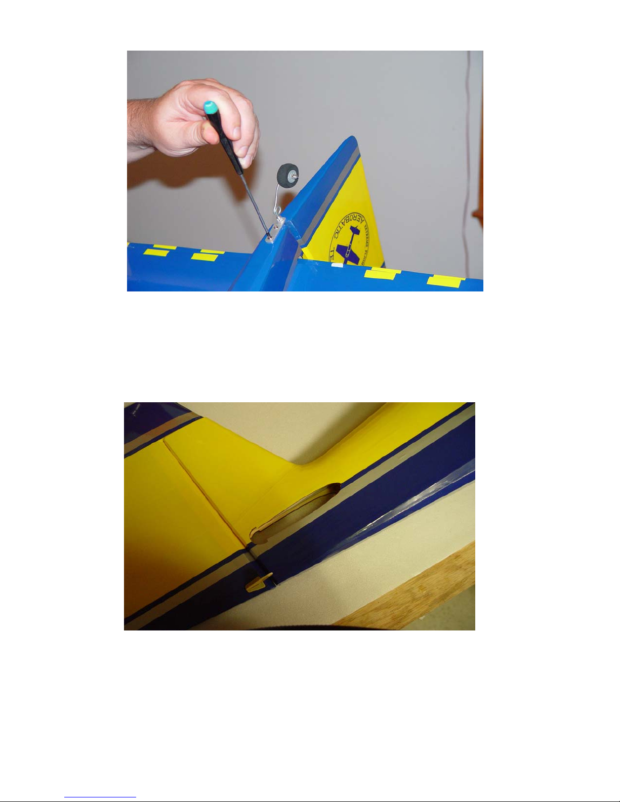
21. Next let’s install the horizontal stabilizer and elevator. Use a sharp hobby knife to
remove the covering from the openings in the side of the fuselage to accept the
horizontal stab and wing tube. Slide the carbon fiber wing tube into the fiberglass
socket in the fuselage and slide the wings into position. Insert the horizontal stab
into its slot and check to be sure the stab is aligned with the wings. Sand or shim
the slot for proper alignment. When satisfied with the alignment install the
horizontal stab using 30 minute epoxy. Proper stab alignment is crucial for best
flight performance so make sure to take your time here and get it right!
14
Page 15
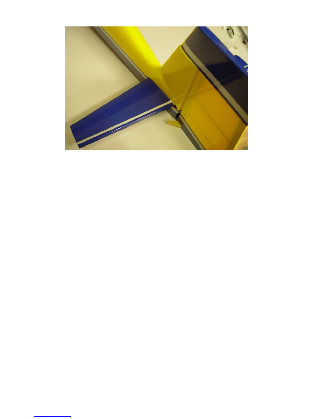
22. Now is the time to make your decision about using one or two servos for elevator
actuation. Our suggestion is to use a single HS-5245MG digital servo. If
converting the Extra to glow power it is probably wise to use 2 servos to counter
the additional weight of the glow engine. The elevator uses a hardwood joiner to
connect the elevator halves. This joiner is already glued into one half of the
elevator. If using a single servo, remove the covering from the hardwood joiner
where it will attach to the other elevator half for best adhesion. Place the elevator
side with the hardwood joiner already attached into position and insert the hinges
into their slots, but do not glue them into place yet. Apply 30 minute epoxy to the
bare wood of the other elevator half and to the hardwood joiner where you have
removed the covering. Place the 2nd elevator half into position inserting the
hinges into their slots, again, not gluing them into place at this time. Use masking
tape to align the counter balances to the stab and to secure the hardwood joiner to
the elevator until it dries. Wipe away any excess epoxy and allow assembly to
dry. Once dry, secure the CA hinges with thin CA. Please see picture on
following page for more detail.
15
Page 16
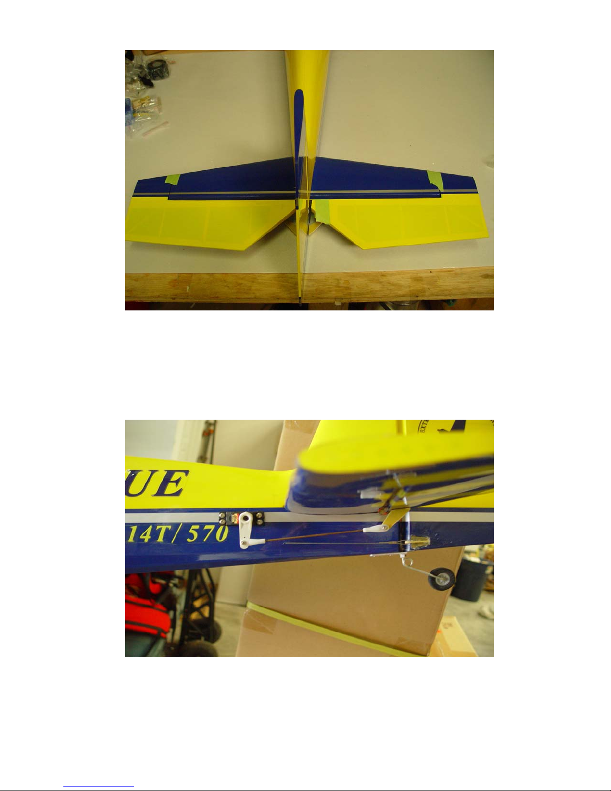
23. Using the same procedure as with the aileron and rudder, install the elevator
control horn and base in the bottom of the elevator with 30 minute epoxy. You
may need to trim the elevator horn slightly so it doesn’t protrude through the top
surface. Remove the covering from the servo slot in the rear of the fuselage and
install the elevator servo using the manufacturer supplied mounting hardware.
You will need an 18”-24” extension to reach the radio compartment. The linkage
assembles and installs just like the aileron linkage. We recommend the 1.375”
(34.9mm) Dubro arm for the elevator linkage. See picture for completed linkage.
24. If using 2 elevator servos, use a razor saw to cut the hardwood elevator joiner
flush with the edge of the elevator and glue this piece to the other side of the
elevator to make the beveled portion complete. Then cut this piece flush with the
side of the elevator. Use the same procedure as outlined above to install the 2nd
servo, horn and linkage. You will need to join these two servos via a mix in your
radio or with a reversing Y-harness.
16
Page 17
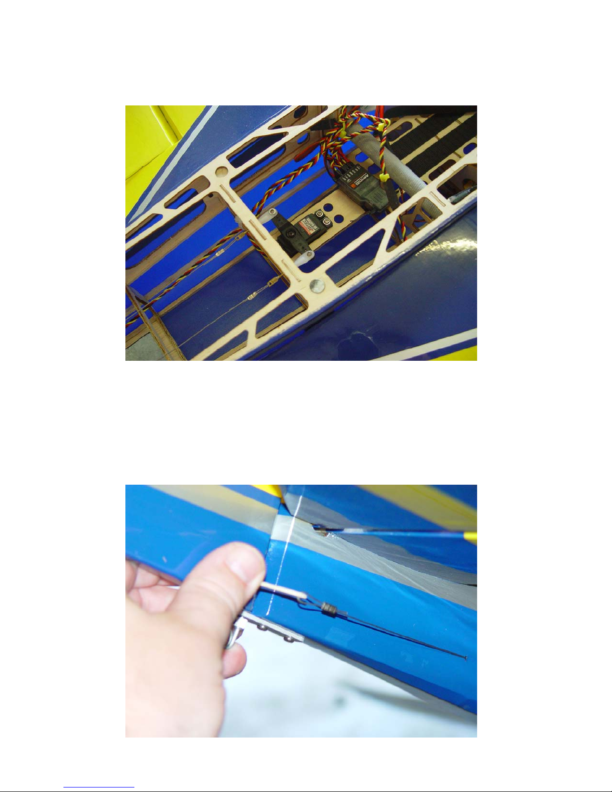
25. Next we’ll install the rudder servo and pull-pull system. Use the manufacturer
supplied hardware to mount the rudder servo in the tray as shown. Use either the
double arm supplied with the servo or the double arm that is part of the Dubro set.
26. There is a tube on each side of the fuselage just ahead of the rudder horn for the
pull-pull cables to pass through. Locate these holes and pierce with the end of the
cable. Insert the cable and push it through to the radio compartment, making sure
it doesn’t wrap around any of the formers.
27. I prefer to attach the cable at the rudder horn end first. Use a piece of masking
tape to secure the rudder counter balance to the vertical fin. Slide one of the
crimps onto the end of the cable and insert the cable through the hole in the rudder
control horn and back through the crimp. Use a pair of side cutters to crimp the
tube over the cable.
17
Page 18
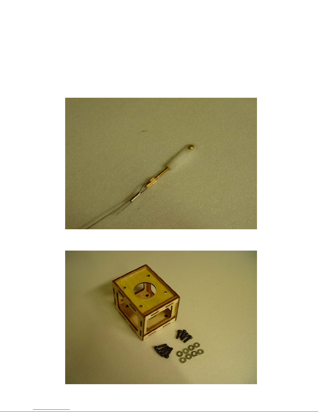
28. Locate one of the brass pull-pull connectors, a ball link, screw, washer and nut.
Thread the ball link onto the brass connector. Slide the crimp onto the cable,
insert the cable through the hole in the brass connector and back through the
crimp. Make sure the length of the cable is correct (small adjustments can be
made by screwing the ball link in or out on the brass connector) and crimp the
tube with side cutters. Attach the ball link to the servo arm using the supplied
screw, washer and nut. Repeat for the other side and adjust cables so they are
taut, but not overly tight.
29. Now let’s mount the motor. Locate the motor box, 8 mounting bolts and 8
washers. Using 4 washers and the 4 shortest bolts mount the motor box to the
front of the fuselage. Be sure to use a drop of Loctite on each bolt.
18
Page 19
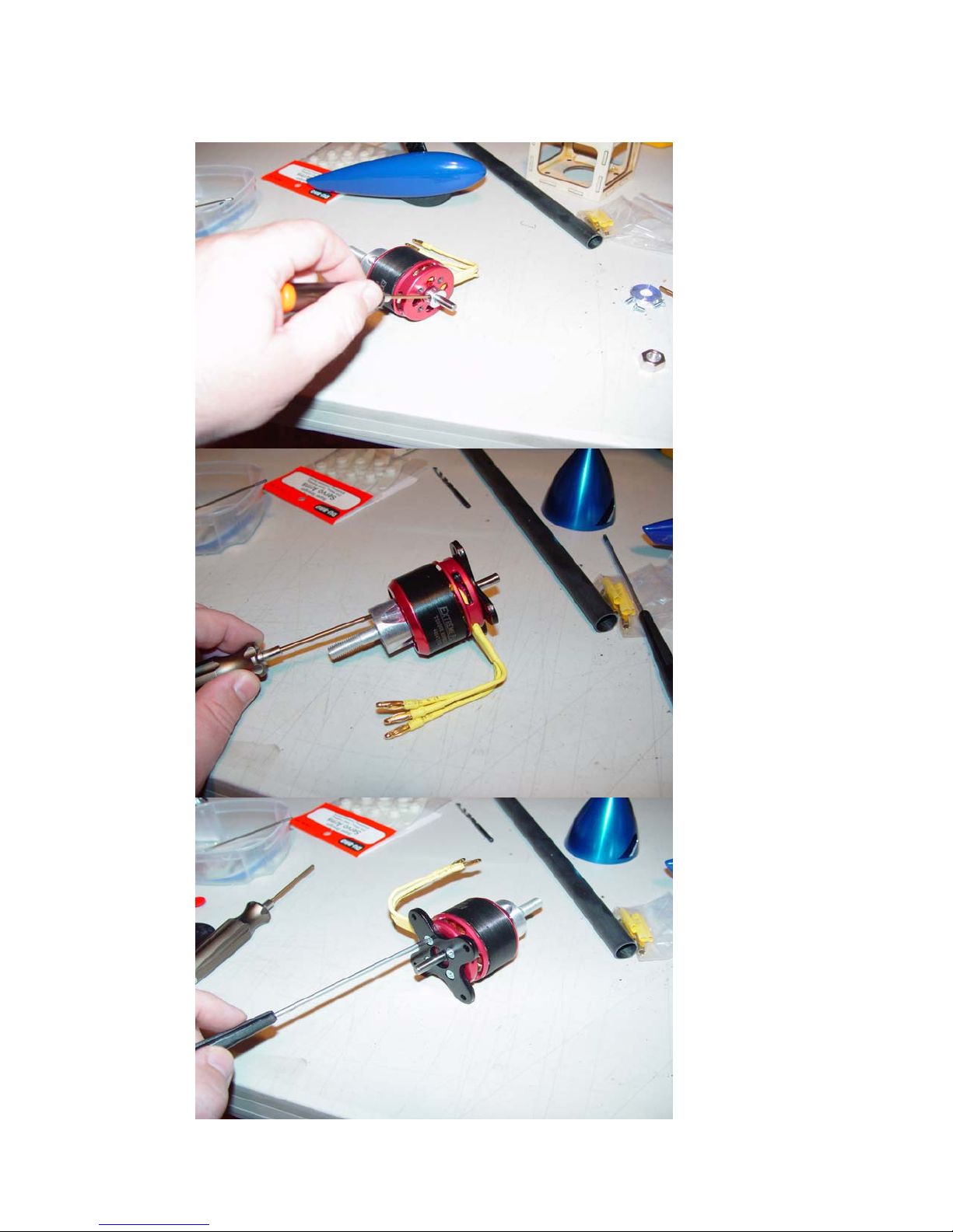
30. Prepare the motor for mounting. First slide the retaining collar onto the shaft and
tighten the set screw. Next mount the bolt-on prop adapter using the 4 long
screws included with the Torque Motor. Finally install the radial mount using the
4 beveled head screws.
19
Page 20
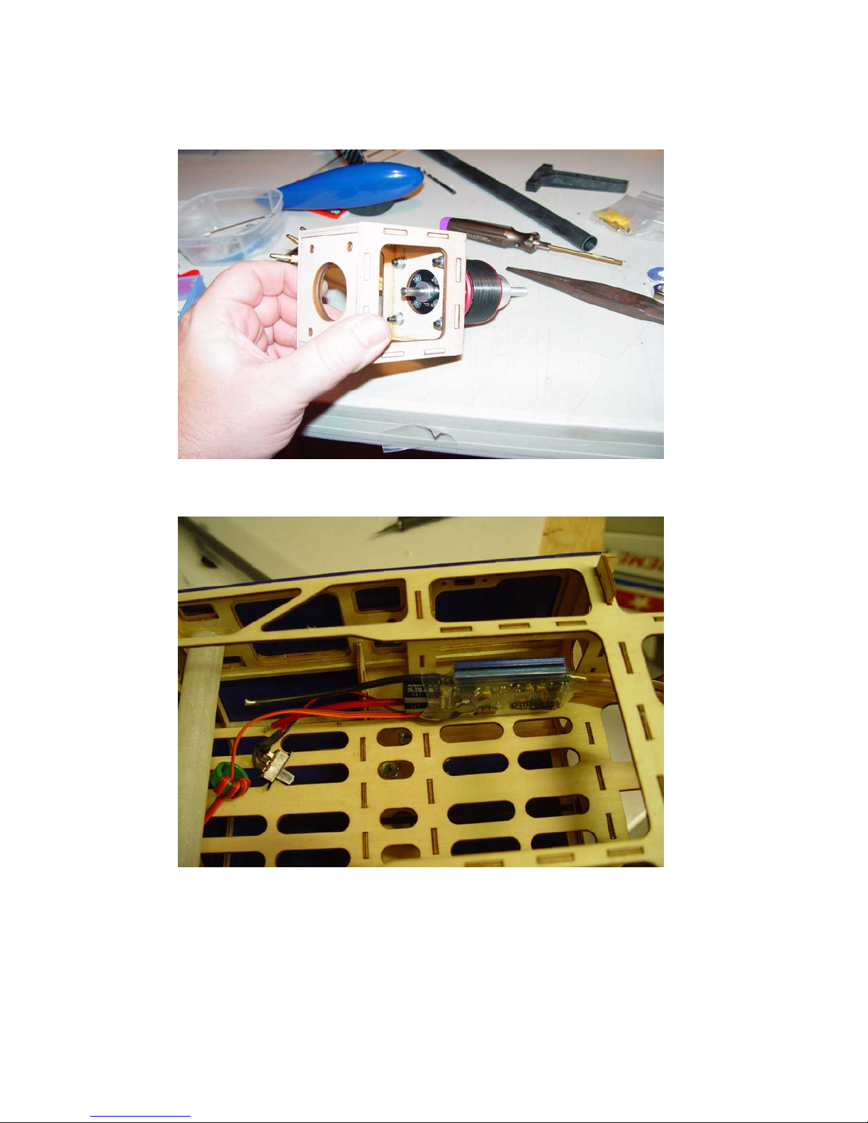
31. Next mount the motor to the front of the motor box using the remaining 4 bolts,
washers and lock nuts. In the photos the motor is mounted before installing the
motor box, but this is only for a better view of the mounting procedure. I have
found it much easier to mount the motor box to the fuselage first, as outlined
previously.
32. Mount the ESC in the position shown. You may want to add a scrap piece of
balsa or lite ply here to facilitate mounting of the ESC. Use Velcro or cable ties
to secure the ESC.
33. Solder your choice of battery connector to the ESC (probably easier to do before
mounting it). We prefer the Deans style connector. Attach the motor to the ESC
via the 3 bullet connectors in any order. Upon powering up the system, if the
motor runs in the wrong direction, switch any two wires and the motor will run in
the proper direction. Always test this without a propeller to prevent injury.
34. Now let’s mount the cowl. First, wick some thin CA into the cowl mounting
tabs. Place 2 pieces of masking tape on the fuselage and mounting tabs as
shown. Use a pen to mark the center of the mounting tabs on the tape.
20
Page 21
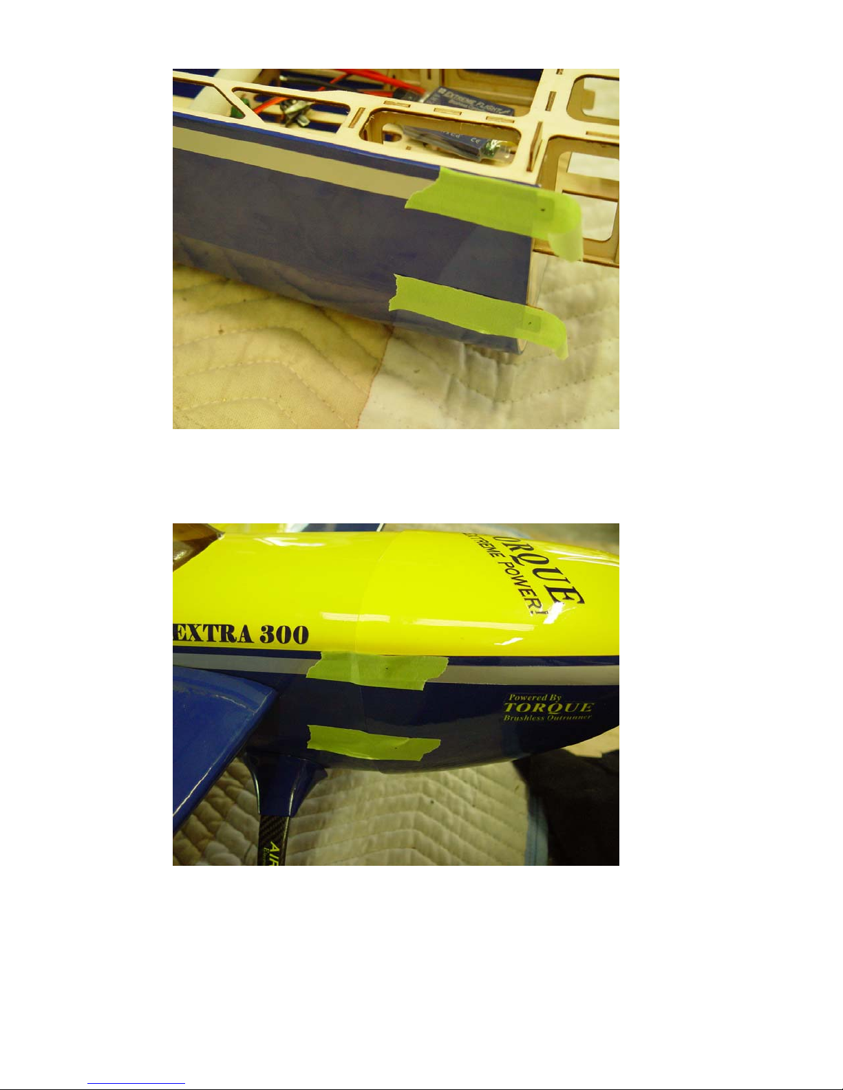
35. Place the canopy/hatch into position and secure with the spring loaded hatch
latch. Peel the masking tape back far enough to place the cowl into position.
Mount the spinner to the motor to aid in alignment. View the cowl from several
perspectives to insure proper alignment and once satisfied lay the tape back into
position on the cowl.
36. Use a small drill bit to make a hole at the proper location and secure the cowl with
4 of the small wood screws. Install prop and spinner.
21
Page 22
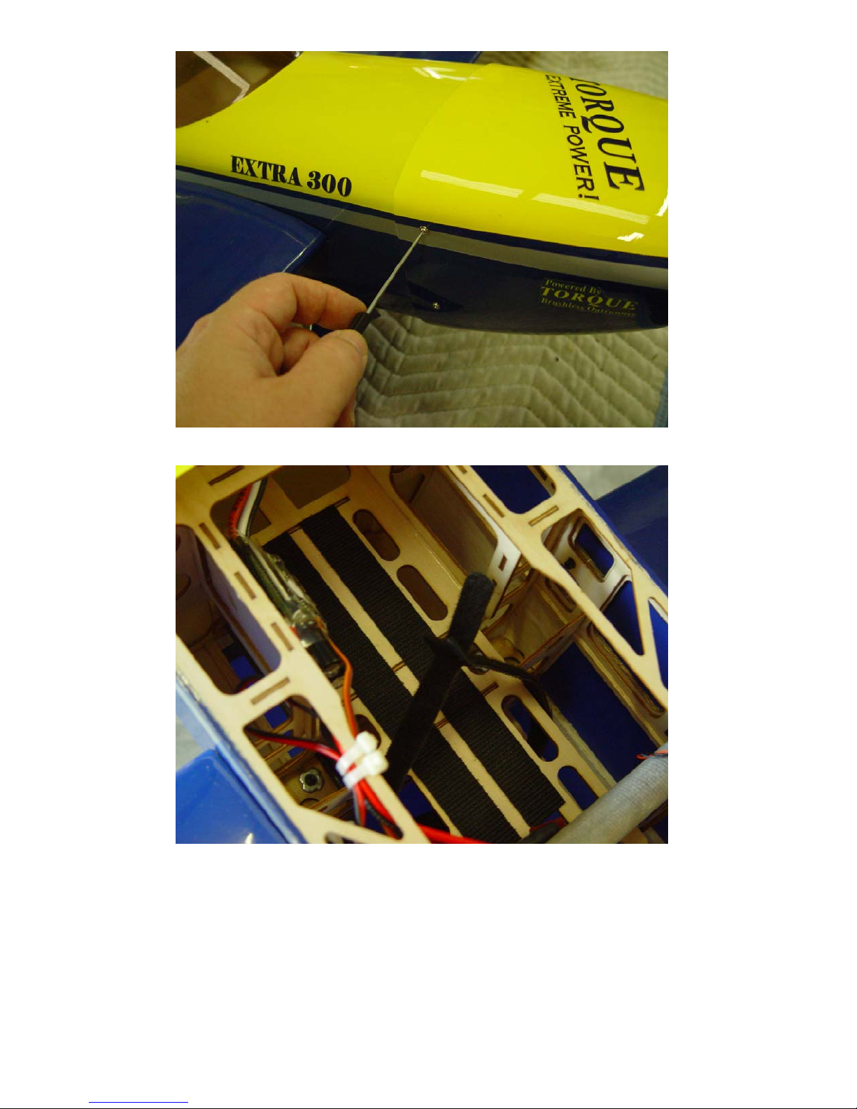
37. Apply Velcro to the battery tray as shown (not included) and use a Velcro strap to
secure the battery.
38. Below is a picture of our complete radio installation inside the Extra for your
reference.
22
Page 23
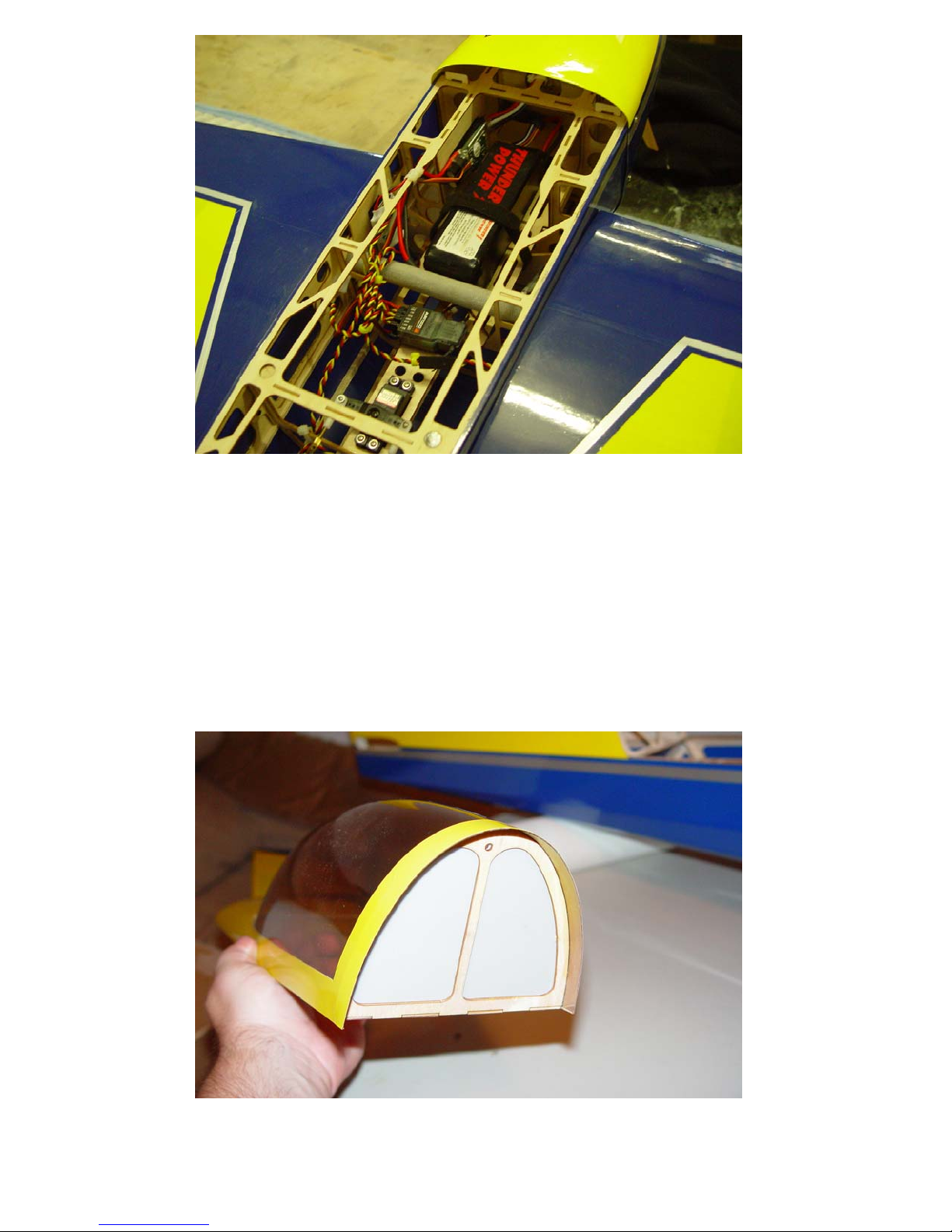
39. Insert the carbon fiber wing tube into the fiberglass socket and slide the wings
into position and secure with the nylon thumb screws. The screw is inserted from
inside the fuselage and into the blind nut in the wing root. Connect the aileron
servo leads to the receiver. You may want to install 2 short servo leads into the
aileron and auxiliary ports on the receiver to make plugging in the aileron servos
easier. Alternately you can use a Y-harness for the aileron servos.
Cockpit Assembly
40. Your Extra includes one of our new “PILOT X” helmet head pilot bust figures
and a detailed dash panel, as well as a Depron cockpit floor. Installation of these
components only requires a few minutes and adds a nice scale touch to the Extra.
Locate the Depron floor and rear canopy insert, pilot bust figure and dash panel.
Use foam safe CA or aliphatic resin (white glue) to secure the rear canopy insert.
You may need to lightly sand the edges for a perfect fit.
23
Page 24
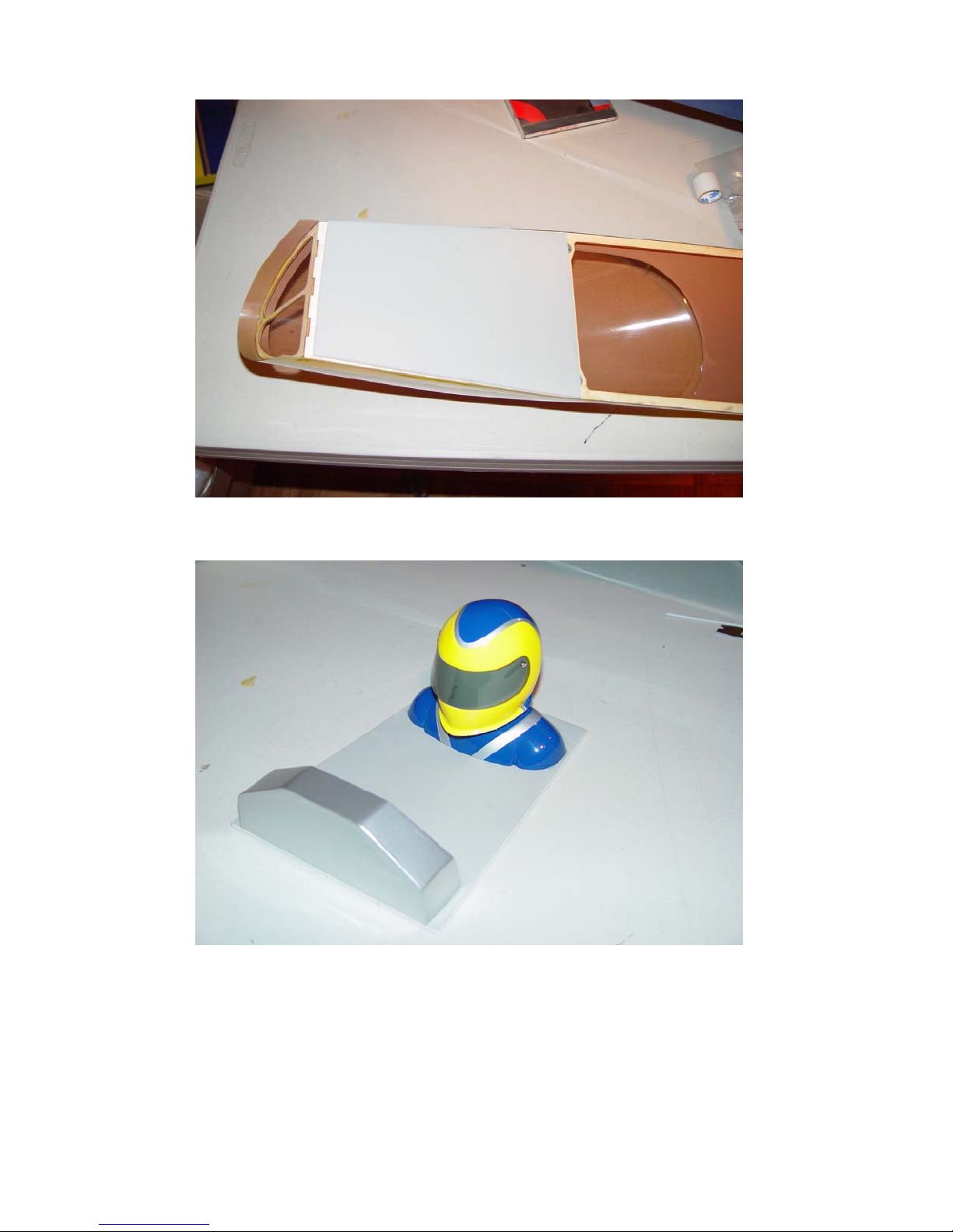
41. Hold the Depron canopy floor up to the bottom of the canopy/hatch and mark the
location of the center of the cross member onto the Depron. Cut the floor into 2
pieces at this location.
42. Use foam safe CA to secure the pilot and dash panel into position as shown. The
dash panel should overhang the Depron floor by 1/8” to hide the seam of the 2
floor pieces.
43. Slide the pilot/dash floor assembly into position through the portion of the canopy
in front of the cross member. It may take a little effort, but is quite doable.
Secure with foam safe CA. Slide the remaining piece of Depron floor into
position and secure with foam safe CA. You may find installation easier if you
cut off the front 3 or 4 inches of the Depron floor. This will be hidden under the
canopy. See picture for detail.
24
Page 25
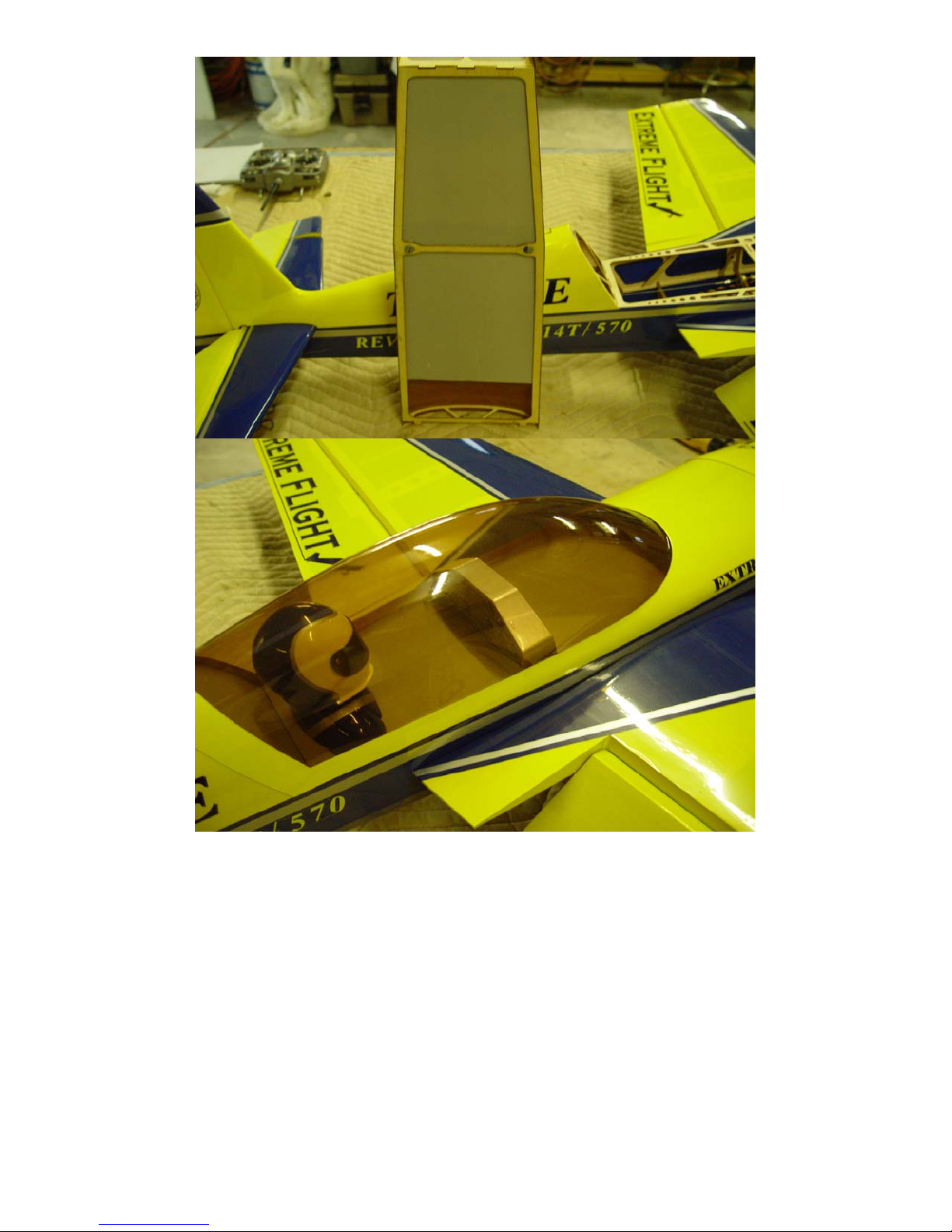
This concludes the assembly of your Extra!
25
Page 26

Set-up and flight tips.
CG range for the Extra is from the front of the wing tube to the back of the wing tube.
Use the wing tube socket in the wing root to determine the location and transfer this
position to the bottom of the wing using a felt tipped marker. CG is determined with
the Extra in the upright position. Correct CG should be easy to achieve by moving
the battery along the length of the battery tray. Adjust to fit your flying style. One of
the best ways to dial in the proper CG for your aircraft is the 45 degree line test. Fly
the aircraft in front of you from left to right (or right to left if you prefer) at ¾ throttle.
Pull the aircraft into a 45 degree up line and establish this line. Roll the aircraft
inverted, neutralize the elevator and pay close attention to what the plane does.
Ideally the plane will continue on this line for several hundred feet before it starts to
slowly level off. If the airplane immediately drops the nose it is nose heavy. If it
begins to climb inverted toward the gear it is tail heavy. Adjust the battery position
until you determine the proper CG and mark the battery tray so you can place the
battery accurately each flight.
Control surface recommendations are as follows:
Elevator- 10 degrees low rates, 45+ degrees high rates.
Rudder- 20 degrees low rates, 45+ degrees high rates.
Aileron- 15 degrees low rates, 35+ degrees high rates.
Use exponential function to achieve the best “feel” for your particular flying style. I
highly recommend that you take the time to set up rates for precision flying and
separate rates for 3D. The Extra is capable of flying very precise maneuvers, and
proper rates and CG will allow you to experience this to the fullest extent. Trying to
fly precision aerobatics with 3D rates is an exercise in futility. Spend some time
dialing in and trimming your plane and you will be rewarded with a great flying
experience.
Thanks again for your business!
See you at the flying field!
26
 Loading...