

Page 1
Page 2

Please read the following paragraphs before beginning assembly of your aircraft!
THIS IS NOT A TOY! Serious injury, destruction of property, or even death may result from the misuse of this
product. Extreme Flight RC is providing you, the consumer with a very high quality model aircraft component kit, from which you, the consumer, will assemble a flying model. It is beyond our control to monitor the
finished aircraft you produce. Extreme Flight RC will in no way accept or assume responsibility or liability
for damages resulting from the use of this user assembled product. This aircraft should be flown in accordance to the AMA safety code (or code appropirate to your region). It is highly recommended that you
join the Academy of Model Aeronautics in order to be properly insured, and to operate your model at AMA
sanctioned flying fields only. If you are not willing to accept ALL liability for the use of this product, please
return it to the place of purchase immediately.
Extreme Flight RC guarantees this kit to be free of defects in materials and workmanship for a period of 30
DAYS from the date of purchase. All warranty claims must be accompanied by the original dated receipt.
This warranty is extended to the original purchaser of the aircraft kit only.
Extreme Flight RC in no way warranties its aircraft against flutter. We have put these aircraft through the
most grueling flight tests imaginable and have not experienced any control surface flutter. Proper servo selection and linkage set-up is absolutely essential. Inadequate servos or improper linkage set up may result
in flutter and possibly the complete destruction of your aircraft. If you are not experienced in this type of
linkage set-up or have questions regarding servo choices, please contact us at info@extremeflightrc.com or
770-887-1794. It is your responsibility to ensure the airworthiness of your model.
Special notes on the 104” Extra 260 aircraft::
1.The 104” Extra 260 aircraft is shipped to you with Pre-hinged control surfaces with gap-seals already
installed.
2.The 104” Extra 260 aircraft is shipped to you with control horns already installed.
3.The 104” Extra 260 does not use SFGs, however it has 3mm threaded holes in the wingtips for the attachment of night flying lights.
4.The 104” Extra 260 has an extremely wide Center-of-Gravity range. If you are using a twin-cylinder gasoline engine 120-123CC, it is not necessary to check the CG before flight.
5.Our test aircraft used GP123cc and DA120cc engines with 28x10 carbon props. Our test aircraft used
SAVOX 2290SG servos.
6.The 104” Extra 260 uses one rear-mounted push-pull rudder servo location for strength and simplicity.
There are mounting locations forward for pull-pull cable installation of rudder servo(s), we do not recommend them for any typical installation.
Page 3
Your aircra has been on a journey around the world since it le our factory. Although the covering material
was perfectly smooth when it was boxed up, changes in weather and humidity may have wrinkled the covering
material. For certain, wrinkles will appear in the covering once you have unpacked your aircra and it adjusts
to the atmospheric conditions in your region. Learning to remove wrinkles from covering is a necessary skill to
maintain your wood aircra.
Your Extreme-Flight produced aircra is covered in Ultracote covering material (US market name), also called
Oracover in global markets. If you need replacement covering to repair damage, Ultracote/Oracover is widely
available from retail hobby suppliers. Also, each roll of Ultracote/Oracover includes excellent instructions which
are also available online. Please refer to them for details about working with and/or repairing your covering.
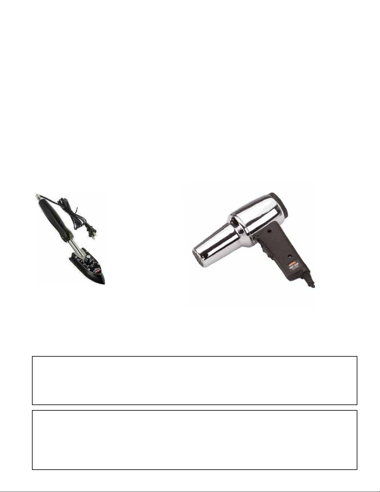
e basic tools are a covering iron and a hobby heat gun. Start by using the iron at 220F (104C) to seal all of the
edges on the covering scheme. is is CRITICAL on the leading edges of wings and stabilizers. en use the
iron at 300F (149C) or a heat gun to shrink out any wrinkles in the covering. Remove the plastic canopy from
the aircra when using a heat gun to protect it from heat damage. GO SLOWLY AND CAREFULLY to avoid
over-shrinking or burning the covering. is is a skill which takes a bit of practice. ere are many tutorial videos online demonstrating shrinking wrinkles from Ultracote. e most common mistake is over-shrinking on a
seam between colors, causing straight color lines to become skewed.
Periodically repeat the sealing and shrinking process to keep your aircra in good condition.
e cowling, canopy and wheel pants on your Extra 260 are painted in automotive enamel paint. Standard car
wax and detailing products work well to maintain them. If you need to repair the paint, we recommend a basic
enamel spray paint. Below are the RAL codes which are a close match for those Ultracote colors which can be
matched.
In the USA, LVPpaints.com currently oers aordable spray cans matched to RAL codes.
Oracover colors Ultracote colors RAL color
Blue/Orange Scheme
Dark Blue #52 Midnight Blue- # HANU885 RAL5013
Orange #60 Orange - #HAN877 RAL2004
White #10 White-# HANU870 RAL9010
White/Blue/Red scheme
Dark Blue #52 Midnight Blue- # HANU885 RAL5013
White #10 White-# HANU870 RAL9010
Ferrari Red #23 True Red #HANU 866 RAL3000
Silver #91 Silver-#HANU881 N/A
Page 4
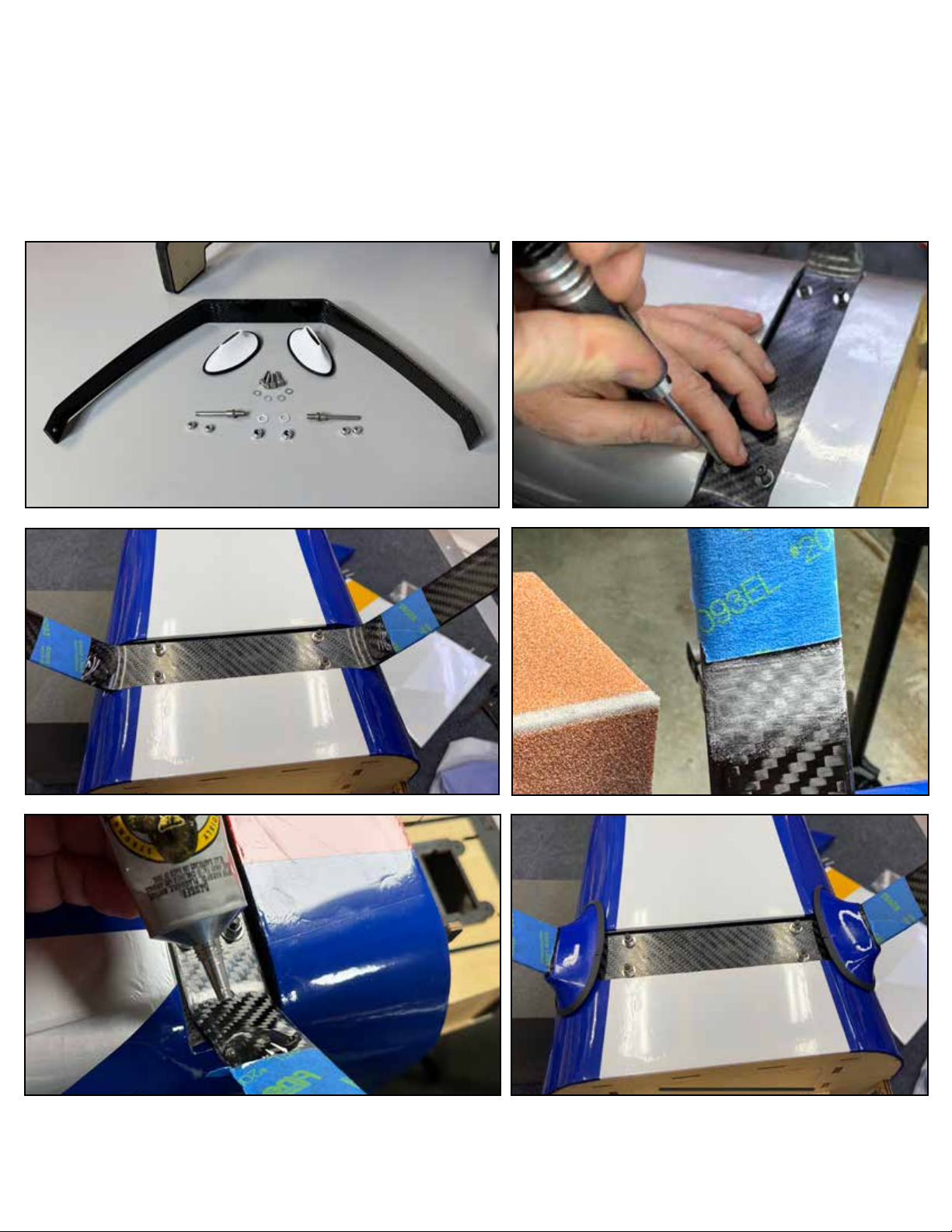
Bolt the landing gear to the fuselage, the gear sweep slightly forward when installed correctly. Use
blue loctite or equivalent threadlocker on the gear attachment bolts. Locate the gear-to-fuselage
fairings. Test t the fairings and place a piece of masking tape at the top of fairings around the
landing gear legs. Lightly scu the gear legs just below tape with sandpaper or emery cloth.
We recommend to glue the fairings to the landing gear *only* (not to the fuselage) with a large
dollop of rubberized glue such as “Goop” or “Gorilla Clear Bond”. Tape the fairings in place until
the glue is dried.
Page 5
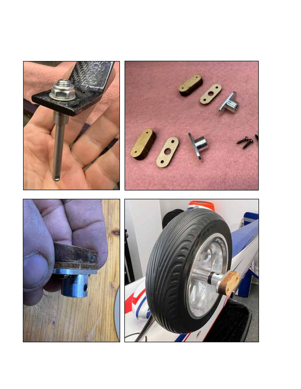
e axle system includes a wheel-pant-saver mechanism. Begin by attaching the axles to the
landing gear with washers and self-locking nuts, nd the at spot on the outboard end of the
axle and orient this at spot *down* to face the runway. Assemble the “pant saver” as shown
and install the wheels as shown with the pant saver as the outboard wheel retainer. Use blue
loctite on the set screw. In these photos, we show the installation of optional “Spot On” wheels,
available from Extreme Flight RC.
Page 6
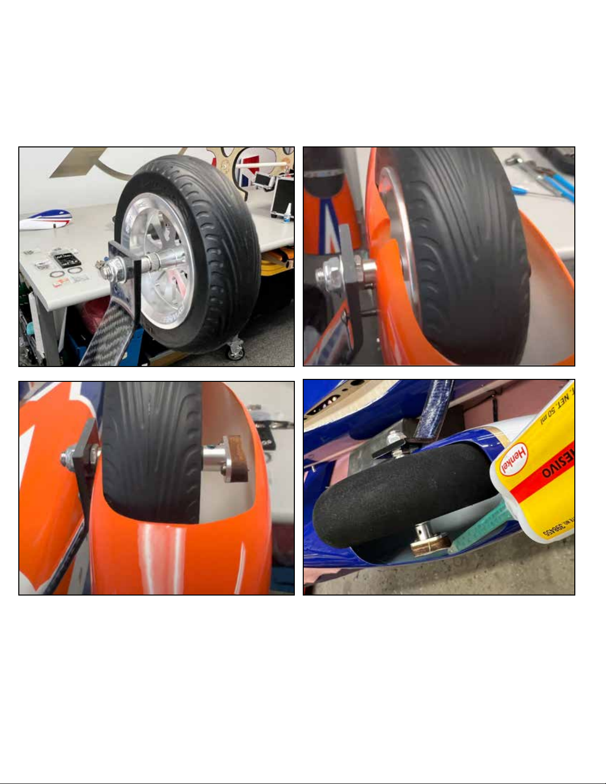
Aer applying blue loctite, start the bolts which hold the wheelpant into the landing gear, but
leave them loose. Please a dab of epoxy glue or rubberized glue such as “Gorilla Clear Bond”
between the wooden pad of the “pant saver” and the wheelpant. Tighten the bolts holding the
wheelpant to the landing gear.
Page 7
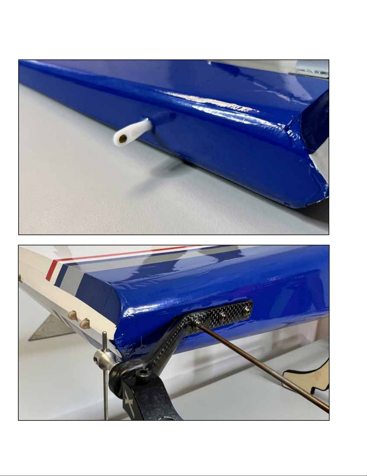
Locate the tailwheel, bolts, and tiller keeper (nylon ball link). Glue the keeper into the hole
in the bottom of the rudder with epoxy. Install the tailwheel onto the fuse using the bolts
and blue loctite threadlocker.
Page 8
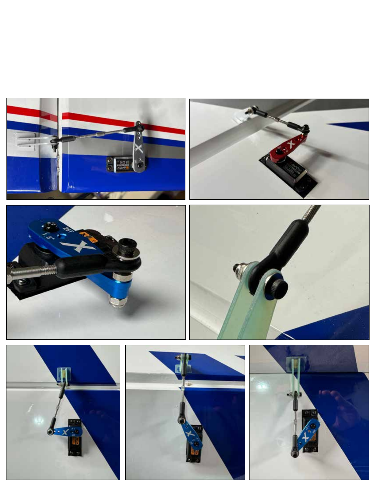
Install the rudder servo as shown. e Extra 260 has a tube installed in the fuselage to contain the
servo extensions runing to the tail, it is easiest to install all three extensions through it at once.
When installing servo screws, the best practice is to thread the screw in, remove it it, add a drop of
thin CA glue to the hole, and then replace the screw. Note that we were able to achieve full rudder
throw while using the 1.75” hole location on the 2” length arm.
Install the aileron servos in the same way. Note that we used the 1.5” location on the 1.5” length
arm. Also note that on the rudder and aileron installations, the linkage is “crooked” when the servo
is in the neutral position, and becomes “straight” when the servo is at full travel. is is by design,
to minimize the side-loading of the control horn at full deection/load.
Page 9
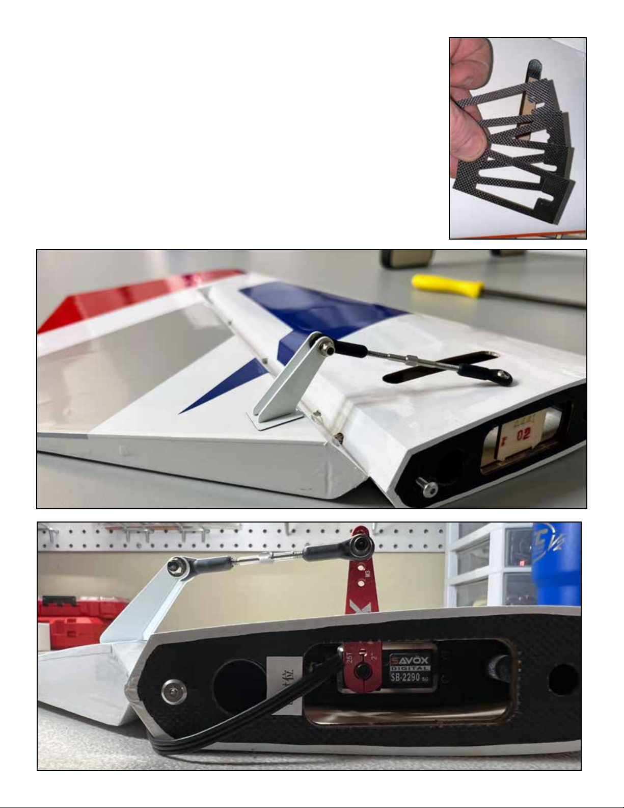
When you receive your kit, the elevator servo location will be
obstructed by a wooden ID tag. Snip this away and discard it.
Install the elevator servos as shown. Note that the location of the
slot in the sheeting, relative to the servo mount, is arranged for
most common servos with our Extreme Flight servo arms. Some
servo/arm combinations may rub the side of the slot. Your kit
includes spacers for the servo mount, use if needed to space the
servo in that direction, or trim the slot as needed.
Note that we were able to achieve full elevator deection using the
1.75” location on the 2” length servo arm.
Page 10
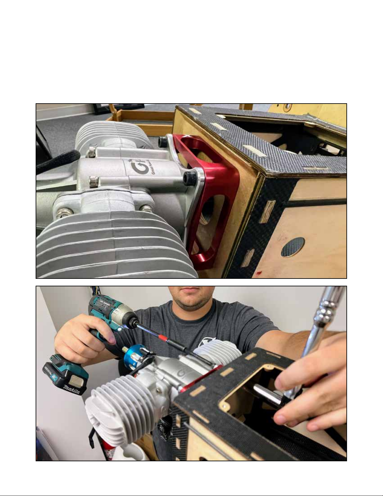
Drill the rewall as appropriate for your engine. e DA-120/GP-123 pattern is marked on the
rewall for you. Use large washers and locking nuts on your engine mounting bolts. For the DA120 and GP-123, you will need the Blazing Star DA-120 mount, available from Extreme Flight RC.
Note that these engines are slightly dierent in overall length, and berglass cowls can vary slightly in length. So, the Blazing star mount includes spacers so you can set the distance from your
spinner backplate to the cowl perfectly, and additional spacers are available from Extreme Flight
if needed. Place these spacers between the mount and the wood rewall. Note that we include
3 degrees of right thrust built into the rewall of the Extra 260, so the clearance of the prop and
spinner to the cowl will be dierent on the right and le sides.
Page 11
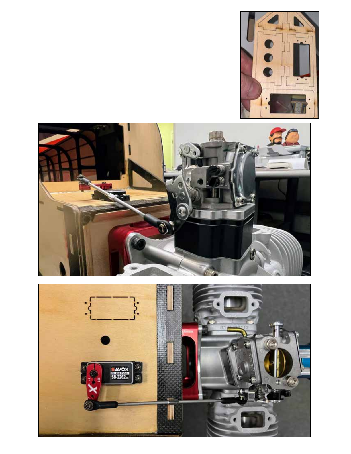
Pictured is a typical throttle servo installation. Take care to ensure
that the pushrod does not contact the motor box at any point in
its travel. Note there are two servo locations, as dierent brands of
engines have the throttle arm on opposite sides. Depending on your
exact setup, you may turn your servo around in the opposite direction to achieve the best t.
ere is a large air-vent hole in the lower front of the cowl on the
Extra 260, which makes choke access very easy. However, if you
desire to install a choke servo, we include a laser cut servo mount
which you can assemble and install in a convenient location.
Page 12
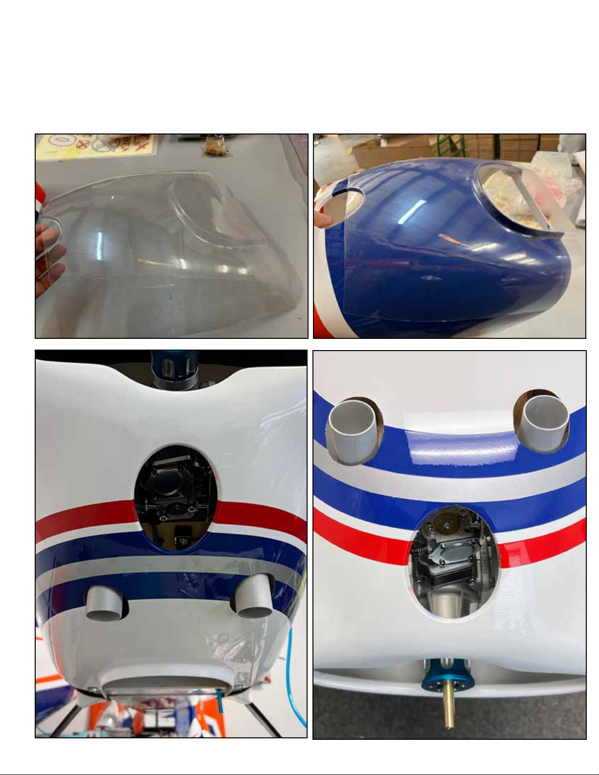
For stock muer exits, you will need to cut holes into the bottom of the cowling. To
make the job of locating these holes easier, your Extra 260 kit includes a clear plastic template the same shape as the bottom of the cowl. Tape this template to the fuselage, mark
and trial-cut the holes in the clear template. When satised with the t, transfer the hole
locations to the actual cowl and cut, using a dremel-type tool with a grinding stone/sanding drum. is creates berglass dust, so wear eye, skin, and lung protection.
Page 13
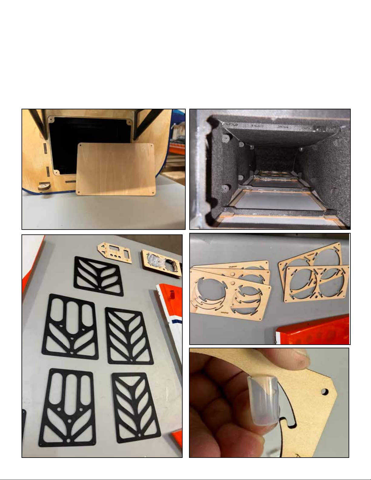
If using stock muers which exit through the cowl bottom, we recommend you install the cover
plate on the front of the fuselage exhaust tunnel as shown. e pre-fabricated air outlet on the
bottom of the cowl has proven more than adequate in hot-weather ying.
If using canister muers or tuned pipes, the exhaust tunnel has three vent openings which you
can open. We include vent plates for these openings with optional outlets in the rear plates for
cans or pipes. Remove the covering over these locations on the bottom of the fuselage and install
the plates with screws, using thin CA glue to harden the screw holes. Mounting plates for cans or
pipes are included, use the included silicone tube sections to cushion the mounts.
Page 14
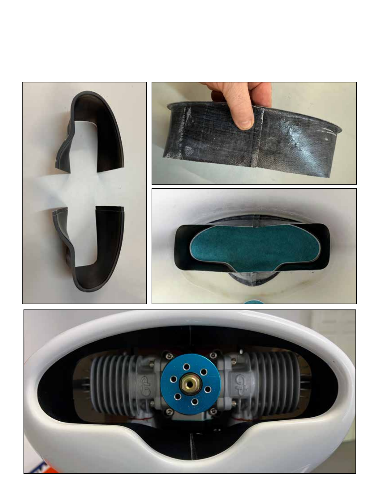
Your Extra 260 kit includes a two-piece berglass cooling duct (also called a “bae”). Because
some engines have their le cylinder forward, and some the right, the duct is uncut and you
will need to trim it to t your cylinders. e duct is easily cut with scissors or a dremel tool.
e duct should t close to the cylinder without quite touching, leave 3-4mm clearance. Glue
the duct into the cowl as shown with epoxy or rubberized glue.
Page 15
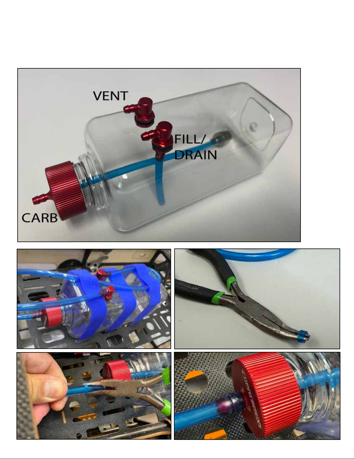
We recommend Extreme Flight Flowmaster tanks. Strap your tank securely to the tray with
multiple velcro straps and velcro between the tank and tray. Make a loop as shown in the vent
line to prevent fuel siphoning during ight. We use short sections of fuel line as “hose clamps”
on our fuel line connections.
Page 16
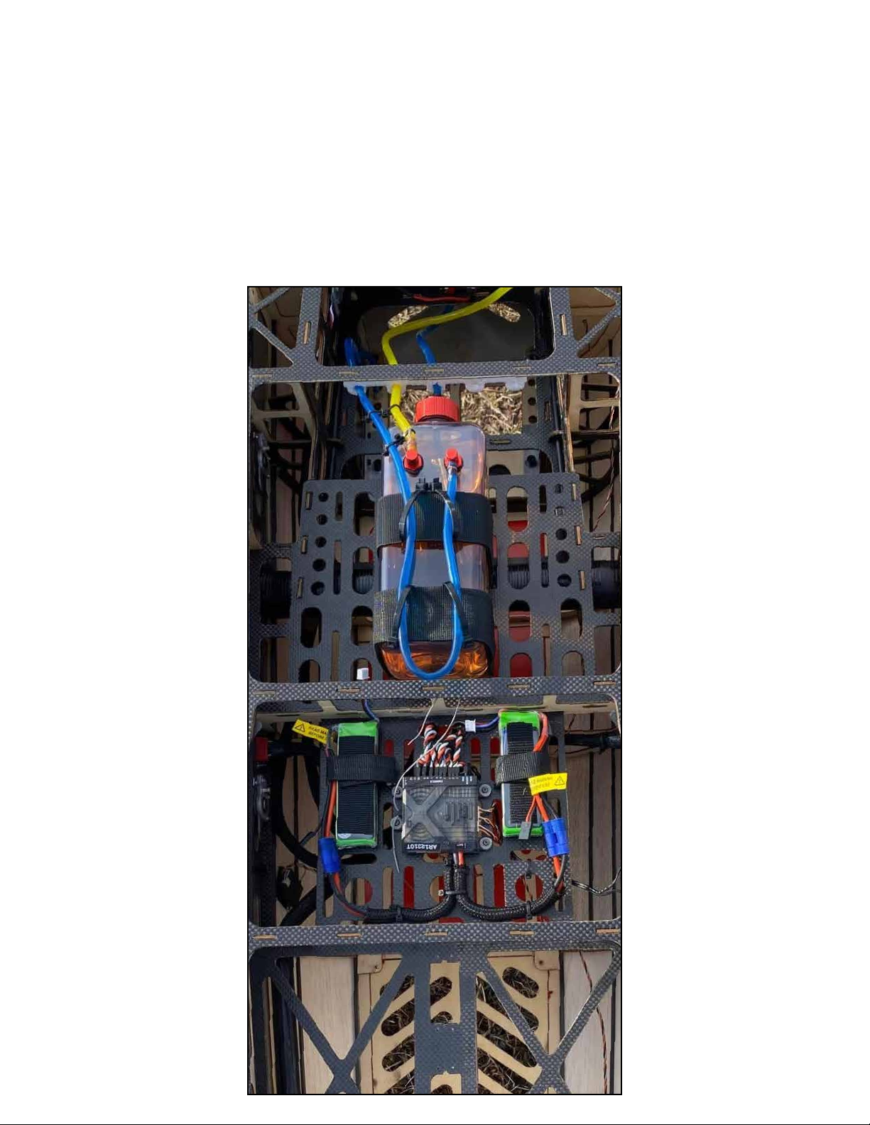
Here are typical equipment installation locations for this aircra. e CG location
our pilots like for aerobatic ight is just behind the wing tube, approximately the rear
edge of the tube to 1” behind the tube. Your favorite position may be quite dierent.
If you are using a 120-123CC twin gas engine, it is not necessary to check the CG
location of the aircra, it will fall in the acceptable range. Fly the aircra and adjust to
your liking.
When using stock muers, we prefer the receiver batteries alongside the receiver, or
alongside the tank. If a dierent CG is desired, there is a wide range of placement for
the batteries available to adjust.
Page 17
Recommended control settings are as follows:
Aileron Low: 20 deg up, 20 deg down 18-20% exponential
High: 38 deg up, 37 deg down 50-60% exponential
Elevator Low: 10-12 deg 18-20% exponential
High/3D: 45-50 deg 50-60% exponential
XA/Tumbling: 60+ deg 60-70% exponential
Rudder Low: 20 deg 50-60% exponential
High: 45+ deg 60-80% exponential
NOTE: This high rate aileron is an extreme setting and will result in a roll rate which
is quite fast and may, for some pilots, be dicult to “keep up with” until you get
used to it. If your transmitter has a mid rate for ailerons, set it to approx 32 degrees
and 50% expo and this may help you get acquainted with this very high-performance aircraft.
Likewise, note that the “3D” elevator setting is optimized for smooth 3D performance in harrier, the “XA/Tumbling” rate may make it dicult to be extremely
smooth down low until you are used to it.
If this is your rst aircraft with dual aileron servos, be sure to familiarize yourself
with the routine your transmitter uses for “balancing” servo travel on a dual-servo
installation.
We recommend only carbon-ber props for maximum performance on this aircraft. 27x11, 28x9.5 and 28x10 are our favorites for our typical ying sites under
2,500 ft altitude, with 28x10 being the Team favorite.
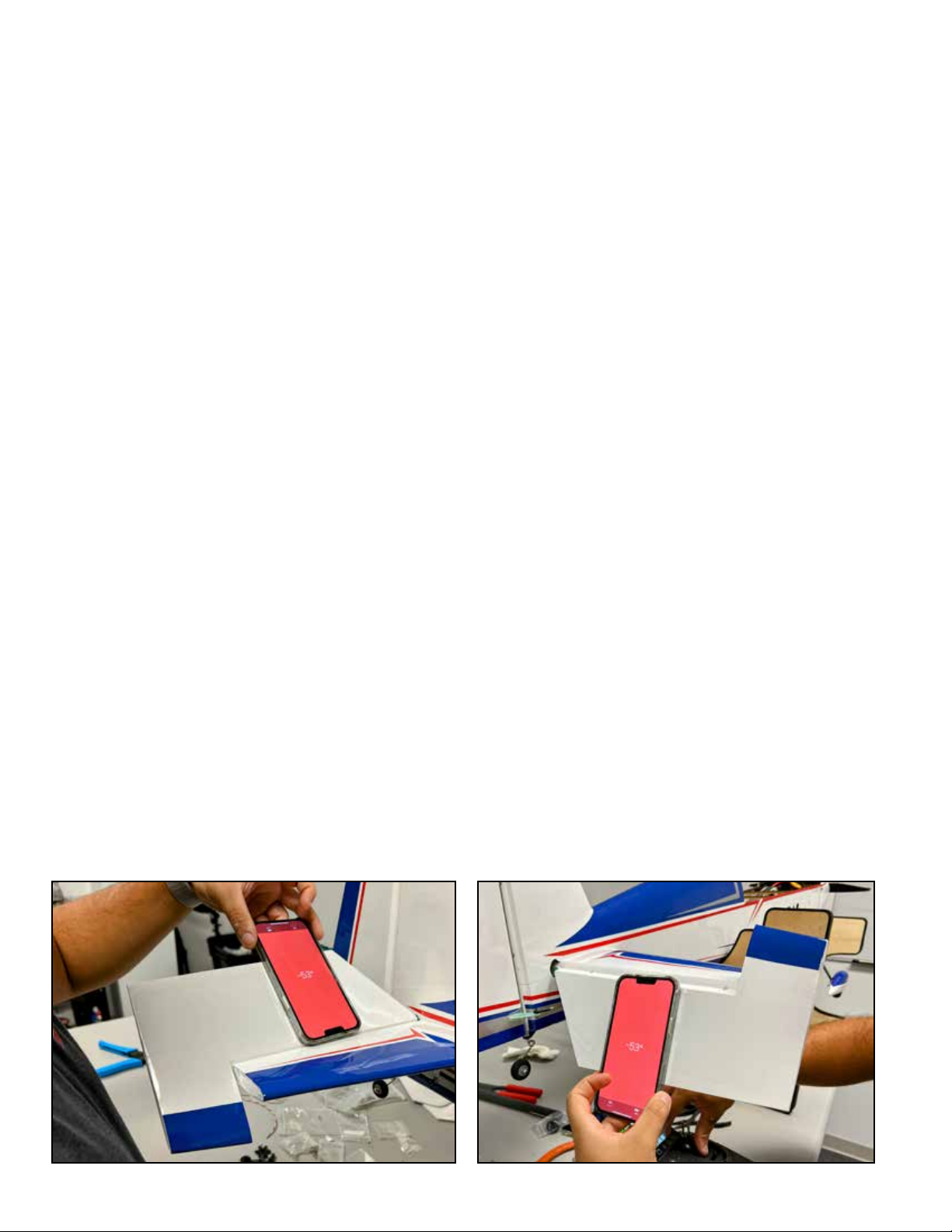
There are various throw-meters available for checking control surface throw,
our favorite is the “level” or “measurement” app on our cell phones. Hold the cell
phone against the surface at neutral, tap the reset on the level app, then deect
the surface while holding the phone in contact.
 Loading...