

Page 1
Page 2

Please read the following paragraph before beginning assembly of your aircraft!
THIS IS NOT A TOY! Serious injury, destruction of property, or even death may result from the misuse of this product. Extreme
Flight RC is providing you, the consumer with a very high quality model aircraft component kit, from which you, the consumer,
will assemble a flying model. It is beyond our control to monitor the finished aircraft you produce. Extreme Flight RC will in no
way accept or assume responsibility or liability for damages resulting from the use of this user assembled product. This aircraft
should be flown in accordance to the AMA safety code. It is highly recommended that you join the Academy of Model Aeronautics in order to be properly insured, and to operate your model at AMA sanctioned flying fields only. If you are not willing to
accept ALL liability for the use of this product, please return it to the place of purchase immediately.
Extreme Flight RC, Ltd. guarantees this kit to be free of defects in materials and workmanship for a period of 30 DAYS from the
date of purchase. All warranty claims must be accompanied by the original dated receipt. This warranty is extended to the original purchaser of the aircraft kit only.
Extreme Flight RC in no way warranties its aircraft against flutter. We have put these aircraft through the most grueling flight
tests imaginable and have not experienced any control surface flutter. Proper servo selection and linkage set-up is absolutely essential. Inadequate servos or improper linkage set up may result in flutter and possibly the complete destruction of your aircraft.
If you are not experienced in this type of linkage set-up or have questions regarding servo choices, please contact us at info@
extremeflightrc.com or 770-887-1794. It is your responsibility to ensure the airworthiness of your model.
Congratulations on the purchase of the 70CC Peregrine from Extreme Flight RC.
Please read over the manual completely before beginning. This will give you an overall understand of the assembly process and
familiarize you with the tools and supplies you will need.
Extreme Flight consantly upgrades and improves its products. Hardware and details may change, but the basic process remains
the same. If you are confused about a step, please call or email us at the contact information on our website, we will be glad to
help.
Special Notes on the 70CC Peregrine:
The Peregrine is a high-performance 3D aerobatic biplane. If you are used to our 3D aerobatic monoplanes, there are a few
dierences to be aware of.
1.The fuselage and cowl area of this biplane are more complex than the same areas of a monoplane. Assembly and setup will
take more time and patience. Please allow extra assembly time compared to a monoplane.
2.The Peregrine is designed to minimize the typical flight ects of the biplane layout, and it is much more like a monoplane in
flight performance than most biplanes. It is not, however, exactly like a monoplane. You will feel more coupling and in general you
will experience dierent dynamics. As you become used to the biplane feeling, however, you will notice the extremely eective
ailerons and rudder, especially at low speed, and you might become a biplane addict, like so many of us are.
3.Because there are four ailerons, you will find the Peregrine very responsive in roll. In the setup portion of this guide, we recommend using a slightly lower aileron throw and slightly more expo than typical on a high-performance monoplane.
4.The Peregrine arrives to you with pre-hinged and gap-sealed surfaces and pre-installed control horns.
5.The Peregrine arrives to you with pre-fabricated gas-engine cooling ducts to be installed in the cowl. These ducts can be easily
modified to function in an electric-power installation. However, we also supply files to 3D print custom cooling ducts for electric
power setups, please consult the 70CC Peregrine page on our website.
6.The Peregrine has a 3-piece cowl. For gasoline installation, the cowl has a conventional top and bottom section attached by
screws, as on many 70CC designs. It also has a quick-latch top battery hatch for electric power installatons. This battery hatch
IS NOT hardened against vibration, since it is not intended to be used in gas installations. For gas, we recommend permanently
installing this hatch with a bead of Goop or clear silicone caulk.
7.The rudder of the 70CC Peregrine installs with a wire in the manner of quick-release rudders. However, the Peregrine is a
relatively small aircraft and so we do not anticipate that very many users will desire to remove the rudder regularly. However, you
certainly can remove the rudder for transport. If you do, it is NOT necessary to restrain the wire pin, it will not fall out in flight. In
this manual we detail our recommendation for a permanent installation.
Page 3
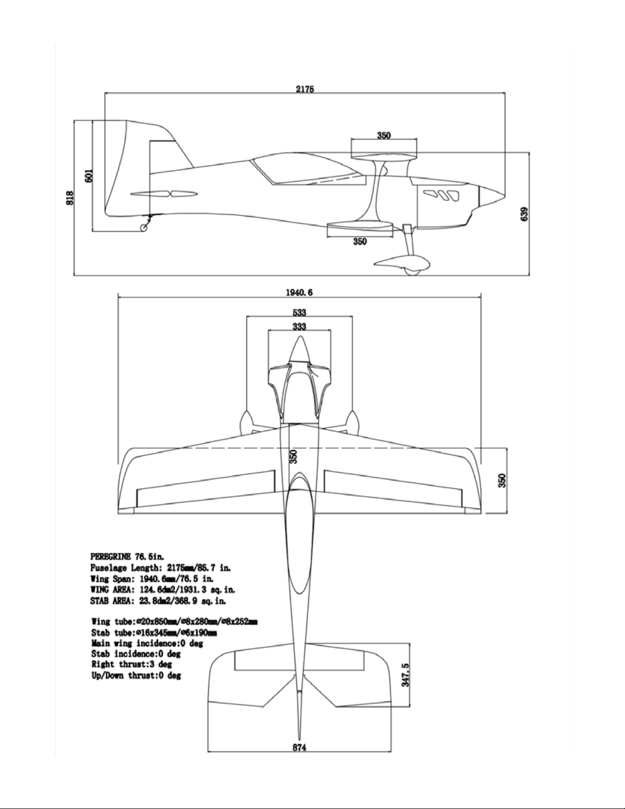
Dimensions and Specs
Page 4

Component Options
Servo choices:
The ailerons of the Peregrine are smaller than typical 70CC ailerons and the load is split between 4 servos, so the aileron servo
recommendation can be less powerful than a 70CC monoplane, but there is no problem using typical 70CC servos, they will be
nicely over-powered. We recommmend to use servos at least 400 oz/in. We recommend QTY 4 Savox either 1270 or 1280 servos
The tail surfaces of the Peregrine are typically-sized for a 70CC airplane, so these servos should be the same rating as other
70CC servos for freestyle aircraft. We recommend servos at least 500 oz/in. We recommend QTY 3 Savox 1270, 1280 or 2290
servos.
Radio system/servo power:
We recommend to power your radio system with lipo batteries. We typically use QTY (2) 2S2000mah. We prefer a “power safe”
style receiver which has HD battery plugs built-in, and a “soft” style radio switch.
If using gas power, we prefer an IBEC, ignition battery eliminator circuit, such as the Tech-Aero IBEC.
Gas Power:
We highly recommend the GP 76CC or DA 70CC engines. The Peregrine was designed around and tested with these gas engines.
Other 70CC class gas engines are compatible, but may require customization of the cooling ducts. It is possible to fly the Peregrine on 60CC class single cylinders, but expect to need additional noseweight to balance and you will need to design and build
any necessary cooling ducts. Note that the DA70 engine is approximately 4oz lighter than the larger GP76CC. All else being equal,
it requires approx 4 oz additional mass in the nose for a DA installation to balance exactly as a GP.
Electric Power:
We have flown the Peregrine on many dierent kinds of power systems. Here are some recommendations and notes-
XPWR:
Use the XPWR 60CC outrunner and 24x12 carbon electric prop. We recommend the Castle Creations 160HV ESC using ONLY
firmware 4.22, 12S 5000-5500mah lipo. Use the Blazing Star X-Large electric stando set for mounting. This setup provides
approx 6KW for good all-around 3D and sport performance.
Scorpion:
Scorpion Power System oers a couple of power system options depending on your desired flight performance and flight envelope. Their motors pair with suitable Cross Mount and Stando Sets to be a convinient bolt on fit to the front of the Peregrine.
Pair the Scorpion motors with one of the Tribunus ESCs for a matched and optimized power system.
*Standard Setup: (60-70cc)* Electric Recomendation Motor : Scorpion A-6528-200kv + Scorpion A-65 Cross Mount (50cc
- 76cc) + A- Series stando set (30cc-76cc) ESC: Tribunus III 14-150A Prop : 24x10E (wood or carbon) Battery : 12s 5000 5500mah (45C or higher)
*Overpowered Setup: (70cc-85cc)* Electric Motor Recomendation Motor : Scorpion A-7430-185kv + Scorpion A-74 Cross
Mount (50cc - 76cc) + A - Series stando set (30cc-76cc) ESC: Tribunus III 14-150A Prop : 25x12 - 25.5x13E (wood or carbon)
Battery : 12s 5500 - 6000mah
Scorpion as well oers the above power systems in “Plug-N- Power” system combos which come pre soldered, pre programmed,
and pre assembled for easy operation and use.
StinGR Belt-Drive:
The Stingr 85 unit has the correct bolt pattern to mount to the marked firewall, add 19mm standos for the correct length. The
Stingr unit fits without any cowl cuts. See the Peregrine page on our website for downloadable STL files for cooling ducts. Please
see Stingr technical information for compatible ESCs. Prop - 25.5x13 Falcon carbon electric or 25x12 XOAR PJN. Lipo - 12s
6000-8000mah.
Page 5
Your aircraft has been on a journey around the world since it left our factory. Although the covering material was perfectly
smooth when it was boxed up, changes in weather and humidity may have wrinkled the covering material. For certain, wrinkles
will appear in the covering once you have unpacked your aircraft and it adjusts to the atmospheric conditions in your region.
Learning to remove wrinkles from covering is a necessary skill to maintain your wood aircraft.
Your Extreme-Flight produced aircraft is covered in Ultracote covering material (US market name), also called Oracover in global
markets. If you need replacement covering to repair damage, Ultracote/Oracover is widely available from retail hobby suppliers.
Also, each roll of Ultracote/Oracover includes excellent instructions which are also available online. Please refer to them for
details about working with and/or repairing your covering.
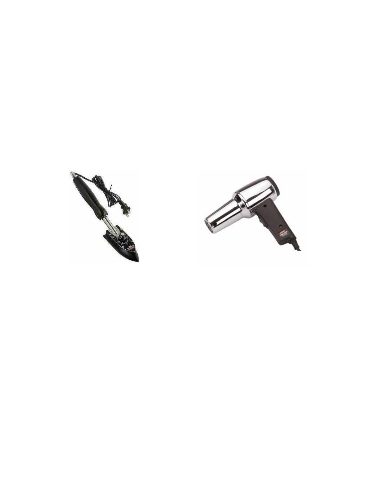
The basic tools are a covering iron and a hobby heat gun. Start by using the iron at 220F (104C) to seal all of the edges on the
covering scheme. This is CRITICAL on the leading edges of wings and stabilizers. Then use the iron at 300F (149C) or a heat
gun to shrink out any wrinkles in the covering. Remove the plastic canopy from the aircraft when using a heat gun to protect it
from heat damage. GO SLOWLY AND CAREFULLY to avoid over-shrinking or burning the covering. This is a skill which takes a
bit of practice. There are many tutorial videos online demonstrating shrinking wrinkles from Ultracote.
Repairing covering and paint
Small sections of covering are included in your kit box to help with any small covering repairs. If you need to purchase an entire
roll of Ultracote or Oracover, the product codes are listed below. If you need to repair painted surfaces, if you do not wish to go
through the entire procedure of having matching paint mixed up a local auto paint company, you can obtain very close matches
using the RAL international color code system. In most parts of the world, small and inexpensive spray cans of paint are available to order according to the RAL code. In the USA, one supplier is lvppaints.com. Note that RAL codes only cover non-metallic
colors and do not cover black.
Ultracote colors Oracover colors RAL Color codes
RED color scheme:
HANU866 true red 21-023 ferrari red RAL 3000
HANU881 silver 21-091 silver
HANU874 black 21-071 black
HANU910 carbon fibre 421-071 carbon
HANU870 white 21-010 white RAL 9010
GREEN color scheme:
HANU903 apple green 21-043 May green RAL 6018
HANU881 silver 21-091 silver
HANU885 midnight blue 21-052 dark blue RAL 5013
HANU874 black 21-071 black
HANU910 carbon fibre 421-071 carbon
HANU870 white 21-010 white RAL 9010
Page 6
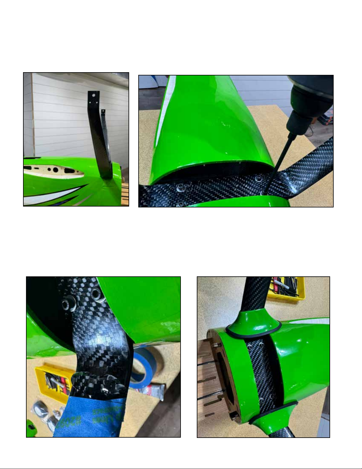
The Peregrine uses a carbon-fiber high strength landing gear. The 70CC Peregrine landing gear sweeps BACK when properly
installed. See photo.
The landing gear installs onto the fuselage using four M4 screws and washers, which thread into pre-installed blind nuts in the
fuselage. Use blue loctite here. Your kit includes landing gear-to-fuselage fairings made of fiberglass. The fairings may need to be
fit to the landing gear legs, use a folded piece of sandpaper if you need to open the fairings. Test fit these fairings to find the best
fit, then attach to the landing gear legs with a dollop of GOOP rubberized adhesive or Gorilla Clear Bond adhesive. Use some
masking tape to hold the fairings in position if necessary. Allow to cure.
Page 7
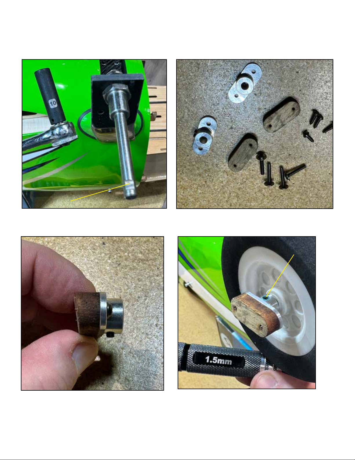
Install the axles onto the landing gear using the self-locking nuts, tighten with a 10mm socket or wrench. Each axle has a flat
spot on the end, orient it to point DOWN, toward the runway, when the plane is upright. The wheel retainers incorporate a wheel
pant support. Assemble the retainer and support as shown, install the wheel and then the support, using loctite where indicated.
Flat Spot
Loctite here
Page 8
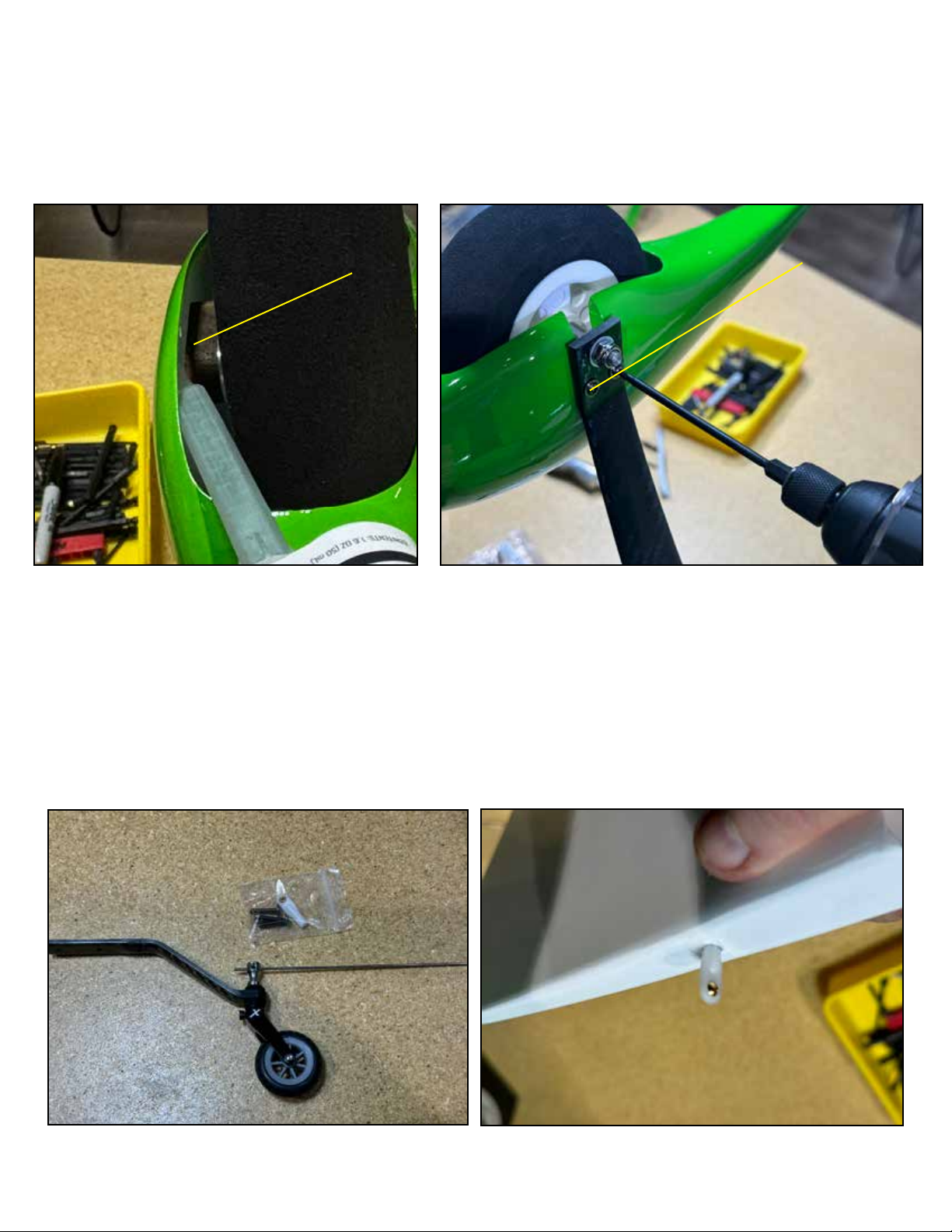
Install the wheel pant over the wheel and axle, apply loctite and start the M3 screws which retain the pant to the gear, but do not
tighten.
Flex the pant away from the retainer and apply some epoxy glue between the retainer and pant. By stabilizing the pant, this
design lengthens the life of your wheels pants.
Fully tighten the retaning screws for the pants and allow the epoxy to cure.
epoxy glue here
Loctite here
Install the rudder tiller keeper (we use a small nylon ball link for this purpose) in the bottom of the rudder as shown with epoxy
glue. There is a pilot hole in the correct location.
Page 9
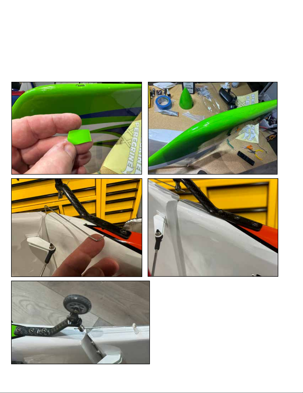
Install the rudder with the wire pivot through the hinges. You can certainly leave the wire pivot exposed on top of the rudder
so that the rudder can be removed for transport. If you do so, it is NOT necessary to restrain the wire pivot, it will not fall out in
flight. However, since the peregrine is not an extremely large aircraft, we do not expect very many users will want to remove the
rudder. For this build, we elected to permanently install the rudder, and we made a slit cut into the top of the rudder and pressed
the bent portion of the wire into the slit and covered it with a small piece of covering included in the kit.
Alternately the rudder pin can also be installed from the bottom, bent, and retained by placing under the tailwheel bracket as
shown.
Once the rudder is installed, attach the tailwheel to the fuselage using M3 screws and loctite, feeding the tiller wire into the tiller
keeper as shown.
Page 10
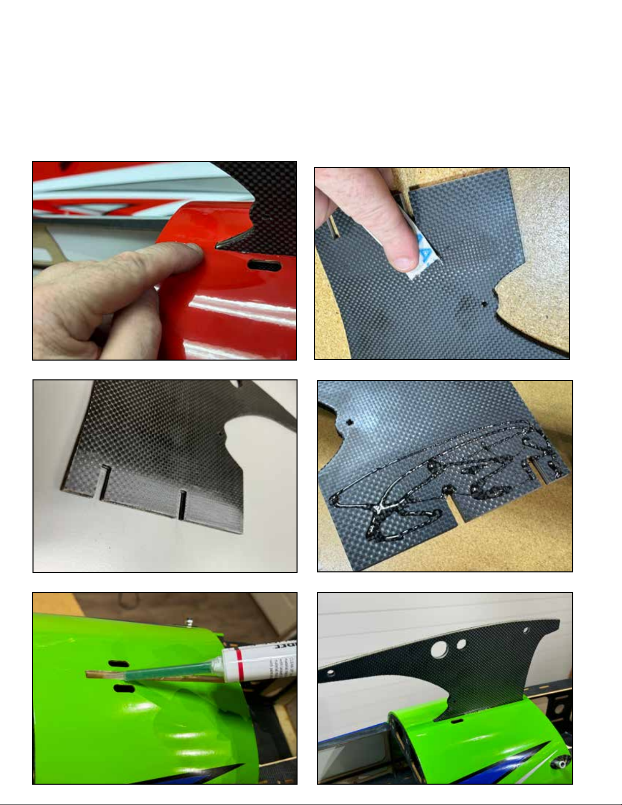
The Peregrine uses a center strut, called a “cabane” strut. The cabane strut is permanently glued into the fuselage. Test fit the
cabane into the fuselage as shown WITHOUT glue. The cabane sits down in the slot onto a structural floor piece in the upper fuselage. Push the cabane down until it solidly seats on this floor piece and the rear corner of the cabane is flush with the fuselage
skin.
Once you are satisfied that you have the cabane fit, remove it and scu the gluing area with sandpaper. Clean this scued area
with alcohol, allow to dry and then apply generous epoxy glue to the cabane and into the slot as shown. Push the cabane strut
down into the slot and seat it. Epoxy will push out of the slot both on top *and inside the fuselage*. Clean up the excess with
alcohol.
Page 11
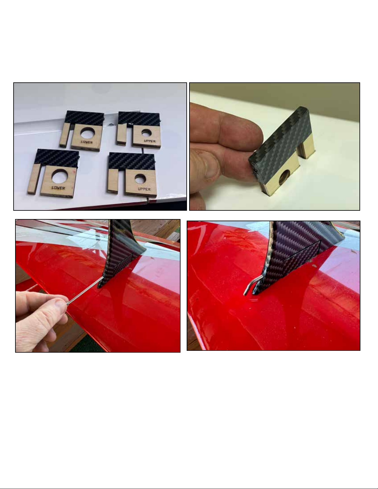
In-between the wings there are struts called “interplane” (between the planes of the wings) struts. These are quick-release with
steel pins which hold them in place for flight. Locate the four interplane strut mounts as shown, they are marked to indiciated
which wings they mount into, upper or lower wings. These mounts epoxy into the slots in the wings. Test-fit them and make sure
you know where they go and verify they push all the way into the slot. Once you are satisfied with the fit, apply epoxy glue to
mounting area and install permanently. Clean up any excess epoxy with alcohol.
Page 12
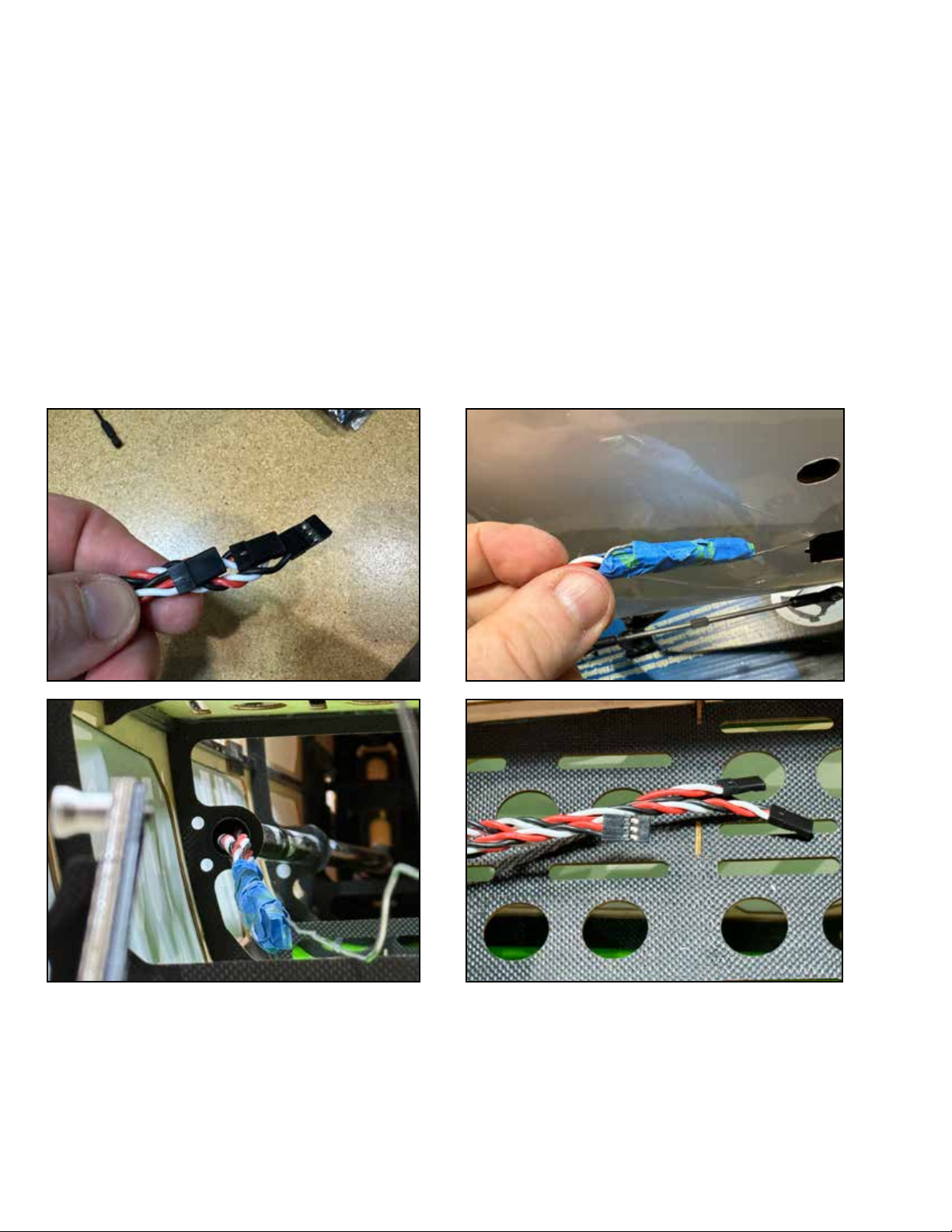
The 70CC Peregrine uses the following servo extension wires and connectors:
Elevator servos: 2 x 36”
Rudder servo: 24” (this is the lightest option. A 36” will be a bit easier to work with at the cost of a tiny amount of weight)
Throttle servo (or ESC): 24”
Upper wings: 2 x 3-6” (depends on the length of the servo leads)
2 x 24” (from upper wing connection point on cabane strut to receiver)
Lower wings: We recommend MPX 1-wire connectors to connect the wing panel to the fuselage.
2 x 12” (from MPX connector to receiver)
The Peregrine has a plastic tube installed in the rear fuselage to guide the servo extensions wires. We recommend to connect
the 24” extension to the rudder servo before running the extensions through the fuselage. One technique is to use electrical sol-
der (it’s a good combination of stiness and softness to work with) and run it through the tube from the front. When it reaches
the rear, use masking tape to connect the three tail extensions to the solder and pull them through the fuselage.
Page 13
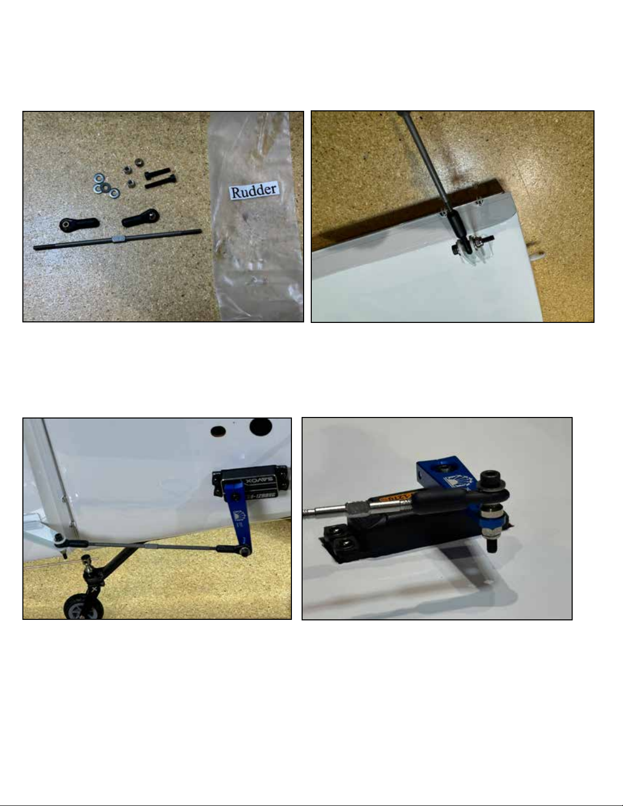
Assemble the rudder pushrod by screwing the ball links onto the metal turnbuckle as shown. Note that, to make the pushrod
length-adjustable after installation, one end is right-hand threaded, the opposite end is left-hand thread. Install the rudder pushrod to the rudder horn as shown. Note that the rudder pushrod and other pushrod hardware bags included both long and shorter
M3 screws. For some servo arms, the long screw might be a necessity to allow enough threads for all spacers and locking nut.
The rudder servo fits into the side of the fuselage in the pre-fabricated mounting locations as shown. On ALL mounting locations
on the Peregreine, the opening should be tight to the servo body, you may need to open the location by a tiny amount to fit your
particular servo, as the sizes of servo bodies are not precisely standardized. See the proper attachment of the pushrod on the
servo arm side. It includes a cone-shaped spacer and locking nut, attach all pushrods to servo arms in this way.
We recommend a 2” length servo arm for the rudder, as we do for the elevators. In our testing, on most brands of servos and
radio systems, we are able to use the 1.75” location on the arm and achieve full throw with maximum torque and resolution.
Please check this during your servo throw setup. On some setups, we can even use a 1.5” location on the rudder, but this is
dependent on the individual pilot’s preference for rudder throw, so this is an option to examine during flight testing.
Page 14
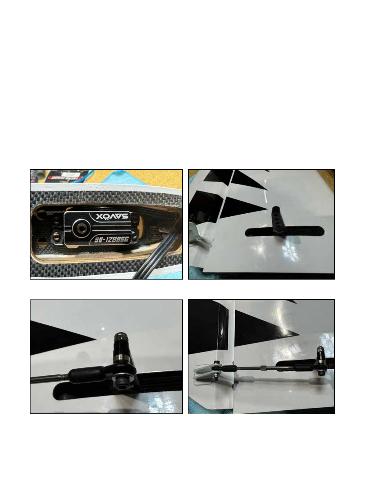
To make the horizontal stabs on the Peregrine easily removable, the elevator servos mount inside the stabilizers. This is common
on giant scale aircraft; if this is the first time you have encoutered this style of elevator servo mount, note that the first time you
assemble one it will require some patience. After you have done a few it will become easier. Note that the servo orientation will
be correct when the servo arm is located in the center of the slot in the stabilizer. Take a moment and familiarize yourself with
the orientation of the servo, the output shaft goes to the rear of the airplane. Widen or lengthen the mounting slot as needed for
your particular servo, we prefer a hobby knife and then a sanding board, but many tools can be used.
Install the servo, then install the arm, rotating the servo arm to allow tightening the pinch bolt on the servo arm. Again, if this is
the first time you have mounted a servo inside a stabilizer, it might take a bit of patience, but will quickly become familiar.
The slots in the stabilizers are cut for the most common servo/arm combinations, but some combinations will require either
shims between the servo and the mount to move the servo, or trimming the slot to widen it. Build and install the pushrods as
shown, again noting that one end is right-hand thread and one is left, to allow changing the length after installation by rotating
the metal turnbuckle body. Also note that two lengths of M3 screws are supplied, use them on the servo end or control horn end
as needed to allow enough threads for the locking nuts.
As on the rudder, we are often able to use the 1.75” mounting location on the 2” servo arm and still achieve the desired throw at
maximum torque and resolution.
Page 15
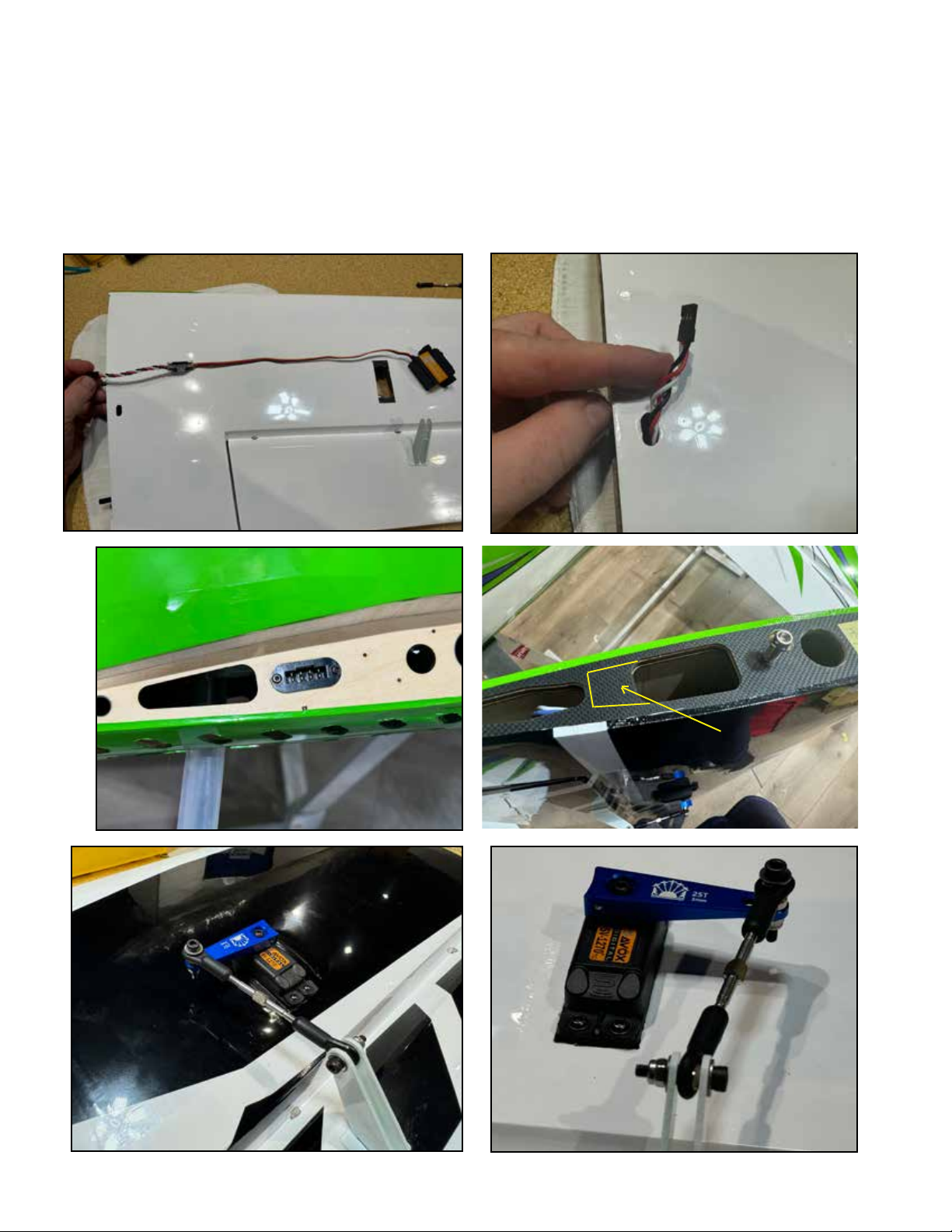
The Peregrine uses 4 aileron servos, one in each wing panel. Start by checking the total length of your servo wires. On the upper
wings, a short wire extension is required. For this build using Savox 1270 servos, a 3” extension is correct. We recommend a 3”6” extension for this location in case your servo lead is shorter. Use a lock or tape on all extenions connections as shown. On the
upper wing panel, the servo wire comes out of the wing through the small slot on the bottom side of the panel as shown.
For the bottom wing panels, if you use the recommended MPX connector, no extension is required. If you do not use the MPX, a
3-6” extension is required. NOTE: ON EARLY PRODUCTION KITS THERE IS AN INTERFERENCE. To use the MPX connector on
the bottom wing, it is necessary to open the port in the root rib as shown. Apolgies for this inconveneince.
Mount the servo with the output shaft to the front, assemble and install the pushrods as you did on the other surfaces. We rec-
Remove for MPX
Page 16
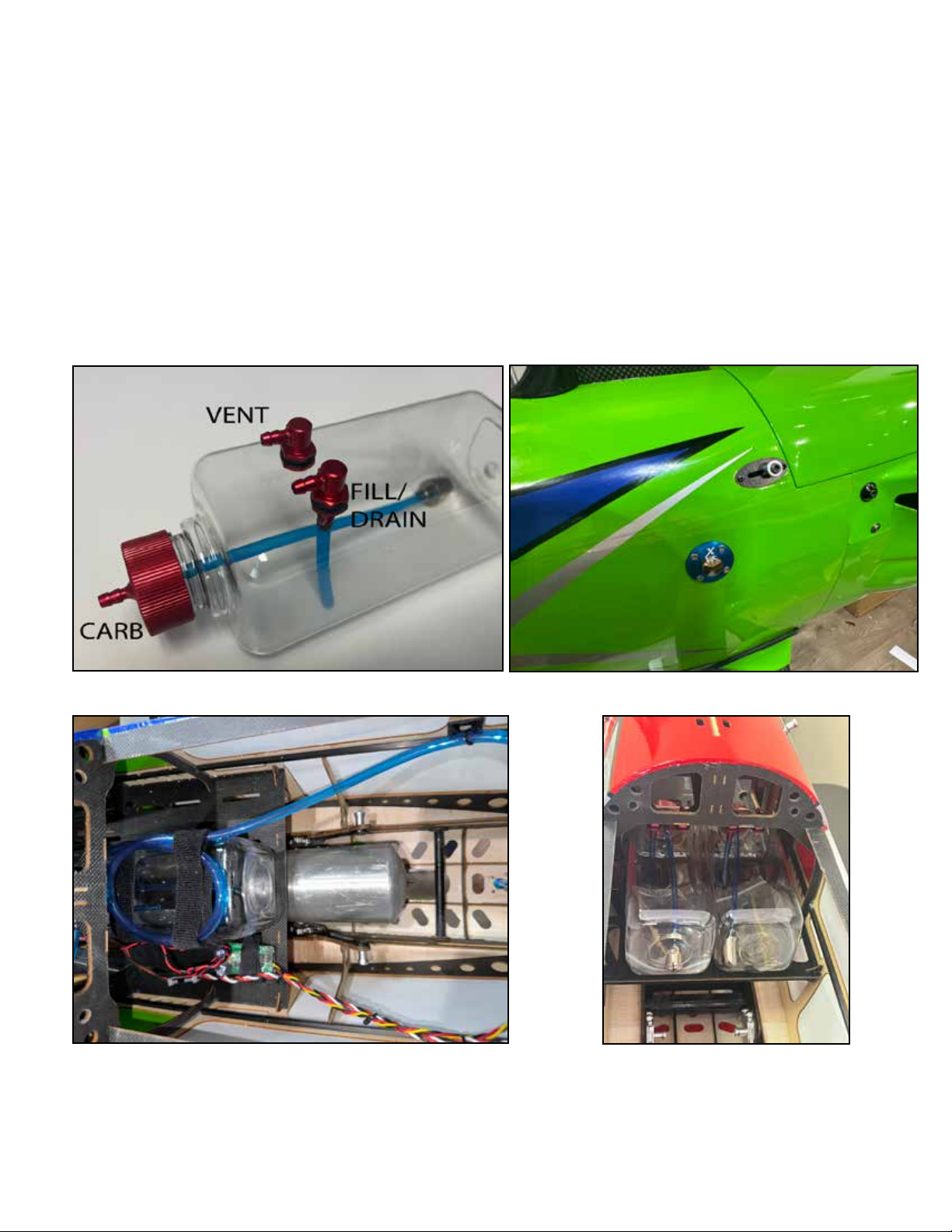
The fuselage of the Peregrine is dierent from the fuselage of our other aircraft, especially monoplanes. If you are used to building giant-scale monplanes, working inside the Peregrine is going to take more time and eort, being a compact biplane. Take
some time to familiarize yourself and form a plan for installing your fuel system components.
We recommend a 24 oz. fuel tank for 70-76CC use. Normally we mount the tank into the fuselage of an airplane before attaching the plumbing, but in the tight confines of the Peregrine, it is easier to attach the lines first and THEN place the tank on the
tray and apply velcro straps to it. We recomend to use self-adhesive velcro to attach the tank to the tray and then applying two
strong velcro straps around it.
Note that we put a loop in the vent line to prevent fuel siphoning out of the tank in aerobatic attitudes. Also note that there is
room for a fuel and a smoke tank on the tray if desired.
Page 17
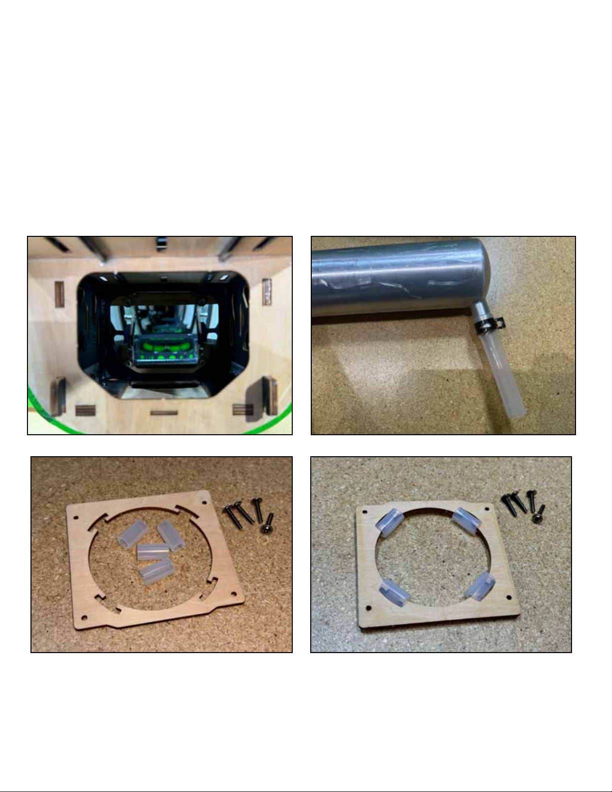
The 70CC Peregrine accommodates the MTW TD-110H rear-outlet canister muer. This is paired with the 60mm drop DA-70
Y-header, which fits either the DA-70 or the GP-76 engine. The kit has mounting and outlets for the TD-110H included and built
in, but because the peregrine fuselage is narrow and compact, the installation procedure is unique and must be followed exactly.
Remove the wood cover plate in the front of the fuselage to reveal the canister muer mount area. The 110H canister outlet
tube must be shortened. A hacksaw, dremel tool cuto wheel or razor saw can be employed. We shortened ours to 30mm. After
installation, we replaced the missing length with 3/4” silicone tubing (we got ours from amazon.com) and a 3/4” metal hose
clamp (also Amazon).
Locate the canister mount and silicone cushion tubes, install them onto the mount a shown.
Page 18
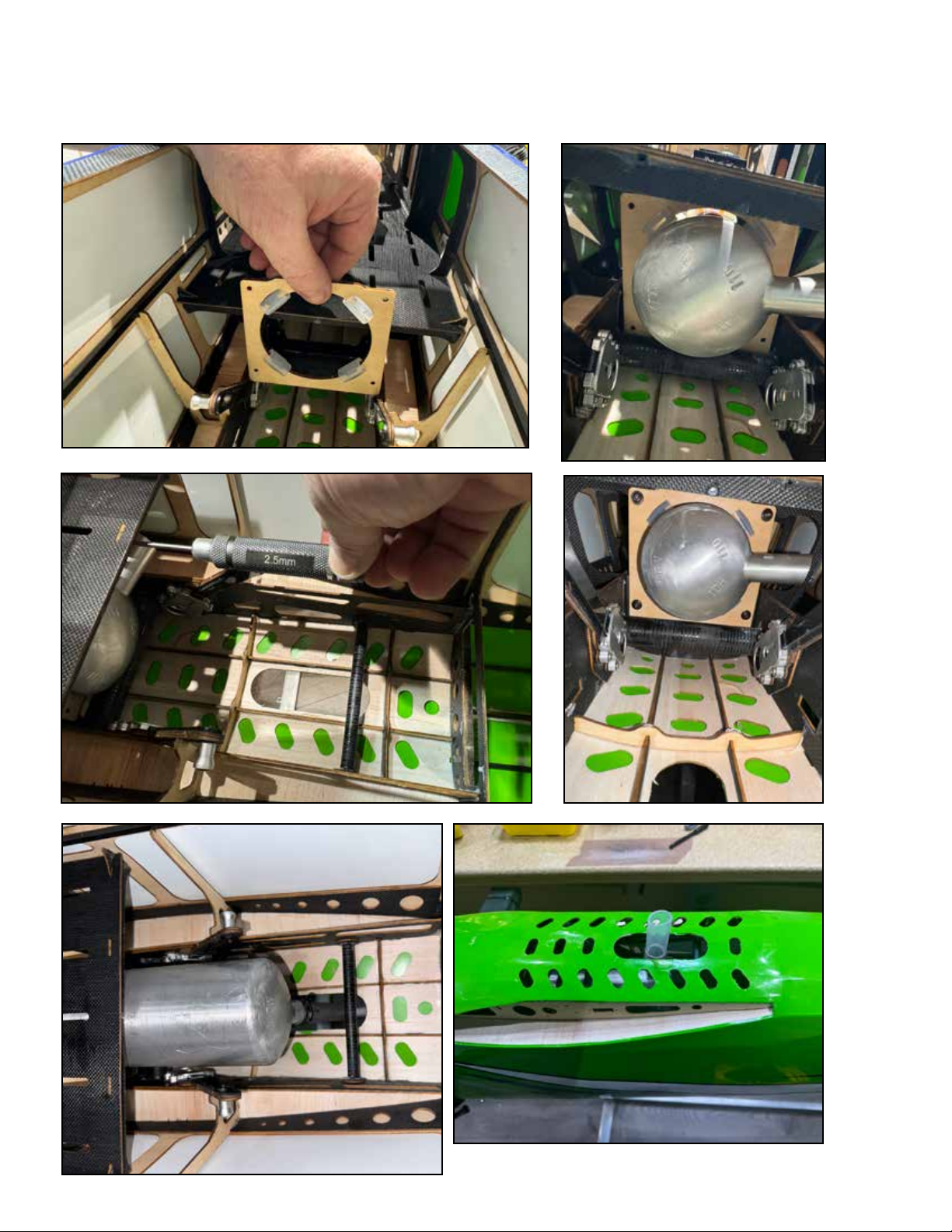
Place the mount into position as shown from the rear, allow it to sit, loose, against its mounting area in the fuselage. Insert the
canister muer into the fuselage from the front, twisting as necessary to feed the outlet pipe through the fuselage. As the rear
of the canister moves past the mounting area, slip the mount over the canister. Be patient. Once the mount is slipped over the
can, add the M3 mounting screws with loctite as shown. Then feed the canister farther back and rotate the outlet into position
over the exit in the bottom of the fuselage. Remove the covering over the exit and the cooling holes around it. Add the silicone
extension and clamp.
Page 19
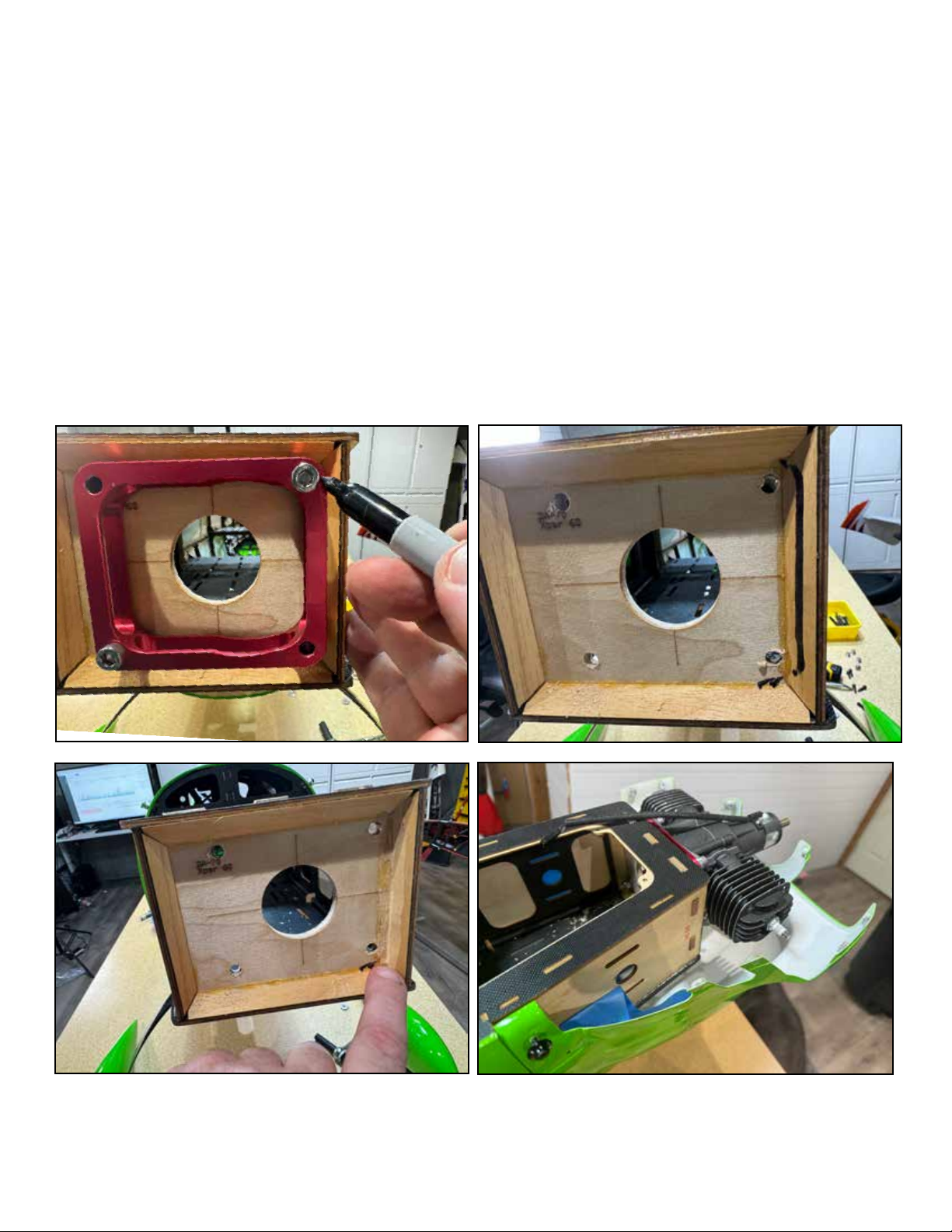
The 70CC Peregrine is intended for 70-76CC twin cylinder gas engines and many of the dimensions and shapes are specifically
fit to these engines, especially the Desert AIrcraft DA-70 and the Great Power GP-76CC. Other 70CC class twins can be used
but expect to do a little fitting of the cooling pieces.
The cowl of the Peregrine is much larger and more complex than a typical 70CC class cowl. It is subject to a bit more dimensional error than smaller cowls during the molding process. We recommend, when drilling the firewall for your engine, that you
drill ONLY two holes, upper left and lower right, and quickly test mount the engine and test fit the cowl and spinner to verify
perfect alignment. The cowl bottom installs upwards from the bottom and attaches with two long M3 screws. It is possible that
you will need to shift the engine 1-2mm slightly to achieve perfection, and this is simpler to do if you have only drilled two. The
firewall is marked for the location of all of the recommended power plants, the DA-70, GP-76 and XPWR 60CC all use the same
hole pattern.
The length of the mounting is set for the DA and GP using our Blazing Star 70CC mount, which includes shims to set the length
for perfect spinner spacing, or use another type of 19mm/.75” stando. Note than the firewall of the Peregrine is smaller and
narrower than a typical 70CC firewall. You may need to remove some of the triangle stock firewall bracing to allow room for your
mounting.
Page 20
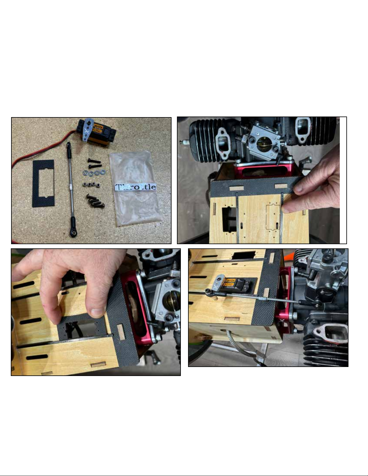
The Peregrine has two alternate throttle servo locations on either side of the motor mounting box. Choose the one which best
suits your engine/carburetor and glue the servo mounting plate on that side using either CA or epoxy glue. Install the servo with
a 1-inch arm and install the pushrod as shown using locking nuts. Note that on many engines, the connection of the pushrod
ball joint at the carburetor throttle arm is tight, and it may require shortening a screw to get clearance for smooth motion of the
throttle. Don’t ever allow any binding or interference on your thottle control.
We recommend spending time now to fully set up your throttle system in your radio. Throttle set up is much easier to accomplish
when there is no cowl or exhaust in the way to obstruct your access.
Page 21
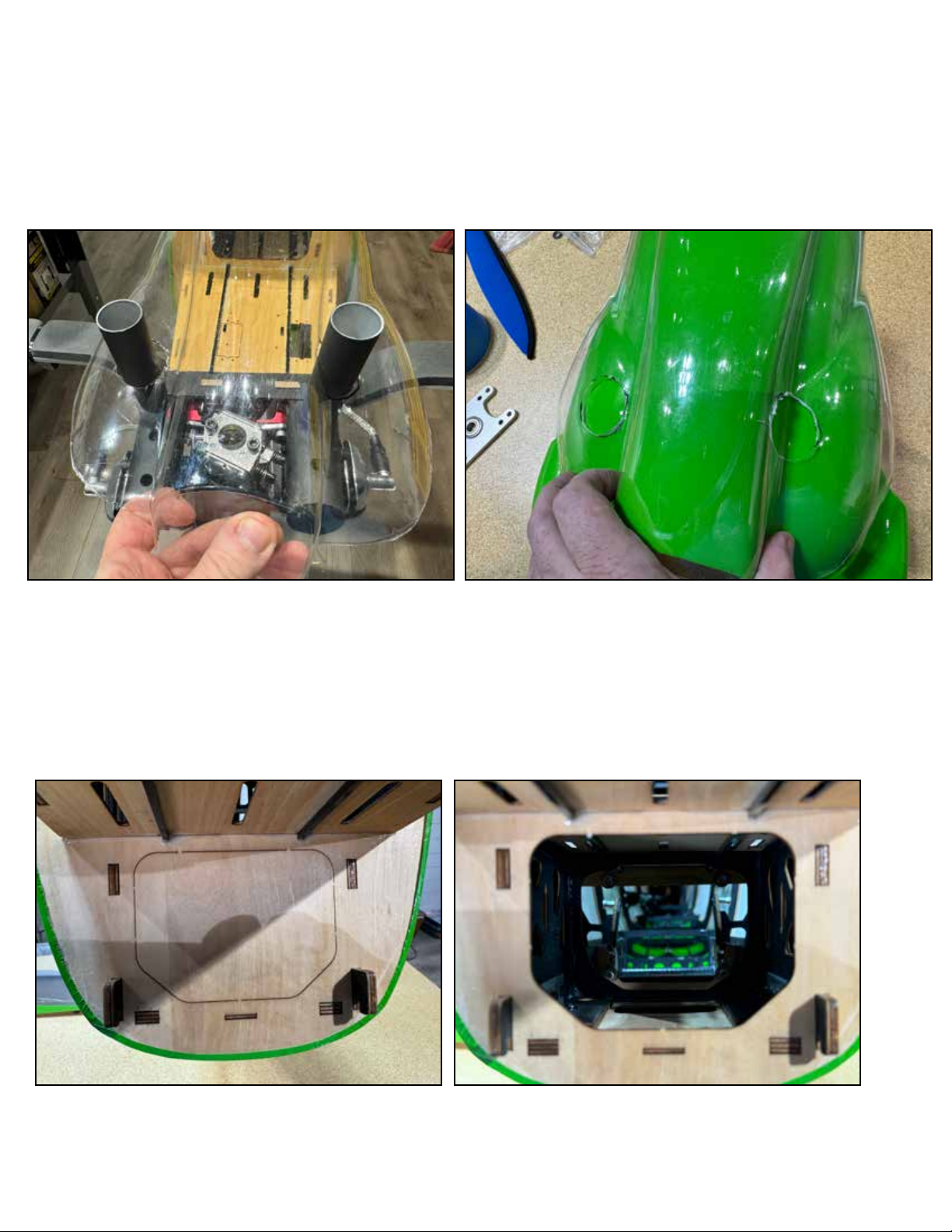
The Peregrine can also use “stock” or “in-cowl” muers on its 70-76CC engine. The use of these muers requires cutting holes
in the bottom of the cowl for exit. Your kit includes a clear plastic marking tool to assist in locating these holes accurately. Install
the muers onto the engine and mark and cut the clear plastic tool until the holes are perfect, then place the tool over the cowl
bottom and mark the cowl for cutting. When cutting into the fiberglass cowl, wear eye and skin protection. Also, depending on
whether your choke linkage exits fom the bottom or the front of the cowling, you can use the clear plastic tool to find the correct
location to cut for the linkage to exit.
If you are using stock, in-cowl muers, you have the option to open the port in the bottom front of the fuselage, or not. The only
reason not to open it is if you will use a smoke system. Leaving it closed can help to keep smoke oil residue out of the fuselage,
however in this case you may need to cut some cooling vents in the bottom of the cowl to exhaust muer heat. If you are not
using smoke, definitely open this port and open the cooling holes on the bottom of the fuselage.
Page 22
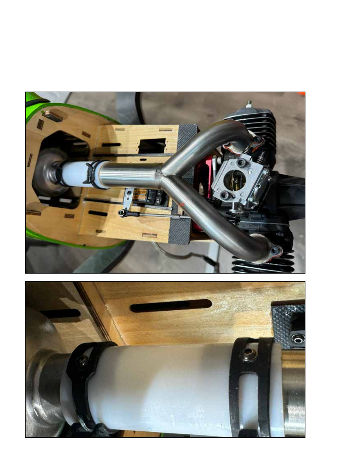
After the throttle linkage is in place, you can finish the installation of the exhaust header and coupler. Frequently, there is interference between the Y-header and the fuel nipple/fuel line to the carburetor. The fuel inlet into the carburetor is a press-fit
and can be turned for clearance. This is often scary the first time. If you are unsure about turning the fuel inlet, we recommend to search the subject online, you can find the procedure and read about replacing damaged fuel inlets if needed.
We recommend to drill two small holes and install two self-drilling screws into the exhaust coupler/clamps as shown to
prevent the coupler coming loose in flight.
Page 23
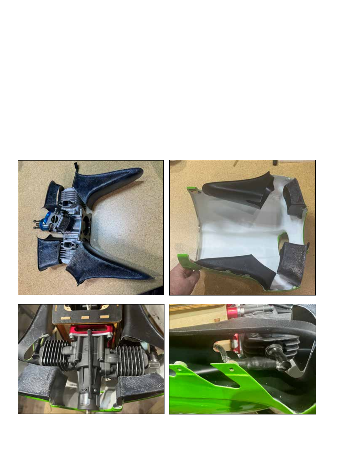
The Peregrine has a unique cowl setup which has direct flow-through cooling tunnels for the engine cylinder heads. It takes
more time to set up than a typical cowl. The setup consists of inlet ducts which take air from the front of the cowl to each
cylinder head, and exit ducts which take the air from the heads to the side outlets of the cowl.
The inlet ducts are relatively simple, just make sure they have enough clearance so you can remove and install the cowl, and
glue them to the lower cowl half with epoxy or anothert glue of your choice.
The extractor ducts will take more attention. Please see photos, you will need to cut them so they have enough clearance
so the cowl can be removed and installed, and also cut them to clear your spark plaug wires as shown. When complete, glue
them to the bottom cowl half.
NOTE: The ducts are made of very lightweight fiberglass, then can be cut easily with scissors. When all of the cuts are complete, the edge can be smoothed with sandpaper as needed, but it is not neccessary to use motorized tools to cut them.
Page 24

For outrunner electric setups, it is easy to convert the gasoline ducting to work. Cap the rear of the inlet ducts with balsa or
foam and cut the inner wall of the duct to allow the air to escape toward the motor.
OR, if you prefer, refer to the 70CC Peregrine page on the Extreme FlightRC.com website for links to 3D printing files for
cooling ducts for various electric power systems.
Page 25
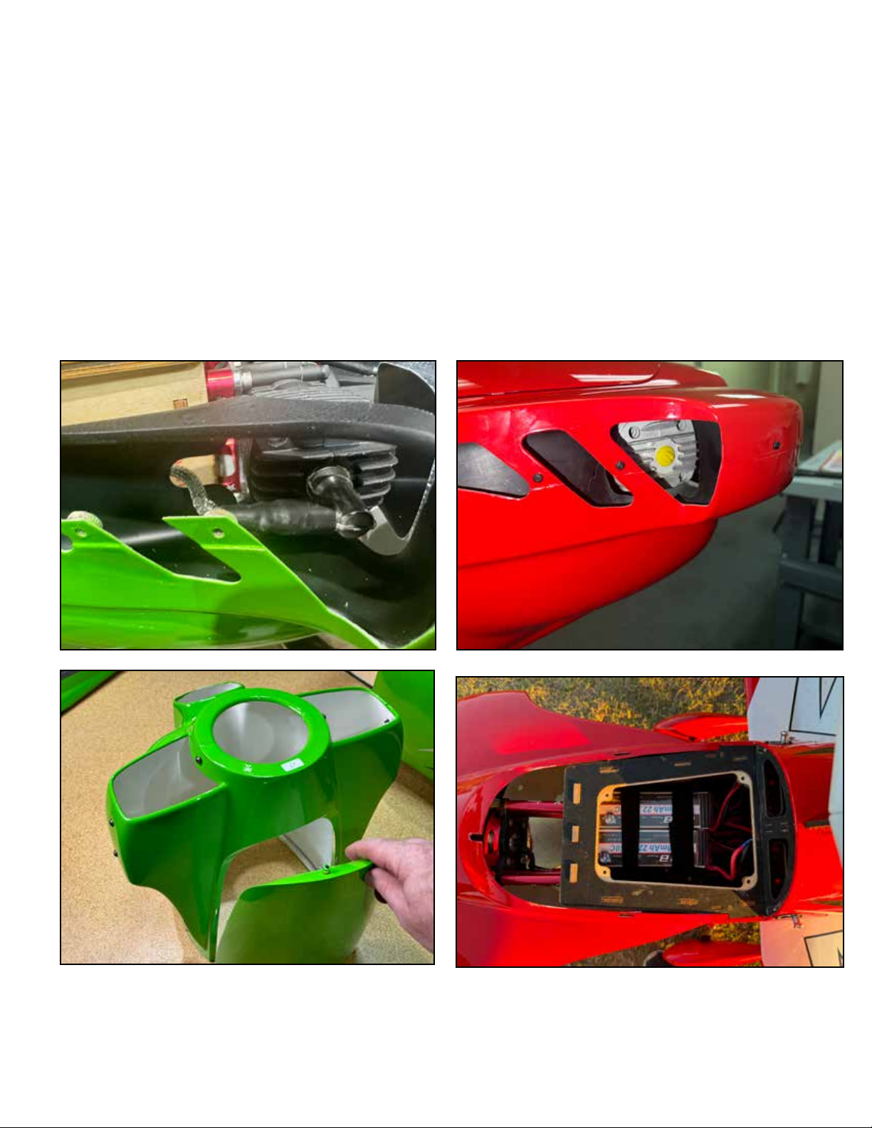
Once your cooling ducts are finished, you can installed the top half of the cowl with screws. Note that these screws thread
into blind nuts installed in the lower cowling piece. If you have owned 70CC+ sized aircraft in the past, you are likely familiar
with this kind of 2-piece cowl. If not, be careful when installing the screws. Make sure they thread easily into the nut and
never force them. Also we like to install these fasteners dry, without loctite. Using loctite on these screws makes it to likely
that you will damage the mounting of the blind nut when removing them.
The Peregrine includes a battery hatch door integrated into the upper cowl half. This is for electric flight use only, it is not
hardened against vibration the way a gasoline hatch door is. If your power system is gasoline, we recommend to do your
maiden flight and verify that everything is proper, and then apply a bead of silicone glue or rubberized glue such as Gorilla
Clear Bond to the battery hatch mounting flange and install it semi-permanently. You can always use a hobby knife to slice
the glue and get the battery hatch open if necessary, but for regular maintenance of your gas engine, we recommend you
remove the upper cowl half as on a conventional 70-120CC plane with two-piece cowl.
Page 26
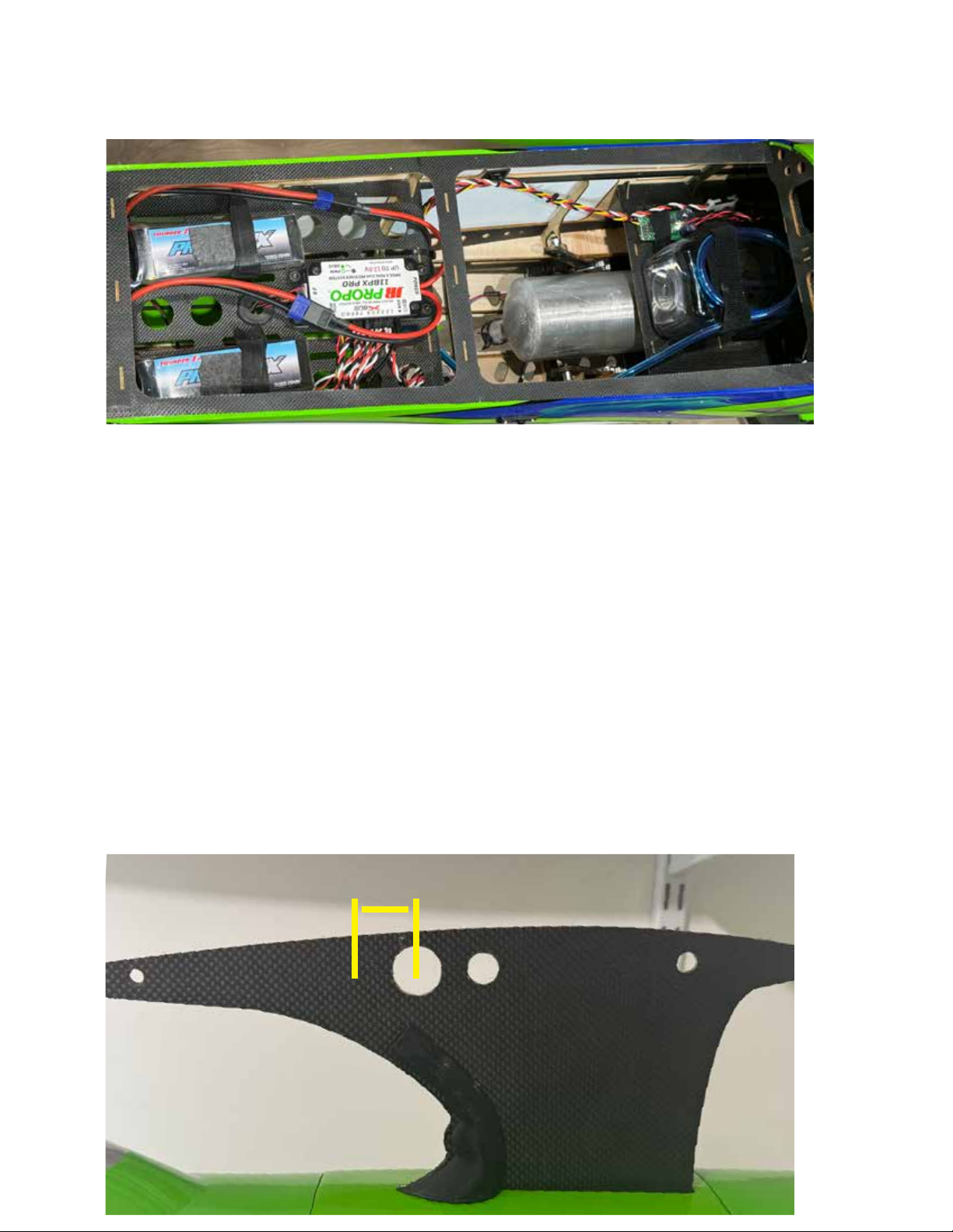
Mount your ignition unit inside the motor mounting box, holes are provided in the sides of the box to run your ignition wires
out through. Mount your Receiver as shown on the rear tray. You can mount your receiver batteries either alongside the
receiver as shown, or alongside the fuel tank if you need more weight toward the nose.
Balance the Peregrine with NO wings installed. Install the horizontal stabs (which use one large and one small carbon tube),
prop, spinner, canopy hatch, batteries...except for the wings it should be ready for flight. We balance with an empty fuel tank;
the fuel tank on the Peregrine is very near the CG anyway, so it matters little if it’s empty or full. The Initial CG range of the
Peregrine is as shown. Pick the plane up (again, no wings) by the cabane strut in the range shown. Hanging the plane level
by the wing tube hole is the forward end of the range. This gives a precision/sport CG and is great for maiden flights. The
rear range for your maiden flight is approx 3/4” or 19mm behind the center of the tube hole, this gives a 3D/aerobatic CG.
For us, we typically check a fresh 70CC Peregrine by lifting by the spar tube hole, and if it hangs level or slightly tail-down,
we’re ready to maiden. The 70CC Peregrine is very stable across the entire CG range.
After you become used to the Peregrine you can certainly move the CG even more rearward for experimentation. For hardcore 3D flight, you may find that you prefer it at 1” or more. A word about CG - There any many dierent power systems and
component sets that can be intalled in the Peregrine and be successful - IF the plane is properly balanced for the individual
pilot who flies it. Our preferred method of tuning CG is NOT to move components around at the flying field. Lipo battery
hold-downs are important and we prefer to work on them in our workshop. Instead, we take some plasticine modeling clay
(children’s or art student’s clay) and we add and subtract it (smashing it into the iside corners of the motor box most often)
until we get our perfect CG. This often takes several flights trying dierent CG’s - easy to do by removing or adding a few
ounces of clay. When you have it perfect, note or mark the location. THEN you can return to your workbench and move components to get this perfect CG in the most ecient way.
Note: in the photo below, we have covered the upper wing aileron extensions with a 3D printed shround for appearance. If
you are interested, you can find a link to the 3D printing files for the these pieces on the Peregrine webpage on our website
- ExtremeFlightRC.com.
3/4 inch / 19mm
Page 27
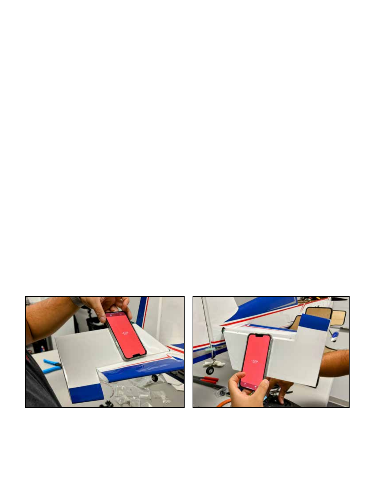
There are various kinds of throw-meters available for this purpose, but our favorite is the smart phone most of us carry every
day. Use a “level” app (most phones come equipped with one) and hold the phone against the control surface to measure deflection as shown.
Control throws:
The 4 ailerons of the Peregrine are very eective. We recommend to set a slightly lower high-rate throw than usual, with more
expo. Later, if you want, you can use as much as you can handle. The elevators are similar in feel to a monoplane and we use
similar throw. The rudder is very eective. We recommend you start with a lower throw than a monoplane and work your way up
if desired.
Initial flights: High Rate Low Rate
Aileron 34 degrees, 50-70% expo 10 degrees, 20% expo
Elevator 50 degrees, 50-70% expo 15 degrees, 25% expo
Rudder 35 degrees, 55-75% expo 25 degrees, 35% expo
Mixing: The Peregrine, being a biplane, requires a bit more mix than our aerobatic monoplanes.
At full high rate rudder, mix in:
RIGHT aileron with RIGHT rudder, 7-10%
LEFT aileron with LEFT rudder, 7-10%
Pitch mix is dependent on CG, at a 3D CG, mix UP elevator on full rudder either direction, 2-4%. At a forward CG, you may need
very little pitch mix.
As you get used to your Peregrine, you can tailor your mixes perfectly to your individual plane. In our test, we actually preferred a
curved rudder-to-aileron mix which increased from approx 5% at center to approx 10% at full rudder, but this is very subtle and
you may find it not worth the eort. Right and left mix, both roll and pitch, are always slightly dierent because these aircraft are
not symmetrical, but use right thrust to counteract prop forces.
Page 28
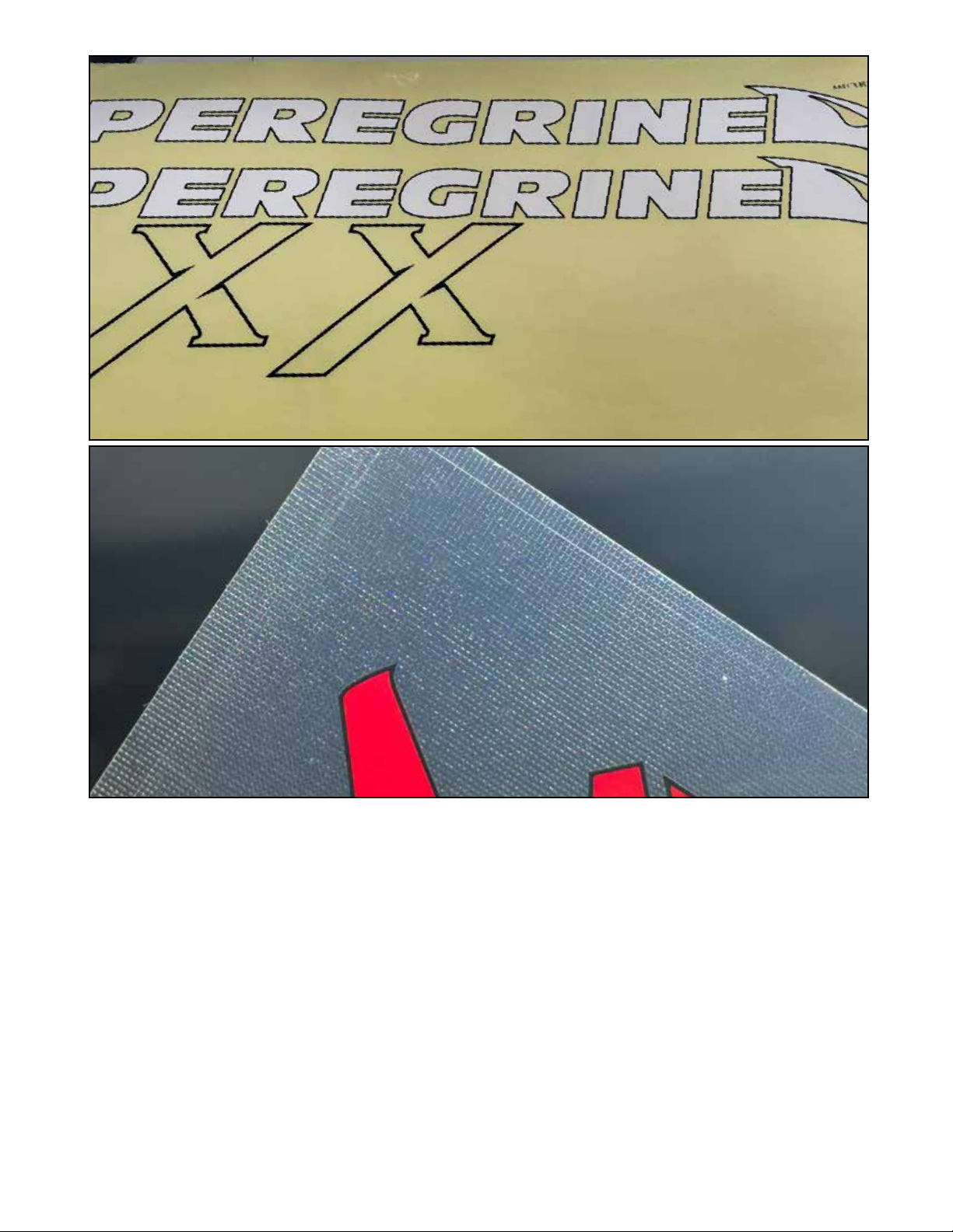
Your kit includes simple adhesive decals made with “air release” material. Burnish them down with a towel or squeegee and
the texture will disappear as any air bubbles are released.
The Peregrine uses quick-latches to attach the wings. Each set of wings uses one large and one small wing tube. Make sure
all latches are attached and locked before flight.
After a short maiden flight, land and:
Check all fasteners
Verify all latches.
Verify battery % to see how many flights you can expect per charge on radio batteries.
Use a good quality spray cleaner/degreser to clean oil o of the plane after a flying session. Periodically use spray wax/detailer on all painted and covered surfaces to keep the Peregrine looking good.
 Loading...