


Thank you for your purchase of the Extreme Flight RC .40 Edge 540T Funfly. Please take a few moments
to read this instruction manual before beginning assembly. We have outlined a fast, clear and easy method to
assemble this aircraft and familiarizing yourself with this process will aid in a quick, easy build.
Please read the following paragraph before beginning assembly of your aircraft!
THIS IS NOT A TOY! Serious injury, destruction of property, or even death may result from the misuse of
this product. Extreme Flight RC is providing you, the buyer with a very high quality model aircraft component kit, from which you, the buyer, will assemble a flying model. However it is beyond our control to monitor the finished aircraft you produce. Extreme Flight RC will in no way accept or assume responsibility or
liability for damages resulting from the use of this user assembled product. This aircraft should be flown in
accordance to the AMA safety code. It is highly recommended that you join the Academy of Model
Aeronautics in order to be properly insured, and to operate your model at AMA sanctioned flying fields only.
If you are not willing to accept ALL liability for the use of this product, please return it to the place of purchase immediately.
Extreme Flight RC, Ltd. guarantees this kit to be free of defects in materials and workmanship for a period of
90 days from the date of purchase. All warranty claims must be accompanied by the original dated receipt.
This warranty is extended to the original purchaser of the aircraft kit only.
Extreme Flight RC in no way warranties its aircraft against flutter. We have put these aircraft through
the most grueling flight tests imaginable and have not experienced any control surface flutter. Proper servo
selection and linkage set-up is absolutely essential. Inadequate servos or improper linkage set up may result
in flutter and possibly the complete destruction of your aircraft. If you are not experienced in this type of
linkage set-up or have questions regarding servo choices, please consult an experienced pilot or contact us. It
is your responsibility to ensure the airworthiness of your model.
Suggested tools and building materials Additional items required for assembly
Hobby knife with #11 blades 4 channel radio with 4 standard BB servos
Phillips and flat head screwdrivers 1 mini servo for throttle
Needle nose pliers .32-.53 2 stroke or .52-.72 4 stroke engine
Thin CA Propeller
30 minute epoxy Fuel tubing
Wire cutters 2.5 inch spinner
Threadlocker Foam padding for receiver and battery mounting
Drill with assorted drill bits Nylon cable ties
Tape measure 2-24 inch servo extensions
Square
Denatured alcohol
Fine tipped marker
1
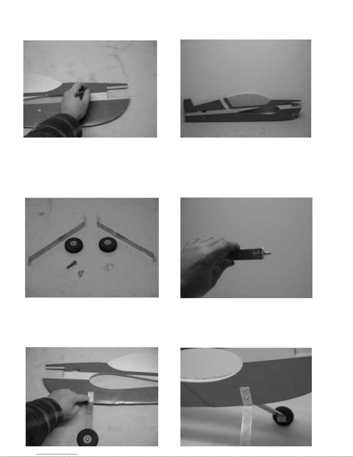
1. Locate fuselage and remove the covering from the throttle servo mounting hole, the wing slot, the
rudder and elevator servo mounting holes and the elevator slot using a sharp #11 blade.
2. Locate the landing gear components including 4 screws, 8 washers, and 6 nylon insert locknuts.
Assemble the axle/wheel assembly first. Place a washer onto the axle screw, then insert the axle
into the aluminum landing gear from the rear side. Place another washer onto the front side of the
aluminum gear followed by a nylon insert locknut. Tighten securely. Place a wheel onto the axle
screw followed by another nylon insert locknut. Tighten until the nut is flush with the wheel, but does
not cause binding.
3. Center the landing gear between the lightening holes just below the leading edge of the wing
slot. The bend in the gear should be even with the bottom of the fuselage. If you are using a lightweight engine you may want to angle the gear slightly forward to help achieve proper CG. Mark the
location of the two mounting holes and drill for the mounting screws. Use a washer on each side of
the landing gear and secure with the 2 nylon insert locking nuts.
2
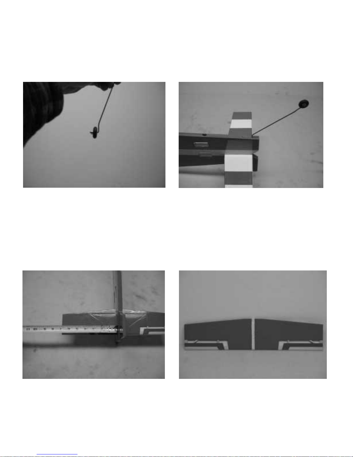
4. Locate tailwheel components including tailwheel wire, tailwheel, wheel collar, and plywood triangle. File a flat area onto the wire where the wheel collar will reside. Place the tailwheel onto the
wire, then the wheel collar. Use thread lock compound on the retaining screw and tighten onto the
flat area. Use a #11 blade to open the slot in the rear bottom of the fuselage. Use a toothpick or
small piece of wire to apply 30 minute epoxy into the slot. Coat the portion of the wire that will go
into the slot as well as the plywood triangle with 30 minute epoxy. Insert the wire into the slot, followed by the plywood triangle. Use a piece of tape to secure the assembly while it dries.
5. Insert the horizontal stabilizer into the slot in the rear of the fuselage. Carefully measure to center the stab in the slot, and measure from a fixed point on the fuselage to the tips of the stab to
ensure proper alignment. Also use a square to to ensure that the stab is perfectly square with the
fuselage. Trim the slot as needed to achieve proper alignment. Make several positioning marks on
the stab with a fine tipped marker so that it will be easy to reposition the stab when gluing it in place.
Remove the stab and using a #11 blade, carefully remove a strip of covering from the stab to allow
for a wood to wood bond between the fuselage and stab. Glue the stab into the fuselage using CA
or epoxy. Use all of the criteria mentioned above to ensure that the stab is properly aligned to the
fuselage.
3

6. Insert the wing into the wing slot. Using the same criteria as used for the stab, center the wing
and check for proper alignment. Again, using a fine tip marker, make several positioning marks to
aid with alignment when gluing the wing in place. Remove the wing and remove a strip of covering
to allow for a wood to wood bond between the wing and fuselage. Glue the wing into the fuselage
using 30 minute epoxy. Check to ensure proper alignment. Use denatured alcohol to remove any
excess epoxy.
7. Use a #11 blade to open the hinge slots in the ailerons/wing, stab/elevator, and rudder/vertical fin
as shown. Place CA hinges into the slots on the control surfaces and mate them to the corresponding slots in the wing/stab/vertical fin. Deflect the surfaces and apply a few drops of thin CA to the
top and bottom of each hinge.
This completes the basic assembly phase of the construction process. Next we will begin
installation of the radio and engine components.
4

8. Next we will install the rudder and elevator servos. Use the manufacturer supplied servo hardware to mount the servos in the rear of the fuselage. The elevator servo mounts in the top hole, the
rudder servo in the bottom. Use a good quality standard servo with a ball bearing supported output
shaft. We have had very good results using the Hitec HS-475 and HS-5475 digital servos in our
prototypes. The HS-225MG and the new HS-5245 digital mini servos also work well for those of you
who want to save as much weight as possible. These servos will fit in the servo holes with very little
modification. We use and recommend the Dubro super strength servo arms to achieve maximum
3D surface travel. At this time you will also want to install the throttle servo. This servo slot is cut
for a mini servo, and we use the Hitec HS-225 in this position.
9. Install the aileron servos in their cutouts in the wings. The servo output shaft should be oriented
torward the rear of the plane as shown in the picture. Use a #11 blade to open the holes for the
aileron pushrods.
5

10. Use a #11 blade to cut a small slit just below the leading edge of the left wing in order to pass
the throttle servo lead into the radio compartment.
11. Locate a nylon control horn and backplate, two small machine screws, one clevis, one pushrod,
one pushrod keeper and one length of heat shrink tubing from the hardware package. Screw a nylon
clevis onto the wire pushrod and attach it to the elevator servo arm. Use this to properly align and
determine the location for the elevator control horn as shown in the photo. Drill two holes through
the elevator to accept the control horn mounting screws. Use the two screws to permanently attach
the control horn to the elevator, threading through the control surface and into the nylon backplate.
Remove the pusrod and clevis from the servo arm and center the servo using your radio. Use a
piece of tape to keep the elevator in the neutral position. This time attach the clevis to the control
horn on the elevator and mark the wire to make a 90 degree bend into the servo arm. Once again
remove the pushrod and make a 90 degree bend in it where it will go into the servo arm. Cut the
pushrod off 1/4 beyond this bend. Reattach the clevis to the elevator control horn and push the
bent wire into the servo arm. Use the nylon pushrod keeper to retain the pushrod at the servo arm.
Slide the heat shrink tubing over the clevis and shrink it with a heat gun to prevent the clevis from
opening. Repeat this procedure for the rudder. The finished linkages are shown below.
6

12. Follow the same procedure as oulined in the previous step to determine the proper location for
the aileron control horns and consruct the aileron pushrods. Center the ailerons to the airfoil of the
wing.
13. Wrap your airborne battery pack in foam and install it into the opening in the servo tray in the
wing opposite the engine. Use nylon cable ties to secure it in place.
14. Attach a 24 inch servo extension to each of the two servos in the rear of the plane. Route both
of these extensions into the channel in the bottom of the fuselage. Use a #11 blade or moto tool
attachment to open a small slit in the bottom of the right wing to allow these two wires to pass into
the radio compartment.
7

15. Use a paper towel and some denatured alcohol to thoroughly clean the bottom of the fuselage.
Locate the strip of blue Oracover and iron it in place over the servo wire channel. Be sure to seal
the edges well using a medium heat setting.
16. Mount your on/off switch on top of the right wing panel near the fuselage as shown in the photo.
17. Place all of the servo wires into their proper slots in the receiver and wrap the receiver in foam.
Place the receiver into the opening in the servo tray on the opposite side of where you installed the
battery. Secure it with a nylon cable tie. Route the antenna along the bottom of the wing or along
the length of the fuselage. We usually route the antenna along the length of the wing, securing it
with a piece of clear tape at the end of the wing. We drill a small hole in the wing tip and insert the
remaining wire back into the wing to prevent it from getting in the way.
8

18. Locate the servo bay hatches and position them in place. Use a 1/16th drill bit to drill through
the hatches and the plywood mounting tabs in each of the four corners. Secure the hatches with the
small wood screws provided in the hardware package. Be sure to drill a hole in the hatch to allow
the antenna to pass through.
19. We have saved engine and tank mounting for last, for a reason. We will use engine position to
help achieve proper CG. Place your engine on the engine mounting rails and check to see if the aircraft balances at the proper CG position. CG on funfly aircraft is subject to the user s preference.
We recommend you begin by balancing the Edge at 1/4 inch behind the main spar for your first
flights. This is a very conservative setting, and many of you more experienced pilots will want to use
a more aggressive set-up. Slide the engine back and forth on the phenolic mounting rails until you
achieve the recommended CG. Mark and drill the engine rails for your engine, then mount the
engine with the screws and nylon insert lock nuts provided.
20. Use the supplied short pushrod, pushrod keeper and clevis to assemble the throttle linkage
assembly as shown above. Your linkage configuration may vary depending on your engine choice.
21. Assemble the fuel tank and position it in place on the opposite side of the fuselage from the
engine. Use the 2 balsa tank stand-offs to allow the tank to clear the throttle servo. Drill 4 holes
through the fuselage, 2 on the top of the tank and 2 on the bottom. Use the 2 provided nylon cable
ties to secure the tank to the fuselage as shown in the photo. Be careful when drilling through the
fuselage that the position of the nylon cable ties does not interfere with the throttle servo. Use silicon fuel tubing to route fuel to the tank and muffler as recommended by the engine manufacturer.
Install your prop and spinner. This completes the construction process!
9

A few words about set-up and trimming
Proper set-up and trimming is absolutely essential to achieve optimum performance from your aircraft. In
addition to balancing your aircraft at the recommended CG position, we highly recommend that you balance the aircraft laterally. Use stick-on lead weight under the wing tip to achieve proper lateral balance.
We recommend the following control surface throws:
Elevator: Low rate: 10 degress both directions
High rate: At least 45 degrees both directions
Ailerons: Low rate: 15 degrees both directions
High rate: 35-45 degrees both directions
Rudder: Low rate: 15 degrees both directions
High rate: As much as possible
Depending on your personal preferences, you will probably want to use a fair amount of exponential to
soften the feel of the aircraft around center stick position. We typically fly these type of aircraft on high rate
settings at all times and use enough exponential to reduce sensitivity around center. The rudder on the
Edge is extremely powerful. If you experience severe coupling in high alpha knife edge, you probably
need to reduce your high rate rudder setting. The Edge is capable of very slow high alpha knife edge with
minimal coupling. Experiment to find the setting that works best for you. If you are new to 3D or are having trouble locking in to high alpha flight, you may wish to mix a small amount of spoileron in with up elevator input. This will cause the ailerons to raise with up elevator input and will help to stabilize the aircraft in
high alpha attitudes. Also experiment with your CG settings to find the best position for a locked in feel.
Our favorite position is 1 inch behind the main spar. Again, this is personal preference.
Right thrust has been built into the engine mounting rails to counteract spiral slipstream effect. Depending
on your engine and prop choice you may need to add a couple of washers under the engine mounting lugs
to increase or reduce the amount of right thrust. Experiment to find the best position for your particular
engine/prop combination.
Take your time and devote the first several flights to properly trimming your aircraft and you will be rewarded with an incredible flying 3D machine. Thanks again for your purchase of the Extreme Flight RC .40
Edge 540T Funfly. See you at the flying field!
10
 Loading...