

Extreme Flight 91"" Yak-54 ARF Assembly Manual
91" Yak-54 ARF
Assembly Manual
Copyright 2013 Extreme Flight RC
1

Please take a few moments to read this instruction manual before beginning assembly. We
have outlined a fast, clear and easy method to assemble this aircraft and familiarizing
yourself with this process will aid in a quick, easy build.
Please read the following paragraph before beginning assembly
of your aircraft!
THIS IS NOT A TOY! Serious injury, destruction of property, or even death may result
from the misuse of this product. Extreme Flight RC is providing you, the consumer, with a
very high quality model aircraft component kit, from which you, the consumer, will
assemble a flying model. However, it is beyond our control to monitor the finished aircraft
you produce. Extreme Flight RC will in no way accept or assume responsibility or liability
for damages resulting from the use of this user assembled product. This aircraft should be
flown in accordance with the AMA safety code. It is highly recommended that you join the
Academy of Model Aeronautics in order to be properly insured and operate your model at
AMA sanctioned flying fields only. If you are not willing to accept ALL liability for the
use of this product, please return it to the place of purchase immediately.
Extreme Flight RC, Ltd. guarantees this kit to be free of defects in materials and
workmanship for a period of 30 DAYS
must be accompanied by the original dated receipt. This warranty is extended to the
original purchaser of the aircraft kit only
aircraft against flutter. We have put these aircraft through the most grueling flight tests
imaginable and have not experienced any control surface flutter. Proper servo selection
and linkage set-up is absolutely essential. Inadequate servos or improper linkage set up
may result in flutter and possibly the complete destruction of your aircraft. If you are not
experienced in this type of linkage set-up or have questions regarding servo choices, please
contact us at info@extremeflightrc.com or 770-887-1794. It is your responsibility to ensure
the airworthiness of your model.
from the date of purchase. All warranty claims
. Extreme Flight RC in no way warranties its
2

Congratulations on your purchase of the Extreme Flight RC 91 inch Yak-54 EXP ARF!
This all new design is the result of applying what we have learned from 10 years of flying
the Yak-54 design. Highly refined and thoroughly tested, this new Extreme Flight Yak-54
EXP features weight saving, performance enhancing components. These include carbon
fiber wing and stab mounting tubes, carbon fiber fuselage longerons and wing spars,
carbon fiber landing gear, titanium pushrods and a carbon fiber tail wheel assembly, all
ensuring the lightest, most high performance aircraft possible. You will notice there is a
box built into the bottom of the Yak’s fuselage. This is a pipe tunnel and will
accommodate the full range of canister mufflers and tuned pipes sold for the current
makes of 50-60cc engines. Also included is a set of protective wing and stab bags and a
canopy/hatch cover to keep your investment looking great season after season.
The performance ability of the Extreme Flight RC Yak-54 EXP is phenomenal! With its
low weight and enormous control surfaces, the Yak-54 is a 3D monster, capable of all
current 3D maneuvers as well as possessing the ability to forge new ground in this exciting
new style of flying. The Yak-54 is also a topnotch precision aerobatic machine. It is
capable of performing the entire FAI catalog of maneuvers and it has the kind of “big
plane” presence in the air that will impress the judges. This makes the 88 inch Yak-54 a
great candidate for all classes of IMAC competition.
We have spent a great deal of time and effort to provide you, the discriminating aerobatic
enthusiast, with the highest quality, most complete package possible. We are very proud
of the end result of our labor and wish you great success with the assembly and flying of
your Extreme Flight RC Yak-54 EXP!
3

Items needed for completion:
Masking tape.
Hobby knife with #11 blades.
Thin and medium CA. We highly recommend Mercury M5T thin and M100XF
medium formulas as well as the Mercury glue tips.
30 minute epoxy. Mercury Adhesives Epoxies have worked very well for us.
Blue and Red Loctite.
Electric drill with an assortment of small drill bits.
Small flat head and Phillips head screw drivers.
Standard and needle nose pliers.
Side cutter.
Metric ball driver or allen key set.
Sanding block and sandpaper.
5 x Ultra high torque metal gear servos (HS-7950TH or comparable).
1 x standard size servo for the throttle.
2 x 1.5” single aluminum Servo Arms for the ailerons
2 x 2” single aluminum arms for the elevators
1 x 4” double aluminum offset arm for the rudder.
2 x 6” Servos Extensions.
2 x 12” Servo Extensions.
2 x 36” Servo Extensions.
4” Spinner.
50cc-70cc gas engine.
Engine Manufacturer recommended prop.
4

Tips for Success:
1. Before starting assembly, take a few minutes to read the entire instruction manual
to familiarize yourself with the assembly process.
2. Go over all the seams on the aircraft with a covering iron on a medium heat setting.
Also, due to climate changes, wrinkles may develop in the covering however; these
are easily removed with a little bit of heat. Use a 100% cotton tee-shirt and your
heat gun and heat the covering while gently rubbing the covering onto the wood
with the t-shirt. Be careful not to use too much heat as the covering may shrink too
much and begin to lift at the edges. Take your time, and a beautiful, paint-like finish
is attainable.
3. Apply CA to high stress areas such as servo mounting trays, landing gear mounts,
anti-rotation pins, wing and stab root ribs, and motor box joints etc.
4. By the time your aircraft arrives at your door step, it will have been handled by a lot
of people. Occasionally, there are small dings or imperfections on some of the
surfaces. An effective method to restore these imperfections to original condition is
to use a very fine tipped hypodermic needle and inject a drop of water under the
covering material and into the ding in the wood. Apply heat to the area with a
sealing iron and the imperfection will disappear. Deeper marks may require that
this process be repeated a couple of times to achieve the desired result, but you will
be surprised at how well this technique works.
5. Use a high quality epoxy for installing the composite control horns and hinges. We
highly recommend Pacer Z-Poxy 30 minute Epoxy. We very pleased with the results
and ease of application and cleanup of this product.
6. When applying decals, first clean the area where the decal will be applied with
alcohol. Mist the area lightly with Windex or Rapid Tack before applying the decal
which will allow you to properly position it, and then use a rubber squeegee to push
all of the liquid from under the decal. This will result in very few air pockets
trapped under the decal.
7. Take the time to properly balance and trim your aircraft and set up rates and
exponential values. Your flying experience will be greatly enhanced once your plane
is properly dialed in.
5

Let's begin!
Elevator Assembly
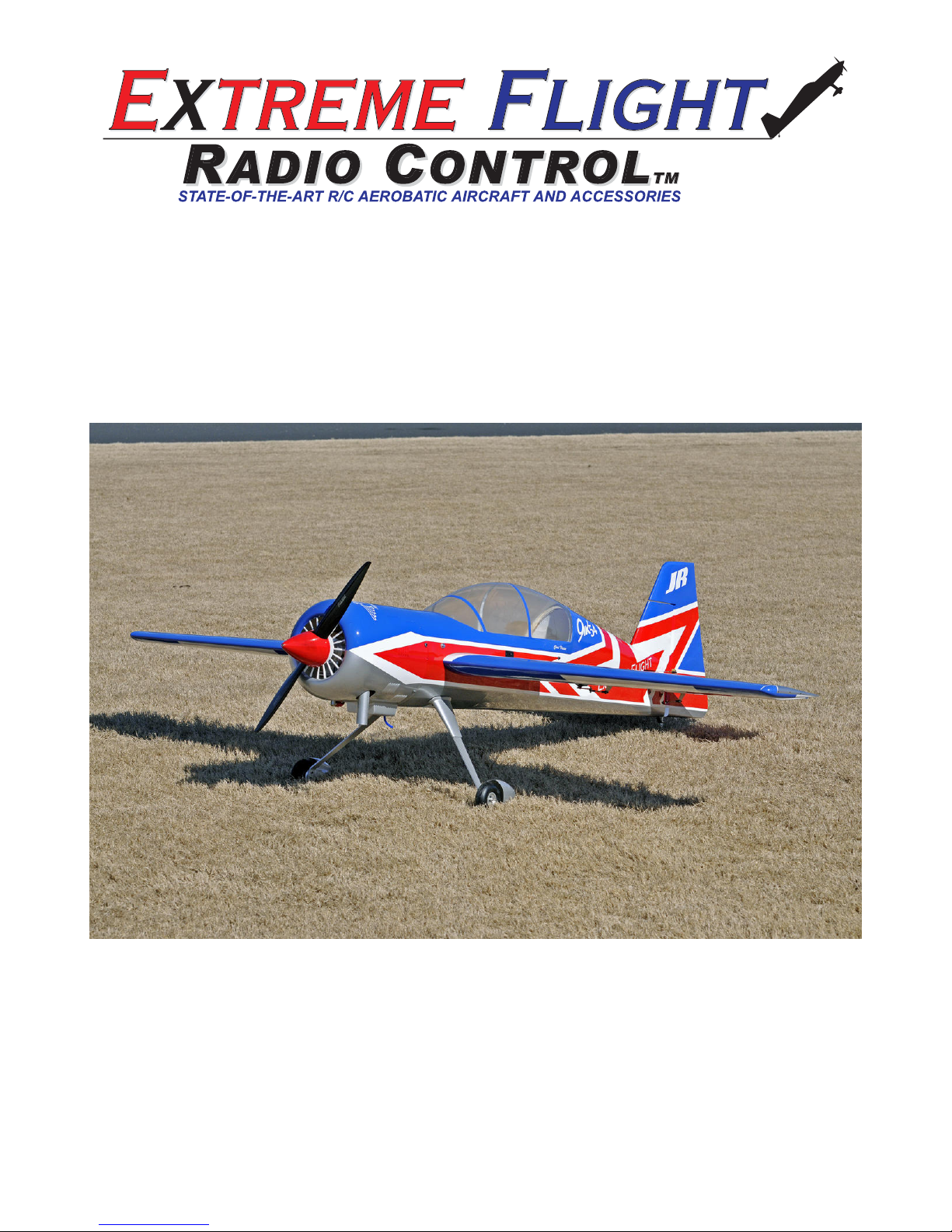
1. Locate the horizontal stabilizer/elevator assemblies as well as the composite control
horns and base plates from the elevator hardware package. Use a sharp #11 blade
or soldering iron to remove the covering over the 2 slots for the elevator control
horns on the bottom of the elevator surface.
2. Insert the 2 control horns into the base plate and trial fit the horns into the slot,
making sure they seat properly against thebase and elevator surface.
6
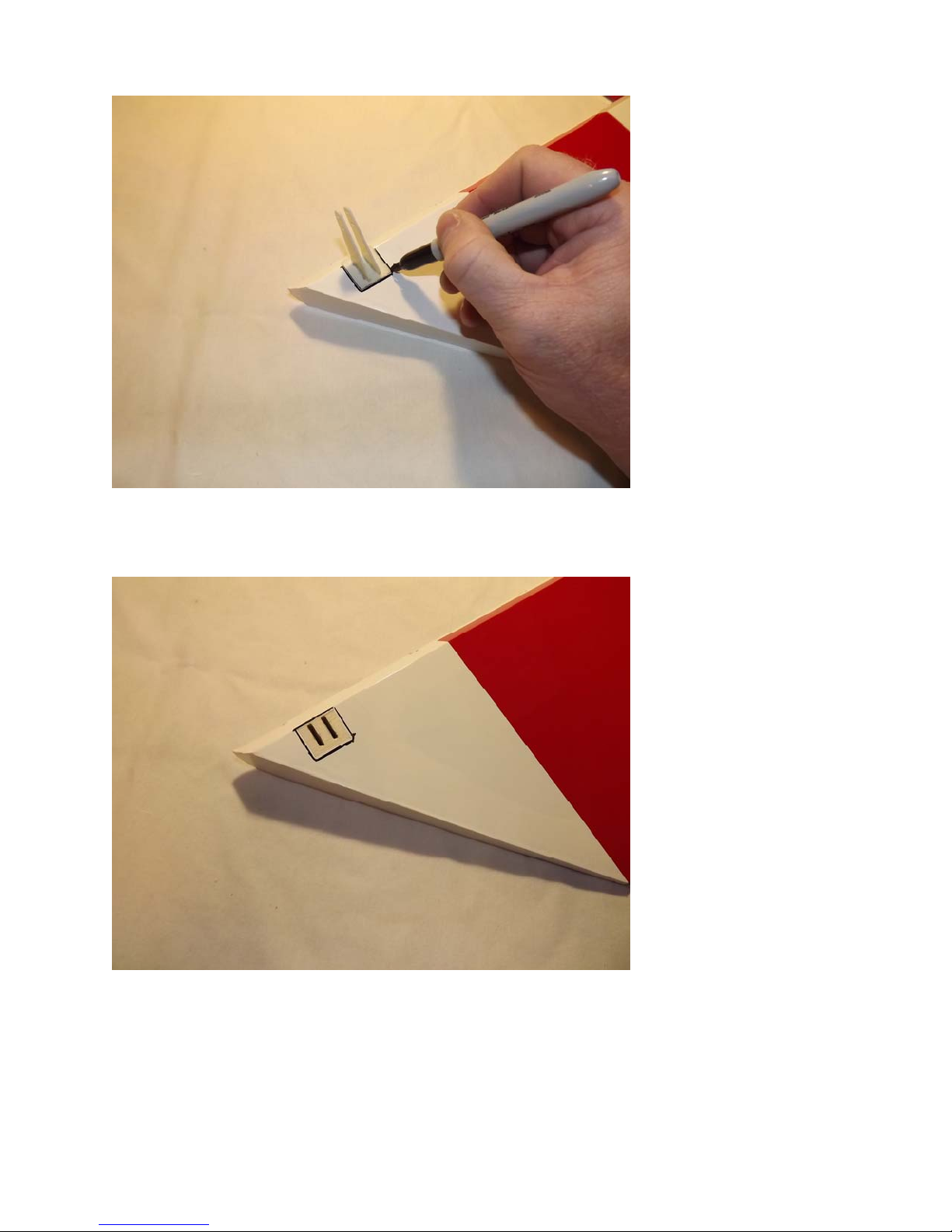
3. Trace around the base plate with a felt tipped marker.
4. Remove the horn assembly and use a #11 blade to remove the covering from inside
the ink line you traced around the control horn base.
7
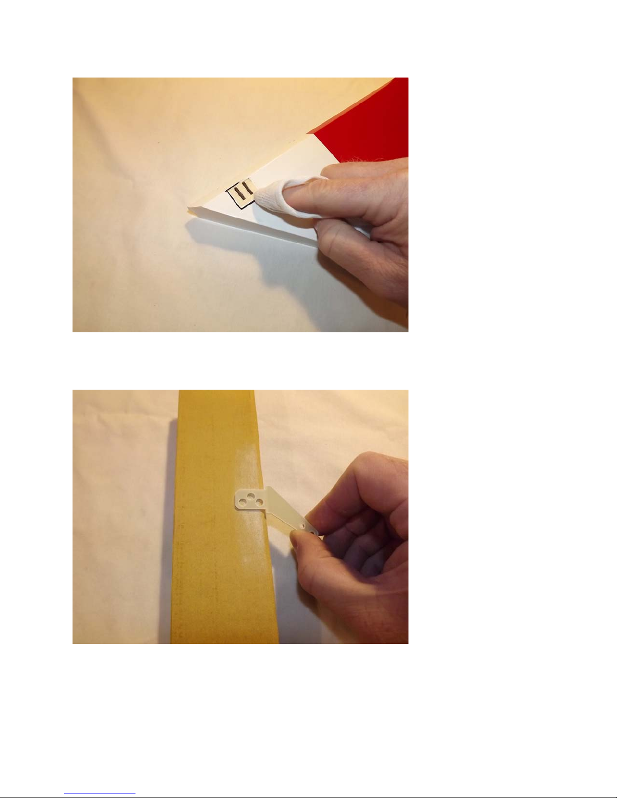
5. Wipe away the ink line with a cotton cloth or paper towel soaked in denatured
alcohol.
6. Use sandpaper to scuff the portion of the horns and base plate that will be inserted
into the elevator.
8
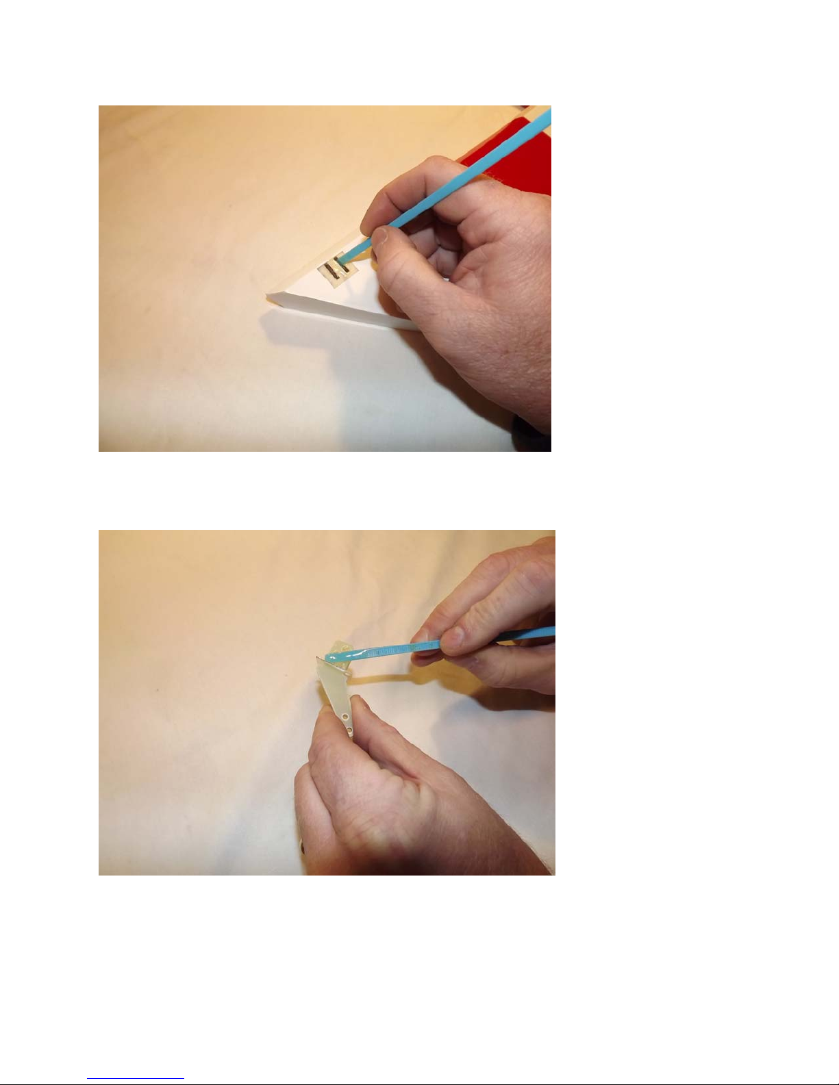
7. Apply 30 minute epoxy to the elevator slots using a zip tie to ensure the slots are
filled will epoxy.
8. Also, apply a generous amount of epoxy to the bottom of the G-10 control horns and
base plate.
9
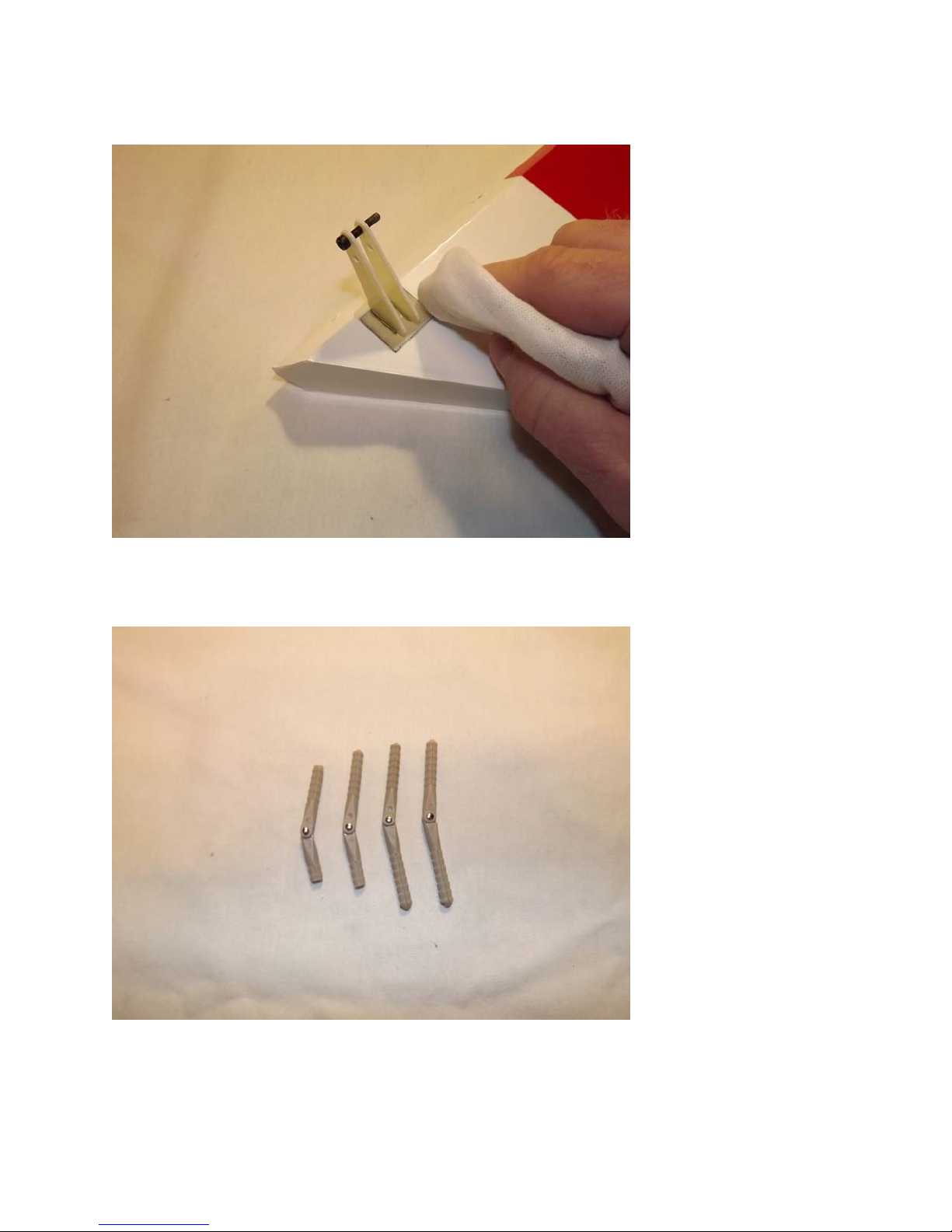
9. Reinsert the assembly into the elevator and wipe away any excess epoxy with a cloth
and denatured alcohol. Place a 3mm bolt through the horns to help insure proper
alignment and set aside to dry. Repeat for the other elevator half.
10. Next, remove the pin hinges from the horizontal stabs. Take note there are two pins
that are shorter than the others - this is to allow for clearance of the stab tube.
Note: There are several methods and adhesives that can be used for installing the
hinges. We will describe the way we do it as this method has proven itself over many
years of model building.
10
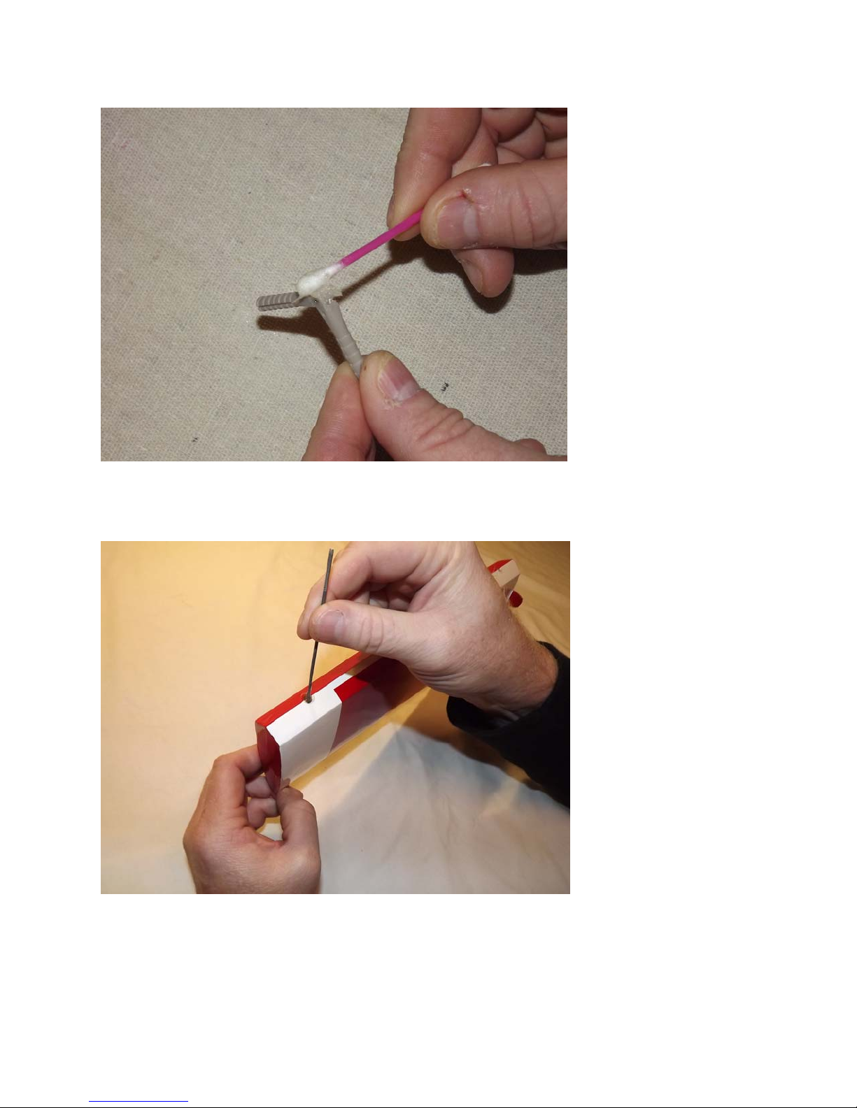
11. Use a cotton swab to apply petroleum jelly ONLY to the knuckle of the hinge. This
will keep the epoxy from getting into the hinge which can cause it to bind.
12. Mix a generous batch of 30 minute epoxy. Use a zip tie or an old pushrod to
thoroughly coat and fill the hinge holes on the stab with epoxy.
11
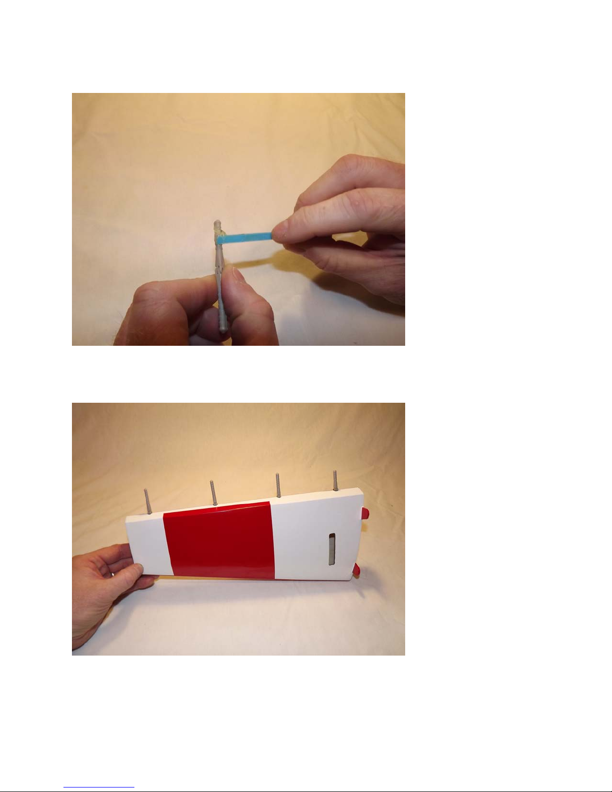
13. Next, coat one side of all 4 hinges with epoxy and push the hinges into the holes of
the horizontal stab. Remember the short hinges go in the two holes closest to the
fuse.
14. Make sure the hinge pins are centered in the hinge gap and that they pivot 90
degrees to the stab.
12
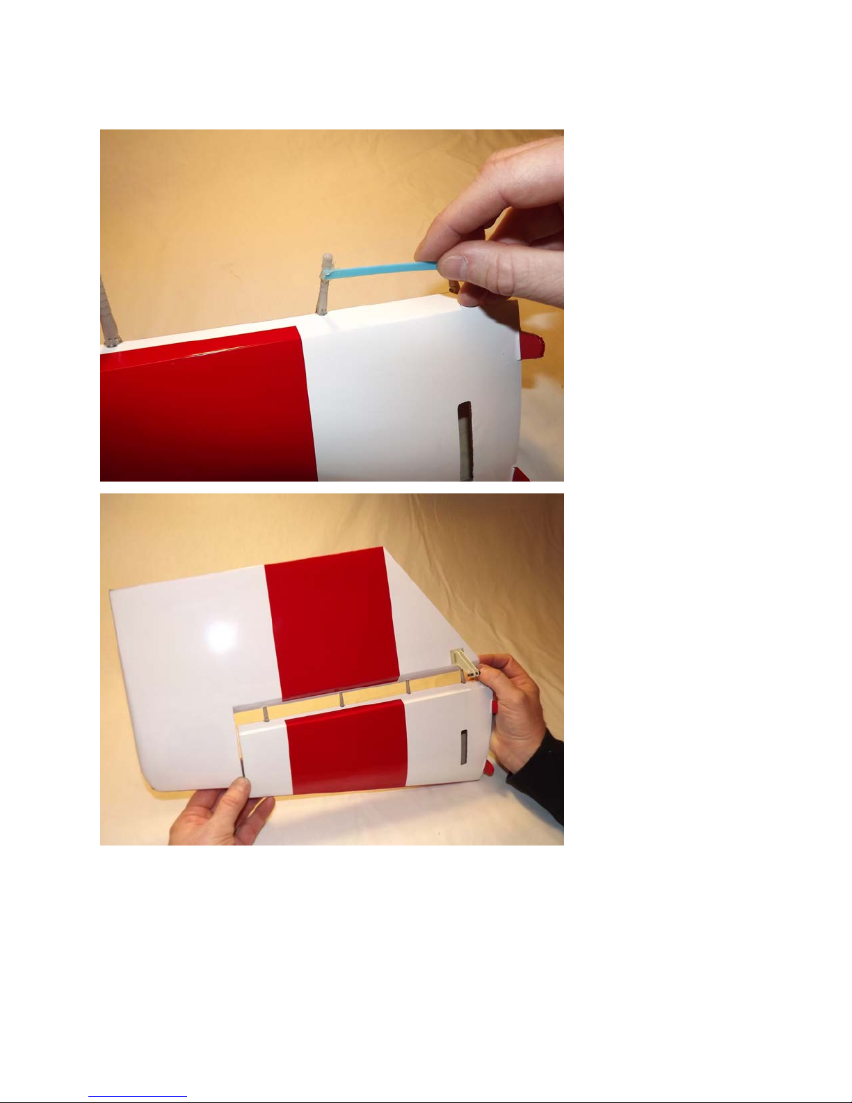
15. Now coat the other side of the hinges as well as the hinge holes in the elevator with
epoxy and install the elevator into the stab. Don’t forget to apply epoxy in the hinge
holes on the stab before installing the stab to the elevator.
13
 Loading...