


50cc Extra 300 ARF
Instruction Manual
©Copyright 2007 Extreme Flight RC, Ltd.

Please take a few moments to read this instruction manual before
beginning assembly. We have outlined a fast, clear and easy method to
assemble this aircraft and familiarizing yourself with this process will
aid in a quick, easy build.
Please read the following paragraph before beginning
assembly of your aircraft!
THIS IS NOT A TOY! Serious injury, destruction of property, or even
death may result from the misuse of this product. Extreme Flight RC is
providing you, the buyer with a very high quality model aircraft
component kit, from which you, the buyer, will assemble a flying model.
However it is beyond our control to monitor the finished aircraft you
produce. Extreme Flight RC will in no way accept or assume
responsibility or liability for damages resulting from the use of this user
assembled product. This aircraft should be flown in accordance to the
AMA safety code. It is highly recommended that you join the Academy
of Model Aeronautics in order to be properly insured, and to operate
your model at AMA sanctioned flying fields only. If you are not willing
to accept ALL liability for the use of this product, please return it to the
place of purchase immediately.
Extreme Flight RC, Ltd. guarantees this kit to be free of defects in
materials and workmanship for a period of 90 days from the date of
purchase. All warranty claims must be accompanied by the original
dated receipt. This warranty is extended to the original purchaser of
the aircraft kit only. Please inspect the model immediately upon receipt.
Extreme Flight RC in no way warranties its aircraft against flutter. We
have put these aircraft through the most grueling flight tests imaginable
and have not experienced any control surface flutter. Proper servo
selection and linkage set-up is absolutely essential. Inadequate servos or
improper linkage set up may result in flutter and possibly the complete
destruction of your aircraft. If you are not experienced in this type of
linkage set-up or have questions regarding servo choices, please contact
us. It is your responsibility to ensure the airworthiness of your model.
2

Congratulations on your purchase of the Extreme Flight RC 50cc Extra
300 ARF! Like our previous 50cc Yak-54 release, the Extra is among
the largest aircraft currently available for 50cc gas engine power. Its
light weight yet robust construction allows the Extra to perform
tournament level maneuvers on an economical 50cc power plant,
allowing you to experience the performance and stability of a much
larger aircraft at a considerable savings. The Extreme Flight Extra 300
is loaded with unique features, including all first rate hardware and
components and thorough instructions to ensure a trouble free assembly
and set-up. Weight saving components are used throughout, such as
carbon fiber wing and stab mounting tubes, aluminum landing gear,
titanium pushrods and a carbon fiber tail wheel assembly, all ensuring
the lightest, most high performance aircraft possible. You will notice
there is a box built into the bottom of the Extra’s fuselage. This is a
pipe tunnel and will accommodate most canister mufflers and tuned
pipes sold for the current makes of 50-60cc engines. Also included is a
set of protective wing and stab bags and a canopy/hatch cover to keep
your investment looking great season after season. Add to that one of
our new PILOT X series helmet head figures and a very detailed scale
instrument panel and dash!
The performance ability of the Extreme Flight RC Extra 300 is
phenomenal! This sleek, fast and agile airframe is completely unlimited
in its ability to perform the full range of full stall high alpha maneuvers
and aggressive gyroscopic tumbling maneuvers. The Extra is also a
topnotch precision aerobatic machine. It is capable of performing the
entire FAI catalog of maneuvers and it has the kind of “big plane”
presence in the air that will impress the judges. This makes the 50cc
Extra a great candidate for all classes of IMAC competition.
We have spent a great deal of time and effort to provide you, the
discriminating aerobatic enthusiast, with the highest quality, most
complete package possible. We are very proud of the end result of our
labor and wish you great success with the assembly and flying of your
Extreme Flight RC 50cc Extra 300!
3

A few tips to ensure success and airframe longevity
1. We are very pleased with the level of craftsmanship displayed by the builders
in our factory. Through many grueling test flights containing maneuvers
that no aircraft should be subjected to, our prototypes have remained rigid
and completely airworthy. However, it is impossible for us to inspect every
glue joint in the aircraft. Take a few minutes and apply some medium CA to
high stress areas such as servo mounting trays, landing gear blocks, the
intersection of the wing root rib and wing sheeting, anti rotation pins, etc. A
few minutes spent here inspecting the joints and applying glue where needed
is time well spent
2. Having survived the journey half way around the world while experiencing
several climate changes, it is not uncommon for a few wrinkles to develop in
the covering. Fear not! These are not manufacturing defects, and are easily
removed with a little bit of heat. Use a 100% cotton tee-shirt and your heat
gun and heat the covering while gently rubbing the covering onto the wood
with the t-shirt. Be careful not to use too much heat as the covering may
shrink too much and begin to lift at the edges. Take your time, and a
beautiful, paint like finish is attainable.
3. By the time the aircraft arrives at your door step it will have been handled by
a lot of people. Occasionally there are small dings or imperfections on some
of the surfaces. A neat trick to restore these imperfections to original
condition is to use a very fine tipped hypodermic needle to inject a drop of
water under the covering material and into the ding in the wood. Apply heat
to the area with a sealing iron and the imperfection will disappear. Deeper
marks may require that this process be repeated a couple of times to achieve
the desired result, but you will be surprised at how well this technique works.
4. DO NOT SKIMP ON SERVOS! These aircraft are equipped with very large
control surfaces that deflect over 45 degrees. A lot of servo power is required
to prevent flutter and to maintain the required deflection for maneuvers. We
absolutely recommend the use of high torque METAL GEAR servos. We
have had great success with the Hitec HS-5955 servos in our prototypes. We
recommend this servo or the JR 8611A or new 8711 for all flight surfaces.
5. Use a high quality epoxy for installing the composite control horns and
hinges. We highly recommend the use of Pacer Z-Poxy 30 minute formula.
We have used this glue for many years with zero failures.
4

Hardware
Your new Extreme Flight 50cc Extra 300 includes all necessary hardware with
the exception of main wheels, tailwheel, axles and collars and a 4” spinner.
These items were omitted as I have been unable to source satisfactory versions of
these items in China. I recommend Dubro 5/32” axles and collars and 3.5 inch
main wheels.
You will find a complete pull-pull system, as well as high quality heavy duty ball
links, titanium turnbuckle pushrods and composite control horns, and a carbon
fiber tailwheel assembly. You will also find 3 white ball links. 2 of these are for
use with the included 2mm pushrod for the throttle assembly (this set-up is for
the DA-50-other engines may require a longer pushrod), the other is for the
bottom of the rudder to retain the tailwheel tiller arm.
The bonded sealing washers are used when mounting the cowl and
canopy/hatch. When the bolts used to retain the canopy/hatch and cowl are
tightened against the bonded sealing washer, the rubber on the washer
compresses, preventing the bolt from backing out. The rubber on the washer
also protects the surface of the cowl. Tighten the bolts until the rubber
compresses, but do not allow the metal part of the washer to make contact with
the cowl.
For best results, remove all set screws from the tailwheel assembly and
disassemble the unit. File flat spots on the tailwheel wire so that all set screws
will seat properly. Place a drop of blue Loctite on all set screws and re-insert
them into their holes.
Graphics
The Extra is not supplied with graphics. The “sticker” type graphics included
with our smaller aircraft simply don’t hold up well to gasoline. We recommend
using vinyl graphics. There are several companies that specialize in model
aircraft logos and can supply you with a top notch graphics package that will
really dress up your Extra. Our local graphics guy Jeff Dean of Vital Signs and
Graphics (770-363-2727 or www.vital-signs.biz) has packages available for the
Extra like the ones pictured on our aircraft. He can modify these to suite your
needs as well.
5
Elevator Assembly
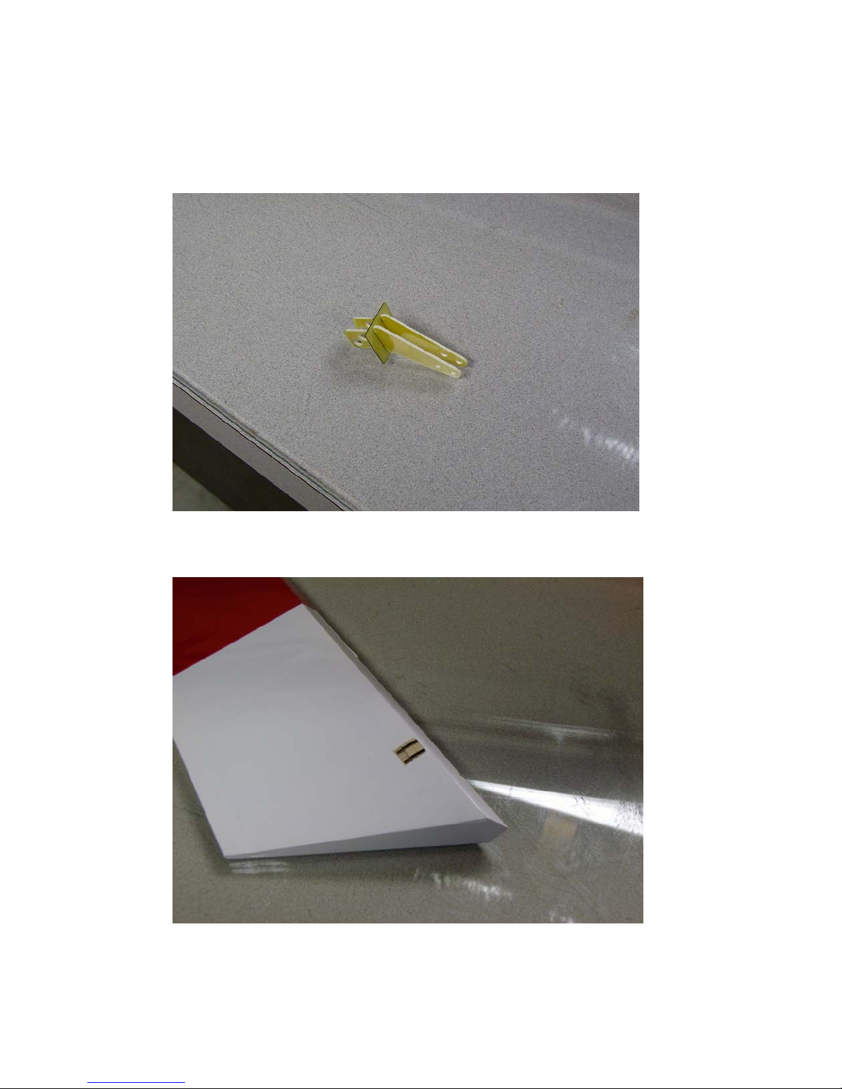
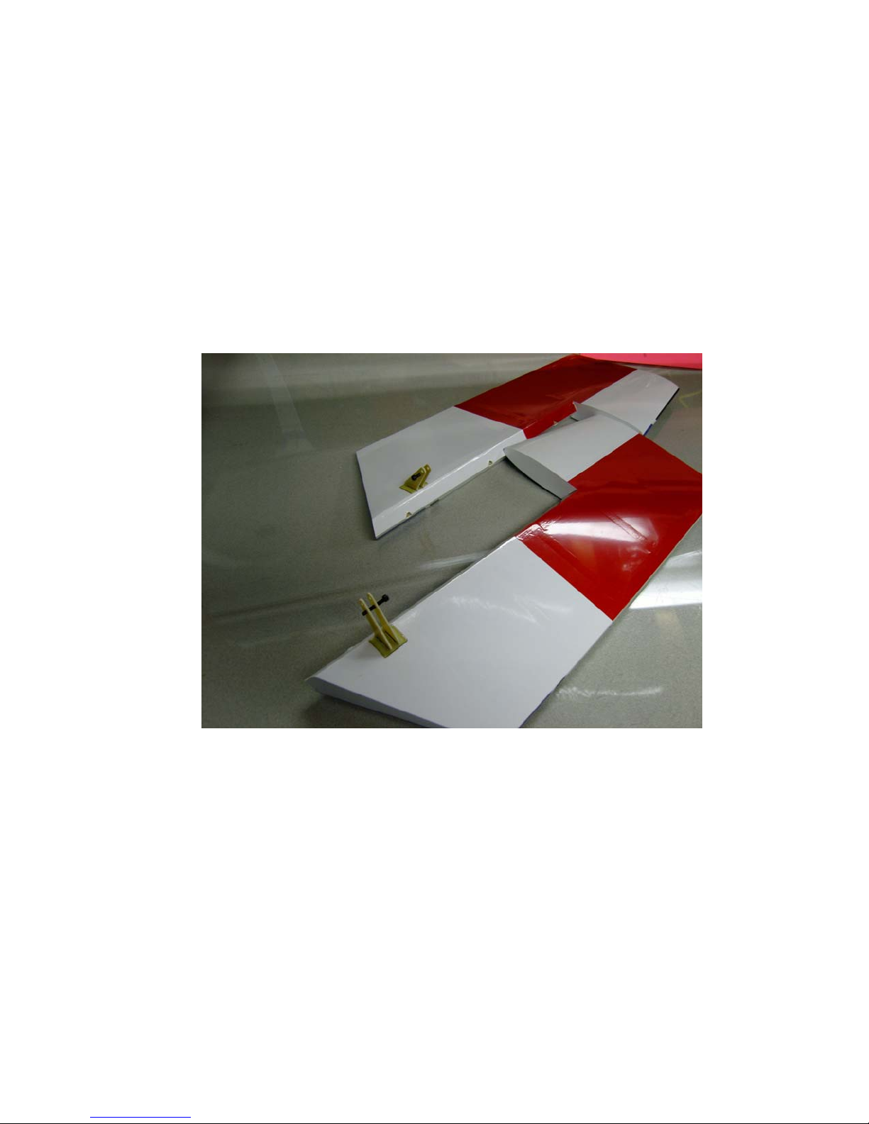
1. Locate the horizontal stabilizer/elevator assemblies as well as the
composite control horns and base pieces from the elevator hardware
package.
2. Use a sharp #11 blade to remove the covering over the pre-cut control
horn slots near the bottom leading edge of the elevator. Cut the
covering 1/16” from the ends and sides of the slots.
6
3. Insert the 2 control horns into the base plate and trial fit the
horns into the slot and make sure they seat properly against the
base and elevator surface. You may need to remove 1/16” from the
front of the base plate to prevent it from overhanging the bevel.
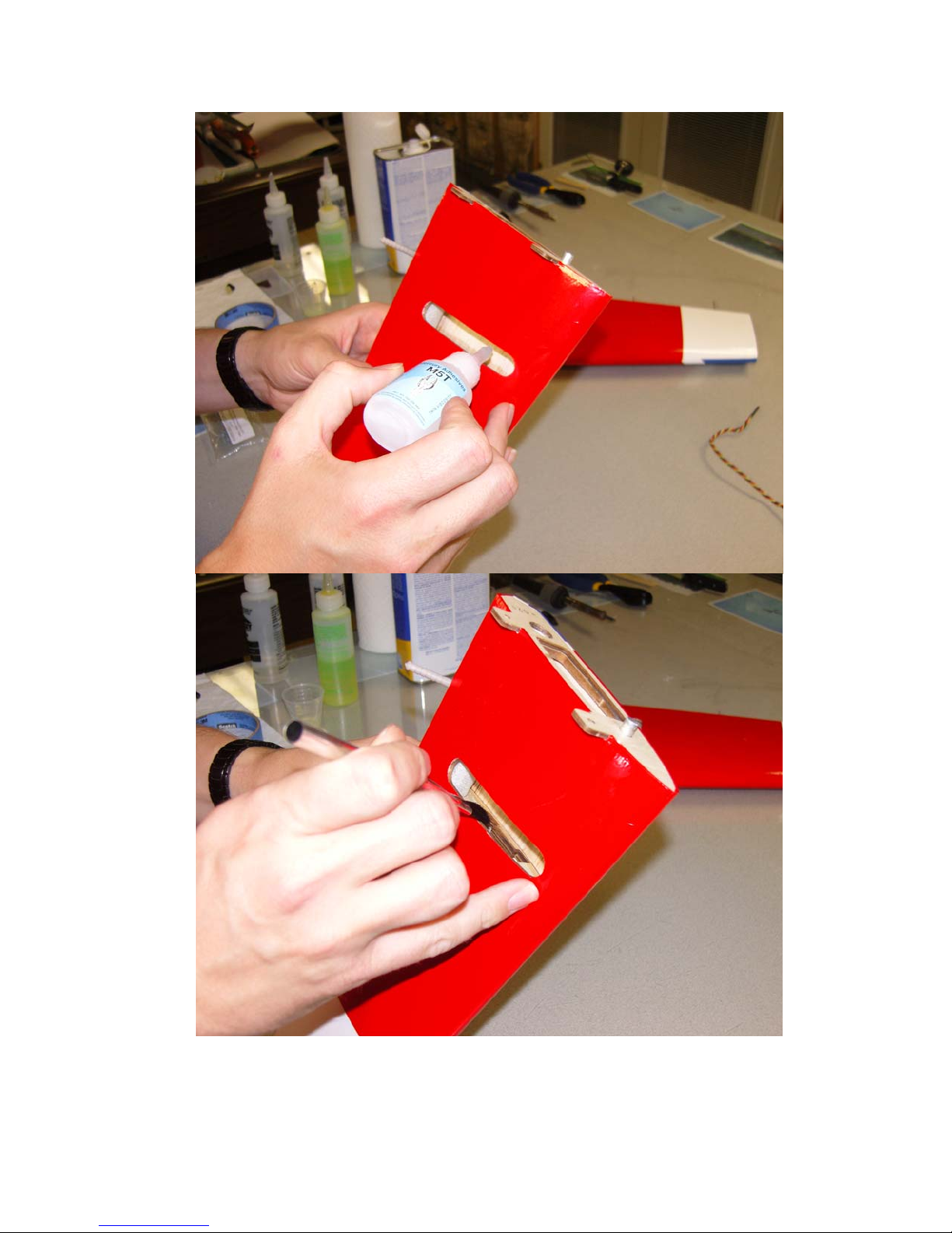
Remove the horn assembly and scuff the portion of the horns that
will be inserted into the elevator with sandpaper. Apply 30 minute
epoxy to the slots and thoroughly coat the horns and base plate
bottom. Reinsert the assembly into the elevator and wipe away
any excess epoxy with a paper towel and denatured alcohol. Place
a 3mm bolt through the horns to help insure proper alignment and
set aside to dry. Repeat for the other elevator half.
7
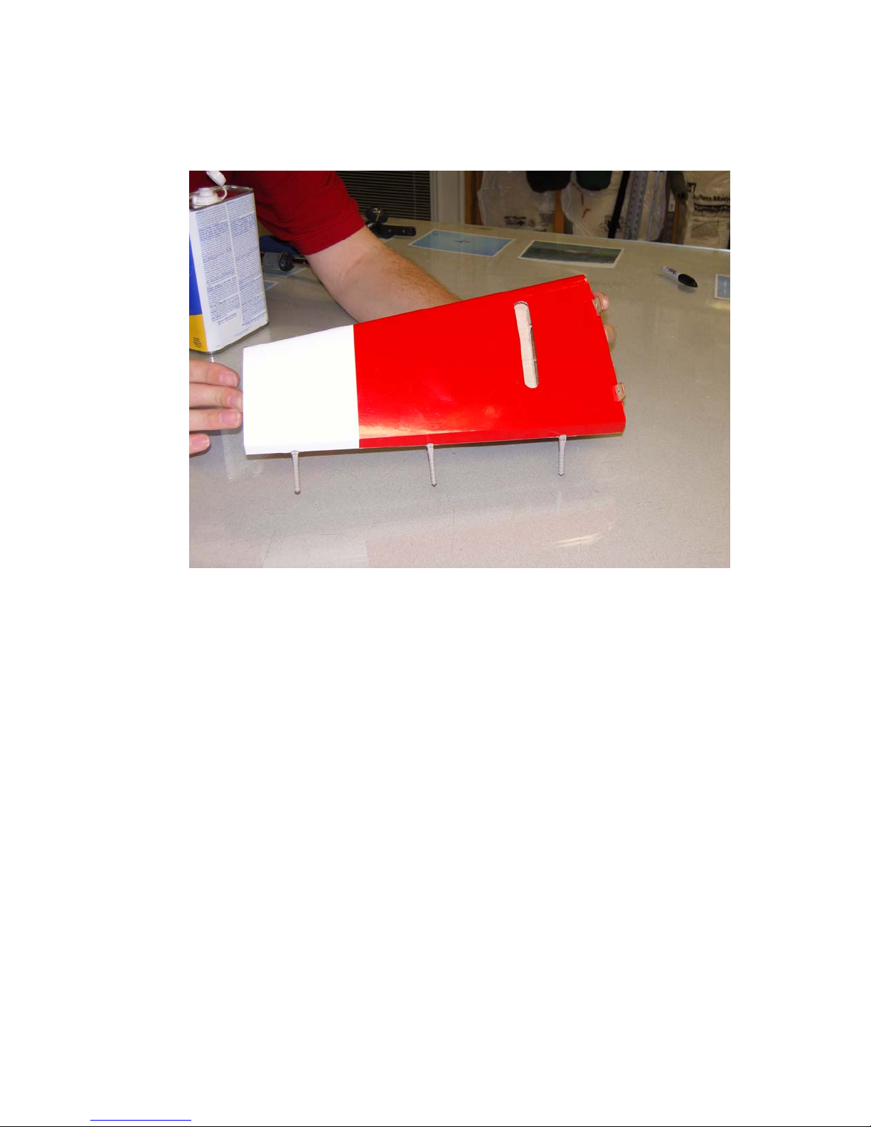
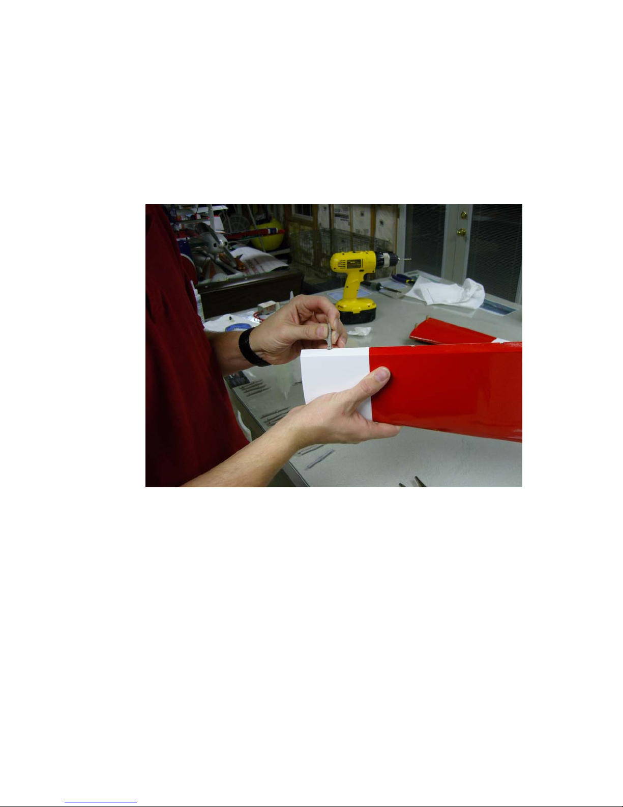
4. Use a sharp #11 blade to remove the covering from the slot for the
elevator servo control horn. You may have to slightly enlarge this
hole to allow for maximum travel.
5. Before installing the elevator servos, I highly recommend that you
take a moment and wick some thin CA (I prefer the Mercury
Adhesives line of CAs) around the servo mounting rib and root rib
where they attach to the sheeting as well as the anti-rotation pin
where it is mounted in the stab. Temporarily install the servo arms
and electronically center the servos. It will be much easier to
match up the servos at this point than when they are installed. I
also recommend that you thin a small amount of epoxy with a few
drops of alcohol and apply a light coat to the inside of the stab and
to the servo mounting rib as well as to the root rib and mounting
tabs. Over time exhaust residue begins to collect here and by
sealing it with epoxy you will prevent degradation of the wood.
8
9
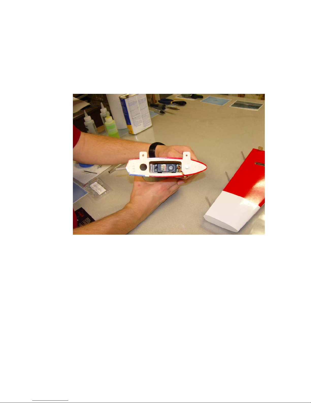
6. Use the manufacturer supplied mounting hardware and install the
elevator servo with the output shaft toward the front of the stab.
Feed the servo wire out of the hole in front of the servo and out of
the root rib. You will need to attach a 36” servo extension to the
servo lead to reach the receiver in the radio compartment. If you
intend to remove your stabs for transport you will need a longer
extension or additional extensions.
7. In this step I will outline the procedure we use to install the hinges.
There are several ways to do this and several adhesives you can
use. We will describe the way we do it, as this method has proven
itself over many years of model building. If you are new to this
type of hinging process then I recommend that you install a single
hinge first just to acquaint yourself with this method. Before
starting the process get a few items together that will aid you as
you proceed. You will need the following items: 30 minute epoxy
(again, we recommend Pacer Z-Poxy), a scrap piece of pushrod or
1/8” dowel, paper towels and denatured alcohol. Locate 3 hinges
per elevator half. You will need to cut 1 hinge just beyond the
second knuckle to clear the fiberglass tube socket in the stabilizer.
Insert the carbon fiber wing tube into the socket while testing for
proper hinge length to avoid damaging the fiberglass sleeve. Mix a
generous batch of 30 minute epoxy. Use the pushrod or dowel to
thoroughly coat and fill the hinge hole with epoxy, then coat the
hinge with epoxy. Push the hinge into its hole until the joint is
10
about a ¼” from its final position and use a paper towel to remove
the excess epoxy that has been forced from the hole. Push the
hinge the rest of the way in and make sure the hinge pin is centered
in the hinge line. Use some denatured alcohol and a paper towel to
remove all excess epoxy, especially on the hinge pin. When you
are satisfied with the result set the surface aside to dry. Position
the drying piece so that any excess epoxy will pool around the rear
of the hinge.
8. When you are comfortable with this process you should be able to
do one side of a surface per batch of epoxy. Glue all hinges into
the stabilizer first. After the glue has set trial fit the elevator to the
stab and adjust if necessary. There should be as little gap as
possible between the stab and elevator. When satisfied with the fit
remove the elevator and repeat the gluing process outlined above.
Be sure to wipe away all excess epoxy! Set aside to dry. Repeat
this process for the other stab/elevator half.
9. After the hinges have dried thoroughly, pull on them to make sure
they are properly installed. The hinges will probably feel a little
stiff as it is almost impossible to get all of the glue out of the joint.
Use a fine tipped hypodermic needle and place one (only one!)
drop of acetone on each side of the hinge pin. Move the elevator
back and forth a few times and you will feel it loosen up.
Be careful to only use one drop as you don’t want to weaken
the glue joint! Add a drop of penetrating oil to each hinge pin and
11
you will ensure a smooth operating surface with no binding. Seal
the bottom of the hinge gap with a strip of Ultracote or Blenderm
tape. Be sure to fully deflect the control surface when applying the
tape or Ultracote to allow full deflection once the gap is sealed.
10. Thread 2 of the heavy duty ball links onto one of the titanium
pushrods. Remember that the ends of the pushrods are reverse
threaded so that they can be adjusted like a turnbuckle without
removing the linkage. Insert a 3mm socket head cap screw into the
ball link and into the servo arm. If using the SWB arms you will
need to drill out the hole to accept the 3mm bolt. Secure with a
3mm nylon insert locknut.
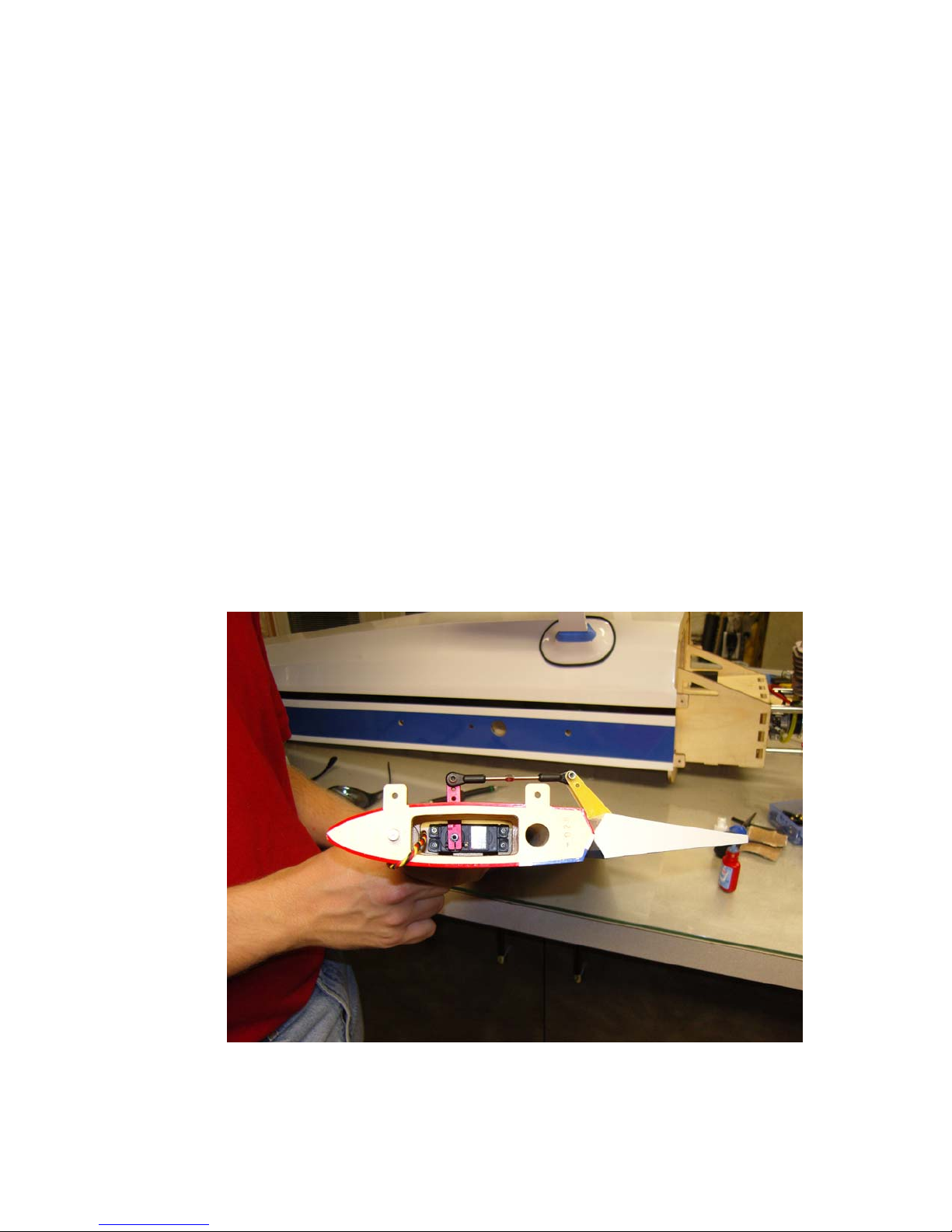
11. Place the servo arm onto the servo (which you should have
electronically centered in a previous step) and make sure the
elevator is in the neutral position. Adjust the ball links until the
linkage fits between the composite control horns and lines up with
the pre-drilled top hole. Insert a 3mm socket cap screw into a
washer, through one side of the composite control horn, through
the ball link, and finally through the other composite control horn.
Secure with a 3mm nylon insert lock nut. Use blue Loctite on all
bolts! See finished set-up below.
12. As mentioned previously, you may need to adjust the size of the
servo arm exit slot to achieve maximum travel. A ¼” Drum sander
in a moto-tool makes quick work of this. Repeat these steps for the
other stab/elevator half. Before you set aside the stabs take a
12
 Loading...