

Page 1

48" EPP Extra
Electric ARF Assembly Manual
Greetings and congratulations on your purchase of the 3DHS 48 EPP Extra
330SC!
Copyright 2015 EXTREME FLIGHT
1
Page 2
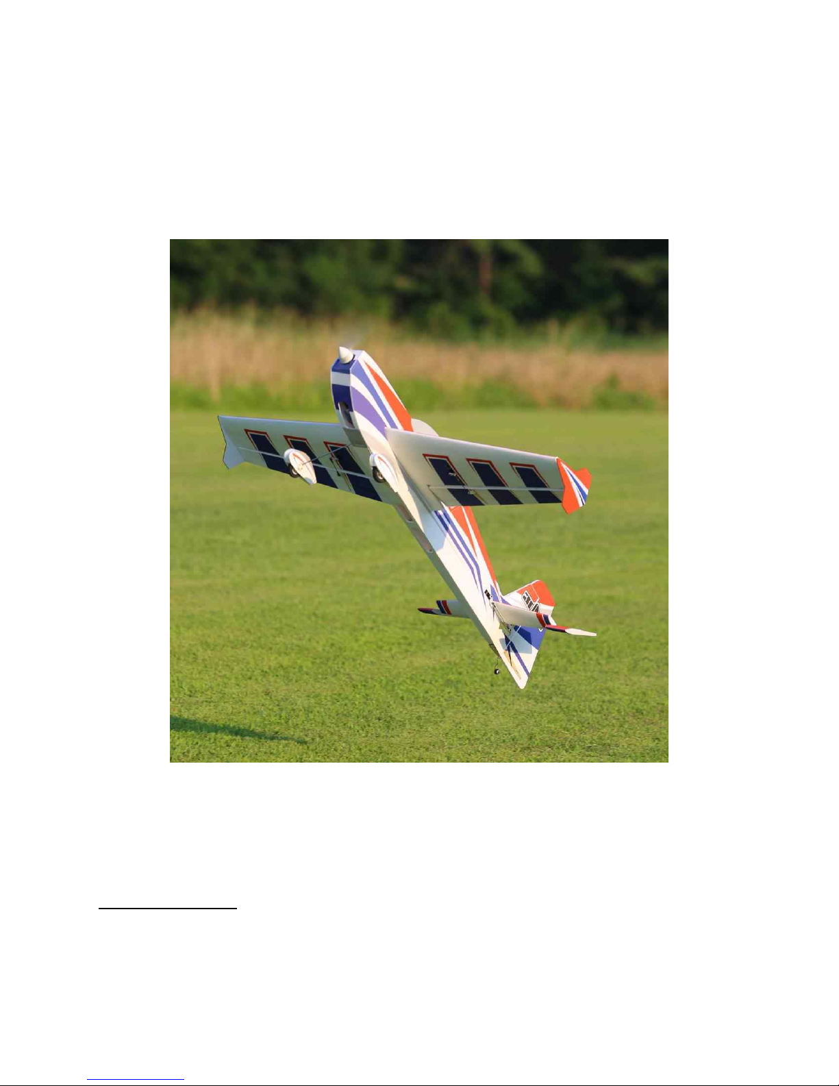
The 48" EPP Extra combines the best of the worlds of balsa and EPP foam!
Utilizing a new foam formulation, the 48" Extra brings new stiffness and
precision to this class of aircraft, and enhances the legendary durability of
EPP construction. This airplane will become your go-to practice plane for
down-low maneuvers and is a great low-stress 3D parkflyer.
Tips for Success:
1. Before starting assembly, take a few minutes to read the entire instruction
manual to familiarize yourself with the assembly process.
2
Page 3

2. Use a fresh bottle of thin CA with a fine glue tip when attaching the CA
hinges. This will ensure that the proper amount of CA wicks into the hinge
and surrounding balsa wood and creates a proper bond between the wood and
hinges.
3. Take the time to properly balance and trim your aircraft and set up rates
and exponential values. Your flying experience will be greatly enhanced by
doing this.
Items needed for completion
-Hobby knife with #11 blades
-Thin and Medium CA.
-Blue Loctite.
-Small flat head and Phillips head screw drivers.
-Standard and needle nose pliers.
-Metric balldriver or allen key set.
-4 sub micro metal geared servos. All flight testing was performed with Hitec HS-65MG
and HS-5065MG digital servos and we strongly recommend the use of either of these high
quality servos.
-Torque 2814T/820 Brushless Outrunner motor.
-Airboss Elite 45 Amp ESC.
-4S 2100-2350 mah LiPo battery.
-APC 12x6 E prop (NOT the slow fly version!).
-40 mm Extreme Flight spinner.
-2 18"-24" extensions for the elevator and rudder servos and 2 6"-8" extensions to go
between the receiver and the aileron servo leads. We recommend the 28 or 32 AWG
extensions to save weight.
3
Page 4
-Adhesive backed Velcro and Velcro strap for battery retention.
Let's begin!
1. Locate the 2 wing panels with ailerons as well as the 2 G10 aileron control
horns.
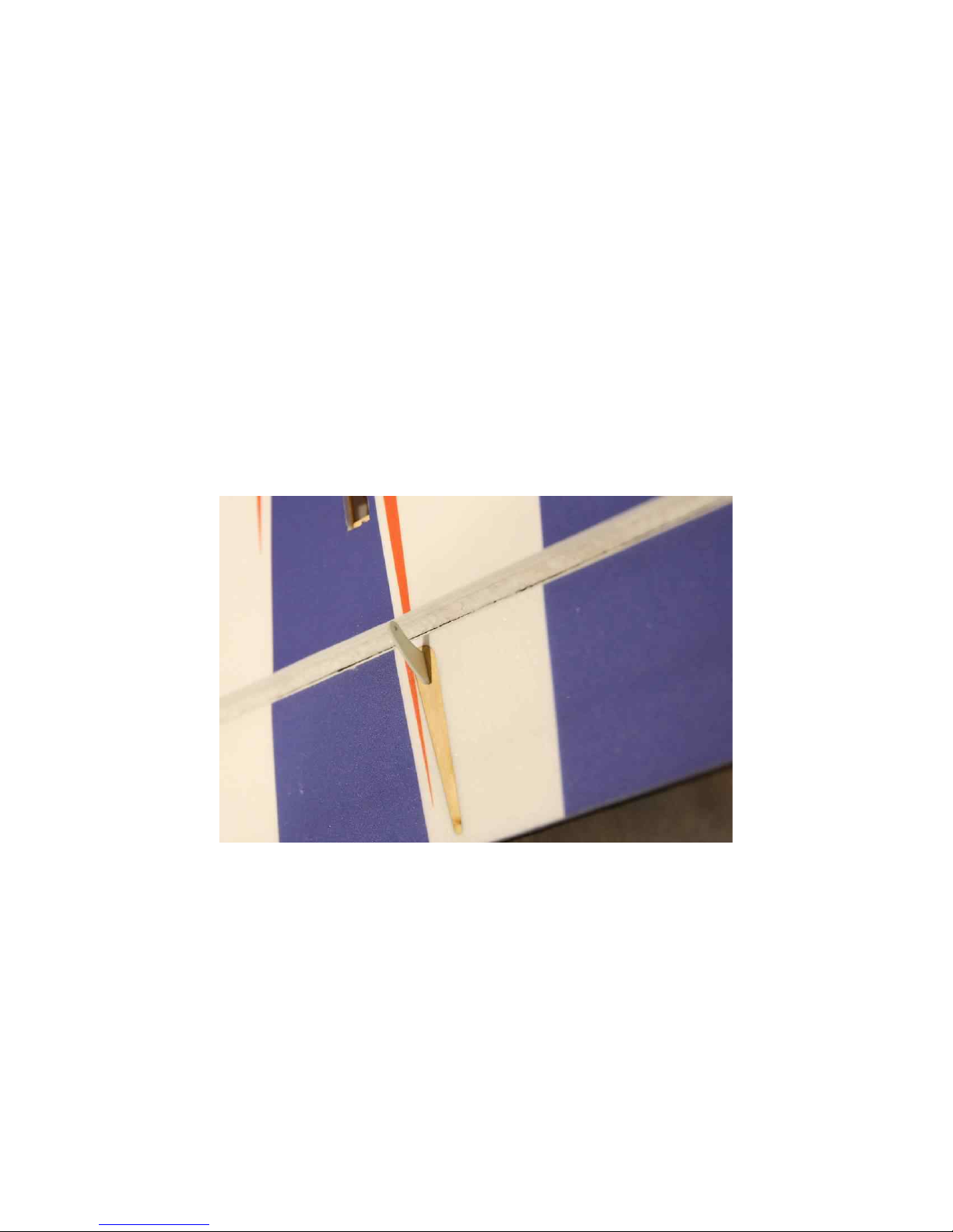
2. Scuff the portion of the control horn that will be glued into the aileron with
sandpaper. Use a glue tip on your bottle of medium CA and apply glue to the
slot as well as to both sides of the control horn. Insert the control horn into
the slot and make sure it seats properly against the surface of the aileron.
3. Install the servo using the manufacturer supplied mounting hardware with
the output spline toward the trailing edge of the wing.
4
Page 5
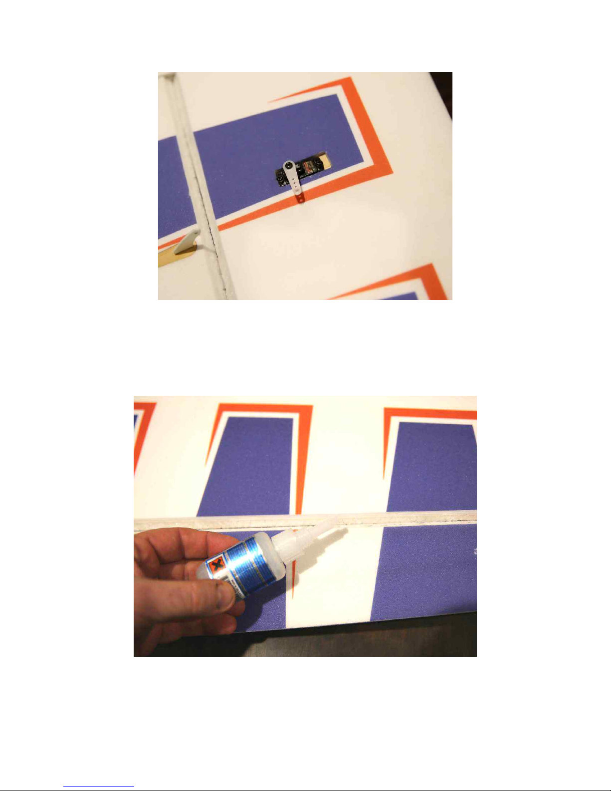
4. Slide the aileron into position on the hinges and secure with several drops
of fresh thin CA. This process is much easier and more effective if a fine glue
tip is used. Make sure to deflect the surface back and forth while applying the
CA.
5. Locate the 2 threaded pushrods that are the same length and 4 micro ball
links along with 4 2mm bolts, nuts and washers. Thread the ball links onto
5
Page 6
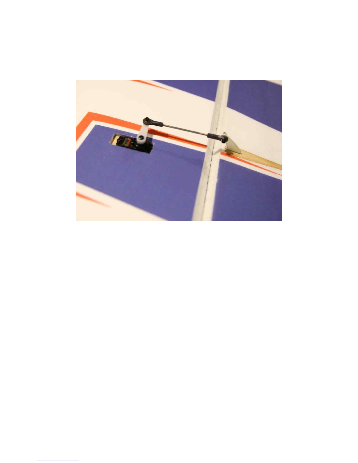
each end of the pushrods and secure to the servo arm and control horn with
the 2 mm hardware as shown in the picture. Use the longest arm provided
with your servo.
6. Repeat this process for the other wing half.
7. Locate the wire landing gear. Insert it into the open slot in the bottom of
the fuselage. Locate the wooden landing gear lock, insert it into the slot as
shown. Lock in place with a drop of thin CA.
6
Page 7
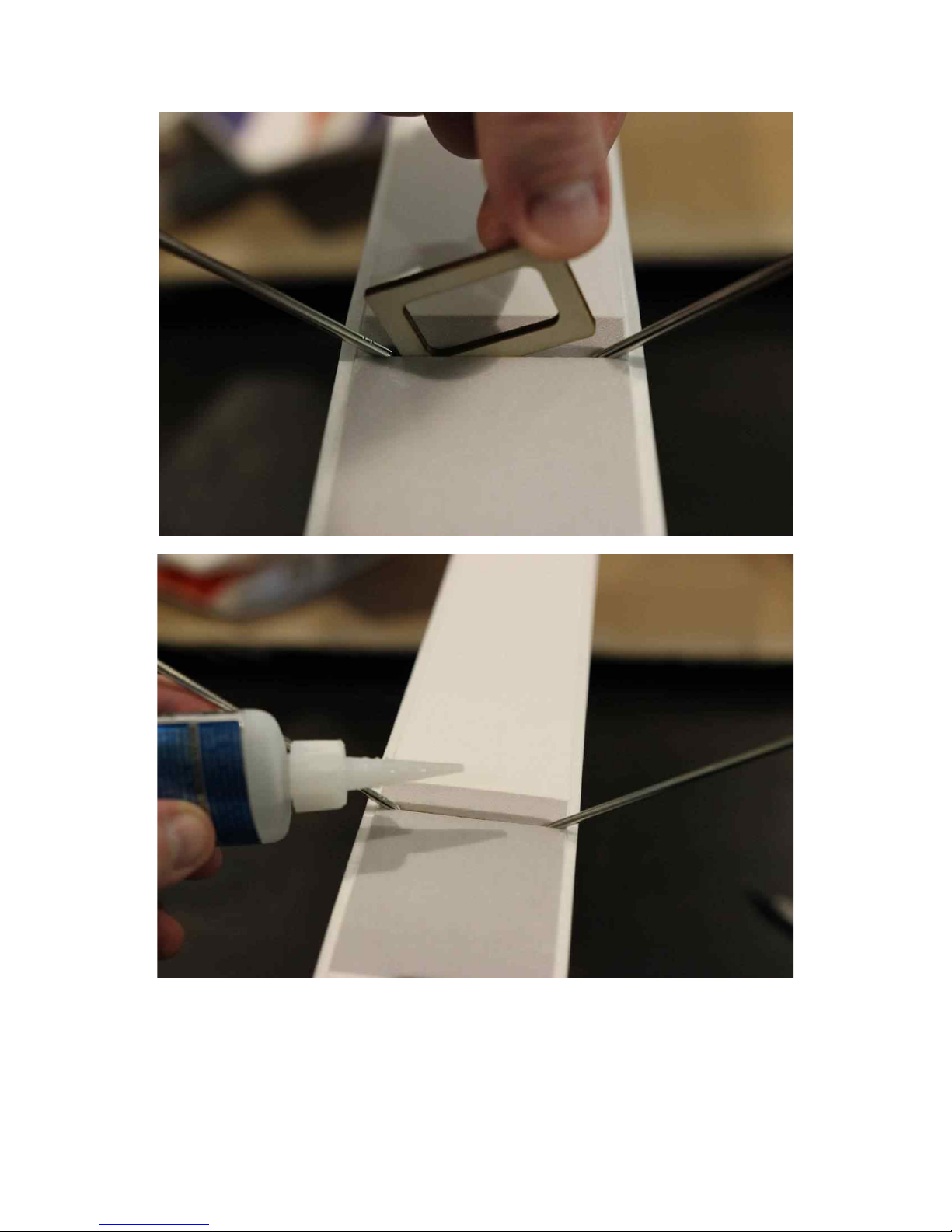
8. Install the wheel pants, spacers, wheels and wheel collars as shown.
7
Page 8
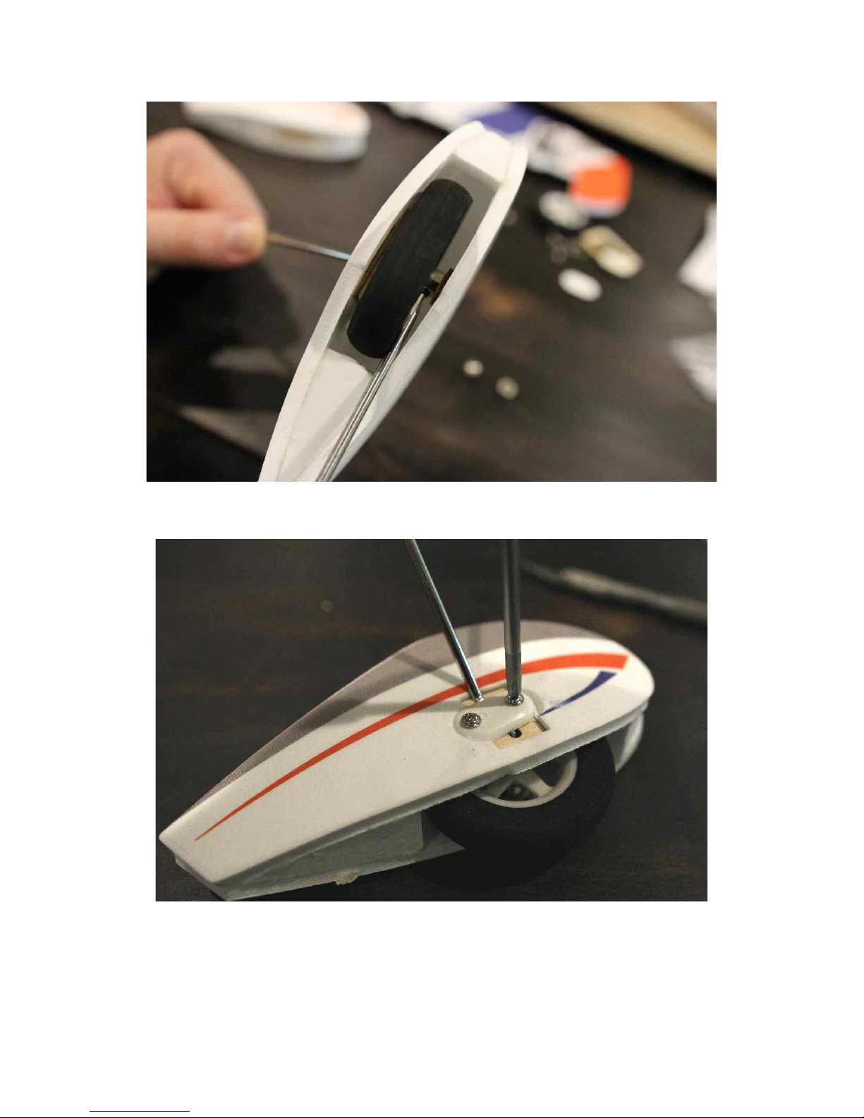
9. Install plastic retaining strap to secure wheel pant as shown.
10. Locate tail wheel wire, tail wheel bracket, tail wheel, and tail wheel collar.
Assemble as shown.
8
Page 9
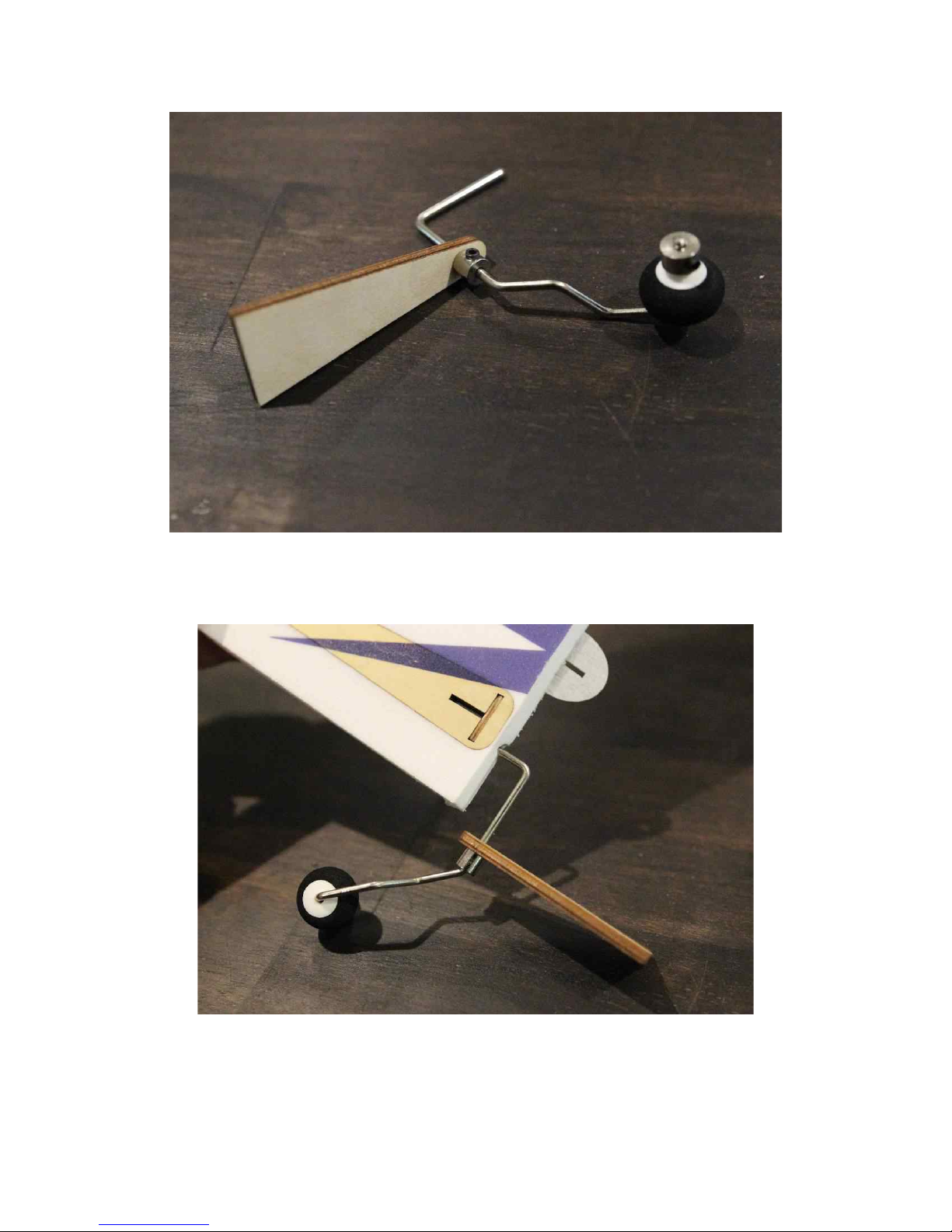
11. Locate rudder. Insert tail wheel wire into rudder as shown until it is fully
seated.
12. Insert rudder into fuselage, glue hinges with thin CA.
9
Page 10
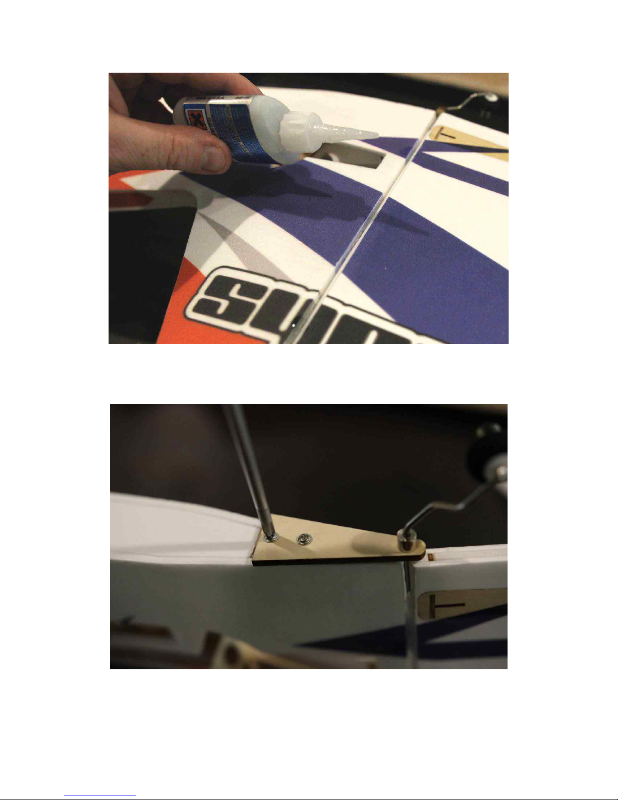
13. Attach tailwheel bracket with wood screws as shown, making sure the
rudder swings easily.
10
Page 11
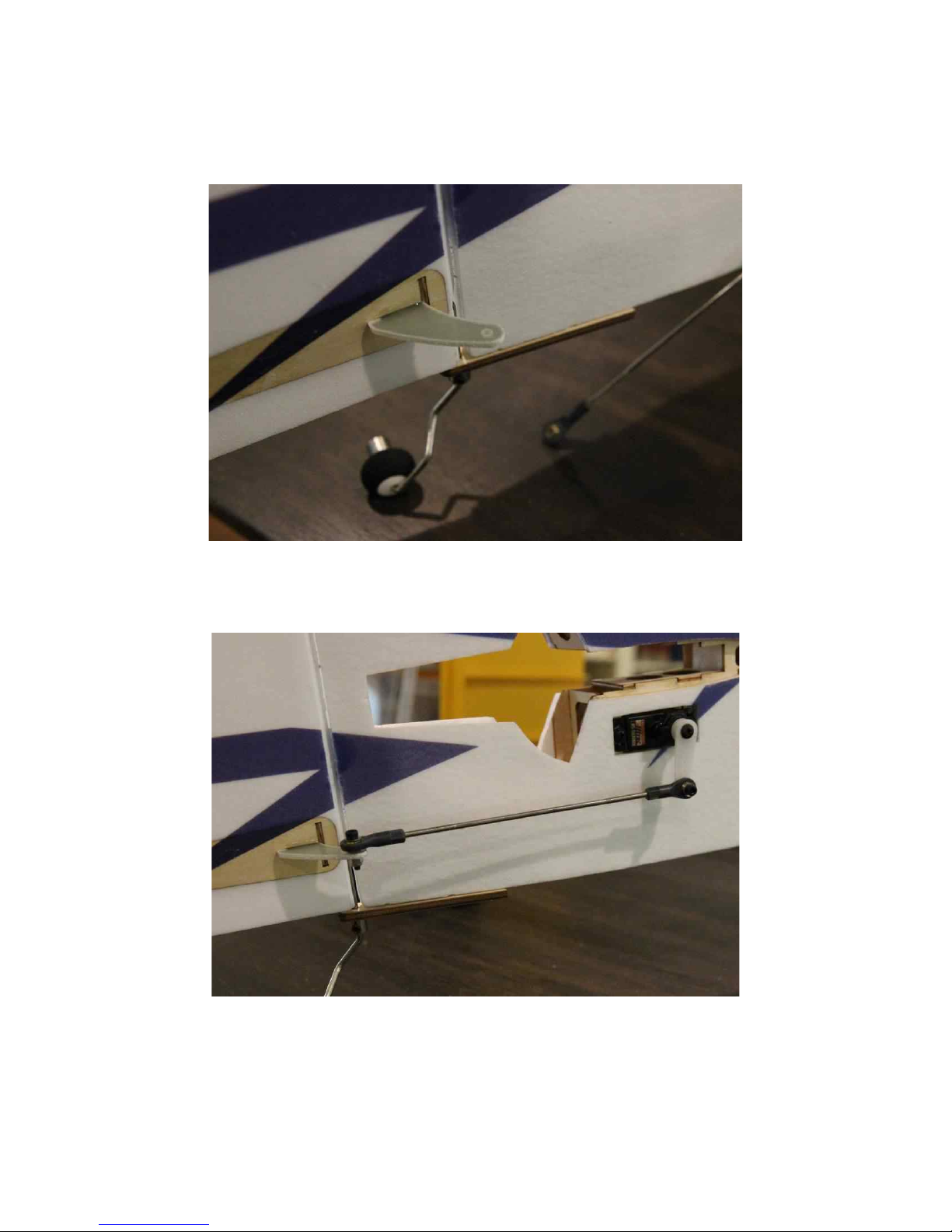
14. Install rudder control horn with medium CA as previously on aileron
horns.
15. Install servo and linkage as shown, using hardware as previously on
ailerons. NOTE: install servo wire extension on rudder servo with a lock.
16. Locate the stabilizer and elevator, separate them, and install the elevator
through the slot in the fuselage as shown. Note that you will need to orient the
11
Page 12
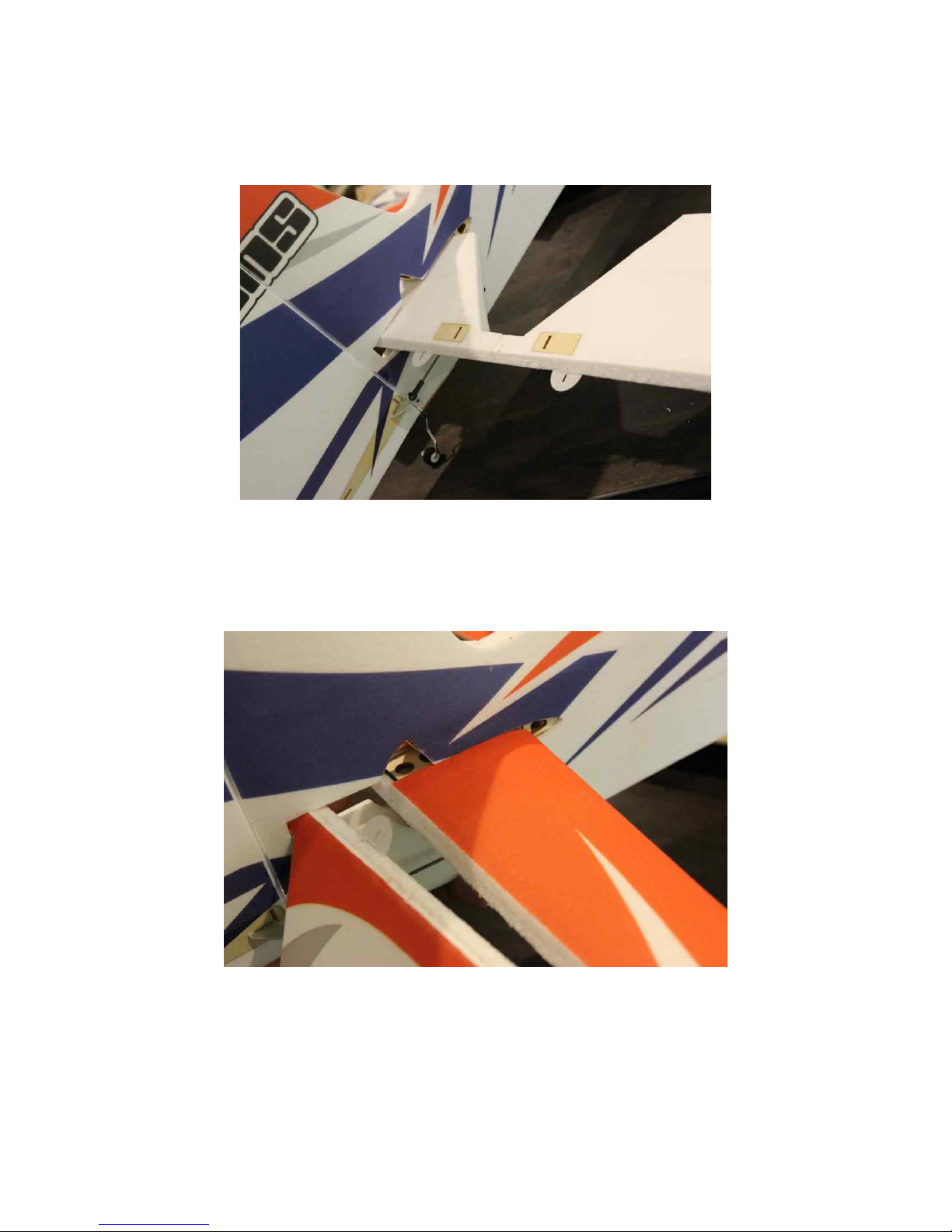
elevator upside-down and backwards when inserting and then flip it right way
around after it's installed.
17. Insert the elevator into the slot and slide forward into place. Once fully
seated in place, attach with a few drops of thin CA.
18. Install elevator onto horizontal stabilizer and use thin CA to attach hinges.
12
Page 13
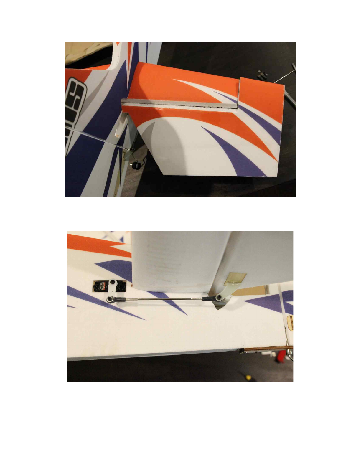
19. Install elevator control horn, servo, and linkage as shown. Note: Install
servo wire extension with a lock.
20. Insert brushless motor with mount into nose of aircraft and line up with
mounting holes. Insert 3mm mounting screws and tighten as shown. NOTE:
We highly recommend the Torque 2814-820 motor and AirBoss 45A ESC.
13
Page 14
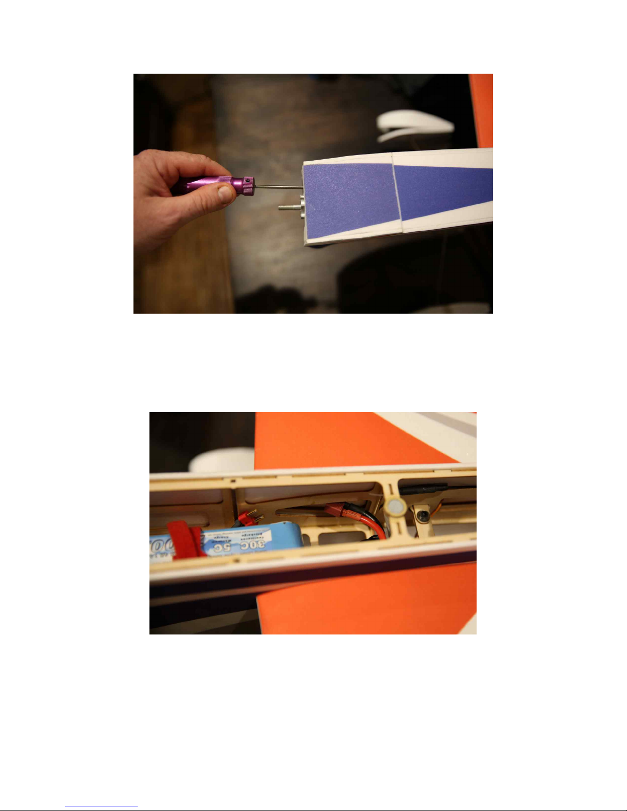
21. Mount the ESC under the battery tray with Velcro. Use adhesive Velcro
and a Velcro strap to mount the battery as shown. Slide the wings onto the
carbon wing tube and attach with screws as shown. NOTE: The carbon wing
tube is NOT glued in place, it and the wings remain removable.
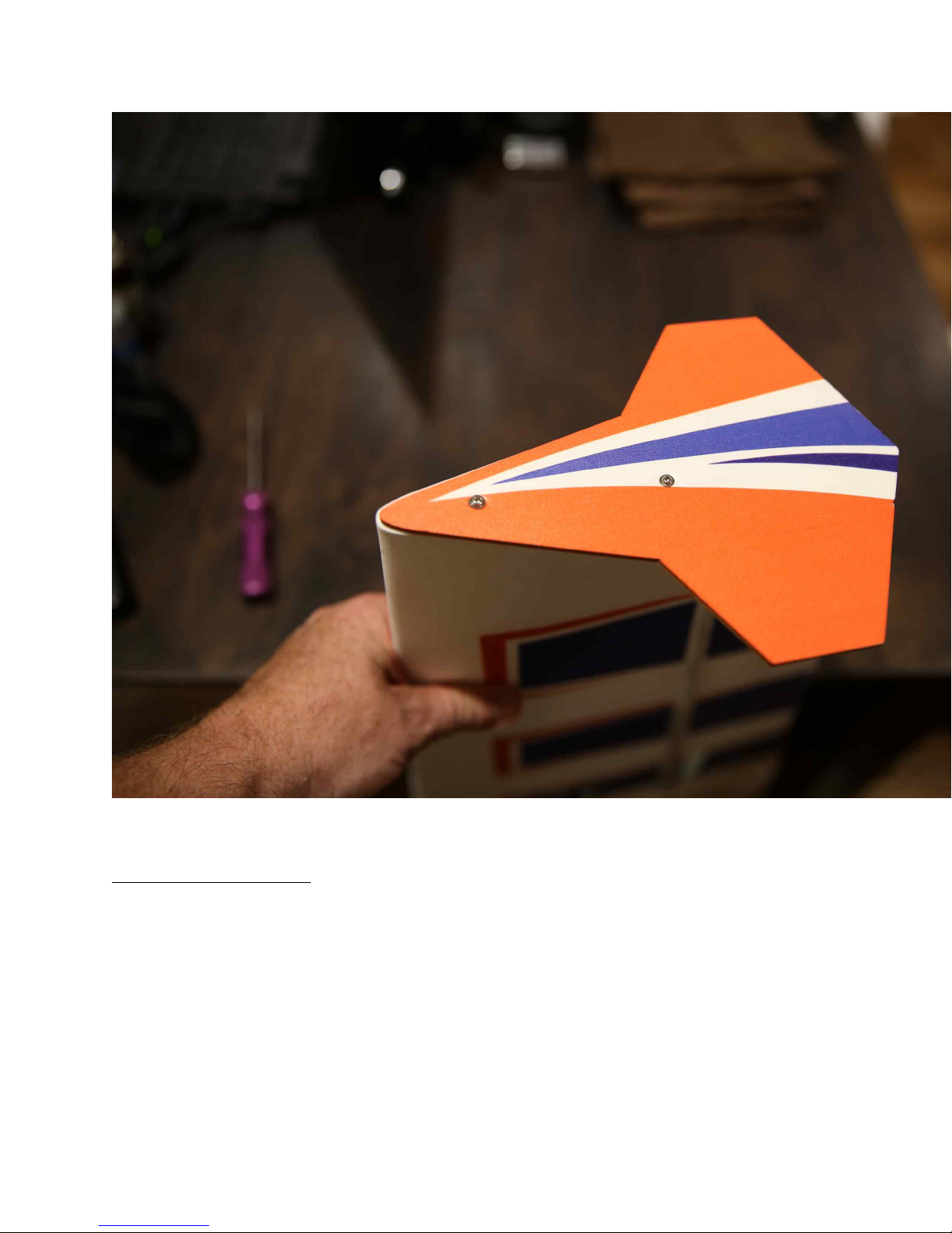
22. If using the included Side Force Generators now is the time to mount
them. Each SFG mounts using 2 wood screws.
14
Page 15
Set-up and flying tips
The CG for the Extra is on the wing tube. There is plenty of room on the
battery tray to move your battery to achieve this CG location. Depending on
your flying style you can adjust the position of the battery to alter the CG to
accommodate your preferences. For this type of aircraft where I am going to
predominantly fly aggressive 3D I typically set the airplane up with a neutral
CG, meaning that when the aircraft is flown inverted straight and level it
requires no down elevator to maintain altitude. If your flying style leans more
15
Page 16

toward precision aerobatics then I recommend setting your CG using the 45
degree line test. Fly the aircraft from left to right or right to left, whichever
direction you are more comfortable with at 3/4 to full throttle. Pull the
aircraft to a 45 degree up line and establish this line and immediately roll the
aircraft inverted. Establish this line and let go of the elevator stick. Ideally
the aircraft will continue to track on that 45 degree line for several hundred
feet before slowly starting to level off. Adjust the position of your battery to
achieve this flight condition. Once satisfied with the location of your CG
scribe a mark on the battery tray so that you can position the battery in the
same location each flight and achieve the same feel and flight characteristics
each flight.
I also highly recommend taking the time to properly set up your rates and
exponential settings. Setting up low rates for precision maneuvers and high
rates for aggressive aerobatics and 3D flight will allow you to experience the
best attributes of the Extra or any aircraft for that matter
Here are some suggested rates to get started with. These are the rates and
exponential values I feel comfortable with. They may feel awkward to you
and if so please adjust to your taste.
Elevator: Low rate-8-10 degrees; 15-20% Exponential
3D rate-45-50 degrees; 50-70% Exponential
Rudder: Low rate-20 degrees; 45-50% Exponential
3D rate- As much as possible; 60-70% Exponential
Aileron: Low rate-15-20%; 40-45% Exponential
3D rate- As much as possible; 50-60% Exponential
Thanks so much for your business! See you at the flying field!
16
Page 17

17
 Loading...