

Extreme Flight 3DHobbyShop Edge 540 Assembly Manual
Assembly Manual / Airframe – 92” Edge 540
1
Thank you for purchasing this 3DHobbyShop by Extreme Flight ARF RC aircraft. If you have
any issues, questions, concerns or problems during assembly, please contact our tech
department at: Info@extremeflightrc.com or 770-887-1794 10am-5pm Eastern Monday thru
Friday.
SAFETY in Assembly
During assembly of this aircraft, you will be asked to use sharp knives and hobby adhesives.
Please follow all safety procedures recommended by the manufacturers of the products you use,
and always follow these important guidelines:
ALWAYS protect your eyes when working with adhesives, knives, or tools, especially power
tools. Safety glasses are the best way to protect your eyes.
ALWAYS protect your body, especially your hands and fingers when using adhesives, knives,
or tools, especially power tools. Do not cut toward exposed skin with hobby knives. Do not
place hobby knives on tables or benches where they can roll off or be knocked off.
ALWAYS have a first-aid kit handy when working with adhesives, knives, or tools, especially
power tools. ALWAYS keep hobby equipment and supplies out of the reach of children.
SAFETY in Flying
This is NOT a toy! It is a very high-performance RC airplane capable of high speeds and
extreme maneuvers. It should only be operated by a competent pilot in a safe area with proper
supervision.
ONLY fly your aircraft in a safe, open area, away from spectators and vehicles and where it is
legal to fly. NEVER fly over an unsafe area, such as a road or street.
• NEVER fly near overhead power or utility lines. If your airplane ever becomes stuck in
a line or a tree DO NOT attempt to retrieve it yourself. Contact the authorities for
assistance in retrieving your aircraft. Power lines are DANGEROUS and falls from
ladders and trees CAN KILL!
• Never fly too close to yourself or spectators.
• Spinning propellers are DANGEROUS!<
Never run your motor inside a house or building with the propeller attached Remove the
prop for safety. Always fly within your control.
• Always follow manufacturers instructions for your radio system.
• Always preform a pre-flight check of your aircraft to be certain of the aircraft's
airworthiness.
• Always obtain proper insurance before flying. Always fly model aircraft in accordance
with the Academy of Model Aeronautics (AMA) Safety Code. Visit the AMA's website
at www.modelaircraft.org for more information.

Limits of Responsibility
2
Extreme Flight provides high-quality aircraft and components to it's
customers and end users. These aircraft and components are assembled
by the end user to produce a flying model. It is beyond Extreme Flight's
control to monitor the end user's completed aircraft. Therefore, Extreme
Flight in no way accepts or assumes responsibility or liability for damages
resulting from the end user assembled product. The end user assumes all
responsibility and liability in use of Extreme Flight aircraft and components
and agreeing to hold harmless Extreme Flight, it's distributors and dealers.
Required Items
Hobby Knife
Small Phillips Screwdriver
Set Metric Allen Wrenches
Scissors
Small Pliers
Wire Cutters
Adjustable wrench
Masking tape
Drill and drill bits
Threadlocker (Blue Loctite)
Optional:
Heat gun and covering iron
Dremel tool
Assembly Instructions – Read completely before starting assembly!
UNPACK :
Unpack your airplane and examine the components. Check for damage of any kind. If you have
damage, please contact Extreme Flight to discuss. Contact info listed above.
WRINKLES :
Your airplane was packed in plastic at the factory without any wrinkles in the covering. You may
notice some wrinkles now; more likely, you will notice a few in a day or two or the first time you take
the plane out to the flying field. These wrinkles are the result of wood shrinkage and/or expansion.
Balsa wood changes size and shape slightly as it is exposed to varying humidity in the air. This is a
natural property of balsa wood. As your airplane adjusts to the weather in your part of the world,
3
wrinkles may appear and disappear. Wrinkles may be removed with the gentle application of heat to
the covering material on your airplane. The best tools to use are a heat gun and covering iron. Apply
the heat gently: the covering material will shrink as you apply the heat, and this will remove the
wrinkles. BE CAREFUL! Too much heat applied too quickly can damage the covering, either by
causing it to pull away from the wood at seams and corners or even by melting it. The covering will
shrink at low temperature with patient application of heat. Wrinkles in the covering DO NOT affect
flight performance. If you must shrink on a color-seam, use the iron and go slowly and carefully to
avoid any pulling or lifting at the seam.
Remove the canopy before attempting to use heat on your covering! The canopy is made of thermoactivated plastic and WILL deform with the application of heat. Do not apply heat to the canopy.
PAINT:
If you need to clean your airplane, we recommend using a damp towel. The paint used on the canopy
and cowl is not safe for all cleaners. In particular, DO NOT use alcohol on these parts, it will remove
the paint.
Let’s get started!
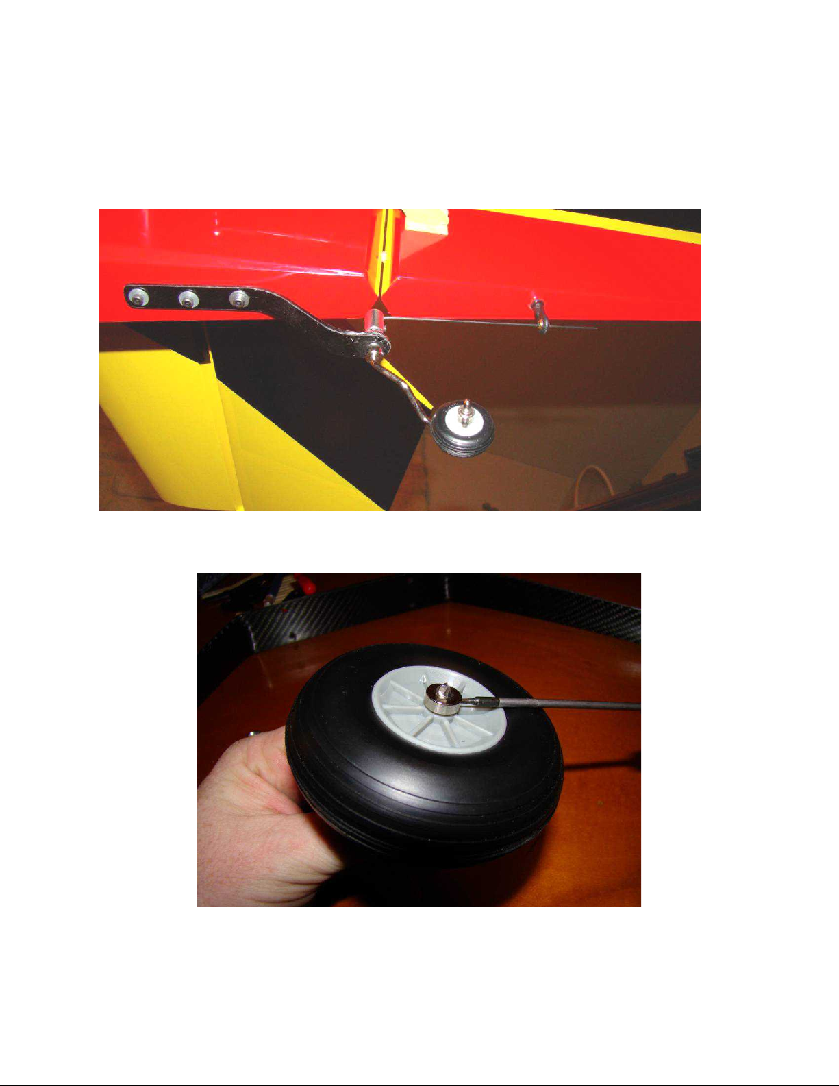
Landing gear
4
User blue loctite to lock all of the set screws on the tailwheel assembly and re-tighten them.
Attach the tailwheel to the bottom of the fuse as shown with 3 x 3mm screws and washers. Use blue
loctite on these screws.
Main Wheels: Place one wheel collar over the axle, then the main wheel, then the other collar and tighten
as shown.
Insert the wheels and axles into the wheel pants and attach to the main landing gear with the nylock nuts.
Install two Phillips-head screws through the landing gear and into the pants as shown.
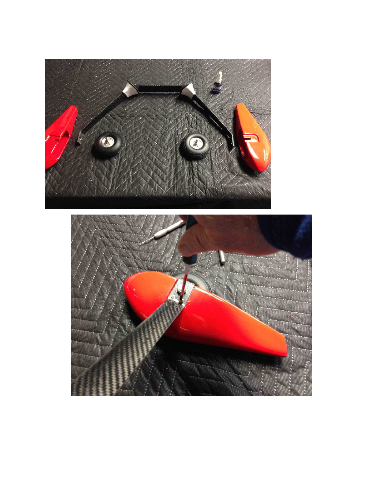
Slide the landing gear-to-fuselage fairings onto the landing gear legs.
5
Insert the wheels/axles into the wheel pants and install onto the landing gear legs. Tighten the
axle nuts. Install wood screws as shown through the gear legs into wheel pants.
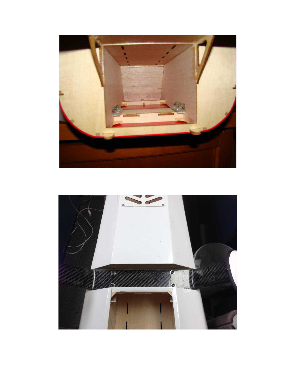
Attach the main gear to the fuselage using 4 x 4mm screws, washers, and locknuts. Note that you will
6
need to use a pliers to hold the nuts inside the fuselage as you tighten the screws that retain the landing
gear.
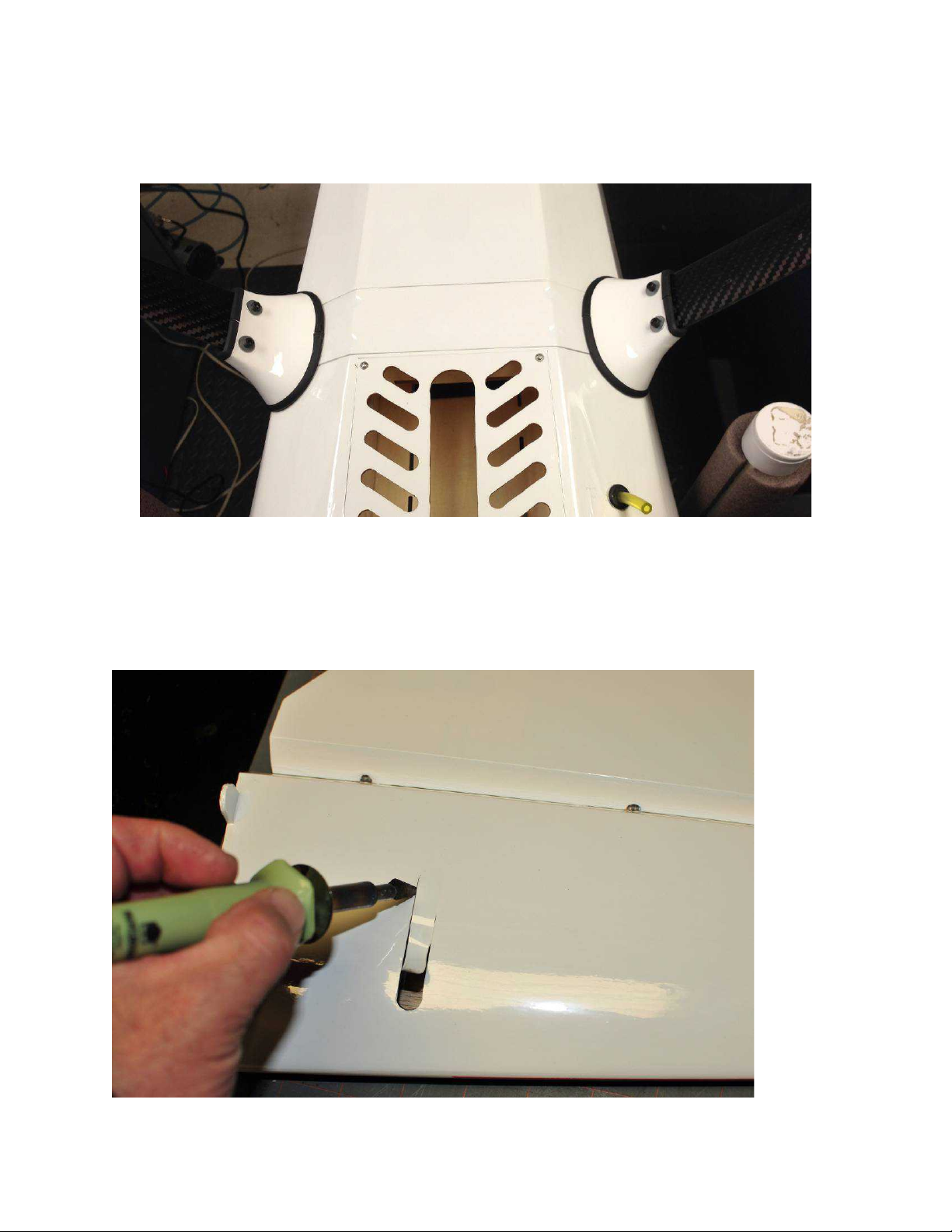
Attach the cover plate over the landing gear screws using epoxy glue or silicone adhesive. Slide the
7
fairings into place and attach with screws as shown.
Elevator servo arm slot
On each stab/elevator half, you will need to locate and open the slot for the servo arm as shown. The
wood is pre-cut, but you will need to remove the covering over the slot as shown. NOTE: The slot is
sized approximately - your particular servo/arm combination may require the slot to be lengthened or
widened.
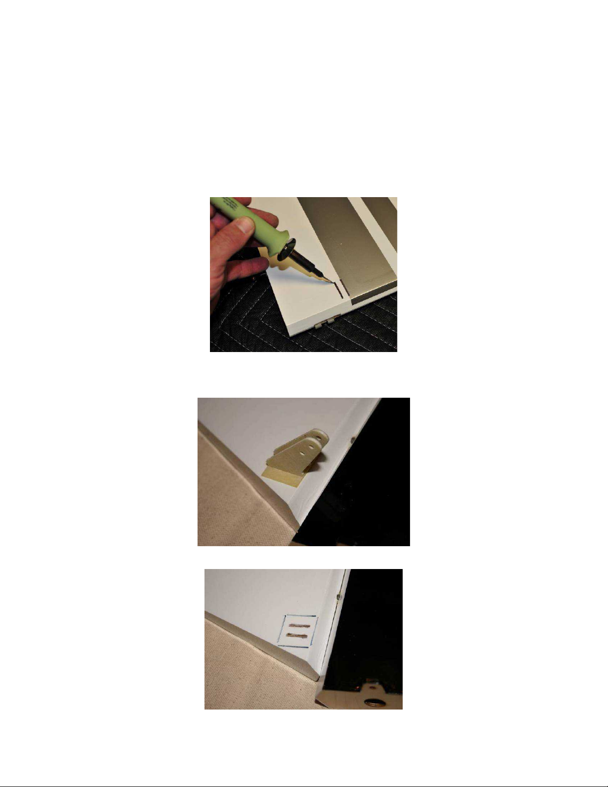
Control Horn Installation
8
Your Edge features phenolic control horns. The slots for the horns are pre-cut into all of the control
surfaces. You will need to remove the covering over each of these locations. The best way to trim
covering on this aircraft is with a hot pencil-tip soldering iron. This method gives a clean cut and also
seals the edges of the covering at the cut line. You can also use a hobby knife if you cannot use a
soldering iron for this job, but the iron is recommended.
1. First, locate the control horn location in each control surface.
2. Cut away the covering over the two slots.
3. Assemble the control horns as shown, and temporarily push the horn into the slots in the control
surface (do not use glue at this time).
4. Using a pencil or marker, mark around the outside of the square base of the control horn.
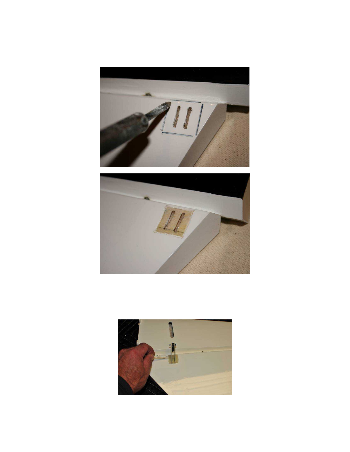
5. Remove the horn and use the soldering iron to trim the covering just inside the square mark you made
9
with the pencil.
7. Apply 30-minute epoxy liberally to the bottom of the horn and to the wood of the control surface.
Install the horn. Wipe up excess epoxy with a paper towel and alcohol. Temporarily install a 3mm bolt
and rod end through the bolt holes to ensure proper alignment of the two horn halves. Wipe up excess
epoxy that squeezes out. Allow the epoxy to cure.
 Loading...