

Extreme Flight 110"" YAK-54 V2 Assembly Manual

110" YAK-54 V2
Assembly Manual
1
Copyright Extreme Flight 2015

Please take a few moments to read this instruction manual before beginning
assembly. We have outlined a fast, clear and easy method to assemble this aircraft
and familiarizing yourself with this process will aid in a quick, easy build. Please
read the following paragraph before beginning assembly of your aircraft! THIS IS
NOT A TOY! Serious injury, destruction of property, or even death may result
from the misuse of this product. Extreme Flight is providing you, the consumer,
with a very high quality model aircraft component kit, from which you, the
consumer, will assemble a flying model. It is beyond our control to monitor the
finished aircraft you produce. Extreme Flight RC will in no way accept or assume
responsibility or liability for damages resulting from the use of this user assembled
product. This aircraft should be flown in accordance with the AMA safety code. It
is highly recommended that you join the Academy of Model Aeronautics in order
to be properly insured and operate your model at AMA sanctioned flying fields
only. If you are not willing to accept ALL liability for the use of this product,
please return it to the place of purchase immediately. Extreme Flight RC, Ltd.
guarantees this kit to be free of defects in materials and workmanship for a period
of 30 DAYS from the date of purchase. All warranty claims must be accompanied
by the original dated receipt. This warranty is extended to the original
purchaser of the aircraft kit only. Extreme Flight RC in no way warranties its
aircraft against flutter. We have put these aircraft through the most grueling flight
tests imaginable and have not experienced any control surface flutter. Proper servo
selection and linkage set-up is absolutely essential. Inadequate servos or improper
linkage set up may result in flutter and possibly the complete destruction of your
aircraft. If you are not experienced in this type of linkage set-up or have questions
regarding servo choices, please contact us at info@extremeflightrc.com or 770887-1794. It is your responsibility to ensure the airworthiness of your model.
2

Congratulations on your purchase of the Extreme Flight RC 110” Yak 54 EXP
ARF! The Yak is loaded with unique features, including first rate hardware,
components and thorough instructions to ensure a trouble free assembly and set-up.
Weight saving components are used throughout, such as carbon fiber structural
reinforcement, carbon fiber wing and stab mounting tubes, carbon fiber landing
gear, titanium pushrods and a carbon fiber tail wheel assembly, all ensuring the
lightest, most high performance aircraft possible. You will notice there is a box
built into the bottom of the fuselage. This is apipe tunnel and will accommodate
most canister mufflers and tuned pipes sold for the current makes gas engines.
The performance ability of the Extreme Flight RC Yak-EXP is phenomenal! This
airframe is completely unlimited in its ability to perform the full range of full stall
high alpha maneuvers and aggressive gyroscopic tumbling maneuvers. Rock solid
in all aspects of current 3D maneuvers, the Yak will give those that fly on the
bleeding edge the confidence and capability to push through and break new ground
in expanding the rapidly evolving 3D flight envelope. Utilizing the same
lightweight interlocking laser cut construction and carbon reinforcement as our 104
inch Extra, the Yak is capable of handling the most punishing maneuvers
imaginable. We have spent a great deal of time and effort to provide you, the
discriminating aerobatic enthusiast, with the highest quality, most complete
package possible. We are very proud of the end result of our labor and wish you
great success with the assembly and flying of your Extreme Flight RC 110 inch
Yak 54!
Items needed for completion:
3

Masking or painters tape.
Hobby knife with #11 blades.
Fresh Thin and medium CA. We highly recommend Mercury M5T thin and
M100XF medium formulas as well as the Mercury glue tips.
Fresh 30 minute epoxy. Mercury Adhesives Epoxies have worked very well for
us.
Blue and Red Loctite thread locking compound.
Electric drill with an assortment of small drill bits.
Small flat head and Phillips head screw drivers.
Standard and needle nose pliers.
Side cutters.
Metric ball driver or allen key set. (especially 2.5 and 3mm drivers)
Sanding block and sandpaper.
7 400oz (min) torque servos. (8 servos if you use 2 rudder servos)
1 x standard size servo for the throttle.
4 x 1.5” single aluminum Servo Arms for the ailerons (half arms)(6 half arms if
utilizing the 3rd/center aileron option)
2 x 2” single aluminum arms for the elevators (3 if using a tail mounted rudder
servo and 4 for two rudders servos)
1 x 4.5” double offset aluminum arm for the rudder if using pull-pull rudder setup.
2 x 36” for outboard aileron Servos Extensions (Inboards are close enough to not
need any extensions
2 x 48”- 60” Servo Extensions. If you need to remove the stabs frequently for
transport use 54”-60". May need 3 (or 4) if using tail mounted rudder servo(s).
5” Spinner, 85cc-120cc gas engine and recommended prop.
Engine standoffs, 1.75” length if using the recommended DA120
Some type of engine muffling (stock, cannisters or tuned pipes and headers)
Receiver, batteries, switches, fuel tank, fuel dot and tubing.
Tips for Success:
4

1. Before starting assembly, take a few minutes to read the entire instruction
manual to familiarize yourself with the assembly process.
2. Go over all the seams on the aircraft with a covering iron on a medium heat
setting. Also, due to climate changes, wrinkles may develop in the covering. These
are easily removed with a little bit of heat. Use a 100% cotton tee-shirt and your
heat gun and
heat the covering while gently rubbing the covering onto the wood with the t-shirt.
Be careful not to use too much heat as the covering may shrink too much and begin
to lift at the edges. Take your time, and a beautiful, paint-like finish is attainable.
3. Apply CA to high stress areas such as servo mounting trays, landing gear
mounts, anti-rotation pins, wing and stab root ribs, and motor box joints etc.
4. By the time your aircraft arrives at your door step, it will have been handled by a
lot of people. Occasionally, there are small dings or imperfections on some of the
surfaces. An effective method to restore these imperfections to original condition is
to use a very fine tipped hypodermic needle and inject a drop of water under the
covering material and into the ding in the wood. Apply heat to the area with a
sealing iron and the imperfection will disappear. Deeper marks may require that
this process be repeated a couple of times to achieve the desired result, but you will
be surprised at how well this technique works.
5. Use high quality, fresh epoxy for installing the composite control horns and
hinges. We highly recommend Mercury Adhesives 30 minute Epoxy as well as
Pacer Hinge Glue. We are very pleased with the results and ease of application and
cleanup of these products.
6. Take the time to properly balance and trim your aircraft and set up rates with
exponential values. Your flying experience will be greatly enhanced once your
plane is properly dialed in.
7. Extreme Flight now has their own Vimeo channel and we highly recommend
viewing the assembly videos on this resource. There are many assembly videos
providing extreme detail on certain aspects of the assembly of this very model and
performed by Jeff Williams. However, if you are assembling a different Extreme
Flight model many of these videos are still applicable as some aspects are the same
regardless of the aircraft type. https://vimeo.com/user40004054
5
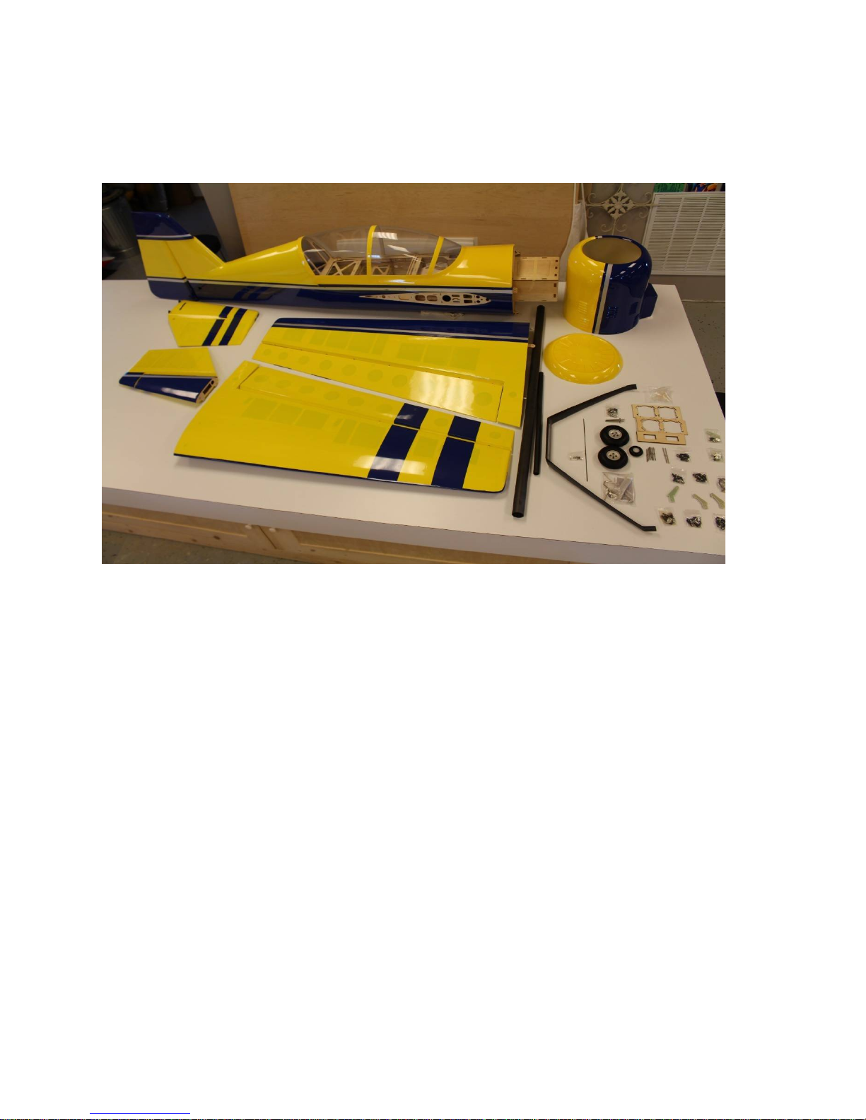
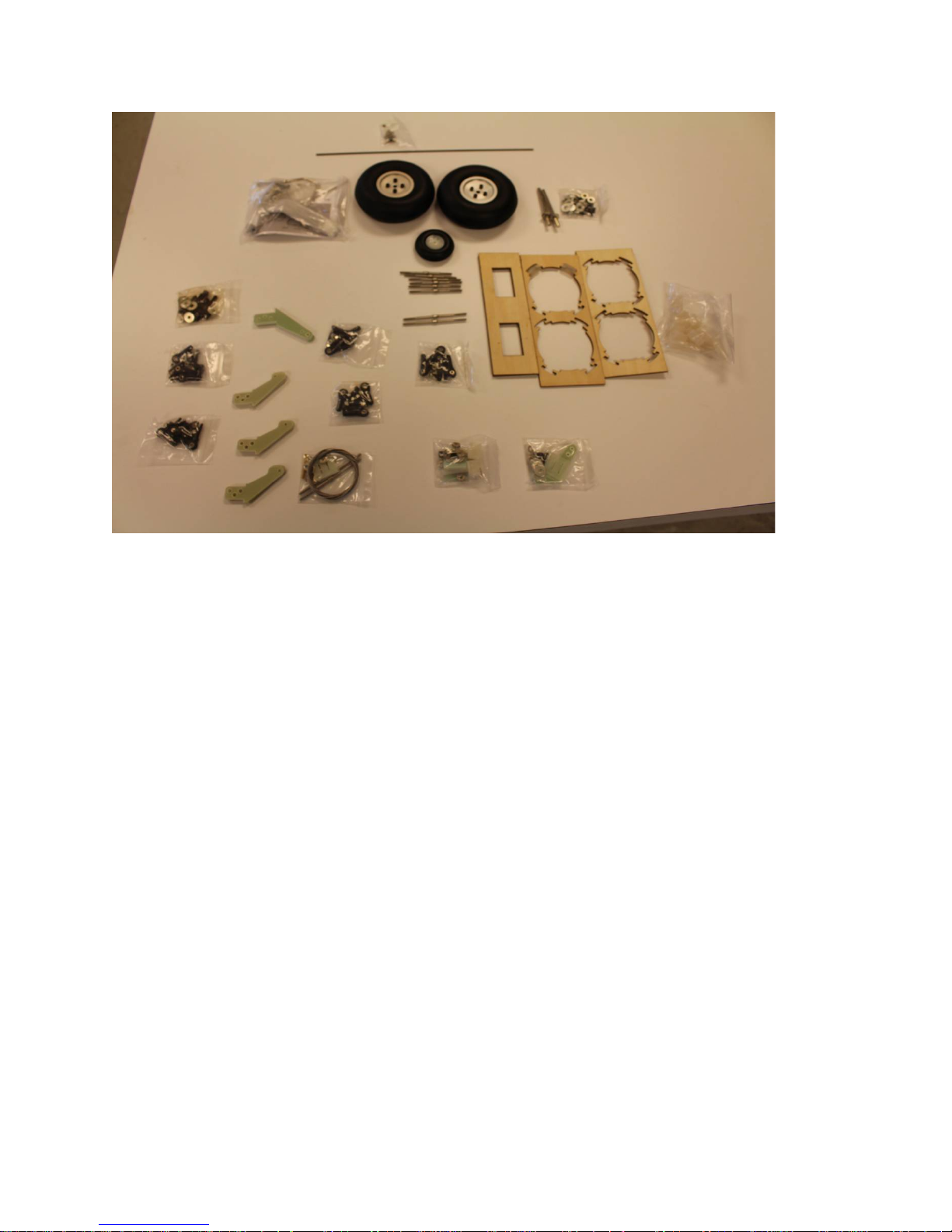
Here are the included kit components:
Hardware packages
6
Let's begin:
1. Locate the wing panels/ailerons and horizontal stabilizers/elevators and
associatedhardware bags. We will begin by hinging all of these at one time. I
suggest you scuff/roughthe surface of the hinges, they are slick from the
manufacturing process and the glue willadhere better to a non-slick surface. Using
100-150 grit sandpaper works well to do this, be sure you don't sand the barbs off
the hinge, you just want a little scuffing on the hinge, do not sand at the pivot
point. I strongly recommend 30 minute (or slower curing) epoxy for installing
hinges. I apply 3-4 drops of glue in the hinge hole and then using a toothpick, or
similar, suave the glue around the insides of the hinge hole. Do this on just one
surface, either the wing/horizontal or aileron/elevator it does not matter which is
first. Mix only enough glue to work with one panel at a time. Before applying any
glue to the hinge itself, I highly recommend you protect the hinge pin (pivot point)
from glue. I use Vaseline, but tape will work however it is harder to remove later,
in any case apply a protectant to the center of the hinge so gluecannot penetrate
that pin, it will cause binding. Once you have the holes lathered withglue, apply a
small amount to the hinge barbs and insert into the hinge hole twirling it as you
7

insert it until the pin is even with the hinge line. Be sure your hinge pivots freely
and is perpendicular to the hinge line. Allow to dry, then mate to the appropriate
surface (wing toaileron/horizontal stabilizer to elevator) and allow that to dry.
Refer to figure 1 for the 3 clipped horizontal stabilizer hinges, all other hinges are
normal length.
NOTE: All hinges are the same, except the 3 most inner hinges on the horizontal
stabilizer. The stabilizer tube socket necessitates the trimming of these 3 hinges, be
sure to follow Figure 1 and that those hinges are in the correct holes.
Figure 1
8

At this point you should have the both wings/horizontal stabilizer and
ailerons/elevators hinged. Now check that each hinge moves freely, if not then
work the hinge till it does move freely. If it is still binding, apply a very small drop
of 3in1 oil to the pin only. Again work the hinge in both directions and it should
now move freely. (It is acceptable to also install the rudder hinges into the vertical
stabilizer only at this time, we will mate the rudder and do other assembly later.)
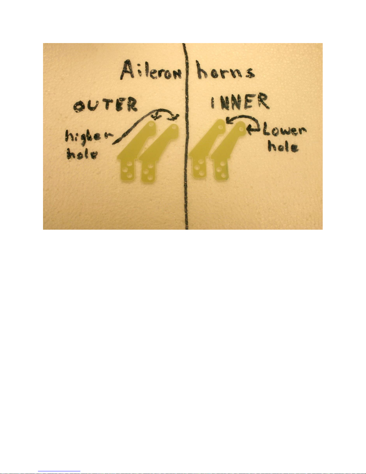
2. Locate your control horns, base plates, ball links, 3mm bolts so we can install
the control horns. Again it is fine to perform this on the wings/ailerons and
horizontal/elevators at the same time. Figure 3 shows the elevator hardware for this
step. The aileron hardware is nearly identical, except the control horns are location
specific. The horns with the lowest hole for the ball link are the inner most, the
ones with the highest holes go to outer most location. If using the middle/3rd
aileron servo then the remaining horn with the hole in the middle of the horn would
be for that location. See figure 2.
Figure 2.
9
10
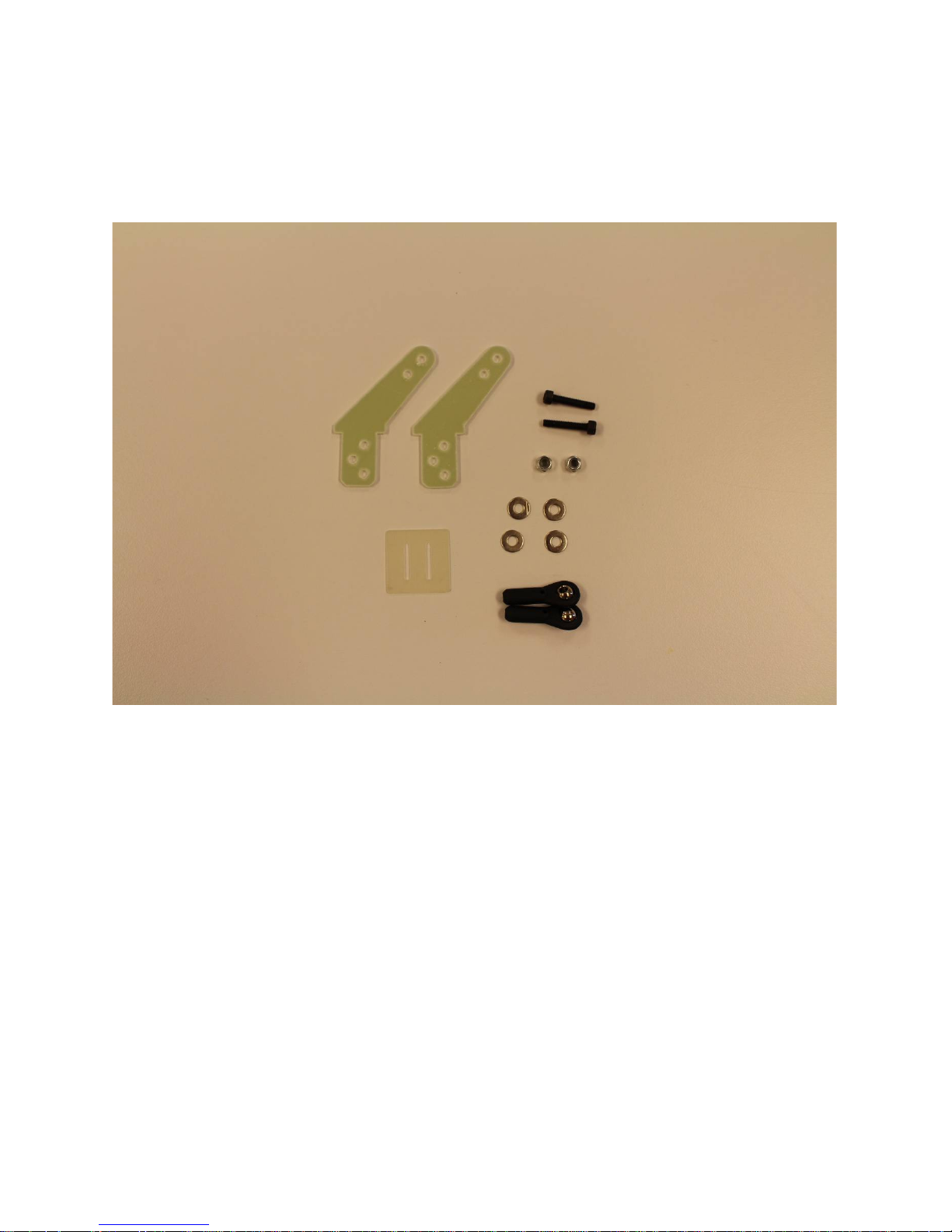
Figure 3.
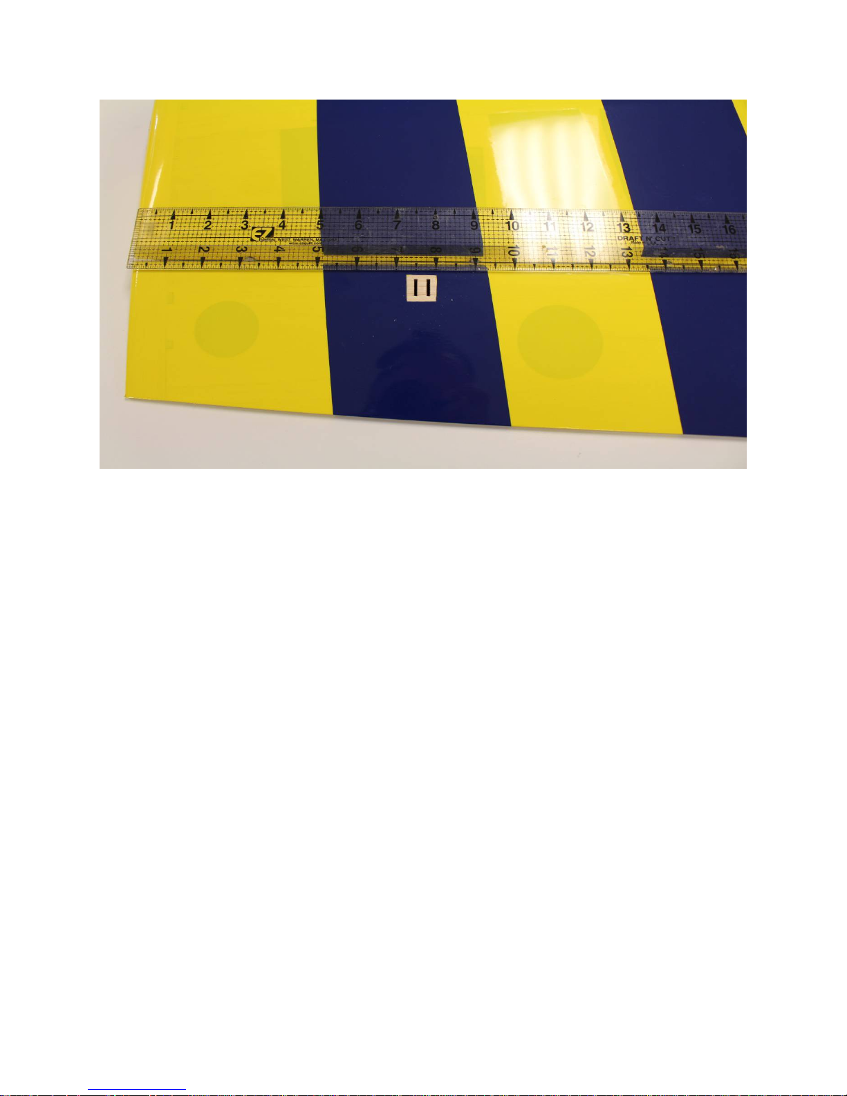
Now is the time to decide if you will run 2 or 3 aileron servos. If you are running
servos that have at least 400oz inches of torque, two should be sufficient. We
chose the MKS777HV for our ailerons. You can always add the middle aileron
servo later if you find it necessary. We will describe how to install a 2 servo
operation. Find the inner most slots in the aileron for the control horns. They are
approximately 5.25” from the root of the aileron measured along the hinge line.
See figure 4. The outer aileron horn slot is 7.5” from the tip, see figure 5.
11

Figure 4. 5.25” inner aileron slot
Figure 5. 7.5” outer aileron slot
12
Remove the covering to expose ONLY the slots. Now take the control horns and
trial fit them thru the base plate and then into the slots. Now use blue tape or other
method to determine how much covering to remove from under the base plate to
attain a base plate to wood joint. I typically leave 1/16” or 2mm of covering that
will stay under the outer edges of the base plate. Once you are happy with this take
the base plate and horns back out and scuff the lower section of the horn that will
insert into the slot and the back side of the base plate, this will provide better
adhesion. Now drop 2-4 drops of 30 minute epoxy in the slots and thoroughly coat
the portion of the control horn that will be inserted in the slot and install the base
plate and control horns.
TIP: install the ball link with the 3mm bolt while these control horns dry, this will
keep them properly aligned.
3. The horizontal stabilizers/elevator control horns are installed the exact same
way. Now is a good time to install those also.
13
4.Gather your aileron and elevator servos, all servo arms and hardware so we can
install those items. I will discuss the elevator installation, but the ailerons install
very similarly. I found it is easier to mount the servos without the servo arm
attached, so install your elevator servo into the slot and secure with the
manufacturers recommended screws. You will need to retrieve the servo wire back
thru the hole in front of the servo, hemostats are very handy for this. The outer
aileron servo will require a 36” extension.See figure 6 for our installation.
Figure 6
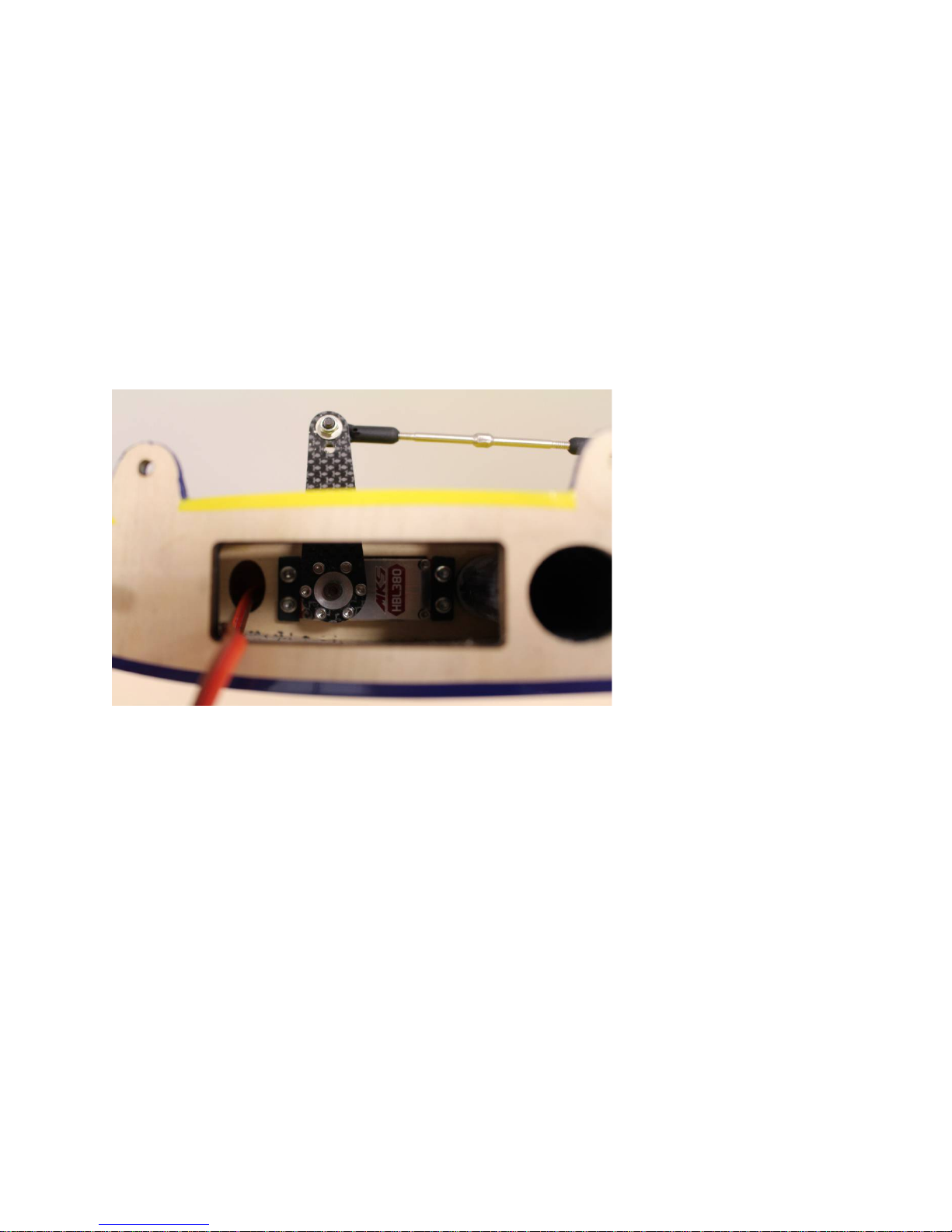
5. Now that the elevator and aileron servos are installed, lets hook up the pushrods
and ball links. Locate the pushrods/ball links/3mm bolts/nylon insert nuts/washers
from the respective hardware bags.
This procedure will serve as the direction for all servo to control horn linkages on
this plane. First, electronically center your servos. Now thread the ball links onto
the pushrod, note that one will thread on with right hand threads and the other has
left hand threads. It does not matter which ball link you use, just thread them on
according to the thread direction. Make sure they are on at least 10 complete turns,
however I noted that there were only a few threads showing once I centered
everything during my setup. Now put the ball link in between the control horns and
insert the 3mm bolt with washer thru the control horn and ball link. Now install a
washer, blue thread lock and the nylon insert nut. Now install the ball link into the
servo arm using the same sequence as the control horn. Figure 8 shows a
completed elevator setup.
14
 Loading...