

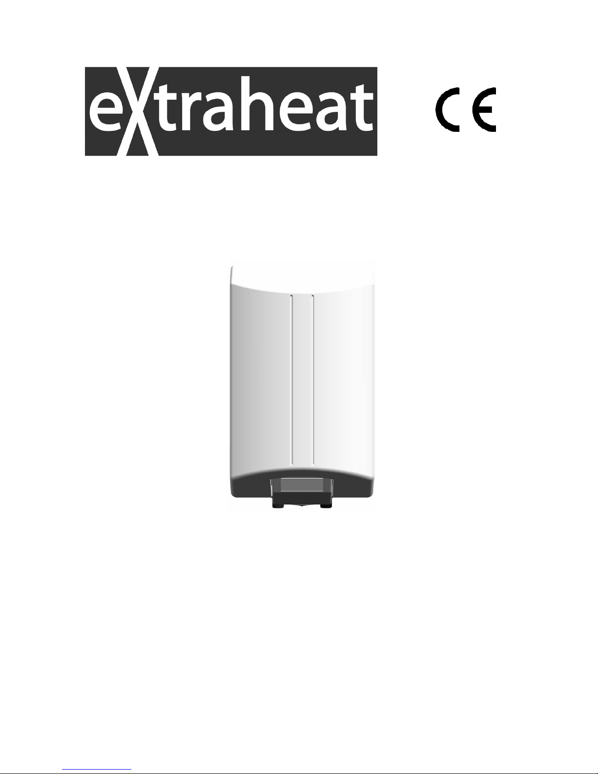
Extraheat RAPID 10, RAPID 15, RAPID 30 Instructions For Installation, Use And Maintenance Manual
Page 1
Cod. 122591 – Agg. 28.05.2010
RAPID 10–15–30
ELECTRIC UNVENTED WATER HEATER
INSTRUCTIONS FOR INSTALLATION, USE AND MAINTENANCE
Page 2
the nation’s favourite for
PLUMBING & HEATING SUPPLIES
SECURE PAYMENTS
shop online with confidence
FREE SHIPPING
on all orders over £100 to mainland UK
FINANCE AVAILABLE
spread the cost with low interest rates
PRICE MATCH
always get the best deals available
Boilers
Radiators
Heating controls
Cylinders
Fires
Renewable energy
Bathroom suites
Kitchen sinks & taps
Showers
Wet rooms
Towel warmers
Bathroom furniture
& much more
HUGE REDUCTIONS
we have
ON THOUSANDS OF ITEMS
0844 800 3460
CALL US ON
visit our website
plumbnation.co.uk
Page 3

Page 4

1
1) TECHNICAL AND DIMENSIONAL CHARACTERISTICS
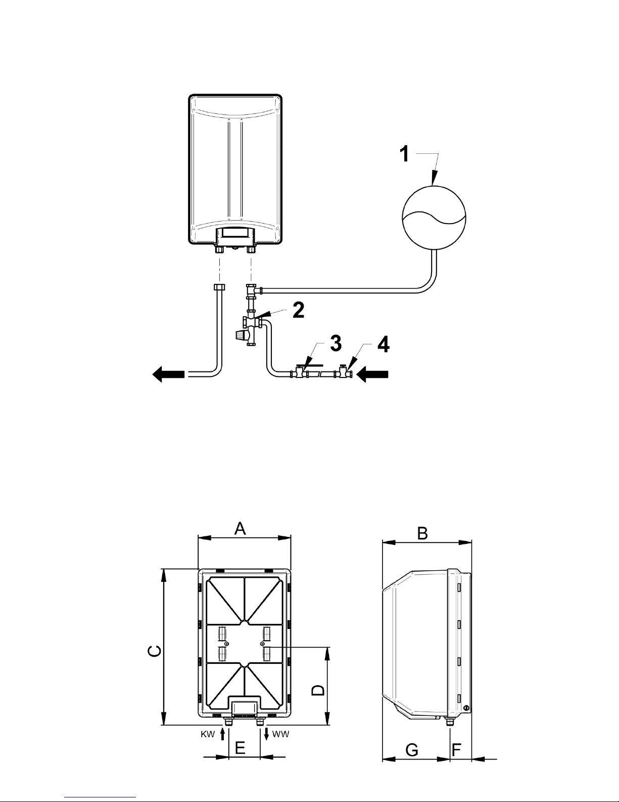
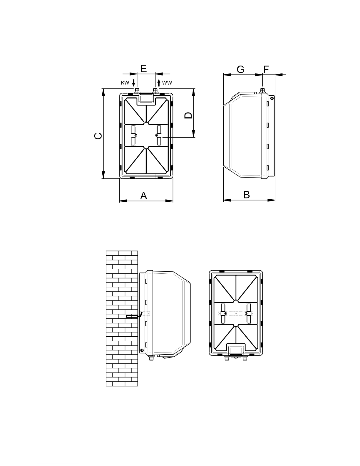
The technical and dimensional characteristics of the appliances are given, according to the model, in Figures 4, 5 and in the
Table of Dimensions, table 1. The electrical specifications are given on the appliance, according to the model.
2) GENERAL INSTRUCTIONS
Installation is the customer’s responsibility. The Manufacturer declines any liability for damage due to incorrect installation and
non-compliance with the instructions contained in this user’s handbook, and in particular:
• the electrical connection must comply with that specified in the relevant section;
• the “water safety unit” must be correctly installed, efficient and not tampered with;
• installation and maintenance must be carried out by qualified personnel in compliance with current regulations;
• the maintenance instructions must be respected;
• the appliance must be installed in a suitable closed room (to avoid appliance freezing);
• the appliance is only intended for domestic use.
This appliance complies with the current provisions of EEC Directives.
The internal boiler is designed to withstand a max. pressure of 0.8 Mpa (8 bar) without deformation.
3) INSTALLATION (BY QUALIFIED PERSONNEL ONLY)
IMPORTANT: The appliances must be installed in compliance with the provisions of the EN standard regarding
placing in bathrooms; they must be installed according to the version (oversink and undersink) as shown on the
packing.
Oversink appliances must not be installed as undersink applications, and vice versa.
No type of conversion is possible because the type of heating element and the safety and adjustment thermostat
setting do not allow it.
3.1. Wall mounting
After checking that that wall is strong enough fix 2 hooks of suitable size (not supplied) to it, making sure they a securely
anchored. Then hang the appliance on the hooks by means of the support bracket, as shown in fig. 6.
3.2. Anode.
The magnesium anode fitted inside the appliances, together with the special treatment inside the boiler, guarantees protection
against corrosion of the tank.
3.3. Water connection
The water inlet and outlet are marked as follows:
- blue ring for the cold water inlet;
- red ring for the hot water outlet.
It is advisable to place the appliance near the main hot water drawing point in order to avoid heat loss along the piping, and
possibly near a drain to facilitate emptying operations. The appliance water connection is shown in Fig. 3. The procedure for
correct installation is illustrated below.
3.3.1. Water safety kit
Compulsory – The 6 bar pressure relief safety valve supplied with the unit must always be installed. No other valves, controls
or devices can be fitted between the safety valve and the heater. This safety valve should be piped to discharge at safe and
visible point complying with current building regulations.
3.3.2. Pressure reducing valve
If the incoming mains static water pressure exceeds 5 bar a pressure reducing valve must be installed to protect the heater
(Fig. 3, Ref. 4). It should not be installed between the unit and the pressure relief valve and sufficient pipework distance should
be allowed for expansion.
Page 5

2
3.3.3. Expansion provision
It is acceptable for the expansion of the hot water to be accommodated in the pipework where conditions permit. The minimum
(15 mm) pipework distance to the nearest cold water drawoff should be 2,8 m (10 litre) or 4,2 m (15 litre) and there must be no
check valve, stop valve or other device preventing reverse flow within this distance.
Where this is not possible a suitable expansion kit should be installed (Fig. 3, Ref. 1) comprising expansion vessel, non-return
check valve and pressure reducing valve.
3.4. Filling the appliance
WARNING: Switching the appliance on when not completely filled with water will seriously damage the
electric heating element.
IMPORTANT: In the presence of water with a hardness value >20°TH (where 1°TH=degree French=10mg
CaCo3/l) a water softener must be installed to reduce scaling inside the boiler and preserve the efficiency of
the electric heating element and water safety unit.
To fill the appliance:
- bring the cock located on the hydraulic unit (Fig. 3 ref. 3) to the operating position, opening the cock enables appliance filling.
The non-return valve incorporated in the water safety unit prevents the return of hot water;
- open the main water supply or the appliance water feed cock;
- open the main water supply or the appliance water feed cock;
- open a hot water tap (e.g. bath, sink, etc.) to allow the discharge of air inside; the appliance is full when water flows freely from
the tap;
- check for any leaks in the various plumbing connections;
It is advisable to clean the pipes before installation.
The electrical connection can only be made after this operation.
3.5. Electrical connection
NB: The appliance is arranged for installation with fixed pipe for the electrical connection.
Make sure the mains voltage matches the value given on the appliance dataplate and that the electrical mains
can supply the power specified.
A double-pole switch conforming to EN standards (contact opening of at least 3 mm, preferably with fuses) must be used for
disconnecting the appliance from the mains. Connection must be made by removing the electrical protection cover and
inserting the power cable in the special plastic sleeve as far as the thermostat. The electrical connection is made by connecting
the cable directly to the thermostat terminals L(L1) and N(L2 ).
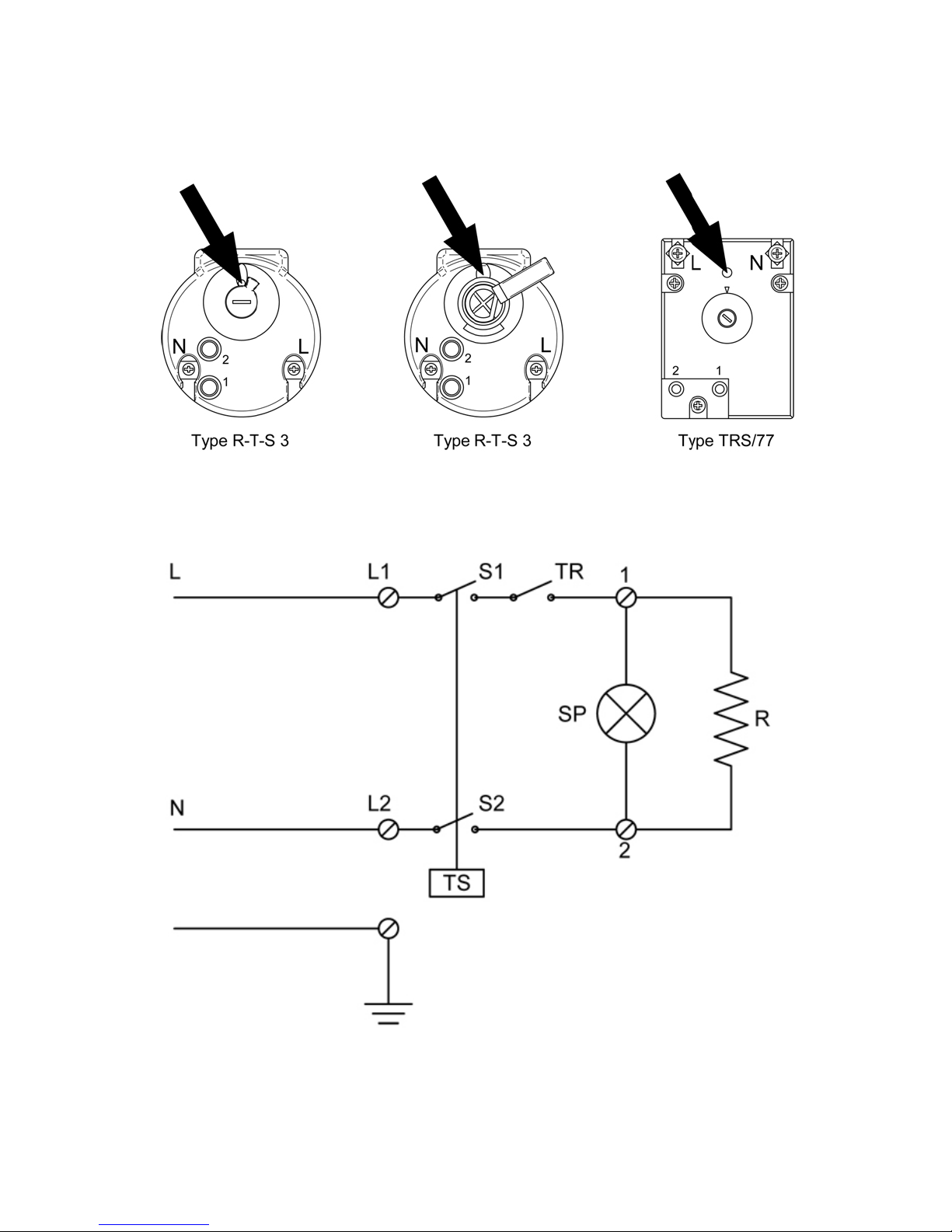
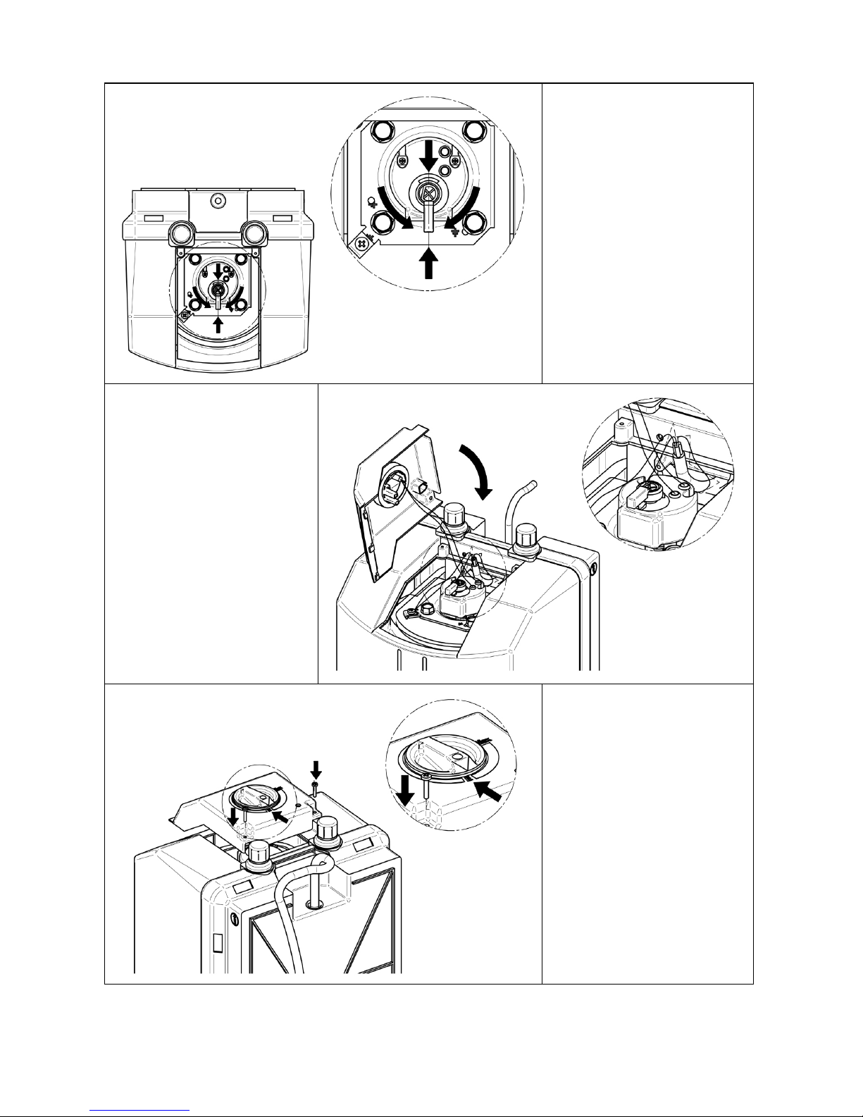
For versions with external selector see the diagram attached to the cover and included in these instructions (Fig. 8, 9 and 10).
The appliance must be earthed and the earth wire (yellow/green) fixed to the special earth terminal. Given below is the key of
the wiring diagram in Fig. 1.
R = Electric heating element; S1, S2 = Thermostat contacts;
TS = Thermostat safety device; TR = Contact operated;
L-N = Power supply line: SP = Indicator light;
L1, L2 = electric line connection terminals; = earth;
IMPORTANT: Before fitting the electrical protection cover make sure the safety device located on the
thermostat is on (see the section “Safety limiting device”).
Switching the appliance on when not completely filled with water will seriously damage the electric heating
element.
Page 6
3
4) OPERATING INSTRUCTIONS (USER)
4.1. Switching on
Before switching the appliance on check correct electrical connection and water filling. The appliance has an adjustment
thermostat that automatically controls the water temperature; the indicator light stays on only during the heating phase.
CAUTION: Before switching the appliance on, always make sure it is filled with water, in order to avoid
serious damage to the electric heating element.
4.2. Dripping from water safety unit.
Dripping of the water safety unit is normal during the heating phase.
With heating, the water expands and cannot be compressed. If the plumbing system is unable to absorb this increased volume
the internal pressure increases, causing intervention of the safety device which, by discharging the excess water, prevents
overpressures in the tank - see the section “expansion tank” par. 3.3.3.
4.3. Temperature adjustment
IMPORTANT: The possibility of thermostat adjustment allows power consumption to be optimised according
to the comfort required (hot water temperature). However, in order to prevent “legionella” bacteria to form it is
advisable not to allow the stored water temperature to become too low. Therefore, comply with the following
general prevention measures:
• Keep the hot water inside the appliance at a temperature of not below 50°C;
• In case a prolonged absence let water run from taps and showers for a few minutes;
• Keep showers and taps clean of scale;
4.3.1. Models without external selector.
The thermostat is factory-set to max. value; to change the setting disconnect the power supply
then remove the protection
cover, turn the thermostat knob Fig. 1 towards “+” to increase or “-“ to decrease the temperature. Refer to the relevant notch
located on the thermostat. To prevent the formation of “legionella” an adjustment close to the factory setting (towards the “+”
notch) is advisable.
4.3.2. Models with external selector.
Adjustment is made by turning the knob (selector) located on the cover (see fig. 10). Max. temperature setting is obtained by
turning the selector in the proximity of the wording “MAX” screen-printed on the cover (see Fig. 10).
Position “E” enables use between comfort and economy setting. It is advisable to adjust the temperature to between “E” and
“MAX” in order to prevent the formation of “legionella”
4.4. Safety limiting device
The appliances are equipped with a thermostat with safety limiting device (see Fig. 2), in compliance with current CEI-EN
standards. The limiting device intervenes in case of abnormal water heating, automatically disconnecting the power to the
electric heating element. Resetting is manual.
The operation can be carried out by the user as indicated in par. 5.1.
If the anomaly reoccurs contact qualified personnel.
4.5. External cleaning
Clean the outer casing using neutral soapy solutions and never organic solvent-based abrasive products (alcohol, petrol, etc.).
4.6 Water safety unit efficiency check.
The efficiency of the water unit is very important for preventing overpressures inside the tank (damaging it) and allows safe use
of the appliance. Periodically check the efficiency of the water safety unit by following the manufacturer’s instructions. When
checking, also clean and remove any scale.
4.7. Emptying the appliance
In case of prolonged absence it is advisable to completely empty the appliance. In which case proceed as follows:
- switch off the power and close the main water supply;
- open a hot water tap to allow the entry of air;
- turn the emptying knob on the water safety unit (Fig. 3) to the open position;
Page 7
4
- make sure the water safety unit discharge union is connected to a drain as provided for in par.3.3.1.
Reconnect the power only after this operation
.
5) MAINTENANCE INSTRUCTIONS (QUALIFIED PERSONNEL ONLY)
IMPORTANT: repair and/or maintenance operations must be carried only using original spare parts and by
qualified personnel. Before performing any maintenance operation, disconnect the appliance from the power
mains.
5.1. Safety limiting device (manual reset )
Reset, after eliminating the causes of intervention, as follows:
- disconnect the power supply;
- remove the protection cover fixing screws;
- lightly press the thermostat reset button, using an insulated object with round tip, in the position indicated in Fig. 1, until
hearing a click.
5.2. Control/Replacement of anode
Its function is very important for protecting the tank against corrosion caused by stray currents or the aggressiveness of the
water. Anode wear is proportional to the protection work carried out and the quality of the water inside.
Make sure to check its efficiency at least every two years
or in any case according to the quality of the water. Protection
efficiency is linked to its integrity. When checking, also check wear; replace if excessively worn or insufficient to guarantee
protection until the next foreseen control. Spare parts are available from the distributor and/or the manufacturer.
IMPORTANT: Remember that damage caused by excessive anode wear (insufficient tank protection) is not
due to manufacturing defects and is therefore not covered by the warranty.
5.2.1. Rapid water heater versions with external selector (Fig 8, 9, 10).
For control and/or replacement, proceed as follows:
- switch off the power to the appliance;
- empty the water from the appliance by following the instructions given in the relevant section;
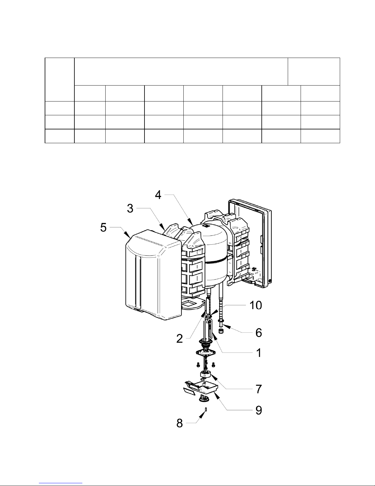
- remove the electrical protection cover (Fig. 7 Ref. 9) using a screwdriver and disconnect the electrical wires and indicator
lamp from the respective terminals;
- remove the thermostat;
- remove the counterflange using a suitable spanner for M10 nuts and remove it from the housing;
- check the good condition of the anode and replace if necessary, removing it together with its support with the aid of pliers (the
anode holder is screwed onto a special threaded housing) Fig. 7 Ref. 2;
- tighten the M10 nuts with torque setting of 12 Nxm; carry out in cross tightening order. Make sure to correctly position the
gasket and the screws on which the nuts are tightened;
- carry out the specific instructions for connection and fitting of the cover with external selector (Fig. 8, 9, 10).
- fill the appliance according to the instructions given in the relevant section, then reconnect the power.
5.3. Descaling (periodical).
To ensure good appliance efficiency it is advisable to periodically clean any scale from the heating element. The frequency of
this operation depends on the water hardness; proceed as follows:
5.3.1. Versions with external selector – heating element on flange
- switch off the power to the appliance;
- empty the tank (see section on emptying the appliance);
- remove the electrical protection cover (Fig. 7 Ref. 9) using a screwdriver;
- disconnect the electrical wires and indicator lamp from the respective terminals;
- remove the thermostat;
- remove the heating element fixed to the counterflange by means of an M6 hexagon-head screw;
- remove any scale and clean, taking care not to damage the heating element armour.
- refit, tightening the M10 nuts with torque setting of 12 Nxm; carry out in cross tightening order. Make sure to correctly position
the seal and the screws on which the nuts are tightened.
- carry out the specific instructions for connection and fitting the cover with external selector (Fig. 8, 9 and 10).
- fill the appliance according to the instructions given in the relevant section, then reconnect the power.
Page 8

5
5.4. GENERAL NOTES
Use equipment suitable for the purpose.
Always replace the seal gaskets and/or O-rings.
Only use original spare parts.
When refitting, make sure:
- the heating element is correctly housed and that the seals are correctly fitted;
- the thermostat is inserted in the housing of the heating element, pushing it all the way in but without any striking that can
damage it; make sure the internal male/female contacts are correctly inserted;
- for models with external selector follow the specific assembly instructions (Fig. 8, 9, 10);
- before reconnecting the power, fill the appliance (see the relevant section) and check for any water leaks.
6) KEY OF DIAGRAMS AND FIGURES
Fig. / Drg. 3, 4 and 5 Fig. / Drg. 13, 14, 15
1. MEMBRANE EXPANSION TANK (*)
2. 6 BAR PRESSURE SAFETY VALVE - SUPPLIED
3. COLD WATER FEED COCK (*)
4. PRESSURE REDUCER (*)
1.
A
node inspection cover
2. Magnesium anode
3. Thermometer
4. Thermal insulation
5. Tank
6. External casing
7. Electric heating element
8. Water inlet shower
9. Thermostat
10. Indicator light
11. Protection cover
12. Hot water outlet pipe
13. Rear support bracket
Page 9
6
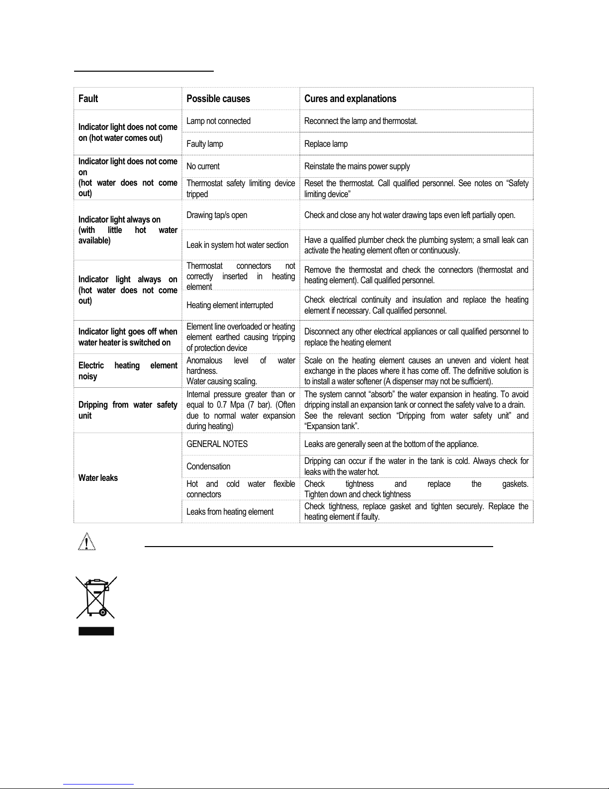
7) TROUBLESHOOTING
Fault Possible causes Cures and explanations
Indicator light does not come
on (hot water comes out)
Lamp not connected Reconnect the lamp and thermostat.
Faulty lamp Replace lamp
Indicator light does not come
on
(hot water does not come
out)
No current Reinstate the mains power supply
Thermostat safety limiting device
tripped
Reset the thermostat. Call qualified personnel. See notes on “Safety
limiting device”
Indicator light always on
(with little hot water
available)
Drawing tap/s open Check and close any hot water drawing taps even left partially open.
Leak in system hot water section
Have a qualified plumber check the plumbing system; a small leak can
activate the heating element often or continuously.
Indicator light always on
(hot water does not come
out)
Thermostat connectors not
correctly inserted in heating
lmn
Remove the thermostat and check the connectors (thermostat and
heating element). Call qualified personnel.
Heating element interrupted
Check electrical continuity and insulation and replace the heating
element if necessary. Call qualified personnel.
Indicator light goes off when
water heater is switched on
Element line overloaded or heating
element earthed causing tripping
of protection device
Disconnect any other electrical appliances or call qualified personnel to
replace the heating element
Electric heating element
noisy
Anomalous level of water
hardness.
Water causing scaling.
Scale on the heating element causes an uneven and violent heat
exchange in the places where it has come off. The definitive solution is
to install a water softener (A dispenser may not be sufficient).
Dripping from water safety
unit
Internal pressure greater than or
equal to 0.7 Mpa (7 bar). (Often
due to normal water expansion
during heating)
The system cannot “absorb” the water expansion in heating. To avoid
dripping install an expansion tank or connect the safety valve to a drain.
See the relevant section “Dripping from water safety unit” and
“Expansion tank”.
Water leaks
GENERAL NOTES Leaks are generally seen at the bottom of the appliance.
Condensation
Dripping can occur if the water in the tank is cold. Always check for
leaks with the water hot.
Hot and cold water flexible
connectors
Check tightness and replace the gaskets.
Tighten down and check tightness
Leaks from heating element
Check tightness, replace gasket and tighten securely. Replace the
heating element if faulty.
CAUTION: All operations must be carried out with the appliance disconnected from the power mains.
DISPOSAL OF OBSOLETE ELECTRICAL AND ELECTRONIC APPLIANCES
(DIRECTIVE 2002/96/EC – WEEE)
This symbol indicates that the appliance must not be treated as domestic waste upon disposal.
Rather, it must be delivered to an authorized collection centre for the recycling of electrical and electronic
appliances.
Proper disposal of this appliance will avoid potential health hazards and adverse consequences for the
environment.
The recycling of materials helps to conserve natural resources.
For further information about the recycling of this appliance, please contact your municipal offices, your domestic
waste disposal service or the retailer/installer from whom the appliance was purchased.
The penalties for failure to comply with these disposal procedures are laid down in local legislation.
Page 10
7
SCHEMA ELETTRICO/ WIRING DIAGRAM
Fig. 1
SCHÉMA ÉLECTRIQUE / SCHALTBILD/ ESQUEMA ELÉCTRICO
Fig. 2
Page 11
8
Fig. 3
Fig. 4
RAPID OVERSINK MODELS
Page 12
9
Fig. 5
RAPID UNDERSINK MODELS
Fig. 6
WALL-MOUNTING
Page 13
10
Tab. 1
TABELLA DIMENSIONALE / TABLE OF DIMENSIONS / TABLEAU DES DIMENSIONS /
ABMESSUNGSTABELLE / TABLA DE MEDIDAS
Model
RAPIDI SOPRA E SOTTOLAVELLO / RAPID OVERSINK AND UNDERSINK
MODELS / RAPIDES DESSUS ET DESSOUS ÉVIER /
SCHNELLWARMWASSERBEREITER FÜR UNTERGESTELLTE
INSTALLATION / INSTANTÁNEOS ENCIMA Y DEBAJO DEL LAVABO
Fig./Abb. 6 e 7
A B C D E F G
10
261 251 450 228 100 62 189
15
296 285 498 248 100 69 216
30
366 355 568 384 100 89 266
Fig. 7
Page 14
11
Fig. 8
Fig. 9
Fig. 10
Page 15

12
WARRANTY
YOUR EXTRAHEAT RAPID WATER HEATER IS PRODUCED BY ONE OF EUROPES
LEADING MANUFACTURERS AND SHOULD PROVIDE MANY YEARS OF SUCCESFULL
USE IF CORRECTLY INSTALLED, OPERATED AND MAINTAINED AS DETAILED IN
THESE INSTRUCTIONS.
IT IS SUPPLIED WITH A MANUFACTURERS WARRANTY OF TWO YEARS FROM DATE
OF PURCHASE COVERING MANUFACTURING DEFECTS OR COMPONENT FAILURE.
DURING THIS PERIOD EXTRAHEAT LTD. AT ITS DISCRETION WILL REPAIR OR
REPLACE THE UNIT OR ITS COMPONENTS.
ANY FAILURE DUE TO INSTALLATION CONDITIONS, WATER QUALITY OR MIS-USE OF
THE UNIT WILL NOT BE COVERED UNDER THIS WARRANTY. ANY CLAIMS FOR
CONSEQUENTIAL COSTS OR LOSS WILL NOT BE CONSIDERED.
YOUR STATUTORY RIGHTS ARE NOT AFFECTED.
Page 16

Page 17

EXTRAHEAT LIMITED
BELMAYNE HOUSE
CLARKEHOUSE ROAD
SHEFFIELD
S10 2LN
TEL; 01142 309147
www.extraheat.co.uk
[email protected]
 Loading...