

Page 1
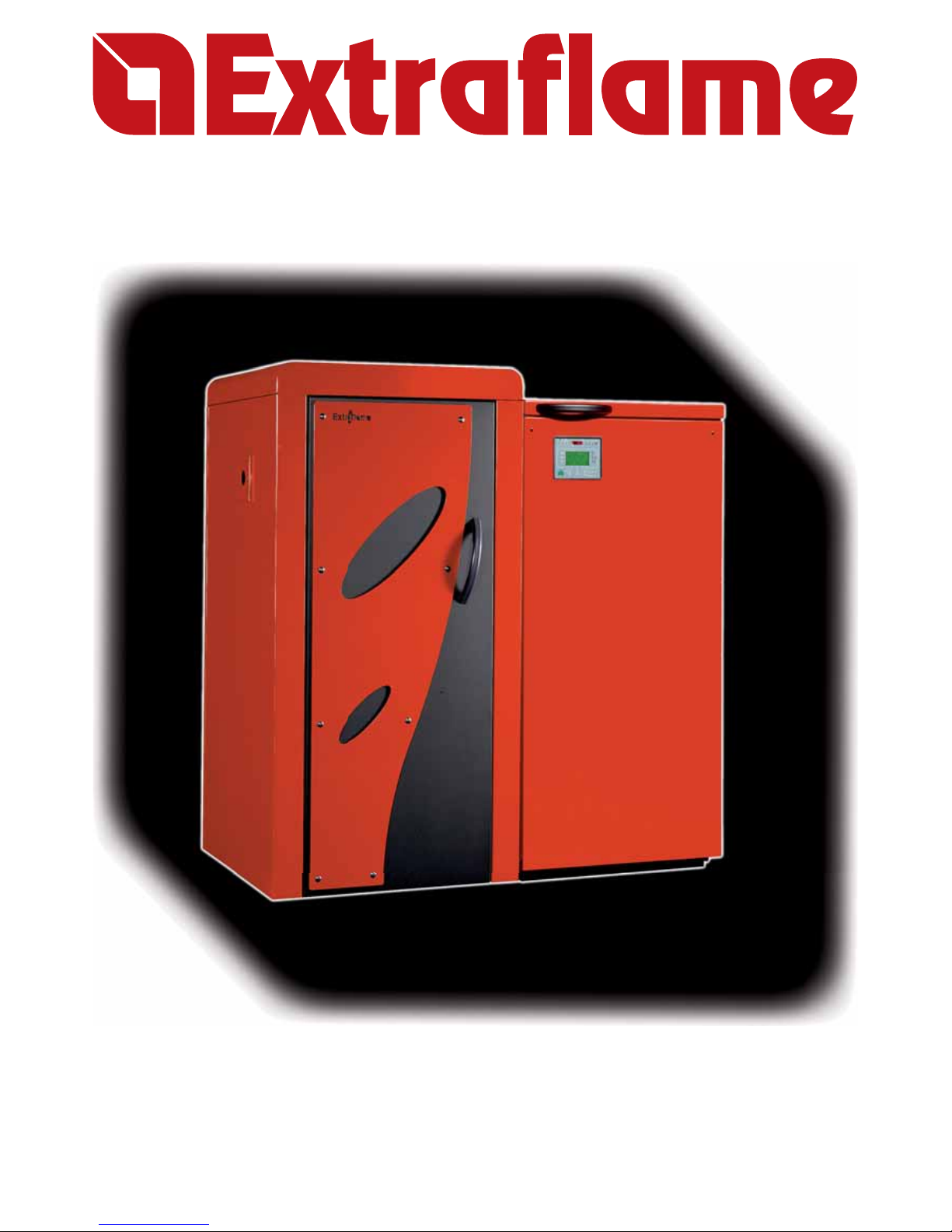
TERMOPELLET TP30
Read the instructions carefully before installation, use and maintenance.
The instruction book is an integral part of the product.
User manual
PELLET BOILERS
Page 2

2
Page 3

3
Congratulations! You are now the owner of an Extra ame boiler
The Extra ame boiler is a great heating solution developed from the most advanced technology with top
quality machining and modern design, aimed at making you enjoy the fantastic sensation that the heat of
a ame gives, in complete safety.
This manual will help you to use your boiler correctly. It must be read with great attention before use.
IMPORTANT
Make sure that your dealer lls the space in that is dedicated to your authorised specialist. He will help you
with pleasure if you should have problems using your new boiler.
AUTHORISED SPECIALIST
COMPANY __________________________________________________________________
Mr. ________________________________________________________________________
STREET NAME __________________________________________N°. __________________
POST CODE _____ TOWN/CITY _________________ COUNTY ______________________
TELEPHONE _________________________ FAX __________________________________
All Extra ame products are built in compliance with the following Directives:
89/106 EEC (Construction Products)
89/366 EEC (EMC Directive)
2004/108 CE (EMC Directive)
2006/95 CE (Low Voltage Directive)
and the Standards:
EN 60335-1
EN 60335-2-102
EN 61000-3-2
EN 61000-3-3
EN 50366
EN 55014-1
EN 55014-2
EN 303-5
Page 4

4
Page 5

5
Index
Chapter 1
WARNINGS AND SAFETY DEVICES.......................................................................................................... 7
Chapter 2
TECHNICAL FEATURES ............................................................................................................................. 9
Chapter 3
THE FUEL ..................................................................................................................................................12
THE PELLETS ........................................................................................................................................................................... 12
PELLET FEEDING ............................................................................................................................................................12
PELLET FEED ADJUSTMENT ......................................................................................................................................13
Chapter 4
BOILER ADJUSTMENT ............................................................................................................................14
SELECT THE DESIRED LANGUAGE .................................................................................................................................. 14
CURRENT DATE AND TIME SETTING .............................................................................................................................15
C.HEAT. CONFIGURAT .......................................................................................................................................................... 15
TRAPDOOR ACTIVATION TIME SETTING ..................................................................................................................... 16
SELECTION OF FUNCTIONING MODE .......................................................................................................................... 17
DESIRED TEMPERATURES SETTING ...............................................................................................................................17
Chapter 5
SWITCHON AND FUNCTIONING CYCLE ...............................................................................................19
Chapter 6
CHRONO SET MENU ................................................................................................................................21
Chapter 7
VARIOUS BOILER FUNCTIONS ............................................................................................................... 24
CHECKUP ................................................................................................................................................................................ 24
PUMPS ANTIFREEZE CYCLE ............................................................................................................................................ 24
PLANT ANTIFREEZE CYCLE .............................................................................................................................................. 24
SAFETY AREA 1 ...................................................................................................................................................................... 24
ANTIBACTER CYCLE ............................................................................................................................................................. 24
Chapter 8
SAFETY DEVICES ..................................................................................................................................... 25
FLUE EXHAUST BREAKAGE ............................................................................................................................................... 25
PELLET FEED MOTOR BREAKAGE ................................................................................................................................... 25
NO IGNITION...........................................................................................................................................................................25
TEMPORARY POWER CUT ................................................................................................................................................. 25
ELECTRIC SAFETY .................................................................................................................................................................25
PELLET TEMPERATURE SAFETY DEVICE .....................................................................................................................25
PELLET PIPE THERMAL SAFETY ...................................................................................................................................... 25
MECHANICAL SAFETY WITH FIRECUT ROTARY VALVE ......................................................................................... 25
DOOR OPENING SAFETY DEVICE ................................................................................................................................... 25
WATER BOILING SAFETY DEVICE .................................................................................................................................... 26
SAFETY DEVICES FOR OPEN VESSEL PLANT .............................................................................................................. 26
SAFETY DEVICES FOR CLOSED VESSEL PLANT ......................................................................................................... 26
MOUNTING OF HEAT DISCHARGE VALVE NOT SUPPLIED ................................................................................. 27
AUTOMATIC THERMOSTATIC VALVE .............................................................................................................................. 28
INSTALLATION AND SAFETY DEVICES ......................................................................................................................... 28
Page 6

6
Chapter 9
BOILER CLEANING ................................................................................................................................. 29
DAILY CLEANING ................................................................................................................................................................... 29
TWOMONTHLY CLEANING ............................................................................................................................................. 30
WEEKLY CLEANING .............................................................................................................................................................. 30
Chapter 10
BOILER DISPLAY TABLES ........................................................................................................................ 31
Chapter 11
WARRAN TY ..............................................................................................................................................37
Page 7

WARNINGS AND SAFETY DEVICES
7
Chapter 1
WARNINGS AND SAFETY DEVICES
INTRODUCTION
The boilers produced by our establishment are built with attention to the individual components in a
way to protect both the user and the installer from any accidents. It is therefore recommended that after
any intervention on the product, that authorised sta pay particular attention to the electric connections,
especially the stripped parts of the wires. These must not escape from the terminal board in any situation,
thus preventing possible contact with the live parts of the wire.
The instruction manual is an integral part of the product: make sure that it always accompanies the
appliance, even if transferred to other owners or user or is transferred to another place. If it is damaged or
lost, request another copy from the area technician.
This boiler must be destined for the use for which it has been expressly realised. The manufacturer is
exempt from any liability, contractual and extracontractual, for injury/damage caused to persons/animals
and objects, due to installation, adjustment and maintenance errors and improper use.
INSTALLATION
Installation of the boiler and auxiliary equipment in relation to the heating system must comply with all
current Standards and Regulations and to those envisioned by the law. Installation must be carried out
by authorised sta , who must provide the buyer with a declaration of conformity for the system and will
assume full responsibility for nal installation and as a consequence the correct functioning of the installed
product.
It is necessary to bear in mind all laws and national, regional, provincial and town council normatives
present in the country the appliance has been installed.
Extra ameS.p.A. cannot be held responsible for the failure to comply with such precautions. Before
installation, wash the pipes of the system well in order to remove any residues that could compromise the
correct functioning of the appliance. During installation, inform the user regarding:
a. In case of water leaks, he must close the water supply and promptly warn the after-sales technical
service.
b. The system working pressure must be checked periodically. If the boiler is not used for a long period of
time, it is recommended that the after-sales technical service is contacted to carry out at least the following
operations:
- Position the master switch on position 0.
- Close the water taps of both the heat system and the domestic hot water system;
- Empty the heating system and the domestic hot water system if there is risk of freezing.
COMMISSIONING
After the packaging has been removed, check the integrity and completeness of the contents.
If this does not comply, contact the dealer where the appliance was purchased.
During commissioning of the product, check the correct functioning of all devices, both safety and control,
which make up the boiler. All electrical components that make up the boiler must be replaced with original
spare parts exclusively by an authorised after-sales centre, thus guaranteeing correct functioning.
Before leaving the system, the sta in charge of commissioning must check boiler functioning for at least
one complete work cycle. The boiler must be serviced at least once a year, programming it in advance with
the technical after-sales service.
Page 8

WARNINGS AND SAFETY DEVICES
8
Chapter 1
APPROVALS
The Extra ame boilers have been designed and realised in compliance with the following Directives:
UNI EN 303-5 Boilers for central heating. Boilers for solid fuel, with manual and automatic feeding,
with a nominal heat output up to 300 kW
Compliance with the Low Voltage Directive (73/23 EEC)
Compliance with the EMC Directive (Electromagnetic compatibility 89/336 EEC)
FOR SAFETY
The boiler must not be used by children or unassisted disabled persons.
Do not touch the boiler when you are barefoot or when parts of the body are wet or humid.
The safety and adjustment devices must not be modi ed without the authorisation or indications of
the manufacturer.
Do not pull, disconnect, twist electric cables leaving the boiler, even if disconnected from the electric
power supply mains.
Do not close or reduce the dimensions of the airing vents in the place of installation.
The airing vents are indispensable for correct combustion.
Do not leave the packaging elements within reach of children or unassisted disabled persons.
The hearth door must always be closed during normal functioning of the product.
Avoid direct contact with parts of the appliance that tend to heat up during functioning.
Check for the presence of any obstructions before switching the appliance on following a prolonged
standstill period.
The boiler has been designed to function in any climatic condition (also critical). In particularly adverse
conditions (strong wind, freezing) safety systems may intervene that switch the boiler o .
If this occurs, contact the technical after-sales service and always disable the safety system.
If the ue should catch re, be equipped with suitable systems for su ocating the ames or request
help from the re service.
If the boiler should block, indicated by a signal on the display and that is not relative to lack of routine
maintenance, contact the technical after-sales centre.
USE
These boilers must be used to heat water to a temperature that does not exceed boiling point in the
conditions of installation.
Page 9

TECHNICAL FEATURES
9
Chapter 2
TECHNICAL FEATURES
Features
Unit of
Measurement
Value
Boiler class / 3
Introduced global heat output kW 33.0
Max. useful heat output kW 29.6
Min. useful heat output kW 9.3
Yield % > 89
Hourly fuel consumption kg/h 2.1 - 6.9
Flue gas temperature at max. useful heat output °C ~ 180
Flue gas temperature at min. useful heat output °C ~ 80
Flue gas ow rate at max. useful heat output kg/s 0.018
Flue gas ow rate at min. useful heat output kg/s 0.007
Chimney depression Pa 11
Maximum hydraulic pressure MPa 0,3
Water side head loss (17°C)
kPa 1.57 (1200 l/h)
kPa 5.54 (2500 l/h)
Water temperature adjustment °C 65 - 80
Water return to boiler minimum temperature* °C 55
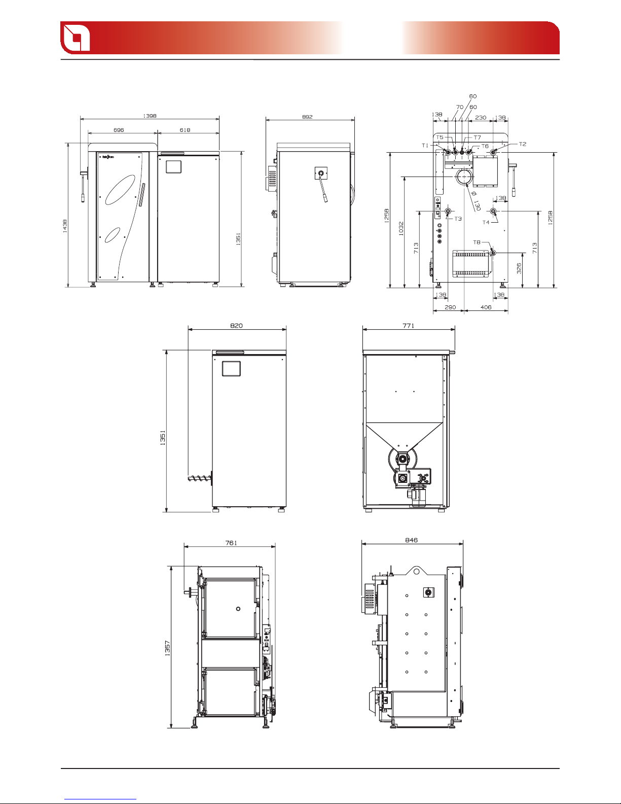
Boiler external dimensions mm (HxLxP) 1438 x 696 x 847
Pellet tank external dimensions mm (HxLxP) 1351 x 618 x 720
Boiler with pellet tank external dimensions mm (HxLxP) 1438 x 1320 x 847
Loading hatch dimensions mm 580 x 660
Empty boiler weight kg 415
Empty pellet tank weight kg 100
Boiler water volume l 65
Pellet tank capacity l - kg 260 - 180
Smoke exhaust diameter mm 130
Maximum electric power absorbed in the pellet ignition phase W 800
Thermal safety valve features (water)
°C < 20
MPa > 0,15
The boilers are managed by a circuit board with microprocessor with a lambda probe that corrects boiler
functioning anomalies by means of constant analysis of the exhaust gases.
The data obtained from the combustion tests have been realised using the following fuels:
ONORM M7 135 DIN PLUS Pellets.
* Realise a suitable anti-condensate circuit in a way to guarantee a minimum water temperature returning
to the boiler that is equal tot he value indicated (see “SAFETY DEVICES” chapter”).
Page 10
TECHNICAL FEATURES
10
Chapter 2
gure 2.1
Page 11
TECHNICAL FEATURES
11
Chapter 2
Pellet feeding
Automatic pellet ignition
Self-adjusting combustion system and automatic
cleaning by means of lambda probe
Automatic dispensing of the primary and secondary
air ow rate
Preparation for external storage silo
Cleaning device for the external ue gas pass
Draught for modulating intake with control via
encoder of the ue gas intake speed
Pellet insertion controlled by safety re-cut rotary
valve
Complete management via microprocessor
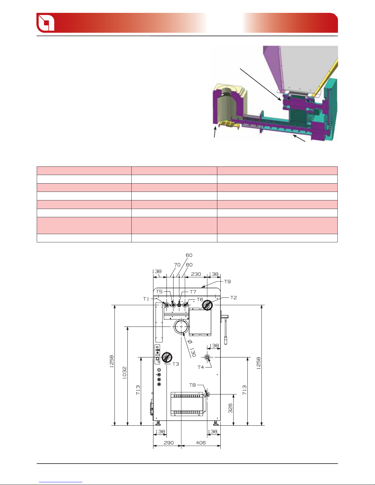
REFERENCE FITTINGS DIAMETER FITTINGS FUNCTION
T1 1” Heating ow
T2 1” Fitting blocked - do not use
T3 1” Fitting blocked - do not use
T4 1” Heating return
T5 = T6 3/4” D.S.A. Safety exchanger attachments
T7 1/2”
Safety heat exchanger probe sump
connection
T8 3/4” Boiler water drain
Rotary valve
re-cut
Brazier in
refractory material
Loading screw
for pellets
gure 2.2
gure 2.3
Page 12
THE FUEL
12
Chapter 3
THE FUEL
THE PELLETS
Pellets are realised by subjecting wood shavings i.e. the rejects of pure wood (without paint) sawmill,
carpenter products and products from other activities connected to working and transforming wood, to
very high pressures.
This type of fuel is absolutely ecological as no glues are used to hold it together. In fact, the compactness of
the pellets is guaranteed through time by a natural substance that is found in wood: lignite As well as being
an ecological fuel, as wood residues are made the most of, the pellet also has technical advantages.
Pellet density is 650 kg/m and water content equal to 8% of its weight. For this reason it is not necessary
to age the pellet to obtain a su ciently adequate heat yield (on the contrary, wood has 15% humidity after
about 18 months’ ageing).
To guarantee combustion without problems, the pellets must be kept in a dry place. The diameter goes
from a minimum of 5mm to a maximum of 8mm. Extra ame recommends using 6mm pellet.
PELLET FEEDING
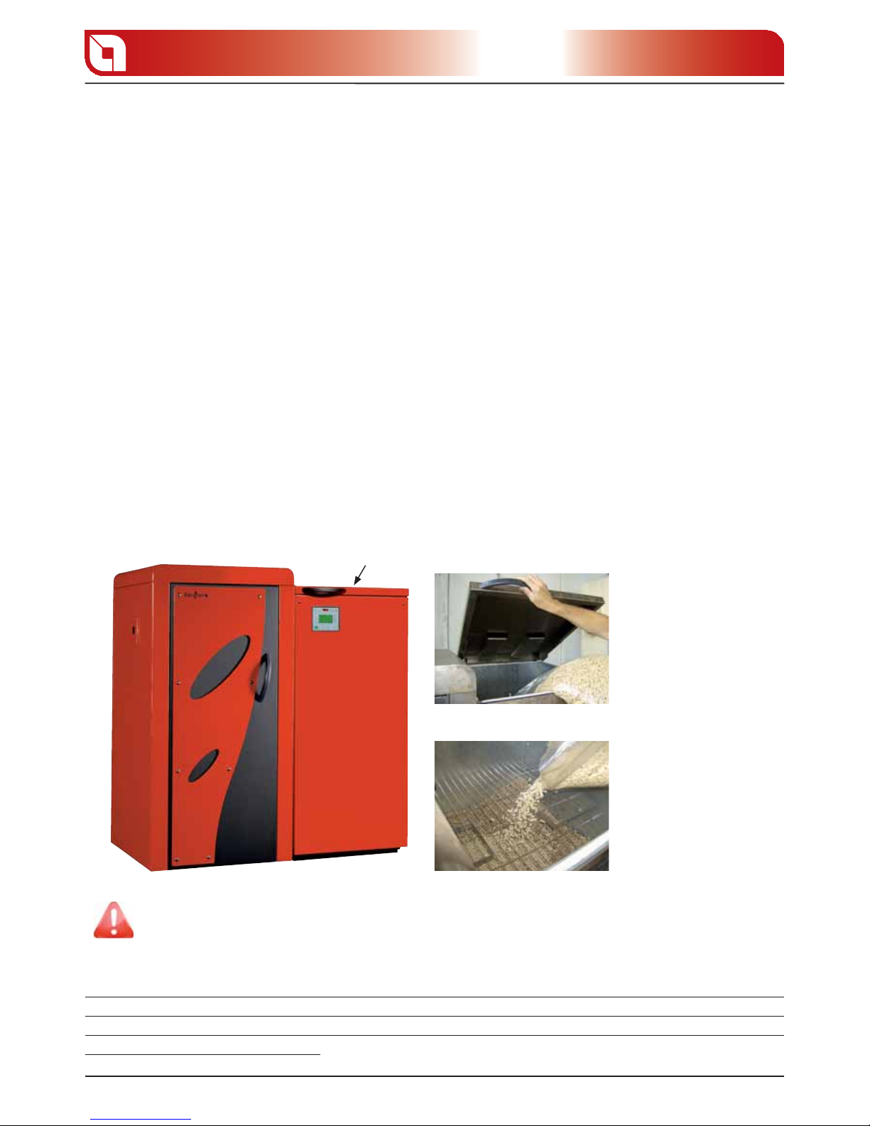
During rst product use, feed the pellet inside the tank, as illustrated in the gure, until completely full.
Pellet tank
1. Open the tank lid
2. Empty pellet inside the
tank
It is important to periodically check the residue pellet inside the tank to avoid it nishing
completely, which results in the boiler switching o .
WARNINGS
The use of expired pellets or any other unsuitable material can damage certain boiler components and
jeopardise its correct functioning: this can determine the invalidity of the warranty and the relative
responsibility of the manufacturer. Extra ame invites the user to use pellet in compliance with the described
features and the Standards in force.
gure 3.1
gure 3.2
gure 3.3
Page 13

THE FUEL
13
Chapter 3
PELLET FEED ADJUSTMENT
The pellet used must comply with the features described by the Standard:
Ö-Norm M 7135
DIN plus 51731
UNI CEN/TS 14961
* Extra ame recommends using pellet with 6 mm diameter.
Using pellet with features di erent to those listed above or for the features of the smokes evacuation plant,
it is possible that the boiler presents alterations respect to its optimal functioning.
If the problem occurs after only a few months working, check that routine cleaning stated
in the boiler booklet, has been carried out correctly.
The boiler is equipped with an adjustment system which intervenes directly on the pellet ow inside the
burner, optimising the combustion process. There can be 2 types of problems correlated to the amount of
fuel: lack of fuel or excess fuel.
Lack of fuel D the pellet is burnt too quickly, preventing the formation of a homogenous base inside the
burner. The boiler may not be able to develop the declared power.
Excess fuel D the pellet is not burnt completely, continuing to build up inside the burner. The boiler may
excessively overheat or create blocking problems.
The regulation to be performed is a percentage. Therefore a modi cation of this parameter will lead to a
proportional variation of all boiler feeding speeds.
Controls procedure:
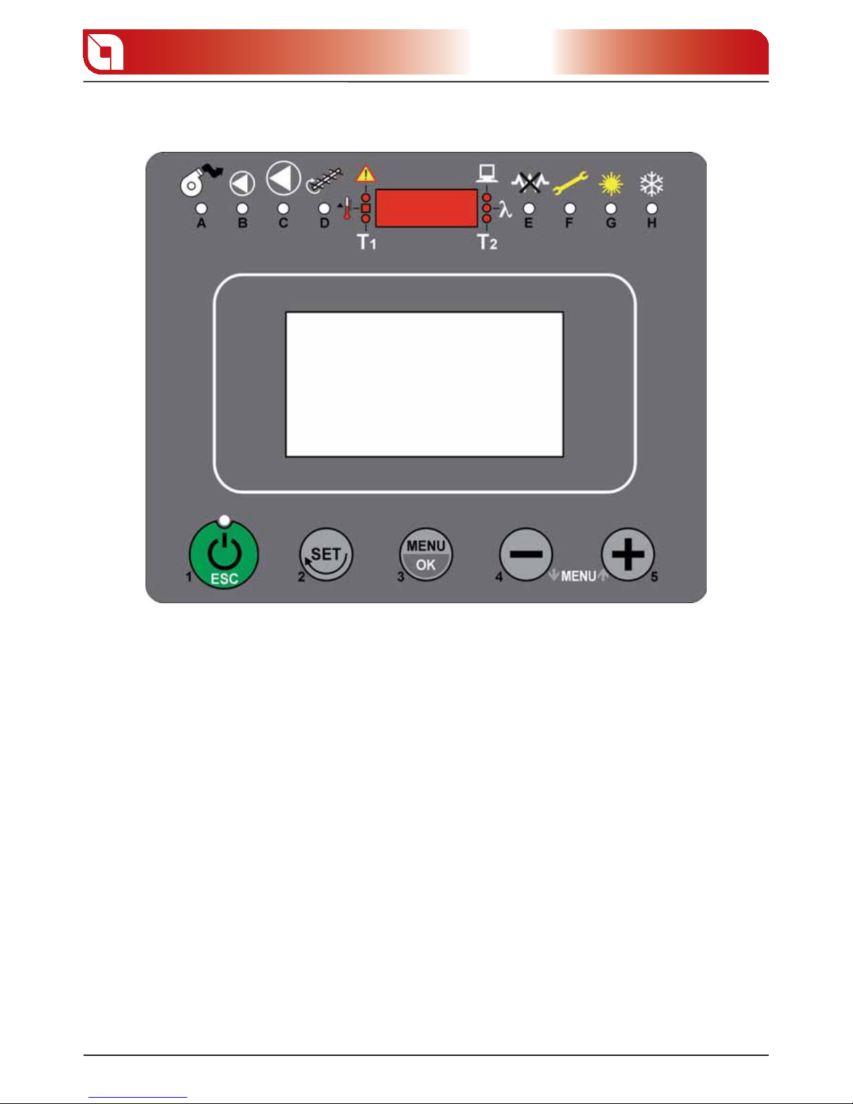
Press key 3 (menu/ok) to access the menu.
Press key 3 (menu/ok) to access the “ USER MENU”.
Select “ PELLET ADJUSTMENT MENU” using buttons 4(-) and 5(+) and press key 3 (menu/ok) to
con rm.
The value “00” will appear on the display: keys 4(-) and 5(+) can be used to adjust the percentage increase/
decrease desired by 5 points per time (the parameter can be varied with a maximum travel from –50 to
+50).
Increase/decrease the percentage value by 5 points and try the boiler with the new calibration for at least
2 hours.
If combustion improves but is not yet optimal, act as previously for a further 5 points. Repeat the
operation until the problem is solved.
If combustion worsens, act in reverse order in the adjustment.
When the adjustment has been made, press button 1(esc) to con rm and escape.
Page 14
BOILER ADJUSTMENT
14
Chapter 4
BOILER ADJUSTMENT
Before igniting the boiler, it is necessary to set certain parameters by means of the control board.
SELECT THE DESIRED LANGUAGE
In this section it is possible to select the desired language amongst those available:
ITALIANO
ENGLISH
FRANCAIS
DEUTSCH
Controls procedure:
Press key 3 (menu/ok) to access the menu.
Press key 3 (menu/ok) to access the “ USER MENU”.
Select “ LANG. MENU” using buttons 4(-) and 5(+) and press key 3 (menu/ok) to con rm.
Using buttons 4(-) and 5(+) select the desired language.
Press button 1(esc) to con rm and escape.
gure 4.1
Page 15

BOILER ADJUSTMENT
15
Chapter 4
CURRENT DATE AND TIME SETTING
Inside this menu it is possible to set the current day, hours and minutes.
Controls procedure:
Press key 3 (menu/ok) to access the menu.
Press key 3 (menu/ok) to access the “ USER MENU”.
Select “ CLOCK SET MENU” using buttons 4(-) and 5(+) and press key 3 (menu/ok) to con rm.
CLOCK SET 1 MENU D DAY CLOCK
Allows to use buttons 4(-) and 5(+) to set the current day that ashes (Monday - Tuesday).
To con rm and continue programming, press button 3 (menu/ok).
Press button 1 to escape (esc).
CLOCK SET 2 MENU D HOURS CLOCK
Allows to use buttons 4(-) and 5(+) to set the current hours ( ashing).
To con rm and continue programming, press button 3 (menu/ok).
Press button 2 (set) to go back to the previous parameter.
Press button 1 to escape (esc).
CLOCK SET 3 MENU D MINUTES CLOCK
Allows to use buttons 4(-) and 5(+) to set the current hours ( ashing).
To con rm and continue programming, press button 3 (menu/ok).
Press button 2 (set) to go back to the previous parameter.
Press button 1 to escape (esc).
C.HEAT. CONFIGURAT
The Extra ame boilers have the possibility to manage di erent external devices through the circuit board.
One of these devices can be a gas boiler which is de ned as an auxiliary boiler (AUX C.HEAT). It is called
auxiliary as its functioning is managed by the circuit board of the biomass boiler or due to an exact choice
on behalf of the user or due to a block of various nature (fuel exhaustion, an alarm, a manual or automatic
switch-o given by the weekly programmer).
The boiler con guration allows to choose in which way to use the auxiliary boiler.
There are 3 possible settings:
BIOMASS C.HEAT
BIOMASS / AUX
AUX C.HEAT.
BIOMASS C.HEAT: Only the biomass boiler works with this con guration.
BIOMASS/AUX: With this con guration, the biomass boiler always has priority with respect to the auxiliary
boiler. If for any reason (fuel exhaustion, any alarm except for HIGH WATER TEMP etc) the biomass boiler
blocks and cannot restart its normal functioning, the auxiliary boiler is activated. The biomass boiler circuit
board will supply power to the auxiliary boiler and will decide ignition/switch-o of the latter depending on
the requests analysed by the various devices in the plant and connected to the circuit board (e.g. domestic
Page 16

BOILER ADJUSTMENT
16
Chapter 4
hot water storage, pu er, etc.).
The ignition of the auxiliary boiler is always delayed by about 20 minutes.
Once the biomass boiler functioning is restores, the electronic board will again exclude the auxiliary boiler
functioning. By switching o the biomass boiler through key 1, the auxiliary boiler is also switched o .
AUX. C. HEAT.: With this con guration, the biomass boiler remains o but powered. In this way, the
biomass boiler circuit board can supply power to the auxiliary boiler and will decide ignition/switch-o of
the latter depending on the requests analysed by the various devices in the plant and connected to the
circuit board (e.g. domestic hot water storage, pu er, etc.).
If the boiler is on and set at BIOMASS C.HEAT or BIOMASS/AUX, after having set AUX C.HEAT switch the
biomass boiler o using button 1 to start functioning of the auxiliary boiler.
The ignition of the auxiliary boiler is always delayed by about 20 minutes.
To switch the auxiliary boiler o , act directly on the master switch of the same or set the BIOMASS C.HEAT
or BIOMASS/AUX.
Controls procedure:
Press key 3 (menu/ok) to access the menu.
Press key 3 (menu/ok) to access the “ USER MENU”.
Select “ C.HEAT. CONFIGURAT” using buttons 4(-) and 5(+) and press key 3 (menu/ok) to con rm.
Using buttons 4(-) and 5(+) select the desired setting.
Press button 1(esc) to con rm and escape.
TRAPDOOR ACTIVATION TIME SETTING
The boiler is provided with an automatic cleaning system which foresees the opening of a metal trapdoor
at the base of the pellet combustion brazier. It is necessary to choose a time span in which this cleaning is
active and consequently exclude it for the times of day in which such cleaning is not indispensable.
N.B. It is not possible to completely exclude the automatic cleaning.
Controls procedure:
Press key 3 (menu/ok) to access the menu.
Press key 3 (menu/ok) to access the “ USER MENU”.
Select “ C.HEAT. CONFIGURAT” using buttons 4(-) and 5(+) and press key 3 (menu/ok) to con rm.
Press button 3 (menu/ok) again to access the trapdoor activation setting.
TRAPDOOR START TIME
Allows to use buttons 4(-) and 5(+) to set the start time of the active trapdoor phase.
To con rm and continue programming, press button 3 (menu/ok).
To go back to C.HEAT. CONFIGURAT press button 2(set).
Press button 1 to escape (esc).
Page 17

BOILER ADJUSTMENT
17
Chapter 4
TRAPDOOR STOP TIME
Allows to use buttons 4(-) and 5(+) to set the end time of the active trapdoor phase.
To con rm and continue programming, press button 3 (menu/ok).
Press button 2 (set) to go back to the previous parameter.
Press button 1 to escape (esc).
Exclusion of cleaning for several hours can lead to trapdoor blocking.
SELECTION OF FUNCTIONING MODE
In this section it is possible to select 2 di erent boiler functionings:
WINTER
SUMMER
To select the desired functioning, use buttons 4(-) and 5(+).
Press button 1(esc) to con rm and escape the menu.
WINTER: in this functioning mode all devices present in the plant work regularly. The priority given to the
devices is the following:
DOMESTIC HOT WATER STORAGE1.
HEATING PLANT (Radiators)2.
PUFFER3.
SUMMER: in this functioning mode the room thermostats relative to the heating plant (radiators) are
always satis ed: this means that the circuit board will never enable the circulation pumps (zone 1 and
zone 2) relative to the heating plant except for the safety functions (if the temperature of the water inside
the boiler exceeds 90°C, the pump in zone 1 is activated in order to remove the excess heat).
The following priority is kept for the remaining devices:
DOMESTIC HOT WATER STORAGE1.
Controls procedure:
Press key 3 (menu/ok) to access the menu.
Press key 3 (menu/ok) to access the “ USER MENU”.
Select “ SUMMER-WINTER MENU” using buttons 4(-) and 5(+) and press key 3 (menu/ok) to con rm.
Using buttons 4(-) and 5(+) select the desired functioning.
Press button 1(esc) to con rm and escape
DESIRED TEMPERATURES SETTING
The boiler allows to set the desired water temperature in di erent points of the plant.
There are 3 settings to adjust:
C.H. SET
BOILER SET
ECONOMY SET
Page 18

BOILER ADJUSTMENT
18
Chapter 4
C.H. SET D allows to set the desired water temperature inside the boiler.
The set can be set from a minimum value of 65°C to a maximum of 80°C or the automatic mode can
be selected. Setting a value between 65°C and 80°C, the boiler works to reach the desired temperature
decreasing the functioning power once nearing the set; if the temperature exceeds the set by at least 5°C
(c.h. set + 5°C) the boiler switches o displaying “HOFF” on the display and will wait for re-ignition until
the temperature has not decreased by at least 5°C below the set threshold (c.h. set - 5°C).
The automatic function can only be activated after having connected and enabled the probe
positioned outside the building. These operations must be carried out by authorised sta .
After having connected and enabled the external probe, to activate the function it is necessary to adjust
the boiler set below 65°C: “AUTO” will appear in the top left of the display.
In automatic mode, the ch. set adjusts automatically depending on the temperature read by the EXTERN.
probe (temperature outside the building): it has a maximum travel reading from +20 to -10°C which
correspond to the boiler setting details from 65 to 80°C (ex. If the external temperature is -10°C the
temperature set automatically sets at 80°C).
To move on to the subsequent setting press button 5.
In the case of request by the domestic hot water storage tank or the pu er, the temperature of
the water inside the boiler can exceed the boiler set in order to satisfy the request quickly
BOILER SET D allows to set the desired water temperature inside an external domestic hot water storage
tank. The setting goes from a minimum value of 45 to a maximum value of 70 °C.
To move on to the subsequent setting press button 5(+).
ECONOMY SET D allows to set an economy threshold for the re-ignition of the boiler. This function
becomes operative when the boiler is in an HOFF state, that is, when the boiler water temperature exceeds
by at least 5°C the c.h. set. The setting goes from a minimum value of 30 to a maximum value of 60 °C or
OFF.
If the parameter is set on OFF the boiler will use the normal re-ignition set, that is, c.h. set – 5°C. If set with
a value between 30 and 60, the re-ignition will happen at that temperature and “ ECONOMY WAIT T.” will
be displayed on the display.
To con rm and escape press button 1(esc).
Controls procedure:
2(set) D access the temperature set
4(-) and 5(+) D select the temperature set to be adjusted amongst those available:
C.H. SET
BOILER SET
ECONOMY SET
3(menu/ok) D access the selected set
4(-) and 5(+) D adjust the selected set
1(esc) D con rm and escape
Page 19

SWITCHON AND FUNCTIONING CYCLE
19
Chapter 5
SWITCHON AND FUNCTIONING CYCLE
Before switching the boiler on the following points must be veri ed:
the combustion chamber must be free and clean.
The burners must be completely free and clean.
Check hermetic closure of the re doors.
Check that the power supply cable is connected correctly.
The bipolar switch in the rear part must be positioned on 1.
Check for the presence of pellets in the tank.
Before every 0/1 switch-on the check-up must appear.
Press button 1(esc) for 3 seconds: “1. START” will be displayed on the display. In this phase, the
appliance cleans the burner through a shaking of the mobile grate positioned on the bottom..
Following, the boiler will pass to “2. IGNITION”: in this phase the appliance loads the pellets inside
the burner to trigger the combustion process. If at the end of the second cycle the boiler has not
developed a ame “NO FLAME ALARM” will appear on the display. In this case press button 1(esc) for
3 seconds until the display shows “FINAL CLEANING”, remove and re-apply current from the master
switch and repeat steps 1 and 2.
If the alarm appears several times consecutively, contact the after-sales service.
The rst time the product is used, even if the tank is full of pellets, there is the possibility that
during the rst ignition cycle the pellets are not fed. This is because the pellet feed worm screw
is empty. If at the end of the rst cycle the boiler has not yet developed a ame, this will re-start
from the START phase.
If points 1 and 2 have been carried out correctly, the moment the boiler develops the ame, the 3.
boiler will pass to “BURNING”, ame settling phase before starting work.
Completed the start phase, the boiler will pass to “4. WORKING” phase, where the boiler will heat the
water inside to satisfy the heat requirements deriving from the plant.
The boiler works varying on 5 di erent power levels which cannot be adjusted as the adjustment
is automatic in relation to the set temperature set.
During the work phase the boiler works to reach the desired temperature decreasing the 5.
functioning power once nearing the set; if the temperature exceeds the set by at least 5°C (c.h. set +
5°C) the boiler switches o displaying “HOFF” (automatic switch-o ) and will wait for re-ignition until
the temperature has not decreased by at least 5°C below the set threshold (c.h. set - 5°C).
In the case of a request by the domestic hot water storage tank or the pu er, the boiler
uses di erent sets with respect to that set by the user.
The last phase is the switch-o , which can be realised through manual control, button 1(esc) for 3 seconds,
or through the weekly programmer.
The display shows “OFF” and the boiler stops de nitely when completely cooled o .
Button 4(-) allows to display the value read by the various probes which can be connected to the boiler.
Page 20

SWITCHON AND FUNCTIONING CYCLE
20
Chapter 5
Press button 4(-) once Press button 4(-) twice
EXTERN. UPP. PUFFER
BOILER/EXCHANGER LOW. PUFFER
FLUE T. INT. SPEED
LAMBDA PROBE AUX C.HEAT.
The value read by the probes can be replaced with other digits:
D probe excluded
SHORT D closed contact or short circuit
OPEN D open contact or probe disconnected
To escape the probe reading press any button.
Button 5(+) allows to display the state of all inputs and outputs of the electronic board.
This menu is reserved to the Extra ame S.p.A. after-sales assistance.
To escape the probe reading press any button.
Page 21

CHRONO SET MENU
21
Chapter 6
CHRONO SET MENU
Controls procedure:
Press key 3 (menu/ok) to access the menu.
Press key 3 (menu/ok) to access the “ USER MENU”.
Select “ CHRONO SET MENU” using buttons 4(-) and 5(+) and press key 3 (menu/ok) to con rm.
The boiler is equipped with a weekly programmer which allows to program 3 time spans within a day to
use every day of the week. The ignition and switch-o times must be within the arc of one day, from 0 to
24 and not over several days:
E.g. switch-on 07:00 / switch-o 18:00 OK
switch-on 22:00 / switch-o 05:00 ERROR
switch-on 22:00 / switch-o 23:59 OK
PARAMETER FUNCTION
KEYS
ADJUSTMENT
DISPLAY
CONFIRMATION
KEY
CHRONO ONOFF
Act./deact. weekly programmer 4(-) o 5(+) ON/OFF 3(menù/ok)
START PROGRAM 1
Time 1st switch-on 4(-) o 5(+) OFF or from 00:00 to 23:50 3(menù/ok)
STOP PROGRAM 1
Time 1st switch-o 4(-) o 5(+) OFF or from 00:00 to 23:50 3(menù/ok)
DAYS ON 1
Consents for 1st switch on/o for various days
4(-) o 5(+) ON/OFF Monday ... ON/OFF Sunday 3(menù/ok)
START PROGRAM 2
Time 2nd switch-on 4(-) o 5(+) OFF or from 00:00 to 23:50 3(menù/ok)
STOP PROGRAM 2
Time 2nd switch-o 4(-) o 5(+) OFF or from 00:00 to 23:50 3(menù/ok)
DAYS ON 2
Consents for 2nd switch on/o for various days
4(-) o 5(+) ON/OFF Monday ... ON/OFF Sunday 3(menù/ok)
START PROGRAM 3
Time 3rd switch-on 4(-) o 5(+) OFF or from 00:00 to 23:50 3(menù/ok)
STOP PROGRAM 3
Time 3rd switch-o 4(-) o 5(+) OFF or from 00:00 to 23:50 3(menù/ok)
DAYS ON 3
Consents for 3rd switch on/o for various days
4(-) o 5(+) ON/OFF Monday ... ON/OFF Sunday 1(esc)
Let’s suppose that the weekly programmer function is to be used and 3 time periods are to be used in the
following way:
1st time span: from 08:00 to 12:00 every day of the week excluding Saturday and Sunday
2nd time span: from 15:00 to 22:00 only Saturday and Sunday
3rd time span: not used
Let’s set the weekly programmer.
CHRONO ON-OFF
Use buttons 4(-) or 5(+) to activate the weekly programmer by setting the value at ON.
To con rm and continue programming, press button 3 (menu/ok).
START PROGRAM 1
Use buttons 4 or 3 to set “08:00”, which corresponds to the switch-on time of the 1st time span.
To con rm and continue programming, press button 3 (menu/ok).
Press button 2 (set) to go back to the previous parameter.
STOP PROGRAM 1
Use buttons 4(-) or 5(+) to set “12:00”, which corresponds to the switch-on time of the 1st time span. To
con rm and continue programming, press button 3 (menu/ok).
Press button 2 (set) to go back to the previous parameter.
Page 22

CHRONO SET MENU
22
Chapter 6
DAYS ON 1
Activate the rst time span for every day of the week except Saturday and Sunday.
To do this use keys 4(-) and 5(+) in the following way:
a. key 5(+) scroll the various days
b. key 4(-) enable/disable (ON/OFF) the 1st time span for that day
Example:
DAY
INITIAL
VALUE
KEY 4(-) FUNCTION FINAL VALUE KEY 5(+) FUNCTION
MONDAY OFF OFF Æ ON and vice-versa ON (time span active) Go to next day
TUESDAY OFF OFF Æ ON and vice-versa ON (time span active) Go to next day
WEDNESDAY OFF OFF Æ ON and vice-versa ON (time span active) Go to next day
THURSDAY OFF OFF Æ ON and vice-versa ON (time span active) Go to next day
FRIDAY OFF OFF Æ ON and vice-versa ON (time span active) Go to next day
SATURDAY OFF OFF Æ ON and vice-versa OFF (time deactivated) Go to next day
SUNDAY OFF OFF Æ ON and vice-versa OFF (time deactivated) Go to next day
To confi rm and continue programming, press button 3 (menu/ok).
Press button 2 (set) to go back to the previous parameter.
START PROGRAM 2
Use buttons 4(-) or 5(+) to set “15:00”, which corresponds to the switch-on time of the 2nd time span.
To con rm and continue programming, press button 3 (menu/ok).
Press button 2 (set) to go back to the previous parameter.
STOP PROGRAM 2
Use buttons 4(-) or 5(+) to set “22:00”, which corresponds to the switch-o time of the 2nd time span.
To con rm and continue programming, press button 3 (menu/ok).
Press button 2 (set) to go back to the previous parameter.
DAYS ON 2
Enable the 2nd time span only for Saturday and Sunday.
To do this use keys 4(-) and 5(+) in the following way:
a. key 5(+) scroll the various days
b. key 4(-) enable/disable (ON/OFF) the 1st time span for that day
Example:
DAY
INITIAL
VALUE
KEY 4(-) FUNCTION FINAL VALUE KEY 5(+) FUNCTION
MONDAY OFF OFF Æ ON and vice-versa OFF (time deactivated) Go to next day
TUESDAY OFF OFF Æ ON and vice-versa OFF (time deactivated) Go to next day
WEDNESDAY OFF OFF Æ ON and vice-versa OFF (time deactivated) Go to next day
THURSDAY OFF OFF Æ ON and vice-versa OFF (time deactivated) Go to next day
FRIDAY OFF OFF Æ ON and vice-versa OFF (time deactivated) Go to next day
SATURDAY OFF OFF Æ ON and vice-versa ON (time span active) Go to next day
SUNDAY OFF OFF Æ ON and vice-versa ON (time span active) Go to next day
To con rm and continue programming, press button 3 (menu/ok).
Press button 2 (set) to go back to the previous parameter.
Page 23

CHRONO SET MENU
23
Chapter 6
START PROGRAM 3
Set at “OFF” using buttons 4(-) or 5(+), which is found before the time “00:00”, in a way to disable the
switch-on of the 3rd time span.
To con rm and continue programming, press button 3 (menu/ok).
Press button 2 (set) to go back to the previous parameter.
STOP PROGRAM 3
Set at “OFF” using buttons 4(-) or 5(+), which is found before the time “00:00”, in a way to disable the
switch-o of the 3rd time span.
To con rm and continue programming, press button 3 (menu/ok).
Press button 2 (set) to go back to the previous parameter.
DAYS ON 3
At this point the values introduced in this parameter have no value as the ignition and switch-o of the 3rd
time span have been disabled.
Press button 1(esc) to con rm and escape the programming.
Press button 2 (set) to go back to the previous parameter.
Page 24

VARIOUS BOILER FUNCTIONS
24
Chapter 7
VARIOUS BOILER FUNCTIONS
CHECKUP
This function is carried out every time current is removed and re-applied from the boiler in the “OFF“
status. The check-up checks all the devices constituting the boiler.
PUMPS ANTIFREEZE CYCLE
This function avoids the plant water freezing when the boiler is switched o . When the temperature read
by some of the boiler probes falls below a determined temperature value the circuit board will activate all
of the outputs relative to the pumps/electro-thermal controls.
Pumps/electro-thermal controls will stop when the temperature rises.
PLANT ANTIFREEZE CYCLE
If the boiler anti-freeze function is not su cient to stop the lowering of the water, the system antifreeze function activates, which ignites the boiler. The boiler will remain switched on until a determined
temperature level has been reached.
SAFETY AREA 1
This function activates if the water temperature inside the boiler exceeds 87°C: even if there is no request
for heat, the electro-thermal pump/control relating to area 1 is enabled.
The stopping of the electro-thermal pump/controls will happen when the temperature decreases.
It is fundamental that the installer foresees the presence of an important heating area in the home (AREA
1) in which at least one radiator is never closed.
ANTIBACTER CYCLE
This function only activates with boiler on and allows to neutralise the bacteria of Legionnaire’s disease.
This bacteria in the water reacts di erently in relation to the water temperature:
Below 20°C the Legionnaire’s disease can live but in quiescence condition (it does not multiple but it
does not die).
Between 20 and 50°C the Legionnaire’s disease multiplies, with particularly high speed between 35
and 46°C, therefore right in the temperature area of normal domestic hot water use.
Between 50 and 55°C the Legionnaire’s disease can live but in lethargy condition (it does not multiple
but it does not die).
Between 55 and 60°C the Legionnaire’s disease is eliminated in about 6 hours.
Between 60 and 66°C the Legionnaire’s disease is eliminated in about 35 minutes.
Above 66°C the Legionnaire’s disease is eliminated in about 3 minutes.
To remedy this problem, if when the boiler is switched on the temperature of the water inside the domestic
storage is lower than 65°C for a period longer than 48 hours, the domestic storage water is heated (70°C for
at least 5 minutes) even in the absence of heat request, to neutralise the bacteria.
Page 25

SAFETY DEVICES
25
Chapter 8
SAFETY DEVICES
FLUE EXHAUST BREAKAGE
If the exhaust stops, the electronic board blocks the functioning and sends the boiler in alarm.
PELLET FEED MOTOR BREAKAGE
If the motor reducer stops, the boiler continues to function until the minimum cooling level is reached.
NO IGNITION
If a ame is not developed during the ignition phase, the appliance automatically attempts ignition
again.
If no ame develops also in this case, the appliance will signal ignition failure alarm on the display.
TEMPORARY POWER CUT
If the lack of current is lower than 10 seconds, the boiler ignores everything and starts its normal functioning
in the state it was in. If the time interval is higher than 10 seconds, the machine will display the “BLACK
OUT COOLING” alarm (see display table).
ELECTRIC SAFETY
The boiler is protected against strong current changes by a master fuse that is found in the rear part of the
boiler. (12.5 A 250V Delayed).
PELLET TEMPERATURE SAFETY DEVICE
If there is overheating inside the tank, this device blocks the pellet feed motor; restoration is manual and
must be performed by an authorised technician who will check the cause of the overheating.
PELLET PIPE THERMAL SAFETY
If the thermal sensor of the pellet pipe detects an increase in the temperature in the same pipe, it activates
a pipe cleaning cycle.
MECHANICAL SAFETY WITH FIRECUT ROTARY VALVE
At the base of the loading tank there is a re-cut rotary valve that prevents any ame propagation to the
pellet tank.
DOOR OPENING SAFETY DEVICE
The boiler doors must never be opened during functioning or when the boiler is still hot!! The opening of
the doors during functioning causes the boiler to block with the relative signal on the display.
Page 26
SAFETY DEVICES
26
Chapter 8
SAFETY DEVICES FOR OPEN VESSEL PLANT
According to the UNI 10412-2 (2006) Standard, the plants with open expansion vessel must have:
Open expansion vessel
Safety pipe
Feed pipe
Pump control thermostat (excluded for natural circulation plants)
Circulation system (excluded for natural circulation plants)
Acoustic alarm activation device
Acoustic alarm
Temperature indicator
Pressure indicator
Automatic circuit breaker switch (block thermostat)
The temperature safety sensors must be in place on the machine at a distance no greater than 30 cm from
the ow connection.
Whenever the generators lack a device, those missing can be installed on the thermo product ow pipe,
within a distance no greater than 1m from the machine.
SAFETY DEVICES FOR CLOSED VESSEL PLANT
According to the UNI 10412-2 Standard, the closed plants must have:
Safety valve
Pump control thermostat
Acoustic alarm activation thermostat
Temperature indicator
Pressure indicator
Acoustic alarm
Adjustment automatic circuit breaker switch
Automatic circuit breaker switch (block thermostat)
Circulation system
Expansion system
Safety dissipation system incorporated with the generator with thermal safety valve (self-activated),
whenever the appliance does not have a temperature self-adjustment system
WATER BOILING SAFETY DEVICE
In case there is scarce amount of water in the boiler
or insu cient heat absorption on behalf of the plant
due to circulation block, overheating until boiling
point of the same water may be caused. A manual
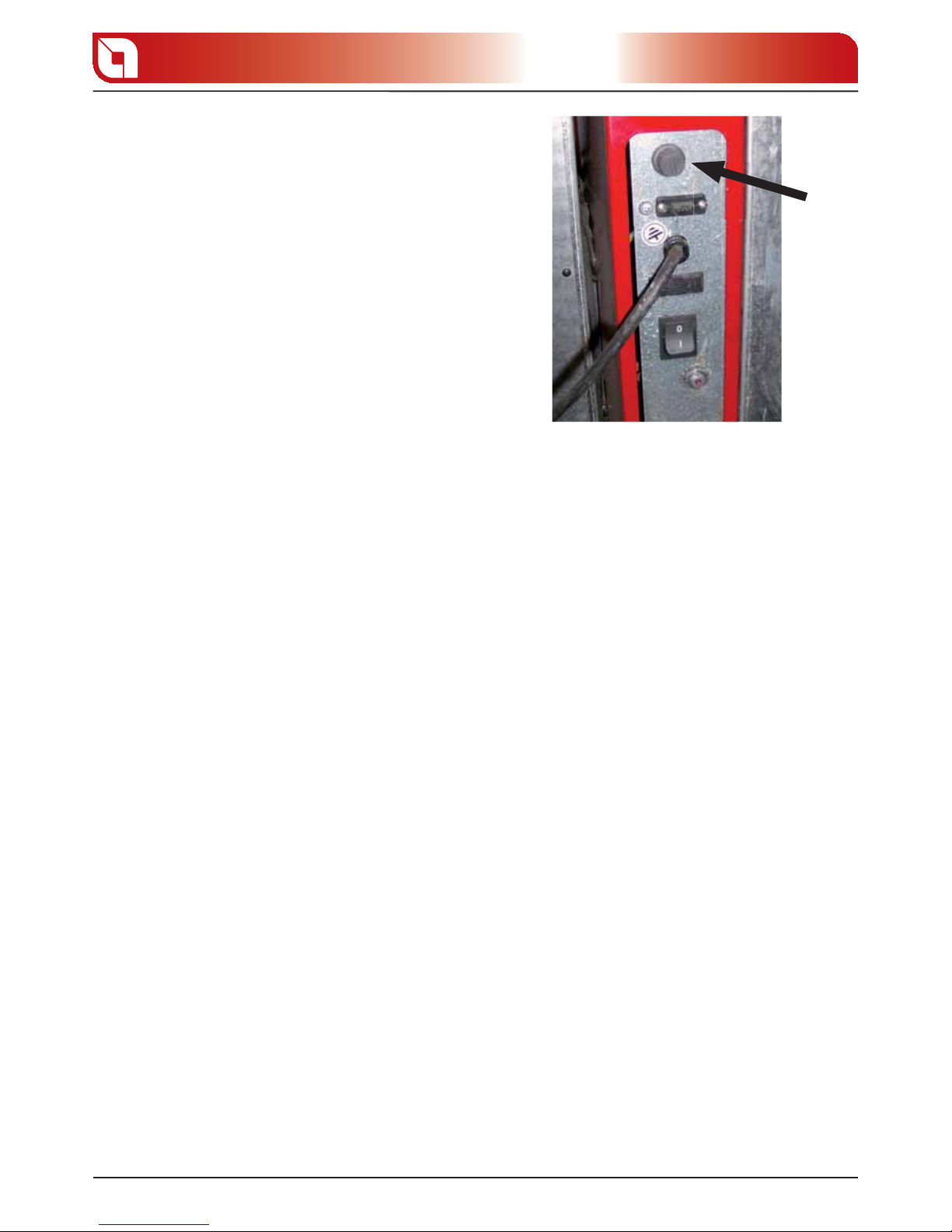
re-arm thermostat block the pellet feed motor. The
manual restoring of the thermostat is carried out by
pressing the buttons located at the rear of the boiler
and covered by screwable caps.
The intervention of the after-sales centre for boiler
over heating is not covered by warranty in case the
machine has not been connected to an adequate
storage, with volume of at least 1000 litres (see
“WARRANTY” chapter).
gure 8.1
Page 27
SAFETY DEVICES
27
Chapter 8
The temperature safety sensors must be in place on the machine at a distance no greater than 30 cm from
the ow connection.
Whenever the generators lack a device, those missing can be installed on the thermo product ow pipe,
within a distance no greater than 1m from the machine.
Domestic type heating appliances with automatic feed must have a fuel block thermostat or a cooling
circuit prepared by the manufacturer of the appliance, activated by a thermal safety valve such as to
guarantee that the limit temperature set by the Standard is not exceeded. Connection between the power
supply unit and the valve must be free from interceptions. The pressure upstream from the cooling circuit
must be at least 1.5 bar.
MOUNTING OF HEAT DISCHARGE VALVE NOT SUPPLIED
The solid fuel heat generators must be installed with safety devices determined by laws in force. With this
purpose the TP30 boiler has a safety heat exchanger as well as the block thermostat.
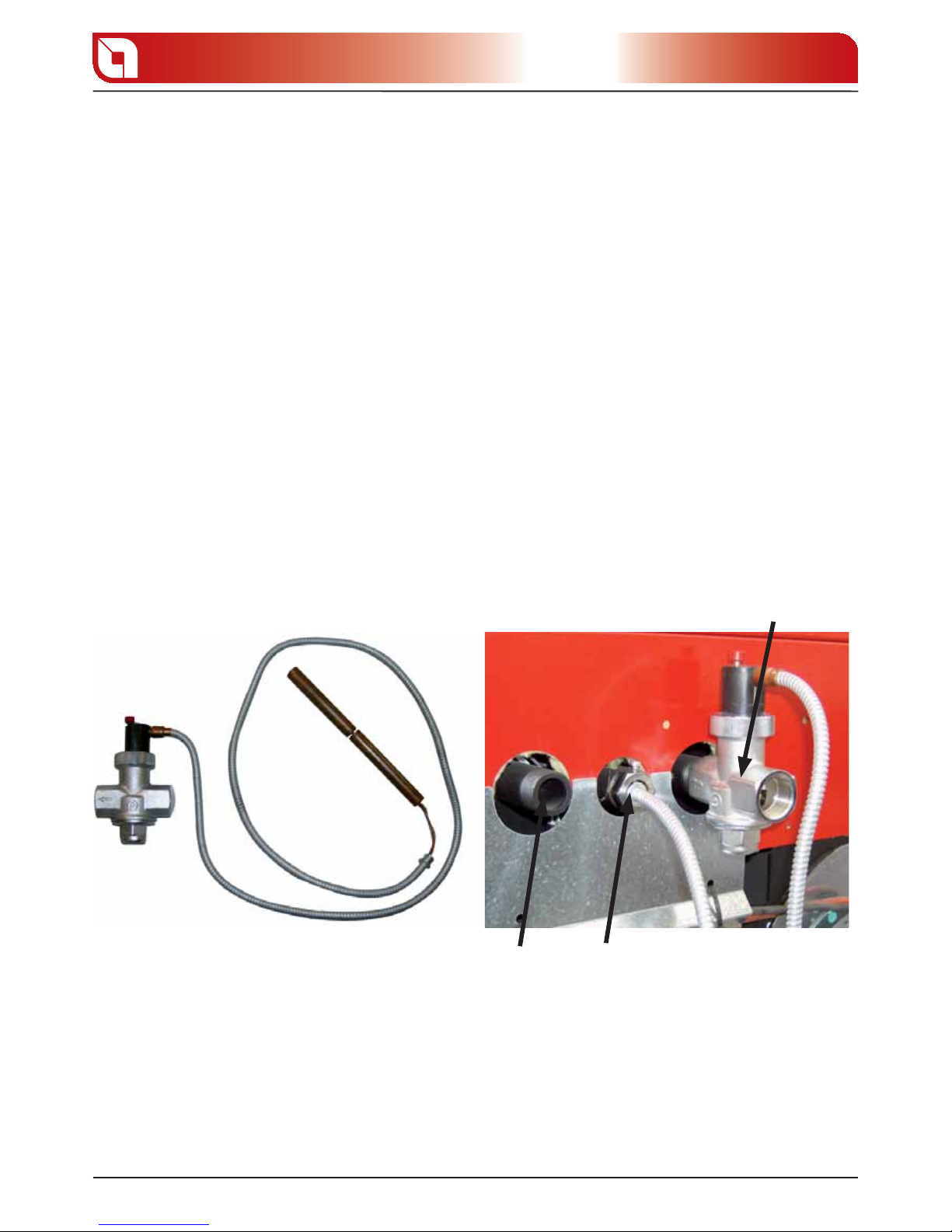
The safety exchanger must be connected on one side to the water network (A) and the other to
the drainage network (C). The heat discharge valve, whose bulb will be connected to attachment B, on
reaching the safety temperature enables the inlet of cold water into the copper coil contained in the
boiler, discharging the excess heat through the pipe C towards an appropriately installed drain.
A
B
C
gure 8.2
gure 8.3
Page 28
12
3
SAFETY DEVICES
28
Chapter 8
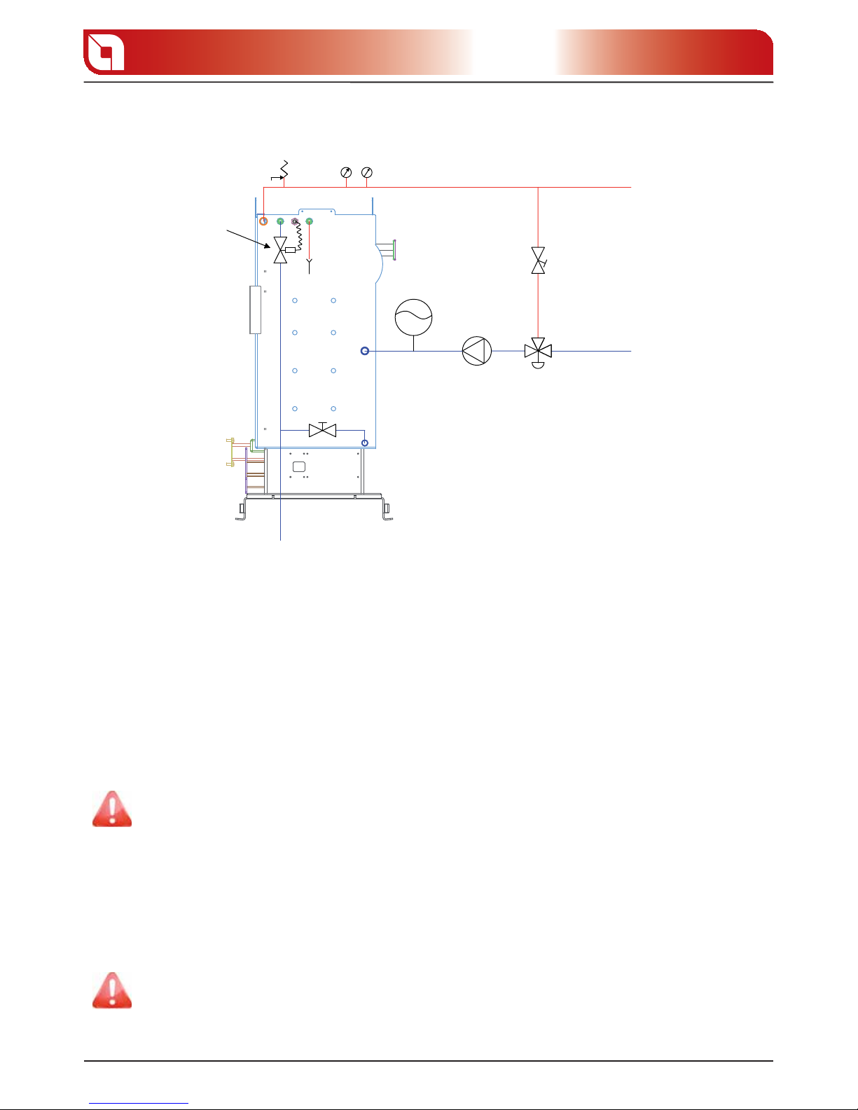
Thermal safety
valve 95° C
3 bar safety valve
Thermometer
Manometer
Flow
Balance
valve
Expansion
vessel
Pump
Return
Load
Network
Cooling circuit upstream pressure must be at least 1.5 bar.
AUTOMATIC THERMOSTATIC VALVE
The automatic thermostatic mixing valve nds applications in solid fuel boilers as it prevents cold water
return in the exchanger.
Routes 1 and 3 are always open and, together with the pump installed on the return (R), they guarantee
water circulation inside the biomass boiler exchanger.
An elevated return temperature, allows e ciency improvement, reduces formation of smoke condensation
and prolongs the boiler life span.
Valves on the market have di erent calibrations. Extra ame advises use of model 55°c with 1” hydraulic
connections. Once the valve calibration temperature is reached, route 2 is opened and the boiler water
goes to the system via the ow (M).
Lack of installation of the device voids the heat exchanger warranty (see “WARRANTY” chapter).
INSTALLATION AND SAFETY DEVICES
The installation and relative plant connections, commissioning and inspection of correct functioning must
be carried out perfectly by professionally authorised sta (Ministerial Decree 22 January 2008 n. 37), in
total compliance with Standards in force, both national and regional, as well as these instructions.
Extra ame S.p.A. declines all responsibility for damages to objects and/or persons caused by the plant.
gure 8.4
Page 29
BOILER CLEANING
29
Chapter 9
BOILER CLEANING
Before carrying out any maintenance operation, the boiler must be in “OFF” state and completely cold. At
this point, remove power supply to the boiler by directly acting on the rear switch.
Never discharge the water from the plant, even partially, in order to avoid mulfunctionings. Periodically
check the good functioning and integrity of the pipe and/or smoke exhaust device.
In case of work or maintenance of structures located near smoke pipes and/or smoke exhaust devices and
their accessories, switch o the appliance and, once completed work, have the e ciency checked out by
professionally quali ed sta .
Do not clean the boiler and/or its parts with easily ammable substances (ex. petrol, alcohol, etc).
Do not leave containers of ammable substances in the room where the boiler has been installed.
Do not clean the thermal control unit whilst the boiler is working.
At the end of every heating period, it is necessary for the boiler to be inspected by professionally quali ed
sta in order to maintain the plant perfectly e cient.
An accurate maintenance is reason for savings and safety, in fact the presence of soot and scales on the
exchange walls, reduce boiler e ciency and do not allow to maintain the declared performances. If the
power supply cable is damaged, it must be replaced by authorised after-sales assistance.
DAILY CLEANING
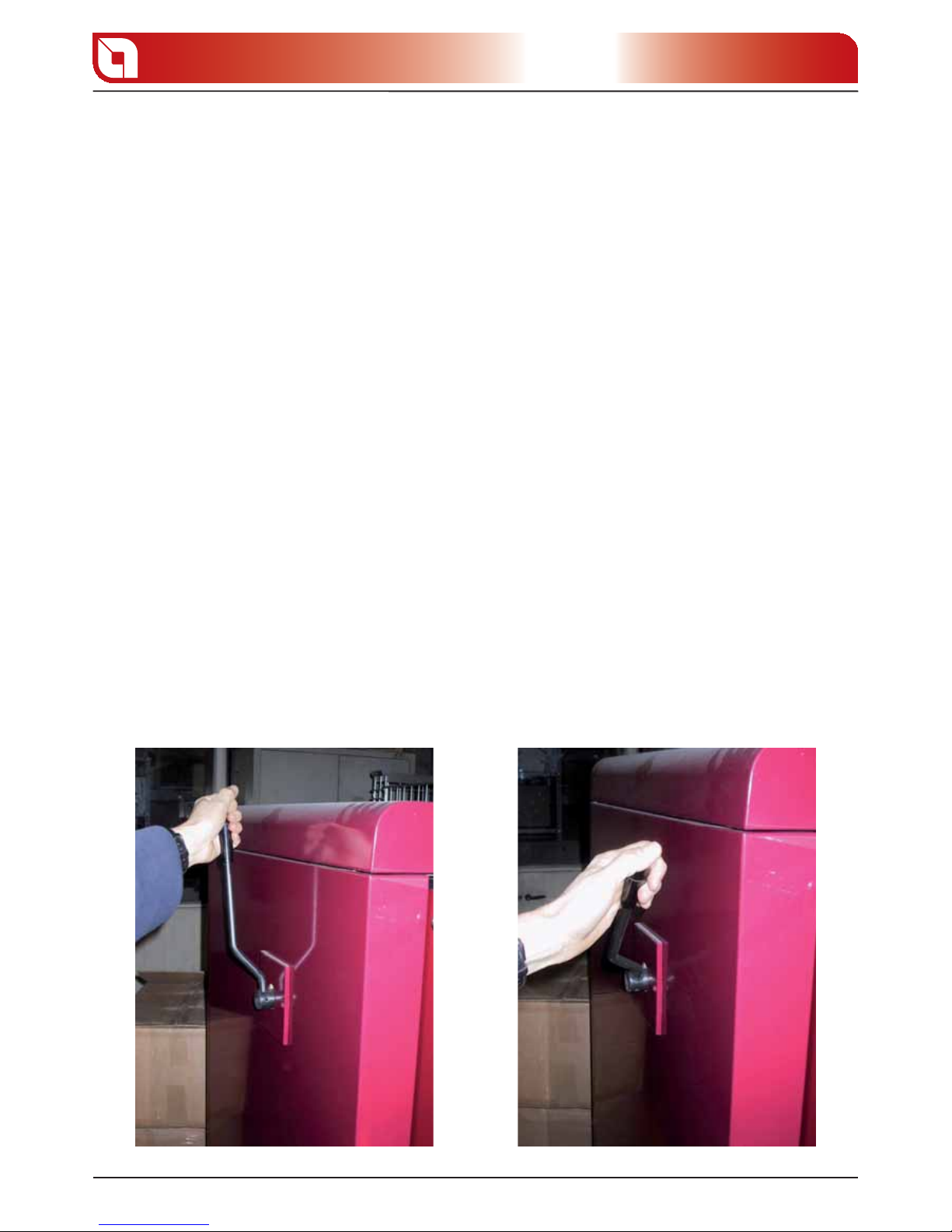
The use of the lever located on the left side of the boiler, guarantees good functioning of the same avoiding
the forming of layers of ash which opposes to the normal turning of smoke.
For this reason Extra ame recommends to repeat the movement indicated in the gures below at least 4/5
times a day.
gure 9.1 gure 9.2
Page 30
BOILER CLEANING
30
Chapter 9
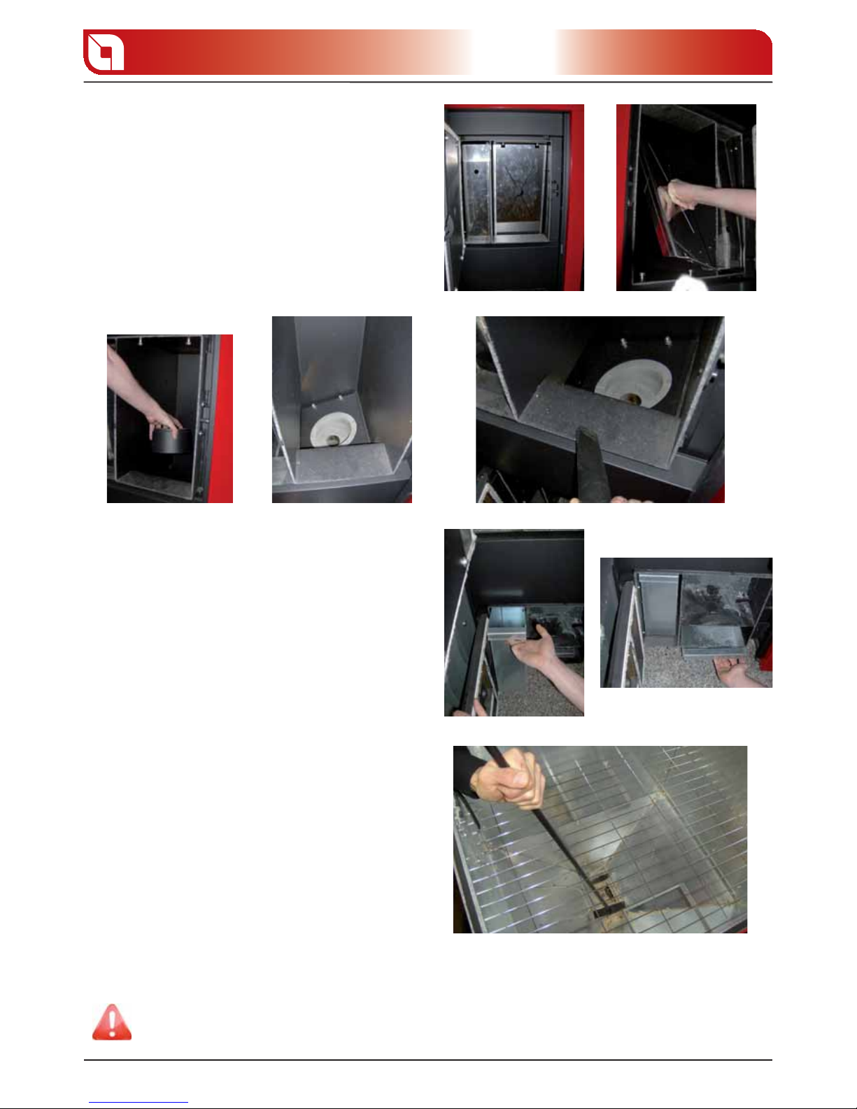
WEEKLY CLEANING
Every week it is necessary to open the re door
to remove the ash that has deposited around
the burner completely (see gure at the side).
Every week it is also necessary to open the two
lower drawers ( gure at the side) and empty
them from the accumulated ash.
TWOMONTHLY CLEANING
Completely empty the pellet tank and using
the scraper, remove the residue wood shavings
deposited near the rotary valve, as indicated in the
gure at the side.
For correct functioning, the boiler must undergo routine maintenance by an authorised
technician, at least once a year.
gure 9.3 gure 9.4
gure 9.5 gure 9.6 gure 9.7
gure 9.8 gure 9.9
gure 9.10
Page 31
BOILER DISPLAY TABLES
31
Chapter 10
BOILER DISPLAY TABLES
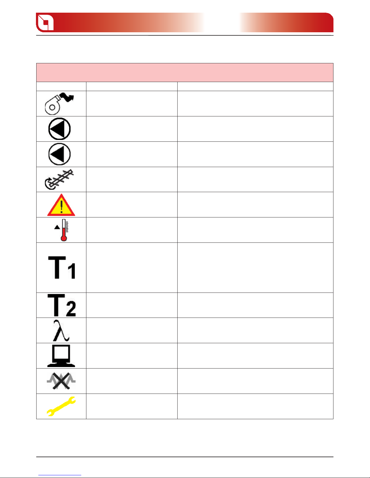
LUMINOUS INDICATORS
Indicators Description Explanation
A
It indicates functioning of the fumes
expulsion motor.
It is on/o when the fumes exhaust motor is activated/deactivated.
It ashes when the speed control probe (encoder) is disconnected.
B
Indicates the consent for pump
functioning.
It is on/o to indicate functioning consent/dissent for the circulation
pump.
C
Indicates the consent for pump/external
electro-thermal controls functioning.
It is on/o to indicate functioning consent/dissent for the external
electro-thermal pumps/controls.
D
It indicates functioning of the pellet feed
motor.
It is on/o when the pellet feed motor is activated/deactivated.
The indicator switches on intermittently during normal functioning as
the motor works with impulses.
Indicates the presence of an alarm.
It is on in the presence of an alarm and is accompanied by the relative
signal in the display, which identi es the cause. To reset the alarm, just
hold key 1(esc) down for 3 seconds when the boiler is completely cold.
Not used Preparation for future applications
Indicates the status of zone 1 thermostat.
The indicator is on/o when the external thermostat has to be satis ed/
dissatis ed. If to be satis ed, i.e. heat request, activate the relative pump/
electro-thermal control for the circulation of water.
The activation of this pump/electro-thermal control takes place also if
the temperature of the water inside the boiler exceeds 87°C (overheating
safety device).
In this case the pump/electro-thermal control stops when the
temperature of the water falls below 85°C.
Indicates the status of zone 2 thermostat.
The indicator is on/o when the external thermostat has to be satis ed/
dissatis ed. If to be satis ed, i.e. heat request, activate the relative pump/
electro-thermal control for the circulation of water.
Indicates the functioning of the lambda
probe.
The indicator is on/o when the lambda probe is activated/deactivated.
Indicates the status of the serial port.
The indicator is on/o when the serial communication with the electronic
board is disabled/enabled.
Indicates deactivation of the ign-plug for
automatic ignition.
It is o /on when the electrode is activated/deactivated.
Not used Preparation for future applications
Page 32
BOILER DISPLAY TABLES
32
Chapter 10
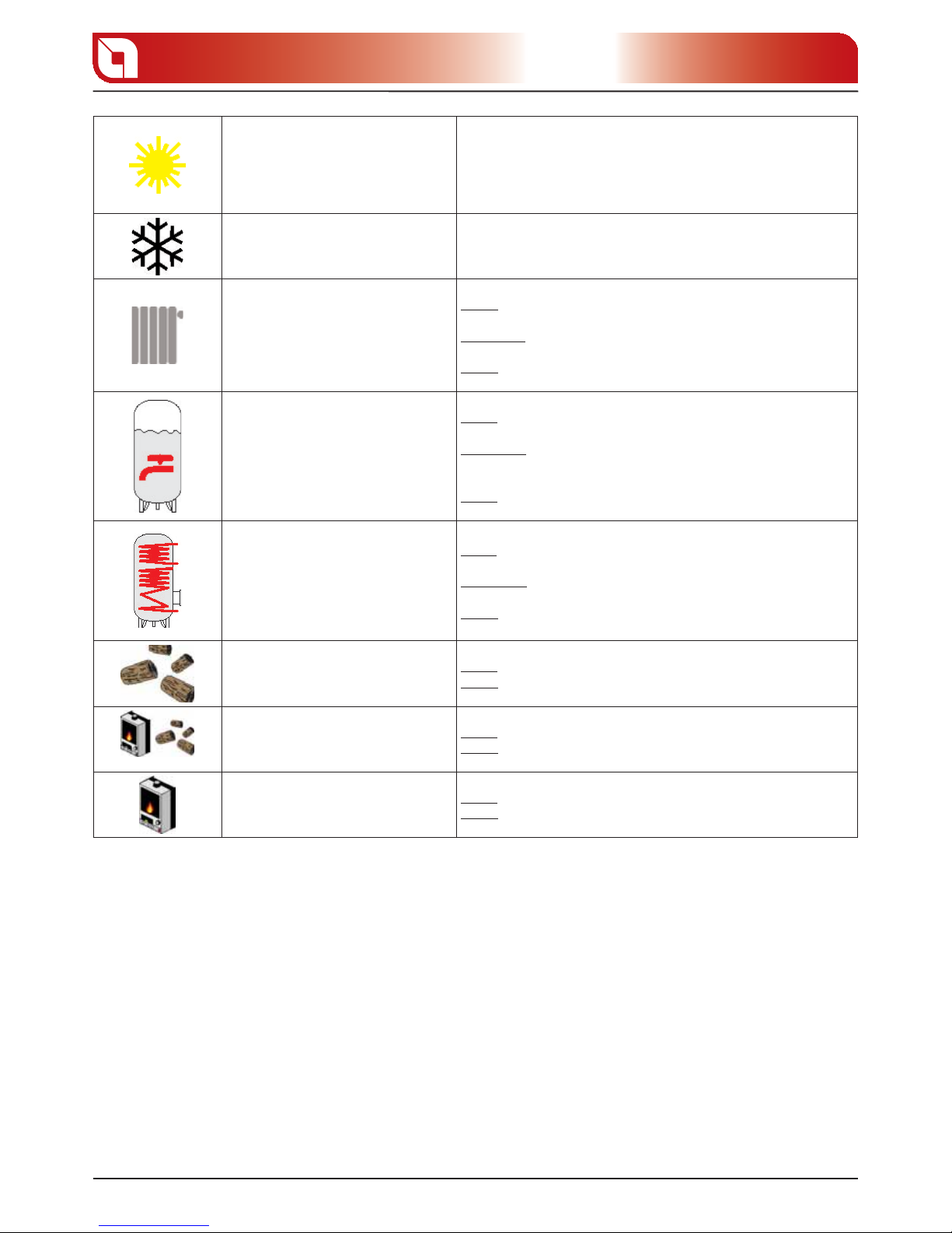
Indicates the SUMMER mode.
In this functioning mode the room thermostats relative to the heating
plant (radiators) are always satis ed: this means that the circuit board
will never enable the pumps (zone 1 and zone 2) relative to the heating
plant except for the safety functions (if the temperature of the water
inside the boiler exceeds 87°C, the pump in zone 1 is activated in order
to remove the excess heat).
Indicates the WINTER mode. In this functioning mode all devices present in the plant work regularly.
Indicates the request for heat by the
heating system.
There are 3 possible indications:
Dot o : There is no request for heat by thermostats T1 and T2; pumps/
electro-thermal controls are o :
Flashing dot: There is a request for heat by thermostats T1 and T2; pumps/
electro-thermal controls are o as work conditions are not satis ed.
Dot on: There is a request for heat by thermostats T1 and T2; pumps/
electro-thermal controls are on:
Indicates the request for heat by the
sanitary storage.
There are 3 possible indications:
Dot o : There is no request for heat by sanitary storage; pumps/electrothermal controls are o :
Flashing dot: There is a request for heat by thermostats sanitary storage;
pumps/electro-thermal controls are o as work conditions are not
satis ed.
Dot on: There is a request for heat by sanitary storage; pumps/electrothermal controls are on:
Indicates the request for heat by the
pu er.
There are 3 possible indications:
Dot o : There is no request for heat by the pu er; pumps/electro-thermal
controls are o :
Flashing dot: There is a request for heat by the pu er; pumps/electrothermal controls are o as work conditions are not satis ed.
Dot on: There is request for heat by the pu er; pumps/electro-thermal
controls are on:
Indicates setting
BIOMASS C.HEAT.
There are 2 possible indications:
Dot o : This setting has not been selected.
Dot on: This setting has been selected and the C.Heat. is in a work or
stand-by status for automatic re-ignition.
Indicates setting
BIOMASS / AUX.
There are 2 possible indications:
Dot o : This setting has not been selected.
Dot on: This setting has been selected and the C.Heat. is in a work or
stand-by status for automatic re-ignition.
Indicates setting
AUX C.HEAT.
There are 2 possible indications:
Dot o : This setting has not been selected.
Dot on: This setting has been selected and the C.Heat. is in a work or
stand-by status for automatic re-ignition.
Page 33

BOILER DISPLAY TABLES
33
Chapter 10
DISPLAYS
Display Description Explanation
IGNITION
Indicates the pellet ignition phase Phase in which pellet combustion is triggered
PUMP ANTILOCK
Indicates the function that prevents pump
block.
This function activates every 48 hours by activating all plant
pumps/electro-thermal controls.
SYSTEM ANTIFREEZE
Indicates the system anti-freeze function.
If the C.H. anti-freeze function is not su cient to stop the lowering
of the water temperature, the system anti-freeze function
activates, which ignites the C.H. The C.H. and the pump/electrothermal controls will stay on until they reach a determined
temperature level.
PUMP ANTIFREEZE
Indicates the pump anti-freeze function.
If the temperature read by some of the C.H. probes falls below a
determined temperature value the circuit board will activate all
of the outputs relative to the pumps/electro-thermal controls.
Pumps/electro-thermal controls will stop when the temperature
rises.
WAIT FOR CLEAN.
A new ignition is attempted when the boiler
has just been switched o (normal switch-o
or caused by an alarm).
When the stove switches o (normal or caused by an alarm) it is
necessary to wait until it cools down completely, therefore clean
the brazier. Leave the boiler completely o and cold for at least
15 minutes before switching it on again.
ECONOMY T. WAIT
The C.Heat. is in “HOFF” status and the
ECONOMY SET has been set
The re-ignition of the C.H. is restricted by the temperature set in
the
ECONOMY SET.
START
Indicates the pellet combustion phase. Indicates the transition phase between ignition and working.
CHECKUP
Indicates the control function performed by
the boiler.
This function activates every time current is removed and reapplied from the boiler in the
OFF, status. The machine performs
a particular analysis cycle to check the correct functioning of al
of its parts.
ANTIBACTER. CYCLE
Indicates the antibacter. function.
This function only activates with boiler on and allows to neutralise
the bacteria of Legionnaire’s disease.
CORRECTION O2
Indicates the combustion correction
function.
This functioning cycle uses the value read by the lambda probe
in order to correct imperfect combustion. At the end of the
correction cycle the boiler will go back to normal functioning
HOFF
The temperature of the water has exceeded
the set threshold by more than 5°C.
The water has reached a temperature of
85°C.
On lowering of the water temperature (5° below the set threshold)
the machine will re-start in automatic mode.
WORKING
Indicates the normal functioning status of
the boiler
The boiler works to satisfy the plant requests.
OFF
Indicates the o status of the boiler
In this status the boiler is completely cold and waiting to be
ignited; this can take place in di erent ways in relation to the
boiler setting used.
LOWER DOOR OPEN
The lower door is open Check closure of the lower door
CONDUIT CLEANING
Indicates the pellet load conduit cleaning
function caused by a temperature increase
inside the conduit
Wait for the complete conduit cleaning cycle until the boiler
returns to normal functioning. If this is not the case, the C.H. will
display the “
PELLET CONDUIT ALARM “
AUTOMATIC
CLEANING
Indicates the boiler automatic cleaning
function
This function envisions a complete cleaning cycle that includes
switch o and switch on of the boiler.
FINAL CLEANING
The boiler was switched o through button
1(esc)
At the end of this cleaning and cooling cycle the boiler will pass
to the
OFF status
COOLING BLACK OUT
No current on the main power supply for a
period longer than 10 seconds
After the complete switch-o cycle the stove will re-ignite
automatically
SAFETY Z1
Indicates the safety for removal of heat
accumulated in the boiler
This function activates if the water temperature inside the boiler
exceeds 87°C: the pump/electro-thermal control relative to zone
1 is enabled even if there is no request for heat. Stop occurs when
the temperature drops
AUTO BLOW
Indicates the burner automatic blow
function
The burner automatic blow is accompanied by the on the display.
At the end of the cleaning cycle the boiler will go back to normal
functioning
COR. PEL.
Indicates a high temperature on the fumes
It is not in alarm conditions. The C.H. intervenes automatically to
lower the temperature level, continuing its normal work
Page 34

BOILER DISPLAY TABLES
34
Chapter 10
START
Indicates the preparation phase for boiler
ignition.
The boiler must be set in wood/pellet mode.
From the
OFF status by pressing key 1(esc) this preparation
phase is engaged for boiler ignition.
TIMER XX XXX
Timer reserved to the Extra ame after-sales
dept.
Timer reserved to the Extra ame after-sales dept.
Page 35

BOILER DISPLAY TABLES
35
Chapter 10
ALARMS
Display Reason Solution
CONDUIT ALARM
PELLET
Indicates overheating of the pellet
feed conduit.
In the case of pellet loading conduit overheating the boiler initially
intervenes by starting the “CONDUIT CLEANING” cycle. If this is
not su cient, after a period of about 10 minutes the boiler will block,
showing “
PELLET CONDUIT ALARM”” on the display.
During this alarm, do not:
Open the upper door
Open the lower door
Open the pellet tank lid
At this point re-attempt the ignition phase: if the alarm remains blocked
on the display not allowing any operation, it means that the conduit
is not cool enough. Wait for the complete cooling of the conduit and
repeat the ignition phase.
TRAPDOOR BLOCK
ALARM
Indicates a positioning error of the
burner cleaning trapdoor.
Switch o the machine, wait for complete cooling and repeat the
ignition cycle.
If the problem persists, the restoration operations must be carried
out by an authorised technician.
OXYGEN KO
KO ALARM
Error detected by the lambda probe
on lack of oxygen for combustion.
Lambda probe connection or power
supply problems.
Check that the pellet used is in compliance with the features described
in “THE FUEL” chapter.
Progressively reduce the pellet ow (see “PELLET ADJUST MENU”).
Switch o the machine, wait for complete cooling and repeat the
ignition cycle.
If the problem persists, the restoration operations must be carried
out by an authorised technician.
OPENED DOOR
ALARM
Indicates the opening of the lower
door during the working phase.
Close the door, switch o the machine, wait for complete cooling and
repeat the ignition cycle.
If the problem persists, the restoration operations must be carried
out by an authorised technician.
HIGH WATER TEMP.
ALARM WATER
Indicates excessive water
temperature.
Problems with water circulation.
Insu cient plant pressure.
Presence of air in the system.
Check the plant pressure.
Bleed the air from the plant.
Switch o the machine, wait for complete cooling and repeat the
ignition cycle.
If the problem persists, the restoration operations must be carried
out by an authorised technician.
NO FLAME
ALARM
The pellet feed-box is empty.
The upper and lower doors are not
closed correctly.
Problems relative to the ign-plug.
Air intake pipe problems.
Problems on the fumes expulsion
pipe.
The combustion chamber is dirty.
Pellet feed calibration inadequate.
Dusty wood residue in proximity of
the rotary valve that prevents the
ow of pellets.
Check for the presence of pellets in the feed-box.
Check hermetic closure of the doors.
Check that the air vent and the fumes exhaust are not blocked or
unsuitable.
Check cleanliness of the combustion chamber.
Check the procedures described in the “C.H. FUNCTIONING CYCLE”
chapter.
Adjust pellet ow (see “PELLET ADJUST MENU”).
Empty the feed-box completely and remove the dusty residue using
the irons-scraper.
Switch o the machine, wait for complete cooling and repeat the
ignition cycle.
If the problem persists, the restoration operations must be carried
out by an authorised technician.
FUMES FAN
ALARM
The fumes motor is blocked.
Speed control probe problems
(encoder).
Fumes motor power supply
problems.
Switch o the machine, wait for complete cooling and repeat the
ignition cycle.
If the problem persists, the restoration operations must be carried
out by an authorised technician.
Page 36

BOILER DISPLAY TABLES
36
Chapter 10
ELEV. FUMES
ALARM
Combustion chamber dirty.
Excessive pellet feed.
Gas probe reading/calibration error.
Fumes exhaust problem.
Air intake problem.
Clean the combustion chamber taking care to scrape the walls using
the scraper irons.
If the pellets used have a greater eating power with respect to that
declared and used by the company, reduce the ow of pellets (see
“PELLET ADJUSTMENT MENU”).
Check the presence of an air vent that respects the features stated in
the installer manual.
Switch o the machine, wait for complete cooling and repeat the
ignition cycle.
If the problem persists, the restoration operations must be carried
out by an authorised technician.
GAS PROBE KO
ALARM
The fumes probe is broken.
The fumes probe is disconnected
from the board.
Switch o the machine, wait for complete cooling and repeat the
ignition cycle.
If the problem persists, the restoration operations must be carried
out by an authorised technician.
PROBE KO
ALARM
Indicates a fault or incorrect
connection of one of the boiler
probes.
Switch o the machine, wait for complete cooling and repeat the
ignition cycle.
If the problem persists, the restoration operations must be carried
out by an authorised technician.
NO PELLET
ALARM
The pellet feed-box is empty.
The motor reducer does not feed
pellets.
Problems on the fumes expulsion
pipe.
Air intake pipe problems.
No pellet feed.
Dusty pellet residue in proximity of
the rotary valve that prevents ow.
Check for the presence of pellets in the feed-box.
Check that the air vent and the fumes exhaust are not inadequate.
Check that the combustion chamber is clean.
Adjust pellet ow (see “PELLET ADJUST MENU”).
Empty the feed-box completely and remove the dusty residue using
the irons-scraper.
Switch o the machine, wait for complete cooling and repeat the
ignition cycle.
If the problem persists, the restoration operations must be carried
out by an authorised technician.
LAMBDA BROKEN
Lambda probe broken, detected
during C.H. check-up.
Switch o the machine, wait for complete cooling and repeat the
ignition cycle.
If the problem persists, the restoration operations must be carried
out by an authorised technician.
THERMAL SECURITY
ALARM
Problem correlated to the bulb
thermostats inside the boiler (feedbox 85°C and hot water 100°C).
Check the plant pressure: if vessel is closed, adjust system pressure to
1.2 bar.
Bleed the air from the plant.
Check the presence and the correct installation of the anti-condensate
thermostatic mixer valve.
Only when the cause has been identi ed and with the C.H. completely
cold can the thermostats, positioned on the rear of the C.H. near t the
master switch, be re-armed, (loosen the black plastic cap and press the
button).
Switch o the machine, wait for complete cooling and repeat the
ignition cycle.
If the problem persists, the restoration operations must be carried
out by an authorised technician.
OPENED DOOR
ALARM
Indicates the opening of the lower
door for a time exceeding 60
seconds with C.H. on.
Close the lower door.
Switch o the machine, wait for complete cooling and repeat the
ignition cycle.
If the problem persists, the restoration operations must be carried
out by an authorised technician.
GEAR MOTOR
BLOCKED ALARM
Indicates that the pellet feed motor
reducer is blocked.
Switch o the machine, wait for complete cooling and repeat the
ignition cycle.
If the problem persists, the restoration operations must be carried
out by an authorised technician.
AIR VALVES TEST
ALARM
Indicates the incorrect positioning of
the air valves.
Switch o the machine, wait for complete cooling and repeat the
ignition cycle.
If the problem persists, the restoration operations must be carried
out by an authorised technician.
Page 37

WARRANTY
37
Chapter 11 Chapter 11
WARRANTY
EXTRAFLAME S.p.A. reminds you that the manufacturer is the owner of the rights envisioned by the
Legislative Decree dated 2 February 2002, n. 24 and the following warranty does jeopardise these rights.
This warranty certi cate, granted by Extra ame S.p.A., with o ces in Montecchio Precalcino (VI), via
dell’Artigianato 10, refers to all stove components supplied by Extra ame S.p.A. and is extended to the free
repair or replacement of any part of the defective appliance, on the condition that:
the same defect is detected within 2 YEARS from the product delivery date and is communicated to
an Extra ame S.p.A. After-Sales Centre within 2 months from its discovery;
is recognised as such by an Extra ame S.p.A. After-Sales Centre.
No cost or expense will be charged to the client for interventions that the Extra ame S.p.A. After-Sales
Centre will carry out if provided by the warranty certi cate.
The warranty is considered valid on the condition that:
The installation and relative connections of the plant have been carried out by professionally authorised
sta in total compliance with the Standard in force (M.D. n.37 dated 22 January 2008), in compliance with
the normatives in force, both national and regional, as well as these instructions.
Testing has been carried out by an authorised Extra ame S.p.A. After-Sales Centre, which assume the
responsibility to have veri ed that the plant has been realised in compliance with the Standard in force,
by professionally quali ed sta , in compliance with the normatives in force and to have checked the
good functioning of the installed product. Once this has been veri ed, the After-Sales Centre will supply
all the information for its correct use, lling in and delivering a copy of the document which certi es the
warranty, underwritten by the client.
WARRANTY CONDITIONS
The warranty is considered valid on the condition that:
The boiler is installed, in compliance with the Standards in force with regard to the prescriptions 1.
contained in the installation, use and maintenance manual relating to the product, by quali ed sta in
possession of the legal requisites (M.D. n.37 dated 22 January 2008);
The client is in possession of the documentation which certi es its eligibility, lled in in all its parts:2.
INSTALLATION REPORT a. D lled in by the installer
TESTING REPORT AND WARRANTY IMPLEMENTATION b. D lled in on behalf of an authorised
Extra ame S.p.A. after-sales centre.
Once lled in, attach the purchase receipt. Such documentation will have to be shown to the 3.
Extra ame S.p.A. After-Sales Centre sta in case of intervention.
If case this is missing, the Extra ame S.p.A. After-Sales Centre will refer to the appliance production date
indicated on the technical data label located at the back of the product.
The warranty is not considered valid int he following cases:
The conditions for the implementation of the warranty have not been respected.1.
Installation has not been performed with respect to the standards in force regarding the provisions 2.
described in the use, maintenance and installation manual of the boiler.
Page 38

WARRANTY
38
Chapter 11
Negligence of the customer due to lack of or incorrect maintenance of the boiler.3.
Presence of electric and hydraulic plants that do not comply with the standards in force.4.
Damages deriving from atmospheric agents, chemicals, electro-chemicals, improper use of the 5.
product, modi cations or tampering of the product, ine cacy and/or unsuitability of the ue and/or
other causes not deriving from the manufacture of the product.
Damage caused by normal corrosion or typical deposits of the heating plants.6.
Damage caused to the boiler owing to the use on non-original spare parts or consequences of 7.
interventions carried out by technical sta not authorised by Extra ame S.p.A.
Improper or negligent use of the boiler.8.
All damage caused by transport. It is therefore recommended to carefully check the goods on receipt, 9.
informing the dealer of any damage immediately, making a note on the transport document and on
the carrier’s copy.
Extra ame S.p.A. is not liable for any damage/injury that can, directly or indirectly, a ect persons, objects
and pets as a consequence of failure to comply with the prescriptions indicated in this manual and the
standards in force regarding installation and maintenance of the appliance.
The following are excluded from the warranty:
Parts relating to the hearth.
The gaskets, coverings, the painted particulars, chrome, the handles and electric cables.
Masonry work.
The plant particulars for the production of domestic water not supplied by EXTRAFLAME S.p.A.
The heat exchanger is excluded from the warranty unless an adequate anti-condensate circuit
which guarantees a minimum temperature return to boiler of at least 55°C is realised.
Any calibration or product adjustments are excluded from the warranty.
Further clauses
If during normal use of the product defective or badly working particulars should be detected, the
replacement of such particulars will be free of charge, ex dealer who made the sale or ex our area AfterSales Centre.
For products sold abroad, the same situations will always be free of charge, ex our establishment, with the
exception of particular conditions agreed during negotiations with the foreign distributor.
In case of replacing particulars, the warranty is not extended.
No compensation will be paid for the time the product is ine cient.
This is the only valid warranty and no one is authorised to issue others in name or on behalf of EXTRAFLAME
S.p.A.
Recommended testing (charged to Extra ame)
Extra ame recommends for the functional testing of the product to be carried out by an Extra ame
Authorised After-Sales Centre who will supply all information for its correct use.
WARRANTY INTERVENTION
The warranty request must be sent to the dealer.
Page 39

WARRANTY
39
Chapter 11
RESPONSIBILITY
EXTRAFLAME S.p.A. does not grant any compensation for direct or indirect damages caused or dependant
by the product.
LAW COURT
The Vicenza Law Court is elected as the competent court for any disputes.
Page 40

Manuale utente TP30
REV 008 11.03.2009
EXTRAFLAME S.p.A.
Via Dell’Artigianato, 10
36030 MONTECCHIO PRECALCINO
Vicenza - ITALY
Tel. 0445/865911
Fax 0445/865912
http://www.lanordica-extraflame.com
E-mail: [email protected]
This document is available at www.extraflame.it/support
PELLET AND WOOD BOILERS
Extra ame reserves the right to vary the features and data given in this document at any time without
forewarning, in order to improve its products.
This manual, therefore, cannot be considered as a contract for third parties.
004205116 - ENGLISH
 Loading...