

Page 1

MADE IN ITALY
design & production
LUISELLA
004276847 - REV001
UK
pellet stoves UseR MANUAl
Page 2

2
ENGLISH
Page 3

3
ENGLISH
ENGLISH .................................................................................................................................................................................................5
WarNINGS .............................................................................................................................................................................................5
SafEty ...................................................................................................................................................................................................5
routINE MaINtENaNcE .....................................................................................................................................................................6
INStaLLatIoN .......................................................................................................................................................................................7
GENERAL ......................................................................................................................................................................................................................................... 7
DEtaILS of LuISELLa ..........................................................................................................................................................................9
SPACERS ........................................................................................................................................................................................................................................ 10
FUSE ................................................................................................................................................................................................................................................10
StovE poSItIoNING ......................................................................................................................................................................... 11
NotE for corrEct opEratIoN .................................................................................................................................................... 11
pELLEt HoppEr - prESSurISED cLoSurE ..................................................................................................................................... 11
pELLEtS aND fEEDING ..................................................................................................................................................................... 12
tHE DISpLay DEScrIptIoN of BaSIc coMMaNDS aND SyMBoLS ........................................................................................... 13
DISPLAY ICONS KEY ..................................................................................................................................................................................................................13
GENEraL MENu ................................................................................................................................................................................. 14
BASIC INSTRUCTIONS .............................................................................................................................................................................................................14
rEMotE coNtroL ............................................................................................................................................................................. 15
BATTERY TYPE AND REPLACEMENT ................................................................................................................................................................................... 15
coMMISSIoNING SEttINGS ............................................................................................................................................................. 16
DATE DATE .................................................................................................................................................................................................................................16
DAY DATE ................................................................................................................................................................................................................................... 16
TIME TIME...................................................................................................................................................................................................................................16
LNG LANGUAGE .....................................................................................................................................................................................................................16
CF CELSIUS/FAHRENHEIT ...................................................................................................................................................................................................16
opEratIoN aND LoGIc .................................................................................................................................................................... 17
aIr (vENtILatIoN) ............................................................................................................................................................................ 18
EaSy (pELLEt caLIBratIoN) ........................................................................................................................................................... 18
Stat (StatuS) .................................................................................................................................................................................... 19
crNo (cHroNo) ................................................................................................................................................................................ 19
ABIL ENABLE .............................................................................................................................................................................................................................19
prG 1-4 PROGRAMMING 14 .............................................................................................................................................................................................19
SEt (SEttINGS) .................................................................................................................................................................................. 22
STBY STAND-BY) ........................................................................................................................................................................................................................ 22
OPERATION WITH SUPPLEMENTARY THERMOSTAT OPTIONAL .........................................................................................................................22
DELt DELTAT ...........................................................................................................................................................................................................................22
rES RESET ..................................................................................................................................................................................................................................23
aDDItIoNaL fuNctIoNS ................................................................................................................................................................. 23
FIRST LOAD ...................................................................................................................................................................................................................................23
DELAY SWITCHOFF ..................................................................................................................................................................................................................23
SUPPLEMENTARY THERMOSTAT INSTALLATION OPTIONAL ................................................................................................................................. 23
cLEaNING aND MaINtENaNcE ....................................................................................................................................................... 24
MaINtENaNcE ................................................................................................................................................................................... 24
PERIODIC CLEANING BY THE USER ..................................................................................................................................................................................... 24
BURN POT DETAIL ......................................................................................................................................................................................................................27
routINE MaINtENaNcE pErforMED By quaLIfIED tEcHNIcIaNS ........................................................................................ 28
DECOMMISSIONING END OF SEASON ...........................................................................................................................................................................28
DISpLayS ............................................................................................................................................................................................ 31
aLarMS .............................................................................................................................................................................................. 31
GuaraNtEE tErMS .......................................................................................................................................................................... 32
attENtIoN
SurfacES caN BEcoME vEry Hot!
aLWayS uSE protEctIvE GLovES!
During combustion, thermal energy is released that signicantly increases the heat of surfaces, doors, handles, controls, glass, exhaust
pipes, and even the front of the appliance. Avoid contact with those elements if not wearing protective clothing (protective gloves
included). Make sure children are aware of the danger and keep them away from the stove during operation.
Page 4
4
ATTENZIONE !
durANTE lA mOvImENTAZIONE dEllA
mAcchINA, fArE pArTIcOlArE
ATTENZIONE AI cOmpONENTI IN dETTA-
glIO!
WArNINg!
durINg ThE hANdlINg Of ThE mAchINE,
pAy AccurATE ATTENTION TO ThE cOm-
pONENTs IN dETAIl.
ATTENTION!
pENdANT lE dEplAcEmENT dE lA mAchI-
NE, fAIrE TrEs
ATTENTION Aux cOmpOsANTs EN dETAIl.
WArNuNg!
BEI dEr hANdhABuNg dEr mAschINE
BEAchTEN sIE dIE KOmpONENTEN
Im dETAIl.
ATENcION!
durANTE El dEsplAZAmIENTO dE lA mA-
quINA, TENEr
muchO cuIdAdO A lOs cOmpONENTEs
EN dETAllE.
ATENÇÃO !
durANTE A mOvImENTAÇÃO dA mÁquI-
NA, prEsTAr EspEcIAl
ATENÇÃO AOs cOmpONENTEs Em dE-
TAlhE!
OpgElET!
lET TIJdENs dE vErplAATsINg vAN dE
mAchINE IN hET BIJZONdEr Op vOOr dE
ONdErdElEN IN hET dETAIl!
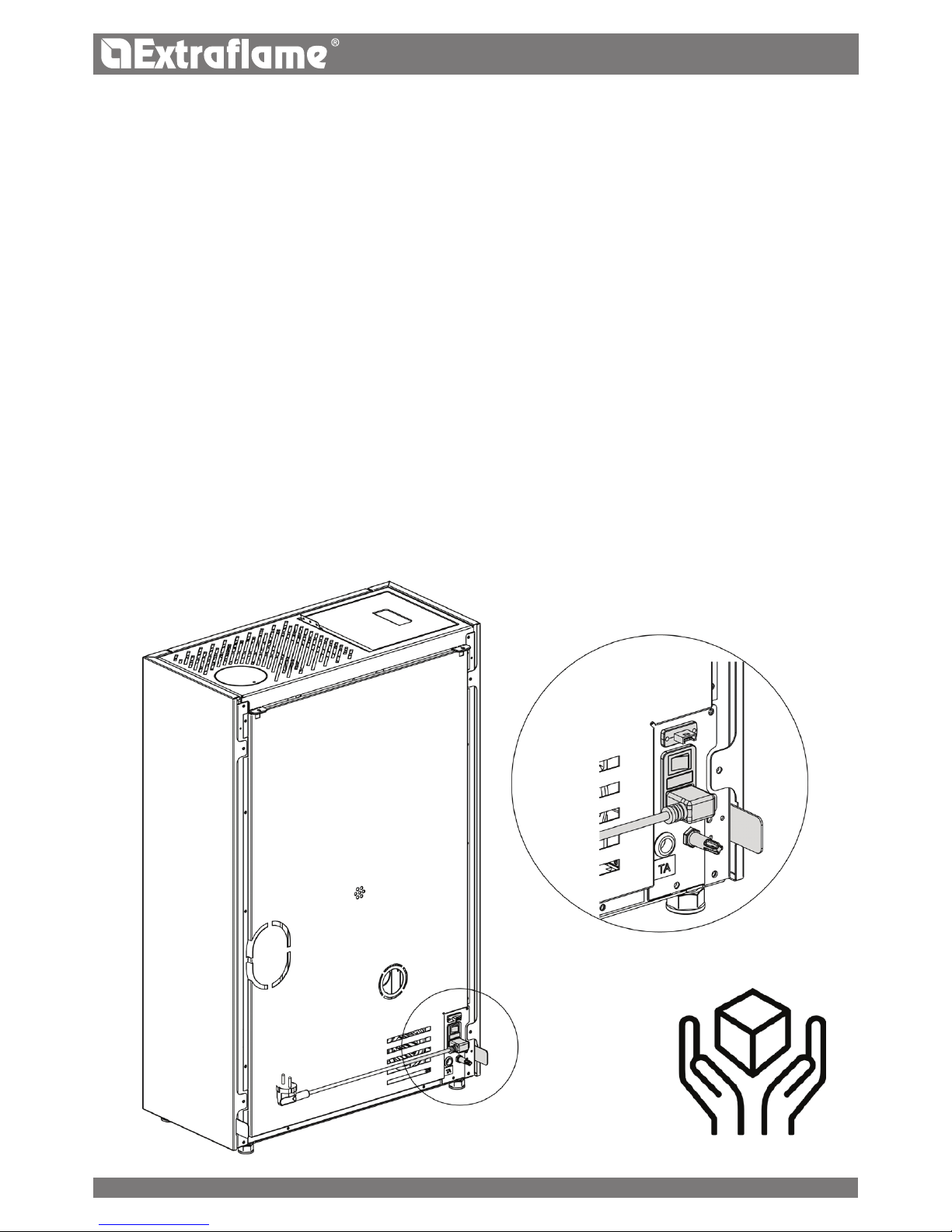
handle with care
ENGLISH
Page 5

5
ENGLISH
Warnings
This instructions manual is an integral part of the product: make sure that it always accompanies the
appliance, even if transferred to another owner or user, or if transferred to another place. If it is damaged
or lost, request another copy from the area technician. This product is intended for the use for which it has
been expressly designed. The manufacturer is exempt from any liability, contractual and extracontractual,
for injury/damage caused to persons/animals and objects, due to installation, adjustment and maintenance
errors and improper use.
Installation must be performed by qualied sta, which assumes complete responsibility for the
denitive installation and consequent good functioning of the product installed. One must also bear
in mind all laws and national, regional, provincial and town council Standards present in the country in
which the appliance has been installed, as well as the instructions contained in this manual.
The Manufacturer cannot be held responsible for the failure to comply with such precautions.
After removing the packaging, ensure that the content is intact and complete. Otherwise, contact the
dealer where the appliance was purchased.
All electric components that make up the product must be replaced with original spare parts exclusively
by an authorised after-sales centre, thus guaranteeing correct functioning.
safety
THE APPLIANCE MAY BE USED BY CHILDREN 8 YEARS OF AGE OR OLDER AND INDIVIDUALS
WITH REDUCED PHYSICAL, SENSORY, OR MENTAL CAPACITIES OR WITHOUT EXPERIENCE OR
THE NECESSARY KNOWLEDGE, PROVIDED THAT THEY ARE SUPERVISED OR HAVE RECEIVED
INSTRUCTIONS ON SAFE USE OF THE APPLIANCE AND THAT THEY UNDERSTAND THE INHERENT
DANGERS.
THE GENERATOR MUST NOT BE USED BY PERSONS (INCLUDING CHILDREN) WITH REDUCED
PHYSICAL, SENSORY AND MENTAL CAPACITIES OR WHO ARE UNSKILLED PERSONS, UNLESS THEY
ARE SUPERVISED AND TRAINED REGARDING USE OF THE APPLIANCE BY A PERSON RESPONSIBLE
FOR THEIR SAFETY.
THE CLEANING AND MAINTENANCE REQUIRED BY THE USER MUST NOT BE PERFORMED BY
CHILDREN WITHOUT SUPERVISION.
CHILDREN MUST BE CHECKED TO ENSURE THAT THEY DO NOT PLAY WITH THE APPLIANCE.
DO NOT TOUCH THE GENERATOR WHEN YOU ARE BAREFOOT OR WHEN PARTS OF THE BODY
ARE WET OR DAMP.
THE SAFETY AND ADjUSTMENT DEVICES MUST NOT BE MODIFIED WITHOUT THE AUTHORISATION
OR INDICATIONS OF THE MANUFACTURER.
DO NOT PULL, REMOVE, TWIST THE ELECTRICAL CABLES COMING OUT OF THE PRODUCT EVEN
IF IT IS DISCONNECTED FROM THE MAINS.
IT IS ADVISED TO POSITION THE POWER SUPPLY CABLE SO THAT IT DOES NOT COME INTO
CONTACT WITH HOT PARTS OF THE APPLIANCE.
THE POWER SUPPLY PLUG MUST BE ACCESSIBLE AFTER INSTALLATION.
DO NOT CLOSE OR REDUCE THE DIMENSIONS OF THE AIRING VENTS IN THE PLACE OF
INSTALLATION. THE AIRING VENTS ARE ESSENTIAL FOR CORRECT COMBUSTION.
We thank you for having chosen our company; our product is a great heating solution developed from the
most advanced technology with top quality machining and modern design, aimed at making you enjoy
the fantastic sensation that the heat of a ame gives, in complete safety.
Page 6

6
ENGLISH
DO NOT LEAVE THE PACKAGING ELEMENTS WITHIN REACH OF CHILDREN OR UNASSISTED
DISABLED PERSONS.
THE HEARTH DOOR MUST ALWAYS BE CLOSED DURING NORMAL FUNCTIONING OF THE
PRODUCT.
WHEN THE APPLIANCE IS FUNCTIONING AND HOT TO THE TOUCH, ESPECIALLY ALL EXTERNAL
SURFACES, ATTENTION MUST BE PAID
CHECK FOR THE PRESENCE OF ANY OBSTRUCTIONS BEFORE SWITCHING THE APPLIANCE ON
FOLLOWING A PROLONGED PERIOD OF INACTIVITY.
THE GENERATOR HAS BEEN DESIGNED TO FUNCTION IN ANY CLIMATIC CONDITION. IN
PARTICULARLY ADVERSE CONDITIONS (STRONG WIND, FREEzING) SAFETY SYSTEMS MAY
INTERVENE THAT SWITCH THE GENERATOR OFF. IF THIS OCCURS, CONTACT THE TECHNICAL AFTERSALES SERVICE AND ALWAYS DISABLE THE SAFETY SYSTEMS.
IN THE EVENT THE FLUE CATCHES FIRE, USE SUITABLE SYSTEMS FOR SUFFOCATING THE FLAMES
OR REQUEST HELP FROM THE FIRE BRIGADE.
THIS APPLIANCE MUST NOT BE USED TO BURN WASTE
DO NOT USE ANY FLAMMABLE LIQUIDS FOR IGNITION
DURING THE FILLING PHASE DO NOT PUT THE BAG OF PELLETS TO INTO CONTACT WITH THE
PRODUCT
THE MAjOLICAS ARE TOP QUALITY ARTISAN PRODUCTS AND AS SUCH CAN HAVE MICRO-DOTS,
CRACKLES AND CHROMATIC IMPERFECTIONS. THESE FEATURES HIGHLIGHT THEIR VALUABLE
NATURE. DUE TO THEIR DIFFERENT DILATION COEFFICIENT, THEY PRODUCE CRACKLING, WHICH
DEMONSTRATE THEIR EFFECTIVE AUTHENTICITY. TO CLEAN THE MAjOLICAS, IT IS RECOMMENDED
TO USE A SOFT, DRY CLOTH. IF A DETERGENT OR LIQUID IS USED, THE LATTER COULD PENETRATE
INSIDE THE CRACKLES, HIGHLIGHTING THEM.
routine Maintenance
Based on Decree 22 January 2008 n°37 art.2, routine maintenance means interventions aimed at reducing
degradation due to normal use, as well as dealing with accidental events entailing the need of rst
interventions, which however do not modify the structure of the system upon which one is intervening or
its intended use according to the requirements laid down by the technical standards in force and by the
manufacturer's use and maintenance manual.
Page 7
A
B
C
7
ENGLISH
Air inlet
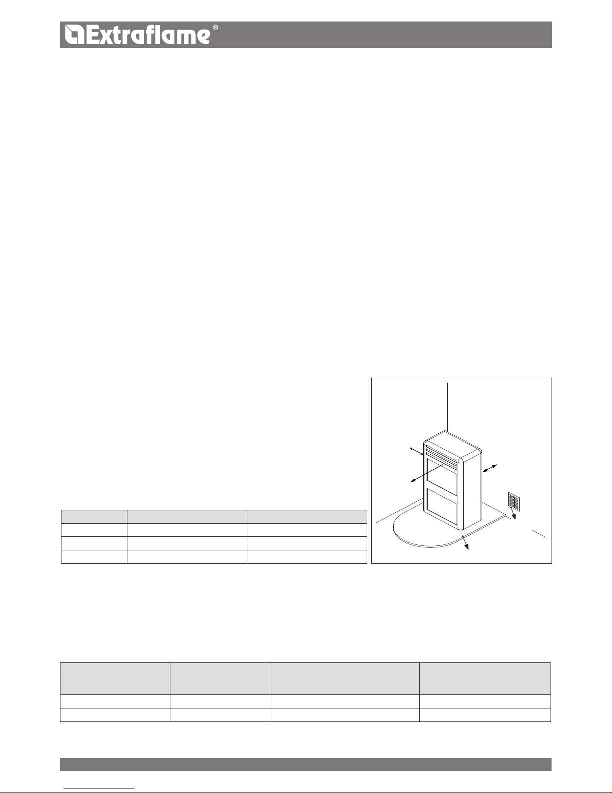
REFERENCES INFLAMMABLE OBJECTS NONINFLAMMABLE OBJECTS
A 200 mm 100 mm
B 1500 mm 750 mm
C 200 mm 100 mm
oor protection
InstallIng Inserts
When installing inserts, access must be prevented to the internal parts of the appliance and it must not be possible to access live parts during
extraction operations.
Any wiring, for example the power cable or room probe, must be positioned so as not to be damaged during movement of the insert and
must not come into contact with hot parts.
VentIlatIon and aeratIon of the InstallatIon premIses
Ventilation is deemed sucient when the room is equipped with air inlets according to the table:
Appliance categories Reference standard
Percentage of the
net opening section with respect to
the appliance fumes outlet section
Minimum net opening value of
the ventilation duct
Pellet stoves UNI EN 14785 - 80 cm²
Boilers UNI EN 303-5 50% 100 cm²
In any case ventilation is deemed sucient when the pressure dierence between the external and internal environment is equal to or less
than 4 Pa.
InstallatIon
general
The ue gas exhaust and hydraulic connections must be carried out by qualied personnel who must issue installation conformity
documentation compliant with national standards.
The installer must provide the owner or person acting for him, according to the legislation in force, with the declaration of conformity,
supplied with:
1) the use and maintenance manual of the appliance and of the system components (such as for example, the smoke ducts, chimney, etc.);
2) photocopy or photograph of the chimney plaque;
3) system booklet (where applicable).
The installer must ask to be issued with a receipt stating that the documentation has been provided, and must keep it with a copy of the technical
documentation relating to the installation.
For installation in a condominium, prior approval from the condominium's administrator must be requested.
Where required, check the exhaust gas emissions after installation. Should a sampling point be installed, it must be airtight.
CompatIBIlItY
Installation in premises with re hazards is forbidden. Installation in residential premises (except for sealed operation appliances) is also forbidden:
in which there are liquid fuel-operated appliances with continuous or intermittent operation, which draw the combustion air in the
room in which they are installed, or
in which there are type B gas appliances intended for room heating, with or without production of domestic hot water and in adjacent
and adjoining premises, or
in which, in any case, the depression measured during installation between the internal and external environment is greater than 4 Pa
InstallatIons In Bathrooms, Bedrooms and studIo flats
Installation in bathrooms, bedrooms and studio ats is only allowed for sealed or closed hearth appliances with ducted combustion air taken
from the outside.
posItIonIng and safetY dIstanCes
The support surfaces and/or points must have a suitable capacity to bear the overall weight
of the appliance, accessories and coverings.
If the oor is made of a combustible material,
we recommending using a non-combustible material to protect the front part from any
burnt material which might fall during routine cleaning operations.
The generator must be level to function properly.
The adjacent, side and rear walls and the supporting surface must be made of noncombustible material. Installation adjacent to combustible or heat sensitive materials is
allowed as long as there is a suitable safety distance in between, which for pellet stoves is:
Page 8
3 - 5%
Max 3 mt
8
ENGLISH
In the presence of type B gas appliances with intermittent operation not intended for heating, they must have their own aeration and/or
ventilation opening.
The air inlets must meet the following requirements:
they must be protected with grids, metal mesh, etc., but without reducing the net useful section;
they must be made so as to make the maintenance operations possible;
positioned so that they cannot be obstructed;
The clean and non-contaminated air ow can also be obtained from a room adjacent to that of installation (indirect aeration and
ventilation), as long as the ow takes place freely through permanent openings communicating with the outside.
The adjacent room cannot be used as a garage, or to store combustible material or for any other activity with a re hazard, bathroom,
bedroom or common room of the building.
flue gas eXhaust
The heat generator works in depression and is equipped with an outlet fan for ue gas extraction. There must be a single exhaust system for
the generator. Using a ue that is shared with other devices is not allowed.
The components of the ue gas exhaust system must be chosen in relation to the type of appliance to be installed in compliance with:
UNI/ TS 11278 in the event of metal chimneys, with particular attention to that stated in the specication;
UNI EN 13063-1 and UNI EN 13063-2, UNI EN 1457, UNI EN 1806 in the event of non-metallic chimneys.
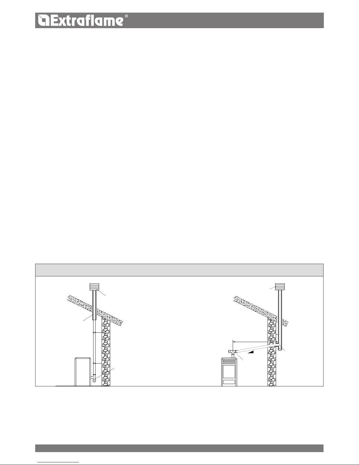
The length of the horizontal section must be minimal and, in any case, no longer than 3 metres, with a minimum upward slope of 3%
There must not be more than 4 direction changes including the one due to the use of the "T" element.
A “T” tting with a condensation collection cap must be provided at the base of the vertical section.
If the exhaust is not inserted in an existing ue, a vertical section with a windproof end piece is required (UNI 10683).
The vertical duct can be inside or outside the building. If the smoke duct is inserted in an existing ue, it must be certied for solid fuel.
If the smoke duct is outside the building, it must always be insulated.
The smoke ducts must have at least one airtight inlet for ue gas sampling.
All the sections of the ue gas duct must be accessible to inspection.
Inspection openings must be provided for cleaning.
If the generator has a fume temperature lower than 160°C+ ambient temperature caused by the high yield (contact technicians) it
MUST be resistant to humidity.
ChImneY Cap
The chimney caps must meet the following requirements:
they must have a useful outlet section no less than double that of the chimney/ducted system on which it is installed;
they must be adapted in order to prevent the penetration of rain and snow in the chimney/ducted system;
they must be built so that, in the event of winds coming from all directions and from any angle, the expulsion of combustion products
is in any case ensured;
Protection from rain
and wind
Condensation-proof
"T" tting with
inspection plug
Insulated ue
Insulated "T" tting
with inspection
plug
Protection from rain and wind
"T" tting
with
inspection
plug
eXamples of CorreCt ConneCtIon to the ChImneY
ConneCtIon to the maIns eleCtrIC supplY
The generator is supplied with an electric power cable to be plugged into a 230V 50 Hz socket, possibly with a circuit breaker switch. The
socket must be easily accessible.
The electrical system must be compliant with standards. The eciency of the earthing circuit must be checked. Unsuitable earthing of the
system can cause malfunctioning for which the manufacturer will not be held liable.
Power supply variations beyond 10% can cause faulty operation of the product.
Page 9
H
I
C
GFE
A
B
C C
J
K
D
D
9
ENGLISH
H
I
C
GFE
A
B
C C
J
K
D
D
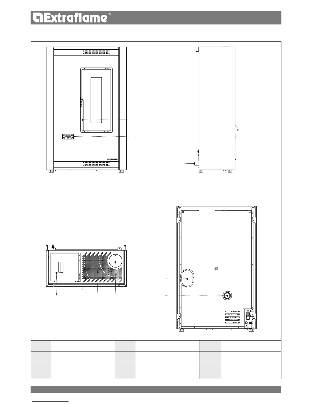
DETAILS OF LUISELLA
A Access to combustion chamber E Pellet hopper pressurised closure I
Combustive air
input
B Display F Room air outlet j Serial input
C Spacer G Upper fumes exhaust
K
On/O
Fuse
D Room sensor H Rear fumes exhaust
Power supply 230V
Page 10
10
ENGLISH
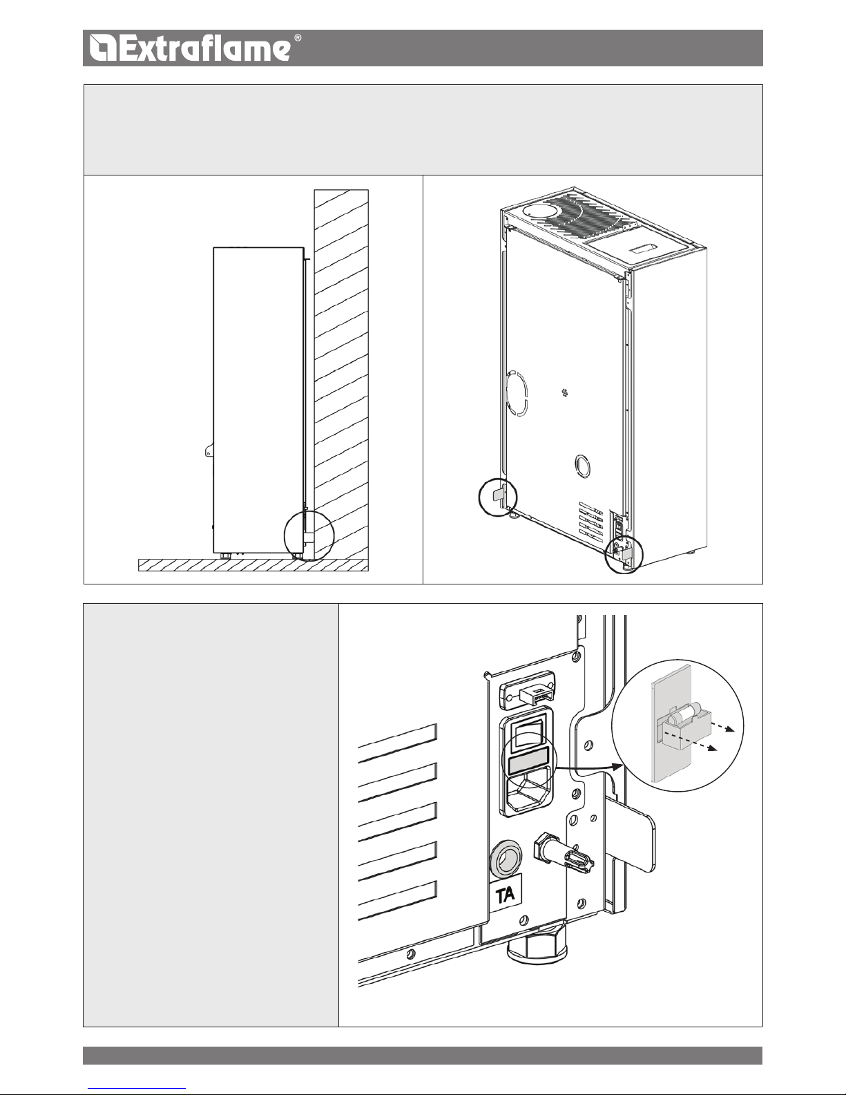
SPACERS
There are two spacers located on the rear of the machine which determine the minimum distance any support behind the stove.
The spacers must not be removed.
FUSE
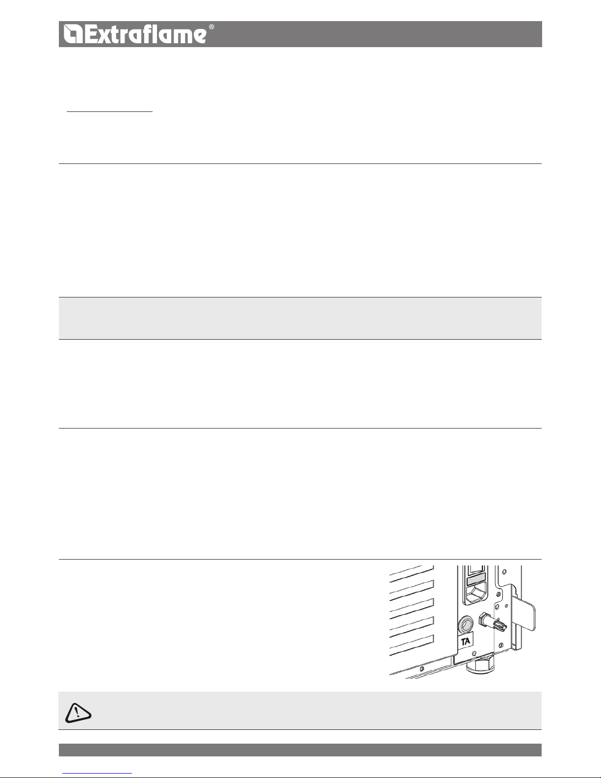
If there is no power supply to the stove, check the
state of the fuse located in the box between the
stove switch and the power cable connection.
Page 11
11
ENGLISH
STOVE POSITIONING
To ensure the stove works correctly, it should always be positioned so that it is perfectly level, using a spirit level.
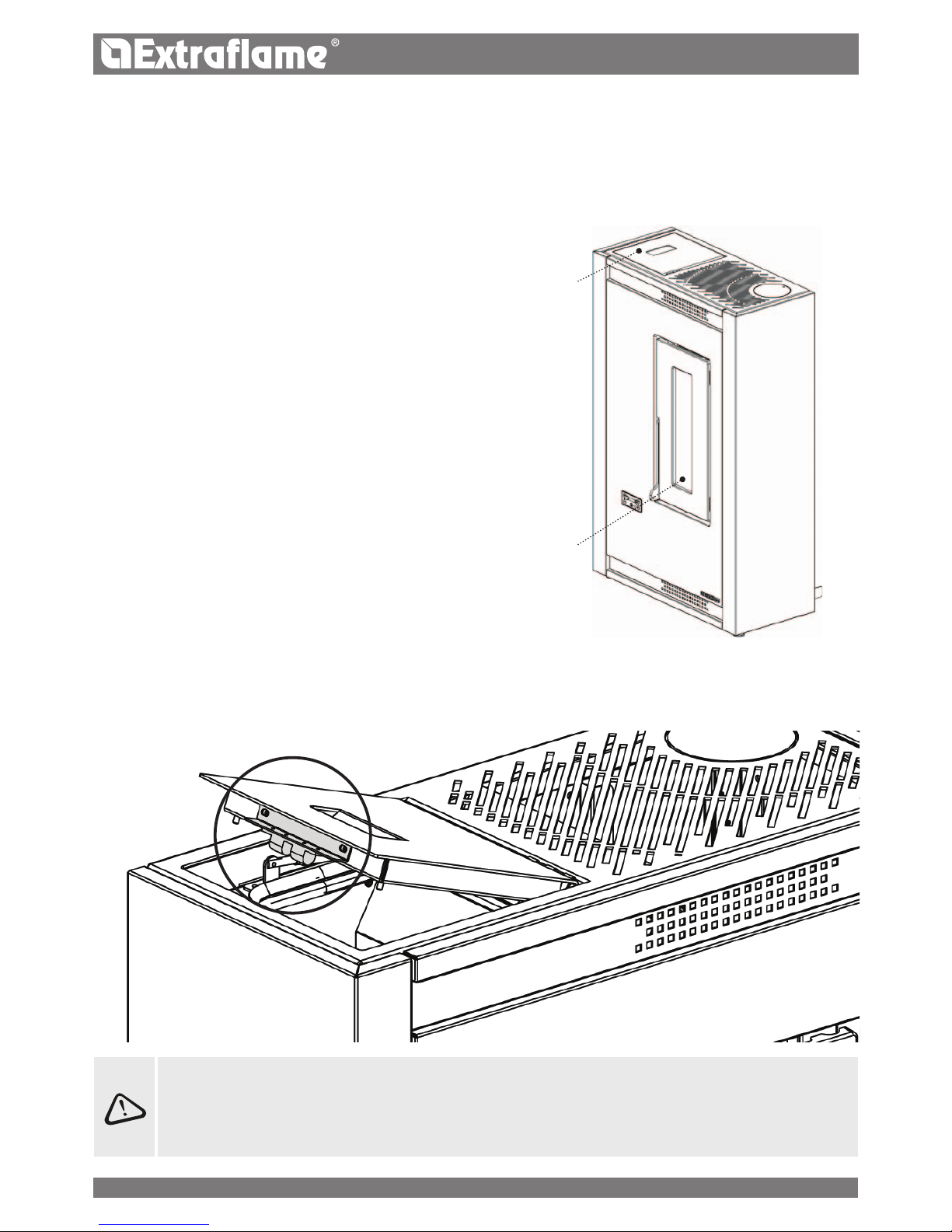
NOTE FOR CORRECT OPERATION
Pellet hopper lid
Fire door
The following indications must be respected for correct pellet
stove operation:
During stove operation, both the pellet hopper lid and the door
must always be closed.
Failure to comply with the above during operation will cause the
display to show the following:
"CLOSE HOPPER STOVE DOOR"
This indication means that you have 60" to close the hatch/door
and the pellet lid.
After 60 seconds, when the stove ignites, it will go to "DEPR
ALARM" mode, while during normal operation the stove will go
to "COOLING STAND BY" mode and then re-start automatically
when the correct conditions are present (stove cold, etc.).
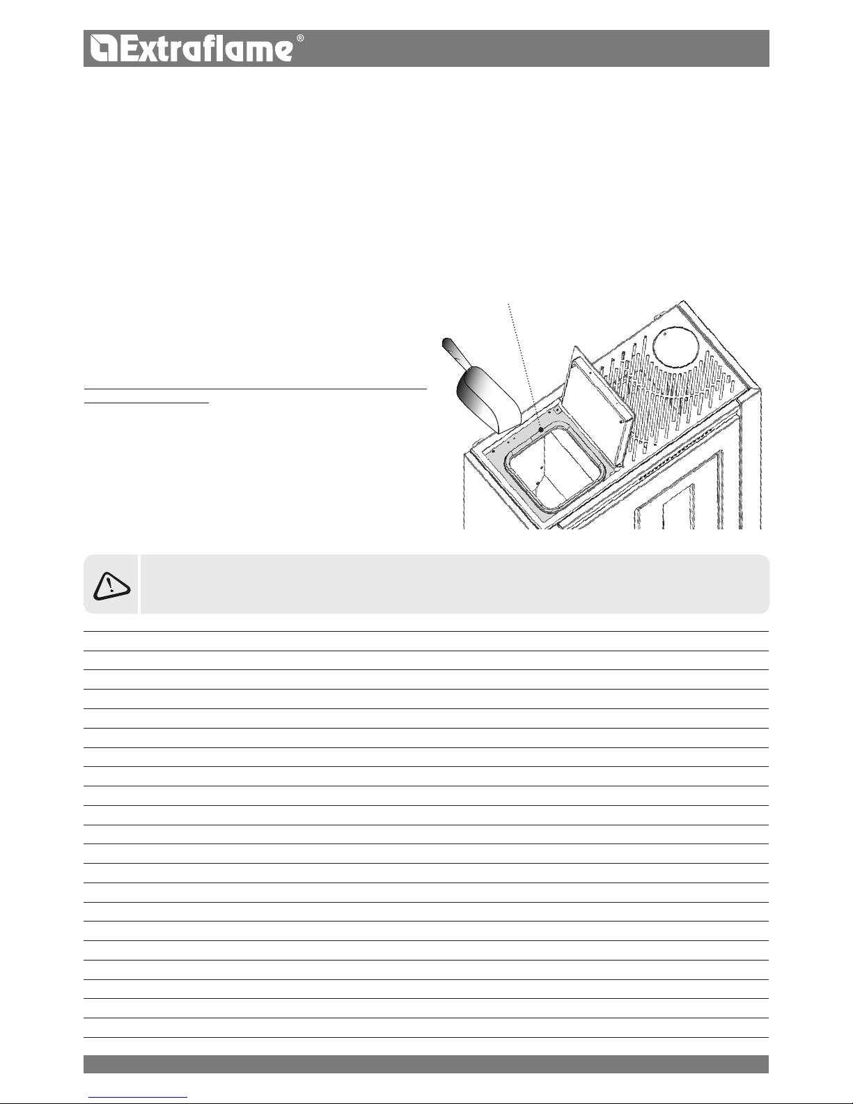
PELLET HOPPER PRESSURISED CLOSURE
During stove operation, the pellet hopper lid must always be closed.
Do not place the bag Directly on the stove when loaDing the hopper!
always use a scoop to loaD the hopper. Do not rub or place weights on the hopper seal.
Keep the hopper
liD seal support surface clean at all times. checK the conDitions of the seal frequently. if DamageD,
contact your local authoriseD technician.
Page 12
12
ENGLISH
PELLETS AND FEEDING
Pellets are made by applying high pressure to sawdust, or wood waste products (not containing paint) from sawmills, carpentry and other
activities related to processing and working with wood. Given that it does not use any glue to hold it together this type of fuel is completely
environmentally friendly. In fact the compactness of the pellets over time is guaranteed by a natural substance found in the wood itself: wood
coal. In addition to being an environmentally friendly fuel in that it pushes wood residues to the limits pellets also have technical advantages.
While wood has a caloric value of 4.4kWh/kg. (with 15% humidity after around 18 months of seasoning) the caloric value of pellets is 5 kWh/
kg. Pellet density is 650kg/m3 and the water content is equal to 8% of its weight. For this reason they do not require seasoning in order to
arrive at a suciently adequate degree of heat yield.
THE USE OF EXPIRED PELLETS OR ANY OTHER MATERIAL WILL AFFECT THE FUNCTIONALITY OF YOUR
GENERATOR AND MAY LEAD TO THE TERMINATION OF THE WARRANTY AND CESSATION OF ANY ACCOMPANYING
RESPONSIBILITY ON THE PART OF THE MANUFACTURER
The pellets used must comply with the characteristics described by the
following standards:
EN PLUS UNI EN 14961 2 UNI EN ISO 172252 class A1
A2
The manufacturer always recommended using pellets with a diameter
of 6 mm with its products.
PELLET STORAGE
In order to ensure problem-free combustion pellets must be stored in
a dry place.
Open the tank lid and load the pellets using a scoop.
Keep it clean
Page 13
13
ENGLISH
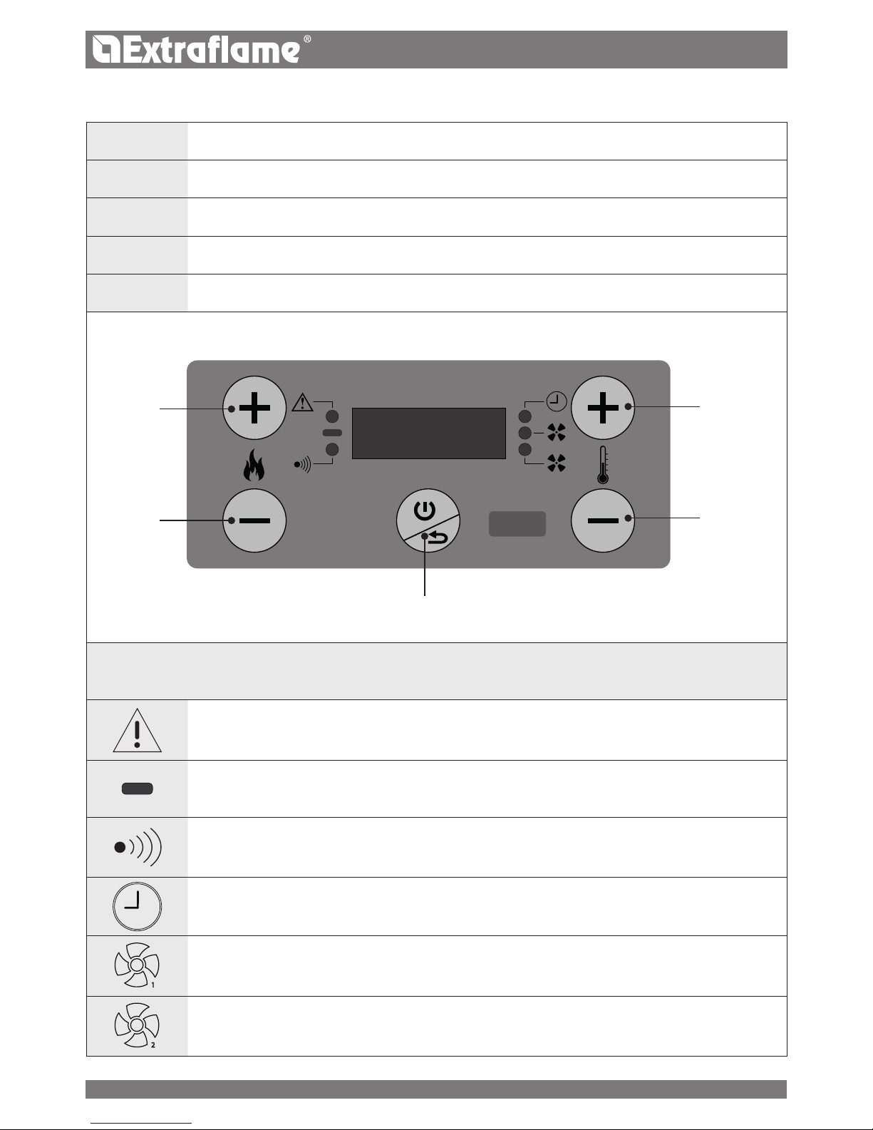
THE DISPLAY DESCRIPTION OF BASIC COMMANDS AND SYMBOLS
1
ON/OFF BUTTON
2
INCREASE SET POWER
3
DECREASE SET POWER
4
INCREASE SET THERMOSTAT
5
DECREASE SET THERMOSTAT
2
1
1
2
3
4
5
DISPLAY ICONS KEY
Indicates the presence of an alarm.
On: indicates the presence of an alarm.
O: indicates there are no alarms
Flashing: re door or pellet hopper open
Indicates the set temperature status
LED on: the stove is reaching the set temperature (room temperature still lower than set temperature)
LED o: the stove has reached the set temperature
Indicates communication by remote control
LED on: communication received by multi-purpose remote control
Indicates weekly programming operation
Light on = weekly programming active
Light o = weekly programming disabled
Flashing light = “delayed switch-o” function enabled
1
Indicates the tangential fan status
Light o = motor deactivated
Light on = motor activated
2
Not used
Page 14
14
ENGLISH
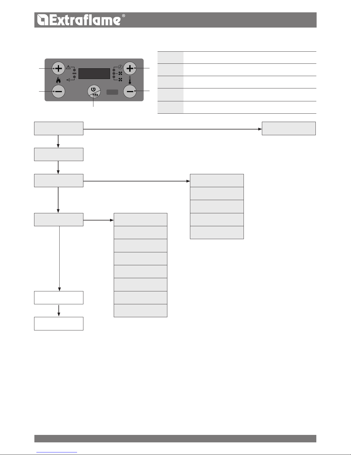
GENERAL MENU
BASIC INSTRUCTIONS
The following recommendations must be followed the rst times
the stove is ignited:
It is possible that slight odours are produced due to the drying
of the paints and silicone used. Do not remain in the room for long
periods.
Do not touch the surfaces as they could still be unstable.
Ventilate the room well several times.
The hardening of surfaces will stop after several heating cycles.
This appliance must not be used to burn waste.
Before lighting the stove, the following points must be checked:
The hopper must be loaded with pellets
The combustion chamber must be clean
The burn pot must be completely free and clean
Check the hermetic closure of the hoper, re door and ash
drawer
Check that the power cable is properly connected
The bipolar switch in the rear must be positioned on 1.
AIR
(Ventilation)
RPM
(Speed)
EASY
(Pellet calibration)
CRNO
(Chrono)
ABIL
(Enable)
PRG1
(PROGRAMMING 1)
PRG2
(PROGRAMMING 2)
SET
(Settings)
DATE
(Date)
PRG3
(PROGRAMMING 3)
DAY
(Day)
PRG4
(PROGRAMMING 4)
TIME
(Time)
LNG
(Language)
STBY
(Stand-by)
DELT
(Delta-T)
*STAT
(Status)
CF
(Celsius/Fahrenheit)
RES
(Reset)
*TECHNICIANS ONLY
*TECH
(Technical Menu)
1
ON/OFF BUTTON - EXIT MENU
2
SCROLL UP - CONFIRM
3
SCROLL DOWN
4
PRESS AND HOLD TO ACCESS MENU - ACCESS SELECTED MENU INCREASE VALUE
5
DECREASE VALUE
2
1
1
2
3
4
5
Page 15
15
ENGLISH
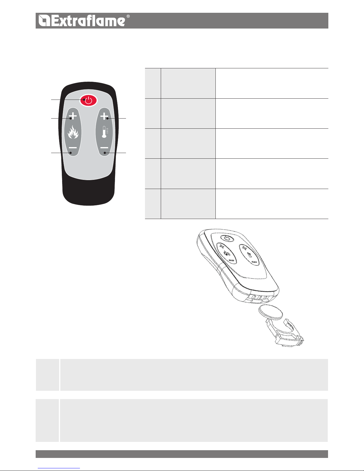
BATTERY TYPE AND REPLACEMENT
The battery is housed in the lower part of the remote control.
To replace it, remove the battery holder (as indicated
in the diagram on the back of the remote control), remove or insert
the battery following the symbols printed on the remote control
and the battery.
One 3V CR2025 lithium coin battery is required to operate the
remote control.
REMOTE CONTROL
When using the remote control, you can regulate the heating power, room temperature required and switch the device on/o.
2
3
1
4
5
1
ON/OFF Prolonged pressure turns the stove on or o.
2
POWER INCREASE Increases operating power
3
POWER DECREASE Decreases operating power
4
T° INCREASE Increases the set thermostat
5
T° DECREASE Decreases the set thermostat.
J
IF THE REMOTE CONTROL IS SWITCHED OFF BECAUSE THERE IS NO BATTERY, THE STOVE CAN BE CONTROLLED FROM
THE COMMAND PANEL LOCATED ON THE LOWER PART OF THE STOVE. WHEN CHANGING THE BATTERY, MAKE SURE
YOU FOLLOW THE SYMBOLS PRINTED ON THE INNER SLOT OF THE REMOTE CONTROL.
J
NO IGNITION
THE APPLIANCE MAY FAIL TO LIGHT BECAUSE THE AUGER IS EMPTY AND NOT ALWAYS ABLE TO LOAD THE BURN POT
WITH THE NECESSARY QUANTITY OF PELLETS IN TIME TO REGULARLY IGNITE THE FLAME.
IF THE PROBLEM OCCURS AFTER ONLY A FEW MONTHS OF OPERATION, CHECK THAT THE ROUTINE CLEANING
DESCRIBED IN THE STOVE BOOKLET HAS BEEN CARRIED OUT CORRECTLY.
Page 16
16
ENGLISH
COMMISSIONING SETTINGS
Once the power cable at the back of the generator has been connected, move the switch, also located on the back, to (I).
The switch at the back of the generator powers the generator board.
The generator remains o and an initial screen appears on the panel, displaying OFF.
MAINS POWER FREQUENCY 50/ 60HZ
If the generator is installed in a country with a frequency of 60Hz, the generator will display “POWER FREQUENCY ERROR ". In this case, adjust
the frequency to 60Hz.
Press and hold key 4 to access the power frequency error menu. Use keys 4 and 5 to select the correct frequency and 2 to conrm and exit.
DATE DATE
This menu allows the date to be set.
CONTROLS PROCEDURE
Press and hold key 4.
Press key 3 until SET appears and access with key 4.
Press key 3 until DATE appears and access with key 4.
Use keys 2 and 3 to select the sub-item DAY, MNTH or YEAR to set each one.
Access with key 4.
Modify with keys 4 and 5 and conrm with key 2
Press key 1 several times to exit the menu.
DAY DATE
This menu allows the date to be changed. (DAY1 = Monday - DAY7 = Sunday)
CONTROLS PROCEDURE
Press and hold key 4.
Press key 3 until SET appears and access with key 4.
Press key 3 until DAY appears and access with key 4.
Set the day using keys 4 and 5 and conrm with key 2.
Press key 1 several times to exit the menu.
TIME TIME
This menu allows the time to be set.
CONTROLS PROCEDURE
Press and hold key 4.
Press key 3 until SET appears and access with key 4.
Press key 3 until TIME appears and access with key 4.
Use keys 2 and 3 to select and set HOUR or MIN.
Key 4 to access, 4 and 5 to modify and 2 to save
Press key 1 several times to exit the menu.
LNG LANGUAGE
This menu allows the preferred language to be selected. The languages available are: Italian - English - German - French - Spanish - Portuguese
CONTROLS PROCEDURE
Press and hold key 4.
Press key 3 until SET appears and access with key 4.
Press key 3 until LNG appears and access with key 4.
Set the language using keys 4 and 5 and conrm with key 2.
Press key 1 several times to exit the menu.
CF CELSIUS/FAHRENHEIT
This menu allows to you set the desired unit of measurement. "C" for Celsius (°C) - "F" for Fahrenheit (°F)
CONTROLS PROCEDURE
Press and hold key 4.
Press key 3 until SET appears and access with key 4.
Press key 3 until CF appears and access with key 4.
Set the unit of measurement using keys 4 and 5 and conrm with key 2.
Press key 1 several times to exit the menu.
Page 17

17
ENGLISH
IGNITION
Once the points listed previously have been checked, press key 1 for three seconds to ignite the stove. There are 15 minutes available to
detect the presence of the ame during the ignition phase. When the control temperature is reached, stove interrupts the ignition phase and
switches to PREPARATION.
PREPARATION
During the preparation phase, the stove stabilises combustion, increasing it progressively, to then start ventilation and switch to WORK
WORK
In the work phase, the stove switches to the Set Power dened by the user, heating the room until Set Thermostat is achieved. See next
heading.
SET THERMOSTAT
The Set room thermostat can be set with keys 4 and 5, from LOU - 7°C - 40°C - HOT. If the value is between 07°C-40°C, the stove controls the
room temperature by means of an on-board probe. Once the set temperature has been reached, the stove automatically decreases the power,
ensuring the best comfort and reducing pellet consumption. This process is called “modulation”.
LOU HOT
If the Set Thermostat is "LOU" (set under the 7° threshold), temperature control passes to the additional thermostat contact, thus bypassing
the on-board temperature probe.
If the contact is closed (fullled), the stove decreases to minimum value.
If the contact is open (request), the stove works at the set power.
If the setting is on “HOT” (set above 40°C), the stove only works at the set power, thus bypassing the external contact and the temperature
probe.
SET POWER
Set Power has 5 operating levels. The power can be changed with keys 2 or 3.
Power 1 = minimum level - Power 5 = maximum level.
Press key 1 to exit and save the change.
AUTO BLOW
During the work phase, the stove cleans the burn pot at regular intervals with an "AUTO BLOW".
When this procedure starts, a message is displayed. During the "AUTO BLOW" procedure, the pellet feed slow down and the fumes motor
increases.
After cleaning, the stove resumes working at normal operational conditions.
SWITCHOFF
Press key 1 for three seconds.
Once this operation has been performed, the appliance automatically enters the switch-o phase, blocking the supply of pellets.
The ue gas exhaust motor and the hot air ow motor will remain on until the stove temperature has dropped below the safety settings.
REIGNITION
The stove can only be re-ignited if the temperature of the exhaust fumes is lower than the pre-set threshold and the minimum safety time has
passed.
OPERATION AND LOGIC
DO NOT USE ANY TYPE OF FLAMMABLE LIQUIDS FOR IGNITION!
DO NOT ALLOW THE BAG OF PELLETS TO COME INTO CONTACT WITH THE BOILING HOT STOVE DURING THE
FILLING PHASE!
IN THE EVENT OF CONTINUED FAILURE TO LIGHT, CONTACT AN AUTHORISED TECHNICIAN.
Page 18
18
ENGLISH
AIR VENTILATION
The menu allows you to adjust the speed (-2, -1, 0, +1, +2) of the front fan.
CONTROLS PROCEDURE
Press and hold key 4.
Access AIR. with key 4.
Access RPM with key 4.
Adjust speed with keys 4-5 and 2 to conrm.
Press key 1 several times to exit the menu.
EASY PELLET CALIBRATION
The volumetric weight of the pellet is the ratio between the weight and the volume of the pellet. This ratio may change while keeping the
quality of the pellet unchanged. By using the EASY function, it is possible to change the calibration of the volumetric weight by increasing
or decreasing the pre-set values.
In the stove program, the available values go from “– 3” to “+ 3”; all stoves are calibrated during production with the optimal value which is 0
If you notice an excessive deposit on the burning pot, access the EASY program and lower the value of one unit to “- 1”; then wait until the
next day and if there is no improvement, decrease again, to a maximum of “- 3”. Instead, if it is necessary to increase the calibration of the
volumetric weight of the pellet, go from the factory value “0” to “+ 1, + 2, + 3” as required.
CONTROLS PROCEDURE
Press and hold key 4.
Press key 3 until EASY appears and access with key 4.
Adjust using keys 4 and 5 and conrm with key 2.
Press key 1 several times to exit the menu.
EXCESSIVE PELLET DEPOSIT IN THE BURNING POT NORMAL OPERATION MINIMUM PELLET DEPOSIT IN THE BURNING POT
-3 -2 -1 0 +1 +2 +3
THIRD DECREASE
RANGE IF THE
FIRST TWO ARE
NOT ENOUGH
SECOND
DECREASE
RANGE IF THE
FIRST IS NOT
ENOUGH
FIRST DECREASE
RANGE (TEST FOR
1 D AY)
OPTIMAL FACTORY
VALUE
FIRST INCREASE
RANGE
SECOND
INCREASE RANGE
IF THE FIRST IS
NOT ENOUGH
THIRD INCREASE
RANGE IF THE
FIRST TWO ARE
NOT ENOUGH
N.B.: If this calibration does not solve the pellet deposit in the burn pot, please contact your local after-sales centre.
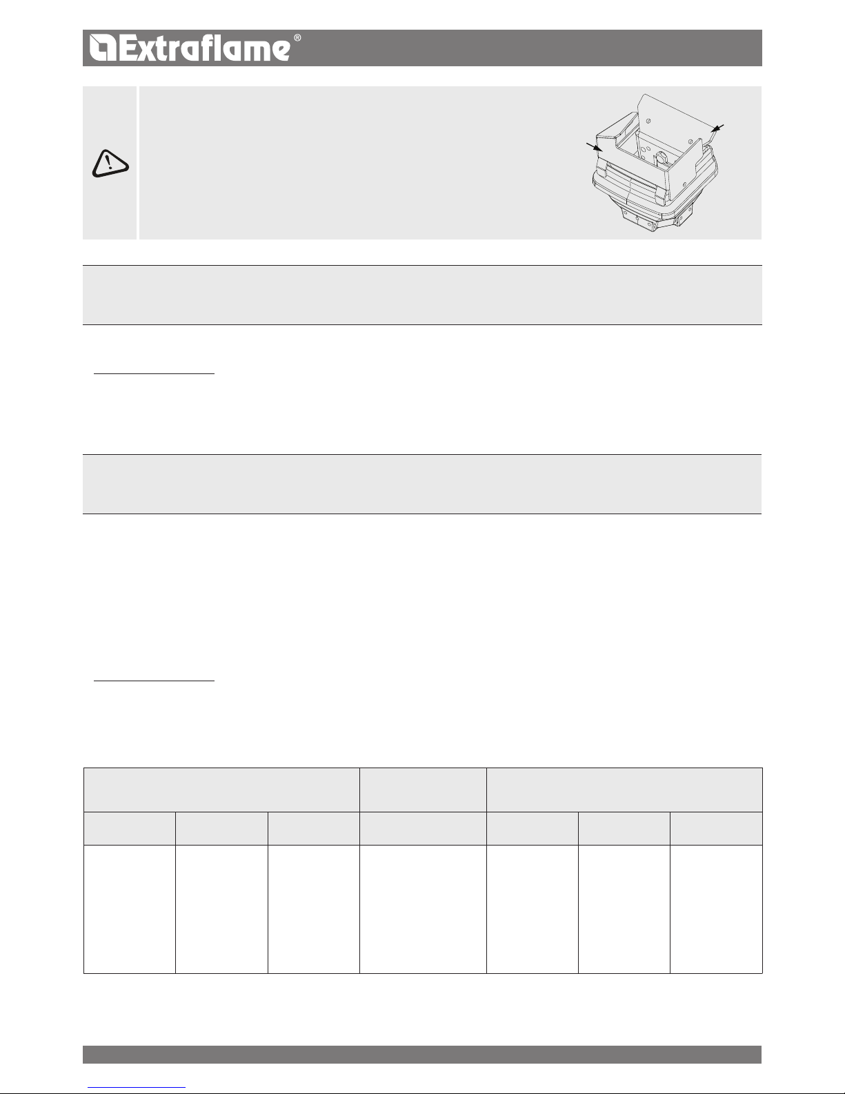
IT IS FORBIDDEN TO USE THE DEVICE WITHOUT A PARTITION A AND FLAME
GUARD B.
REMOVAL WILL COMPROMISE THE SAFETY OF THE PRODUCT AND RESULT
IN THE IMMEDIATE NULLIFICATION OF THE WARRANTY PERIOD.
IN THE EVENT OF WEAR OR DETERIORATION, REQUEST THE PART'S
REPLACEMENT FROM THE AFTERSALES SERVICE.
REPLACEMENT DOES NOT FALL WITHIN THE PRODUCT WARRANTY AS THE
PART IS SUBJECT TO WEAR.
A
B
Page 19

19
ENGLISH
CRNO CHRONO
This function allows the stove's ignition and switch-o to be automatically programmed.
The factory setting for CHRONO is o.
The chrono allows the programming of 4 time slots within a day, which can be used every day of the week.
Ignition and switch-o times can be set for each time slot, along with the specic days of application for the programmed time slot,
the desired temperature and power setting.
Current day and time settings are essential for the correct operation of the Chrono.
Recommendations
Before using the chrono function, you must set the current day and time, so check that you have followed the points listed in the sub-chapter
“DATE, DAY and TIME”. To use the chrono function correctly, you must activate it as well as program it. The four time slots can be overlapped
using the time switch on and o settings, This allows you to obtain a combination of times in which you can set dierent temperatures and
power without inuencing the stove work status.
NB: if overlapping time slots are set, the stove will stay on until the latest switch-o time.
PRG 14 PROGRAMMING 14
Prg x allows you to set the ignition time (STRT) and switch-o time (STOP), the days (DAY1= Monday / DAY7 = Sunday) included in the
programmed slot and the temperature (TEMP) (lou - 7° - 40° - hot), as well as the power (POW.) required. Current day and time settings are
essential for the correct operation of the Chrono.
CONTROLS PROCEDURE
Press and hold key 4.
Press key 3 until CRNO appears and access with key 4.
Select the slot using keys 2-3 and access it with 4.
Select one of the following options: STRT, STOP, DAY, TEMP and POW. and access with 4
Adjust using keys 4 and 5 and conrm with key 2.
Press key 1 several times to exit the menu.
ABIL ENABLE
Allows the chrono and the dierent stove time slots to be enabled/disabled.
CONTROLS PROCEDURE
Press and hold key 4.
Press key 3 until CRNO appears and access with key 4.
Press 4 to access ENABLE, 4-5 to select ON and OFF, and 2 to conrm.
Press key 1 several times to exit the menu.
STAT STATUS
References reserved for the technician
Page 20
20
ENGLISH
J
WHEN THE WEEKLY PROGRAMMER IS SHOWN ON THE DISPLAY, THE INDICATOR LIGHT WILL BE ON.
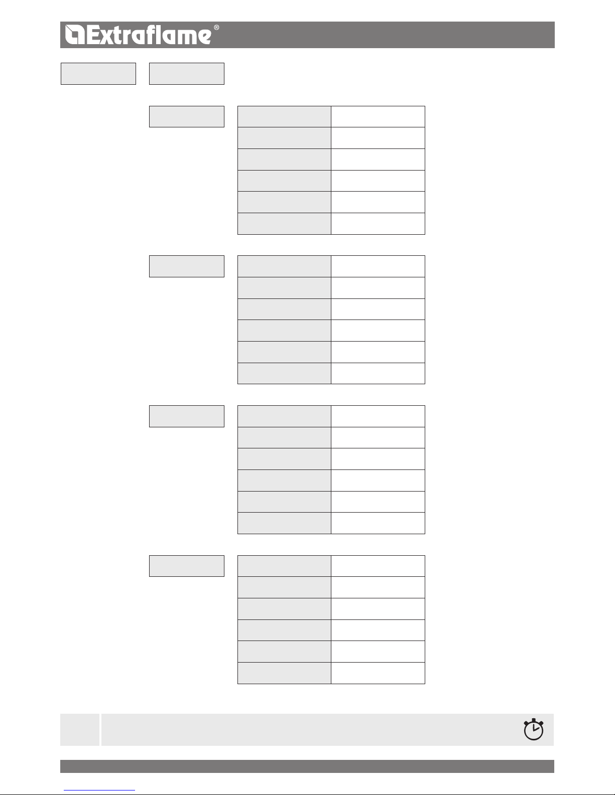
CRNO > ABIL
Enables/disables all the set chrono
>
PRG1 > ABIL
On/O Enabling/disabling PRG 1
>
STRT
OFF-00:00-23:50 PRG1 start time
>
STOP
OFF-00:00-23:50 PRG1 stop time
>
DAY1...DAY7
On/o Enabling/disabling days for PRG1
>
TEMP
LOU - 07- 40 °C - HOT Set thermostat PRG1
>
POW.
1-5 Set power PRG1
>
PRG2 > ABIL
On/O Enabling/disabling PRG 2
>
STRT
OFF-00:00-23:50 PRG2 start time
>
STOP
OFF-00:00-23:50 PRG2 stop time
>
DAY1...DAY7
On/o Enabling/disabling days for PRG2
>
TEMP
LOU - 07- 40 °C - HOT Set thermostat PRG2
>
POW.
1-5 Set power PRG2
>
PRG3 > ABIL
On/O Enables/disables PRG3
>
STRT
OFF-00:00-23:50 PRG3 start time
>
STOP
OFF-00:00-23:50 PRG3 stop time
>
DAY1...DAY7
On/o Enabling/disabling days for PRG3
>
TEMP
LOU - 07- 40 °C - HOT Set thermostat PRG3
>
POW.
1-5 Set power PRG3
>
PRG4 > ABIL
On/O Enabling/disabling PRG 4
STRT
OFF-00:00-23:50 PRG4 start time
STOP
OFF-00:00-23:50 PRG4 stop time
DAY1...DAY7
On/o Enabling/disabling days for PRG4
TEMP
LOU - 07- 40 °C - HOT Set thermostat PRG4
POW.
1-5 Set power PRG4
Page 21
02:00 23:0008:00 16:30
t
02:00 23:0008:00 16:30
t
3
1
02:00 23:0008:00 16:30
t
22°
18°
2
1
21
ENGLISH
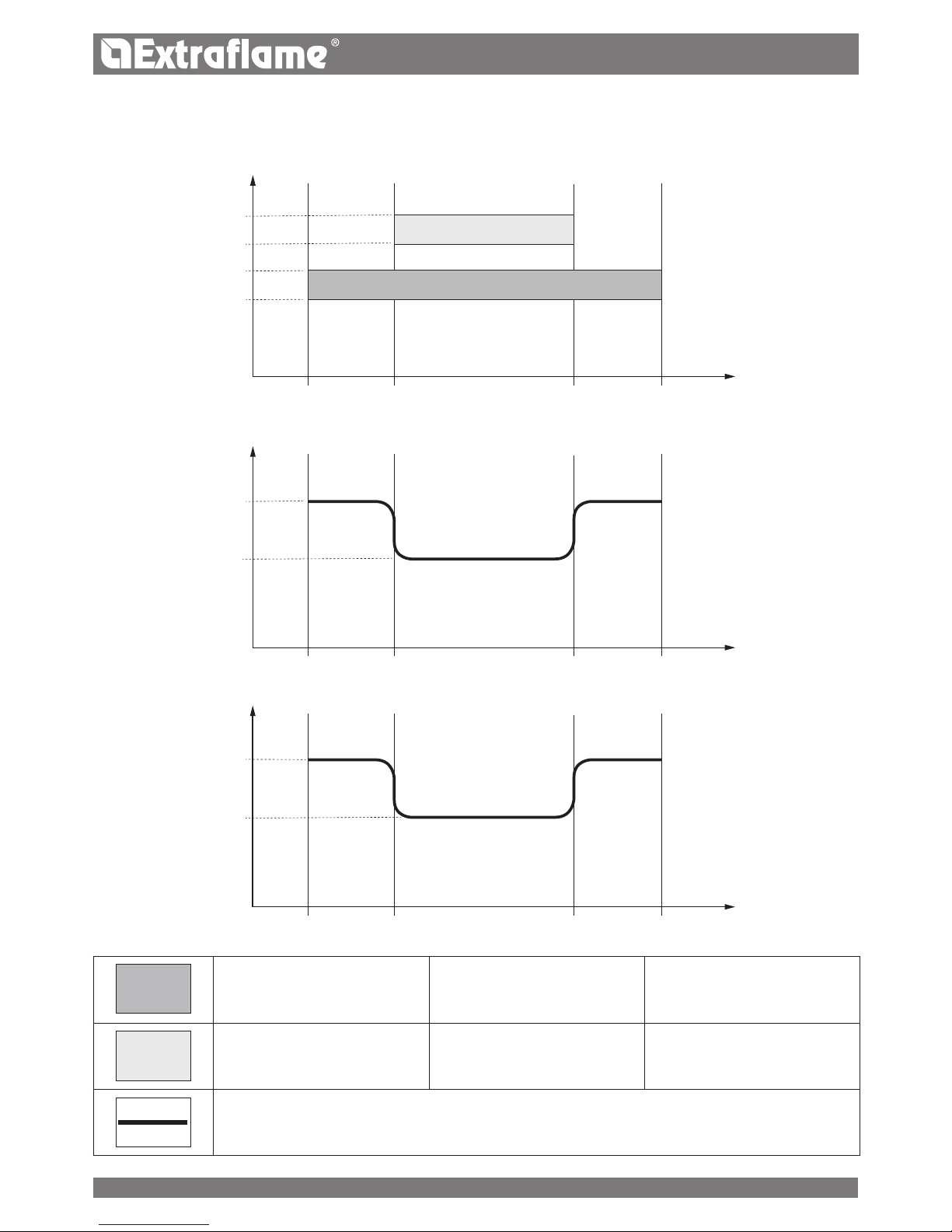
Time slot 1
start 02:00
stop 23:00
power 3 - set temp 22°C
Time slot 2
start 08:00
stop 16:30
power 1 - set temp 18°C
stove operation
Time slot
Power
Set temperature
EXAMPLE OF CHRONO OVERLAPPING TIME/SLOTS
Page 22
22
ENGLISH
STBY STAND-BY)
The stand-by function is used if the stove needs to be turned o immediately instead of a power modulation.
CONTROLS PROCEDURE
Press and hold key 4.
Press key 3 until SET appears and access with key 4.
Press key 3 until STBY appears and access with key 4.
Enable/disable using keys 4 and 5 and conrm with key 2.
Press key 1 several times to exit the menu.
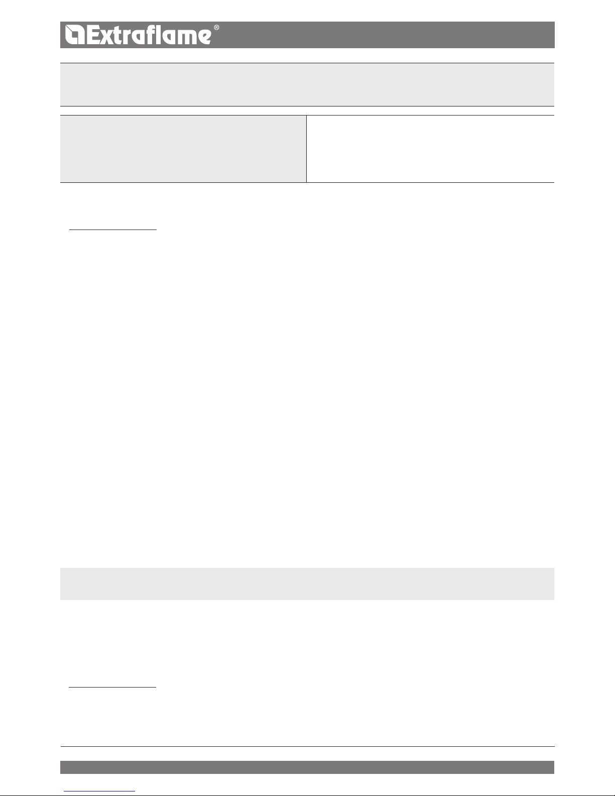
DATE
DAY
TIME
LNG
CF
SEE CHAPTER: COMMISSIONING SETTINGS.
J
FOR CORRECT OPERATION, SET THERMOSTAT SHOULD BE SET IN LOU.
> SEE THE INSTALLATION CHAPTER SUPPLEMENTARY THERMOSTAT
SET SETTINGS
STBY FUNCTION SET TO ON
When the Stand-by function is active (ON), if the room temperature exceeds the SET THERMOSTAT value + DELT, the stove will switch o
after a pre-set (default) delay period, displaying STBY.
When the room temperature is lower than the SET THERMOSTAT - DELT, the stove cools down, if necessary, and then switches o.
STBY FUNCTION SET TO OFF FACTORY DEFAULT SETTING
In the event the Stand-by function is not activated (OFF), if the stove exceeds the set room temperature, it will switch to the minimum power
level, modulating and displaying MODULATION. When the room temperature is lower than the SET THERMOSTAT the stove will restart at
the set power and WORK will be displayed on the screen.
OPERATION WITH SUPPLEMENTARY THERMOSTAT OPTIONAL
STBY FUNCTION SET TO OFF FACTORY DEFAULT SETTING
In the even the Stand-by function is not activated (OFF), if the stove reaches the room temperature set on the supplementary thermostat
(closed contact), it will switch to the minimum power level and display MODULATION. When the room temperature is lower than the set value
on the supplementary thermostat (open contact), the stove will restart at the set power, and WORK will be displayed on the screen.
STBY FUNCTION SET TO ON
If the STAND-BY function is activated (ON), when the room temperature set on the supplementary thermostat is reached (closed contact), the
stove will switch o after a pre-set (default) delay period, and STBY will be displayed on the screen.
When the room temperature is lower than the supplementary thermostat (open contact), the stove cools down, if necessary, and then reignites.
DELT DELTAT
This function allows you to set the delta-t for igniting and switching o the stove, used as a room temperature adjustment interval if there
is no external thermostat. The exact temperature for ignition is SET THERMOSTAT - Delta-T. The temperature for switching o is SET
THERMOSTAT + Delta-T.
The possible values for Delta-T range from: 0.5 - 5°C
CONTROLS PROCEDURE
Press and hold key 4.
Press key 3 until SET appears and access with key 4.
Press key 3 until DELT appears and access with key 4.
Adjust with keys 4-5 and 2 to conrm.
Press key one several times to conrm and exit the menu.
Page 23
23
ENGLISH
RES RESET
Allows the user to reset all modiable values to the default values.
CONTROLS PROCEDURE
Press and hold key 4.
Press key 3 until SET appears and access with key 4.
Press key 3 until RES appears and access with key 4.
Use keys 4 and 5 to select ON or OFF and conrm with 2.
IF A SUPPLEMENTARY THERMOSTAT HAS BEEN INSTALLED, THE CONNECTION MUST BE MADE BY THE QUALIFIED
TECHNICIAN DIRECTLY IN THE BOARD. CONTACT THE DEALER FOR FURTHER DETAILS.
ADDITIONAL FUNCTIONS
FIRST LOAD
This function allows you to activate the gearmotor for loading pellets continuously.
Before starting the function, make sure the stove is cold and “OFF”.
Press keys 2 + 5 at the same time for two seconds until the message "FIRST LOAD".
To stop continuous loading, just press and hold key 1 for 3 seconds.
DELAY SWITCHOFF
You can program a delayed switch-o for the stove. For example, if it is 8 pm and the delayed switch-o is set to 1h, the stove will automatically
switch o at 9 pm.
If you press and hold keys 2+4 at the same time, the screen “DELAY SWITCHOFF” will appear, alternating with the countdown (this setting
can only be congured if the stove is in the preparation phase or working).
Use keys 4 and 5 to increase/decrease the number of hours after which the stove will automatically start the nal cleaning phase.
The number of hours range from OFF, 1 to 9.
Press key 1 to conrm and return to the home page.
The remaining operating time is indicated by displaying at one-minute intervals "SWITCH OFF IN HOURS” and the time "xx:xx".
SUPPLEMENTARY THERMOSTAT INSTALLATION OPTIONAL
The stove can control the room temperature through a supplementary thermostat (optional).
After the stove is turned on (by pressing key 1 or through the chrono mode), it will work to
reach the temperature set on the thermostat, displaying WORK (open contact). The standard
room sensor is by-passed automatically.
When the thermostat temperature has been reached (closed contact), the stove switches to
minimum power level and displays MODULATION ON THE SCREEN.
Page 24
24
ENGLISH
CLEANING AND MAINTENANCE
ALWAYS FOLLOW THE INSTRUCTIONS IN COMPLETE SAFETY!
Make sure that the power supply cable plug is disconnected, since the generator could be programmed to switch-on.
That the generator is completely cold.
The ashes are cold.
Ensure proper ventilation of the room when cleaning the stove.
Lack of cleaning jeopardises correct operation and safety!
MAINTENANCE
For correct operation, the generator must undergo routine maintenance by a qualied technician, at least once a year.
The periodic inspection and maintenance operations must always be performed by specialised, qualied technicians, who operate in
accordance with the laws in force and the instructions given in this use and maintenance manual.
PERIODIC CLEANING BY THE USER
As indicated in this use and maintenance manual, periodic cleaning must be performed paying great attention, after having read the
indications, to the procedures and times described herein.
CLEANING THE SURFACES AND COVERING
Never use abrasive or chemically aggressive detergents for cleaning!
The surfaces must be cleaned when the generator and covering are completely cold. Fir maintenance of surfaces and metal parts, just use a
cloth dampened in water or water and neutral soap.
Failure to comply with the indications can damage the surfaces of the generator and cause the warranty to become null and void.
CLEANING THE CERAMIC GLASS
Never use abrasive or chemically aggressive detergents for cleaning!
The ceramic glass must only be cleaned when the glass is completely cold.
To clean the ceramic glass, simply use a dry brush and some damp newspaper dipped in ash. If the glass is very dirty, use a specic cleaning
agent for ceramic glass. Spray a small amount on a cloth and use it on the ceramic glass. Do not spray the cleaning agent or any other liquid
directly on the glass or seals!
Failure to comply with these instructions may damage the surfaces of the ceramic glass and cause the invalidation of the warranty.
CLEANING THE PELLET TANK
When the tank is completely empty, disconnect the power cable of the generator and remove the residues rst (dust, chippings, etc.) from the
empty tank, and then ll it.
EVERY YEAR, GET THE FUME DISCHARGE SYSTEM, THE FLUE PIPES AND THE "T" FITTINGS AND INSPECTION CAPS
CLEANED IF PRESENT, ALSO THE ELBOWS AND HORIZONTAL SECTIONS!
THE CLEANING FREQUENCY OF THE GENERATOR IS INDICATIVE! IT DEPENDS ON THE QUALITY OF THE PELLETS USED
AND FREQUENCY OF USE.
THESE OPERATIONS MUST BE PERFORMED MORE FREQUENTLY.
TO FIND OUT WHERE YOUR NEAREST SERVICE CENTRE IS, CONTACT YOUR DEALER OR GO TO THE WEBSITE:
WWW.LANORDICA-EXTRAFLAME.COM
Page 25
25
ENGLISH
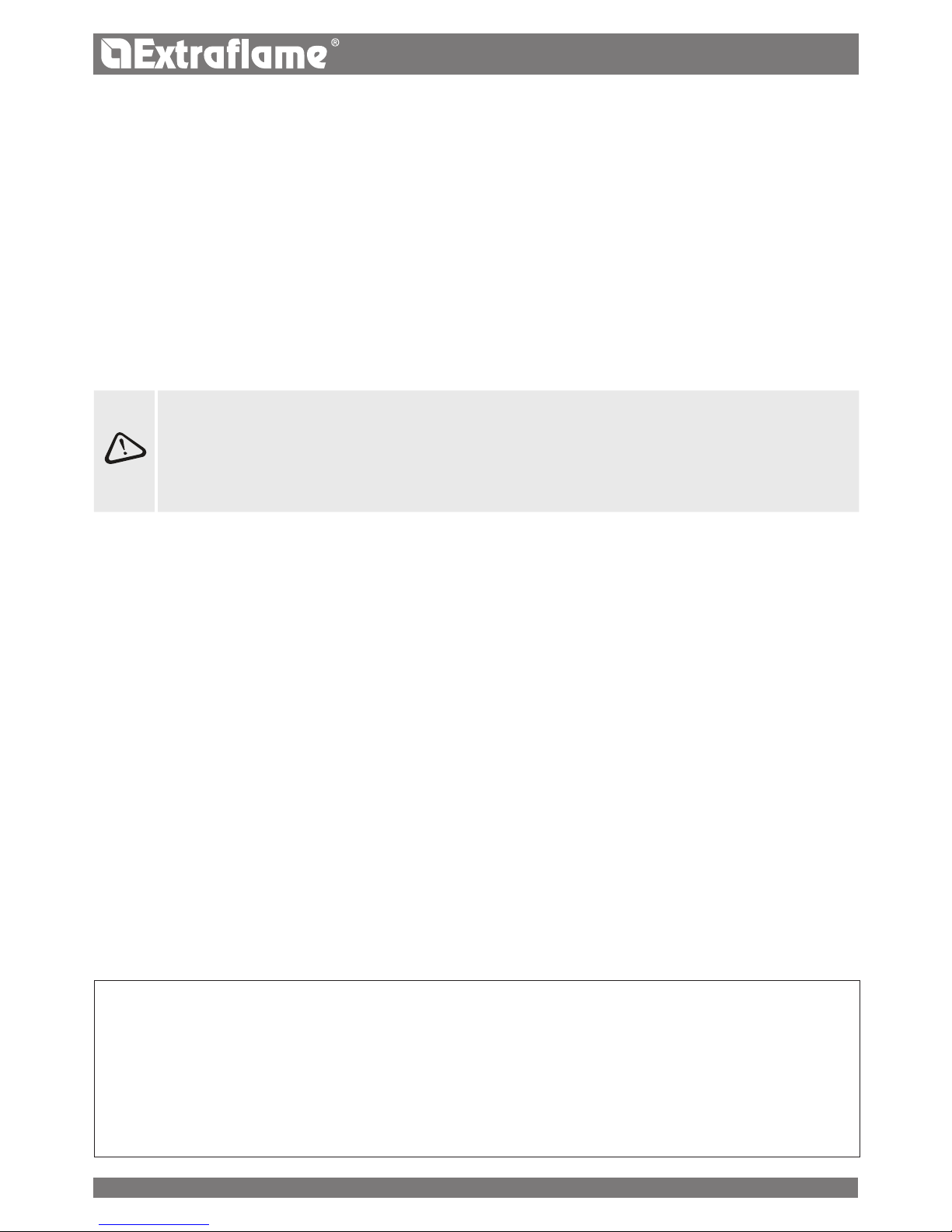
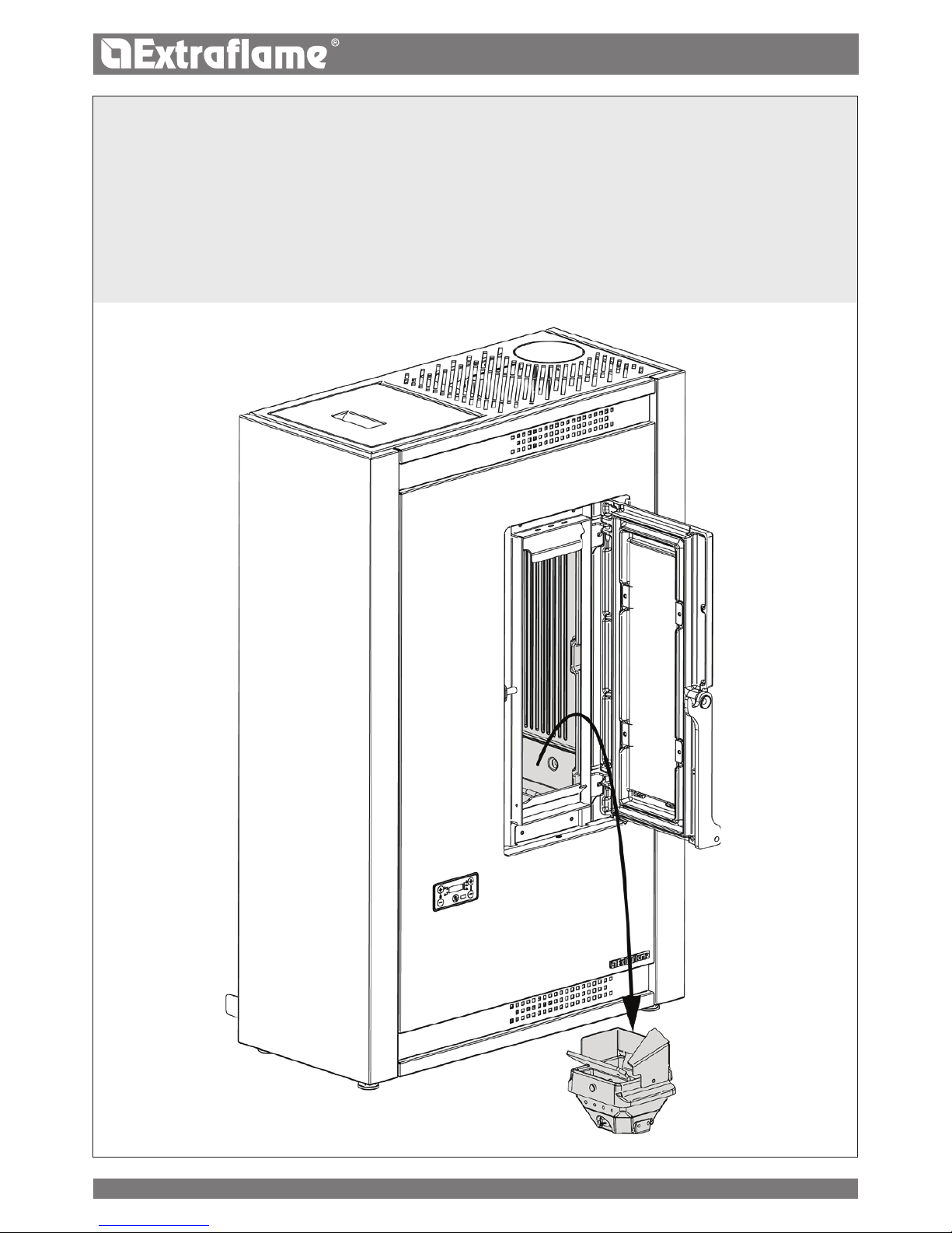
EVERY DAY
BURN POT AND COMBUSTION CHAMBER:
Vacuum the residue in the burn pot
Remove the burn pot completely from the relevant compartment;
Vacuum the ash from the burn pot slot, ignition plug pipe holder and combustion chamber.
Unblock all the holes in the burn pot using the poker supplied.
Re-position the burn pot in its slot and push it towards the re wall.
NOTE: Use a suitable ash vacuum cleaner with a special separate
container for the ashes collected
Page 26
26
ENGLISH
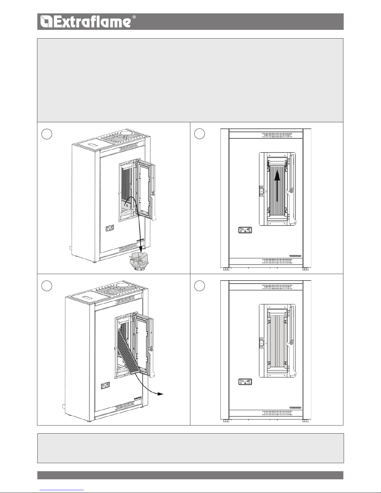
EVERY 30 DAYS
Cleaning "T" tting with inspection cap outside the stove: check and clean at least once a month
EVERY 30 DAYS
CLEANING THE TUBE HEAT EXCHANGER
Vacuum the residue in the burn pot
Remove the burn pot completely from the relevant
compartment (A);
Vacuum the ash from the burn pot slot, ignition plug pipe
holder and combustion chamber.
Unblock all the holes in the burn pot using the poker supplied.
Release the central wall of the replace from the clamps, by
sliding it upwards (B).
Remove the cast-iron wall by tilting it (C).
Once the central cast iron wall has been removed, clean the
tube heat exchanger (D).
After cleaning, replace the cast iron re wall and reposition the burn
pot in its slot pushing it towards the re wall.
NOTE: Use a suitable ash vacuum cleaner with a specic container
for separation of the ash collected.
A
B
C D
Page 27
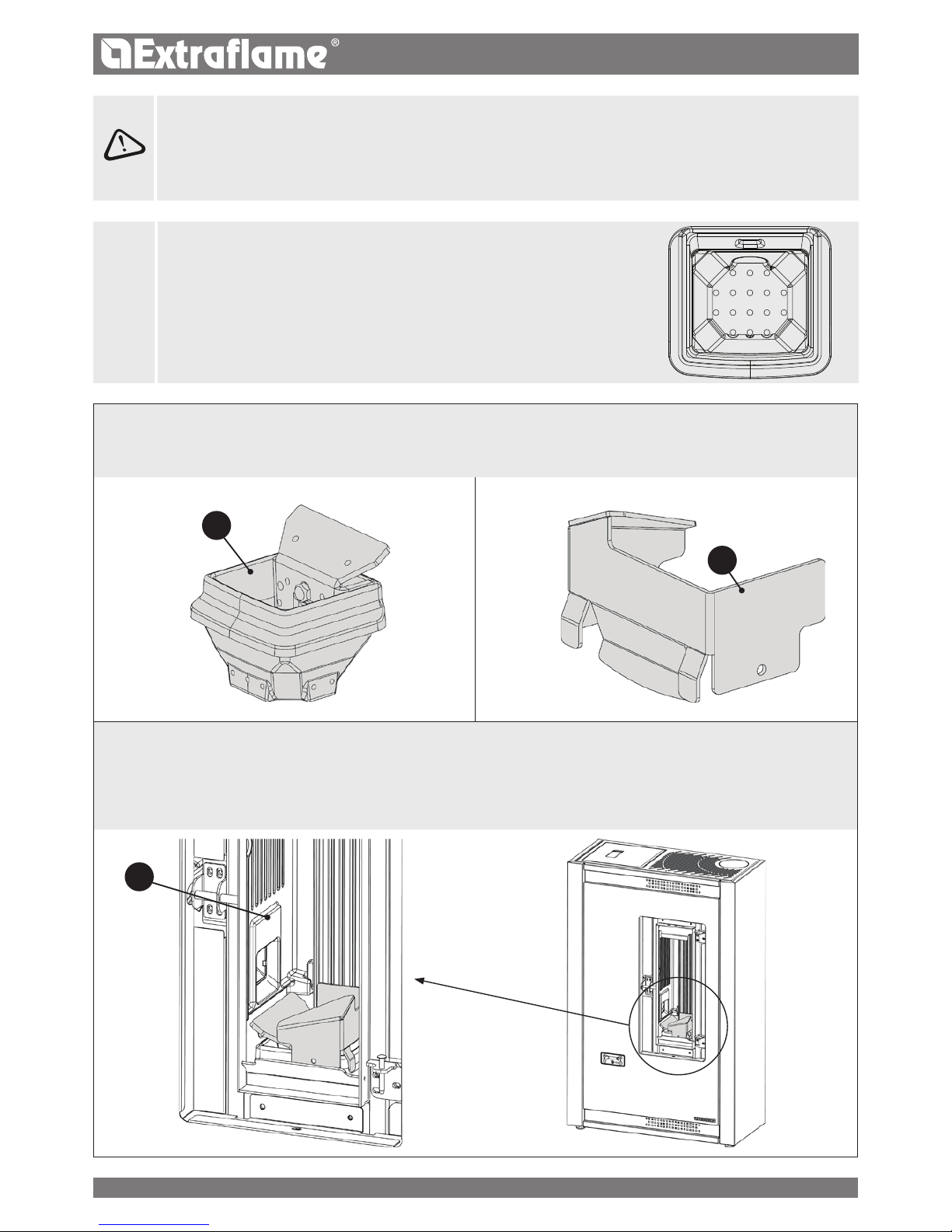
A
B
27
ENGLISH
J
A CLEAN BURN POT GUARANTEES CORRECT OPERATION!
BY MAKING SURE THE BURN POT AND ITS HOLES ARE ALWAYS CLEAN FROM
ANY COMBUSTION RESIDUE, EXCELLENT COMBUSTION BY THE GENERATOR IS
GUARANTEED OVER TIME, PREVENTING ANY MALFUNCTIONING THAT COULD
REQUIRE TECHNICIAN INTERVENTIONS.
THE "EASY SETUP" FUNCTION IN THE USER MENU CAN BE USED TO ADAPT
COMBUSTION ON THE BASIS OF THE NEEDS DESCRIBED.
BURN POT DETAIL
The burn pot consists of several parts:
The burn pot + partition (A) where combustion takes place physically and a ame guard (B).
When cleaning and removing the burn pot, remove the ame guard (B) by lifting it.
Perform the same operation in reverse order to re-assemble.
After having re-positioned, always make sure:
• that the ame guard is resting correctly on the burn pot.
• that the burn pot has been pushed towards the re wall (D) (to the left).
THE GASKETS FOR THE PELLET HOPPER, BURN POT AND FIRE DOOR ENSURE THAT THE STOVE WORKS PROPERLY.
IT IS NECESSARY TO PERIODICALLY CHECK THEM; IF THEY SEEM TO BE WORN OR DAMAGED, THEY MUST BE REPLACED
IMMEDIATELY.
THESE OPERATIONS MUST BE CARRIED OUT BY A QUALIFIED TECHNICIAN.
D
Page 28

28
ENGLISH
IF THE POWER SUPPLY CABLE IS DAMAGED, IT MUST BE REPLACED BY THE AFTERSALES SERVICE OR BY A SIMILARLY
QUALIFIED PERSON, SO AS TO AVOID ALL RISKS.
ROUTINE MAINTENANCE PERFORMED BY QUALIFIED TECHNICIANS
Routine maintenance must be performed at least once a year.
Using pellets as solid fuel, the generator requires annual routine maintenance, which must be performed by a qualied technician, using
only original spare parts.
Failure to comply can jeopardise safety of the appliance and make the warranty null and void.
Respecting the frequencies of cleaning reserved for the user described in the use and maintenance manual, the generator is guaranteed
correct combustion over time, preventing any anomalies and/or malfunctioning that could require more interventions of the technician.
Requests for routine maintenance are not contemplated in the product warranty.
GASKETS: PELLET HOPPER LID, DOOR, ASH DRAWER AND BURN POT
The gaskets guarantee the tightness of the stove and its consequent good functioning.
They must be controlled periodically. They must be replaced immediately if they are worn or damaged.
These operations must be carried out by a qualied technician.
CONNECTION TO THE FLUE
Vacuum and clean the pipe that leads to the ue yearly or any time that it is necessary. If there are horizontal tracts, the residue must be
removed before it can prevent the passage of the fumes.
DECOMMISSIONING END OF SEASON
At the end of each season, before turning the stove o, it is advisable to empty the pellet hopper out completely, vacuum any residue of
pellets and dust.
Furthermore, please disconnect the generator from the mains electricity and, for greater safety especially in the presence of children,
remove the power supply cable.
Routine maintenance must be performed at least once a year.
TO FIND OUT WHERE YOUR NEAREST SERVICE CENTRE IS, CONTACT YOUR DEALER OR GO TO THE
WEBSITE:
WWW.LANORDICA-EXTRAFLAME.COM
Page 29
D
F
E
B
A
29
ENGLISH
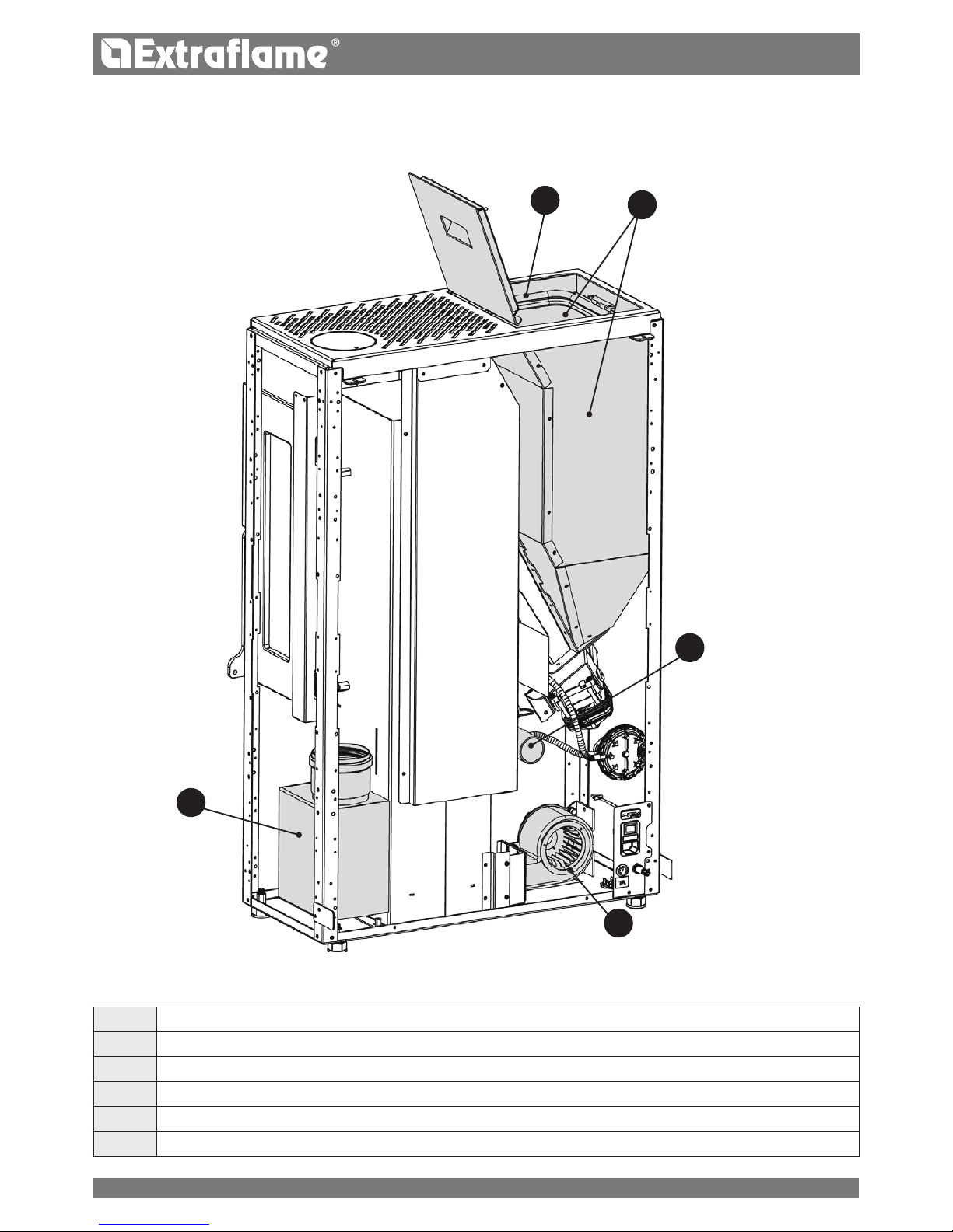
ROUTINE MAINTENANCE
THE IMAGES ARE FOR ILLUSTRATIVE PURPOSES ONLY.
THE IMAGES ARE FOR ILLUSTRATIVE PURPOSES ONLY.
A
Fumes motor (disassembly and cleaning and fumes and "T" pipes), new silicone or gasket in the points indicated.
B
Gaskets, pellet hopper and door (replace them and apply silicone where required)
C
Combustion chamber and heat exchanger (full cleaning) including ignition-plug pipe
D
Hopper (complete emptying and cleaning) and check gasket.
E
Check the air intake pipe and check/clean the mechanical pressure switch
F
Room air fan disassembly and removal of dust and pellet debris.
Page 30
D
C
B
A
F
B
C
30
ENGLISH
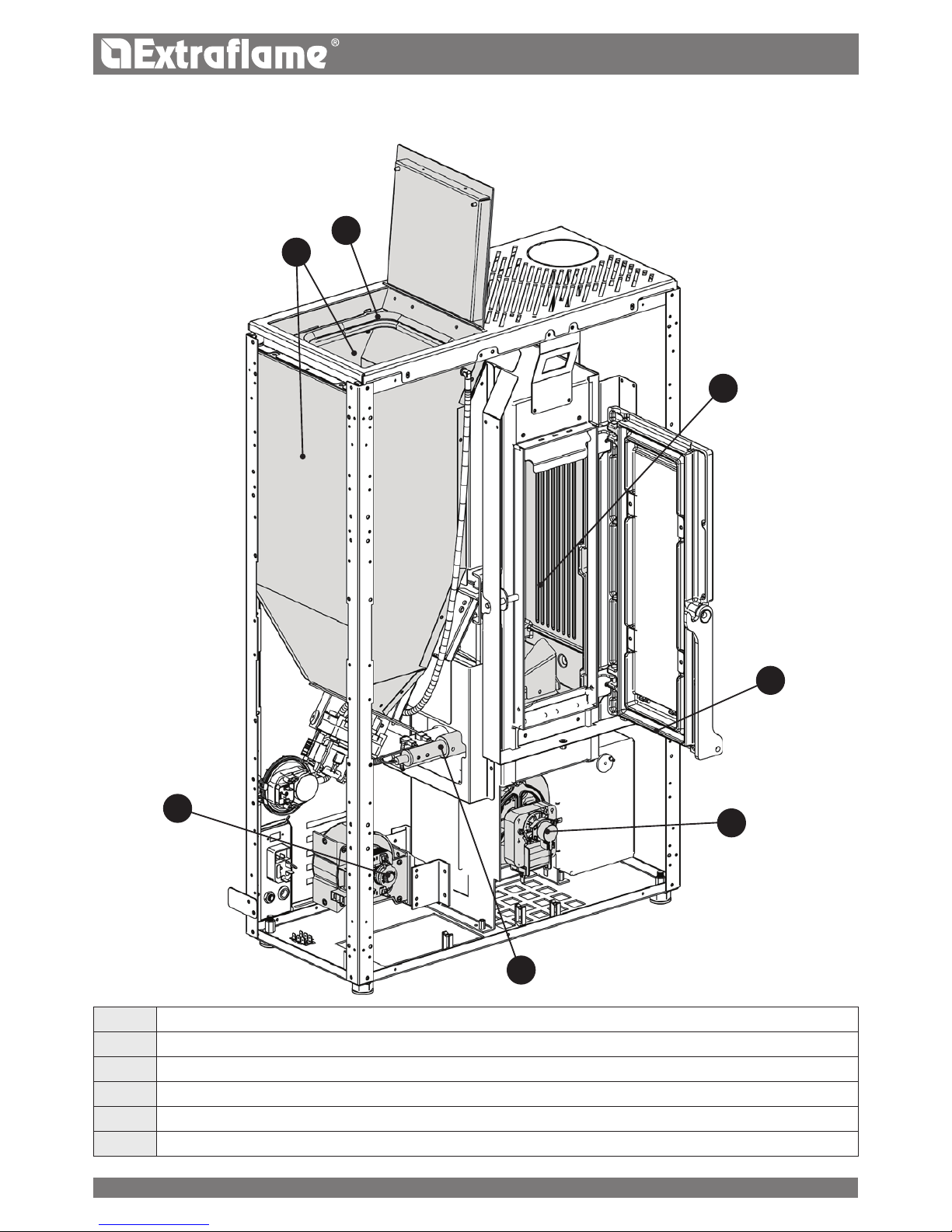
ROUTINE MAINTENANCE
THE IMAGES ARE FOR ILLUSTRATIVE PURPOSES ONLY.
A
Fumes motor (disassembly and cleaning and fumes and "T" pipes), new silicone or gasket in the points indicated.
B
Gaskets, pellet hopper and door (replace them and apply silicone where required)
C
Combustion chamber and heat exchanger (full cleaning) including ignition-plug pipe
D
Hopper (complete emptying and cleaning) and check gasket.
E
Check the air intake pipe and check/clean the mechanical pressure switch
F
Room air fan disassembly and removal of dust and pellet debris.
Page 31
31
ENGLISH
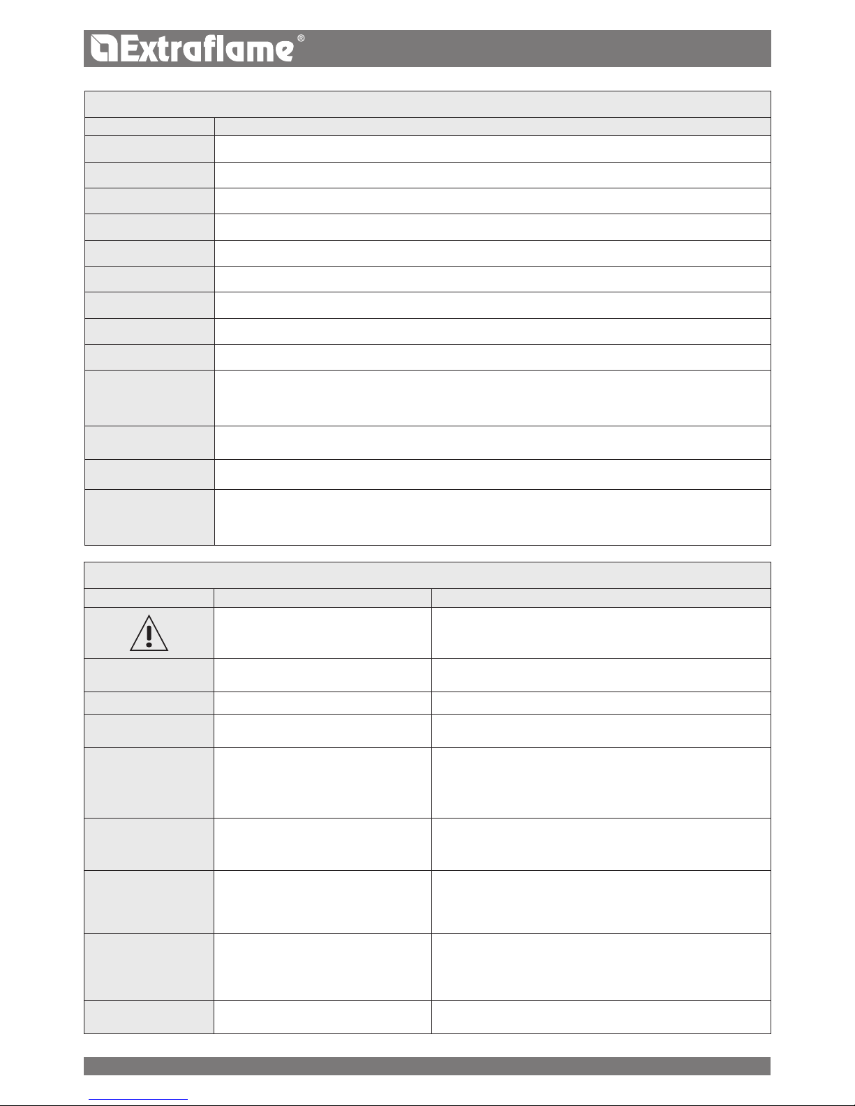
Displays
Display Reason
off
Generator o
sTaRT
The start-up phase is in progress
pelleT loaDinG
Continuous pellet feeding is in progress during the ignition phase
iGniTion
The ignition phase is in progress
pRepaRaTion
The preparation phase is in progress
WoRk
The normal work phase is in progress
MoDulaTion
The generator is working at minimum
final cleaninG
The nal cleaning is in progress
sTanD-by
Generator o waiting for re-ignition due to the external thermostat.
coolinG sTanD by
A new ignition is attempted when the generator has just been switched o. When the generator switches o, you must
wait for the complete shutdown of the fumes motor, then clean the burn pot. The generator can only be re-ignited when
these operations have been performed.
black ouT sTanD
by
The generator is cooling after a power cut.
Once cooling is completed, it will re-start automatically
auTo bloW
The automatic blow is active
seRvice
When this message appears, contact the technician authorised to perform routine maintenance on the stove. If the
cleaning is not performed, the message will appear at every start-up but without interrupting the normal operation of
the stove.
alaRMs
Display eXplanaTion soluTion
Indicates the presence of an alarm.
On: indicates the presence of an alarm.
The alarm can only be reset if the fumes motor has stopped and 15
minutes have passed since the alarm was displayed, by pressing key 1
for 3 seconds.
e00
Fumes motor fault Contact after-sales centre
e01
Fumes probe fault. Contact after-sales centre
e02
High fumes temperature
Check pellet feed (see “Easy”), if the problem cannot be solved, contact
an authorised technician.
e03
NO IGNITION
The pellet hopper is empty.
Pellet feed calibration inadequate.
Thermostat bulbs tripped.
Check for the presence of pellets in the hopper.
Adjust the pellet ow (see “Easy”).
Check the procedures described in the “Ignition” chapter.
Check the thermostats with bulbs (see chapter on Resetting)
e04
NO FLAME
The pellet hopper is empty.
No pellet feed.
The gearmotor does not feed pellets.
Check for the presence of pellets in the hopper.
Adjust the pellet ow (see “Easy”).
e05
DEPR ALARM
The door is not closed correctly.
The ash drawer is not closed correctly.
The combustion chamber is dirty.
The fumes exhaust pipe is blocked/dirty.
Check hermetic door closure.
Check hermetic closure of the ash drawer.
Check cleanliness of the fumes pipe and the combustion chamber.
e06
NO IGNITION BLACK OUT
No current during the ignition phase.
Turn the stove off using key 1 and repeat the procedure described in
the "Ignition" chapter.
Other reset operations should be performed by an authorised
technician.
e07
Triac
Abnormal pellet loading.
Contact after-sales centre
Page 32

32
ENGLISH
1. Extraame S.p.A. products are guaranteed, within the European community, for 24 months from the date of purchase.
Purchase has to be proved by means of a valid scal document issued by the seller (receipt, invoice or shipment document) identifying the
purchased product and its purchase and/or delivery date.
WARNING: This conventional guarantee does not replace the guarantee regulated by the European legislation on consumer rights.
The conventional guarantee is only applicable to the Italian region and to those areas, within the European Community, where the Authorised
Technical Assistance Centres are active (see the www.lanordica-extraame.com website)
It is also limited to the state of residence of the consumer, which must coincide with the premises and/or registered oce of the seller of the
Extraame S.p.A. product
These regulations do not apply if the product is purchased within commercial, entrepreneurial, or professional circumstances. In these cases
the product guarantee will be limited to a period of 12 months from the date of purchase.
ITALIAN GUARANTEE
What must be done if there is a product malfunction:
Consult the instructions manual to make sure the malfunction cannot be solved by using the product correctly. Make sure the malfunction is
included in those covered by the guarantee; otherwise the cost of the intervention will be borne entirely by the consumer. When requesting
the intervention of the Assistance service at the Authorised Assistance Centre, always specify: - type of malfunction - model of the appliance
- complete address - phone number
EUROPEAN GUARANTEE
What must be done if there is a product malfunction:
Consult the instructions manual to make sure the malfunction cannot be solved by using the product correctly. Make sure the malfunction
is included in those covered by the guarantee; otherwise the cost of the intervention will be borne entirely by the consumer. Request the
intervention of the Assistance service or the address of the Authorised Technical Assistance Centre to the seller; always specify: type of
malfunction, model of the appliance, complete address and phone number
If the malfunction arises in the rst 6 months of the product's life, the consumer has the right to have the product repaired with no expense.
From the seventh to the twenty-fourth month, if a malfunction arises, the consumer will bear the cost of the call, while the seller will pay for the
manpower and for any spare parts used.
2. If the malfunction is linked to external events and/or conditions such as, including but not limited to, insucient capacity of the systems;
wrong installation and/or maintenance by the personnel which hasn't got the skills prescribed by the laws of the country of residence of
the consumer; negligence; inability to use the product and wrong maintenance by the consumer, with respect to what is reported and
recommended by the instructions manual of the product, which is part of the sales contract, this guarantee will be void.
Damage to the product that cannot be related to manufacturing defects are also not included in this guarantee. Similarly are excluded defects
related to incorrect operation of the ue, according to the legislation in force in the country at the moment of purchase. Other exclusions
include all product defects due to carelessness, accidental breakdown, tampering and/or damage during transport (scratches, dents, etc.),
interventions carried out by unauthorised personnel and further damage caused by incorrect interventions by the consumer trying to arrange
the initial malfunction.
The following consumables are excluded by the guarantee: gaskets, ceramic or tempered glasses, cast iron grilles or coatings, refractory
materials (e.g. Nordiker or others), painted, chrome-plated or golden parts, majolica ware, handles, the brazier and its related components.
For Idro products the heat exchanger is not covered by the guarantee if a suitable condensation-proof circuit is not set up to ensure a return
temperature of the device of at least 55°C. The guarantee excludes all the external components on which the consumer can directly operate
during use and/or maintenance or that can be subject to wear and/or rust and stains on steel due to aggressive detergents.
If malfunctions are signalled which are not later conrmed during check by an authorised technician, the cost of the intervention will be borne
entirely by the consumer.
3. If it is not possible to restore product conformity by repairing it, the product/component will be replaced, the guarantee expiration date and
conditions will remain the same established when the product/component to be replaced has been purchased.
4. Extraame S.p.A. cannot be held liable for injury or damage which may - either directly or indirectly - be caused to persons, animals
and property ensuing from failure to observe all the instructions provided in the relevant instruction manual and the warnings regarding
installation, use and maintenance of the product, that can also be downloaded on the website.
5. Interventions for adjusting and/or regulating the product for the type of fuel or other reasons are excluded by the guarantee.
6. If the product is repaired in one of the Authorised Technical Assistance Centres indicated by Extraame S.p.A. and if the product is replaced,
transport will be free of charge. If the technician can repair the product at the user's place of residence and they refuse, transport to the
workshop and redelivery will be paid by the consumer.
7. After the 24 months of the guarantee have elapsed any repair intervention cost will be completely borne by the consumer.
8. In the case of disputes the only competent court is that of the Extraame S.p.A. registered oce - (Vicenza-Italy)
GUARANTEE TERMS
Page 33

33
ENGLISH
AddITIONAL wARNINGs
Only use the fuel recommended by the manufacturer. The product must not be used as an incinerator.
Do not use the product as a ladder or supporting structure.
Do not place laundry on the product to dry it. Any clothes-horse or similar objects must be kept at due distance from the product.
Danger of re or damage to the coating.
The user is fully liable for any incorrect use of the product. The manufacturer bears no civil or criminal liability for incorrect use.
Unauthorised tampering of any nature or replacement of spare parts of the product with non-original parts may endanger the operator
and the manufacturer bears no civil or criminal liability for this.
Large parts of the surface of the product can get very hot (door, handle, glass, smoke outlet pipes, etc.). Please therefore avoid coming
into contact with these parts without wearing suitable protective clothing or using appropriate measures, such as heat protective gloves.
DO NOT use the product with the door open or if the glass is broken.
The product must be electrically connected to a system equipped with an operational earthing system.
Turn o the product in the event of a failure or malfunctioning.
Unburned pellets that build up in the burner following each failed start-up must be removed before attempting to start up the product
again. Make sure that the burner is clean and correctly positioned before starting it up again.
Do not wash the product with water. Water may penetrate into the unit and cause faults in the electrical insulation. This can cause
electric shocks.
Installations not complying with the regulations in force, as well as incorrect use and failure to comply with the maintenance scheduled
by the manufacturer, will invalidate the guarantee.
Page 34

34
ENGLISH
Page 35

35
ENGLISH
Page 36

004276847-001 - MAN.UT.LUISELLA
20/11/2017
MADE IN ITALY
design & production
Extraame S.p.A. Via Dell’Artigianato, 12 36030 - MONTECCHIO PRECALCINO (VI) - ITALY
+39.0445.865911 - +39.0445.865912 - info@extraame.it - www.lanordica-extraame.com
TO FIND THE SERVICE CENTRE NEAREST TO YOU
CONTACT YOUR DEALER OR CONSULT
THE SITE WWW.LANORDICA-EXTRAFLAME.COM
The manufacturer reserves the right to vary the characteristics and the data reported in this pamphlet at any
moment and without notice, in order to improve its products.
This manual, therefore, cannot be regarded as a contract towards other parties.
 Loading...