

LP30
004205236 Rev_001_250610
MANUALE UTENTE
USER MANUAL
MANUEL UTILASATEUR
BENUTZERHANDBUCH
MANUAL DEL USUARIO
MANUAL DO UTENTE
ITALIANO - ENGLISH -FRANCAIS - DEUTSCH - ESPAÑOL -
PORTUGUÊS

1
INDEX
AVVERTENZE E SICUREZZA ................................................4
CARATTERISTICHE ...............................................................5
DISPOSITIVI DI SICUREZZA E FUNZIONAMENTO ............6
GLOSSARIO ...........................................................................7
INSTALLAZIONE ..................................................................8
INSTALLAZIONI AMMESSE.......................................8
INSTALLAZIONI NON AMMESSE .............................8
CANALE DA FUMO O RACCORDI .............................8
CAMINO O CANNA FUMARIA SINGOLA .................8
COLLEGAMENTO DELL’APPARECCCHIO ALLA
CANNA FUMARIA .....................................................9
EVACUAZIONE DEI PRODOTTI DELLA
COMBUSTIONE ..........................................................9
COLLEGAMENTO A PRESE D’ARIA ESTERNE ..........9
RACCOMANDAZIONI DI SICUREZZA .......................9
REGOLAMENTAZIONI NAZIONALI, REGIONALI,
PROVINCIALI E COMUNALI ......................................9
COMIGNOLO ........................................................... 10
IL PELLET ............................................................................ 10
INSTALLAZIONE E DISPOSITIVI DI SICUREZZA IMPIANTO
IDRAULICO ......................................................................... 11
SICUREZZE PER IMPIANTO A VASO CHIUSO ....... 11
DISTANZE DEI DISPOSITIVI DI SICUREZZA
SECONDO LA NORMATIVA .................................... 11
IMPIANTO IDRAULICO ........................................... 11
VALVOLA MISCELATRICE TERMOSTATICA
OBBLIGATORIA .................................................... 12
DISPLAY: QUADRO COMANDI ......................................... 13
FUNZIONAMENTO ............................................................ 14
ACCENSIONE ........................................................... 14
LAVORO ................................................................... 14
SPEGNIMENTO ....................................................... 14
TERMOSTATO SUPPLEMENTARE STBY .............. 14
MENÙ .................................................................................. 15
REGOLAZIONE TEMPERATURA ............................ 16
REGOLAZIONE POTENZA ...................................... 16
MENÙ REGOLAZIONI UTENTE ................................ 17
REGOLAZIONE PELLET .......................................... 17
MODALITÀ AUTOMATICA/MANUALE .................. 17
MENÙ STATO ........................................................... 18
SET UTENTE ............................................................ 18
SET OROLOGIO ....................................................... 19
REGOLAZIONE CRONO ............................... 19
MENÙ SET LINGUA ...................................... 20
MENÙ SET SCAMBIATORE .......................... 21
TABELLA SEGNALAZIONI ................................................. 22
ALLARME ........................................................................... 22
TABELLA ALLARMI ............................................................ 23
PULIZIA BRACIERE ................................................. 24
CASSETTO CENERE LP30 ....................................... 24
GUARNIZIONI PORTA E CASSETTO CENERE ........ 24
PULIZIA DEL CAMINO ............................................ 24
PULIZIA CALDAIA ............................................................. 24
GARANZIA ......................................................................... 25
WARNINGS AND SAFETY DEVICES.................................. 28
FEATURES .......................................................................... 29
SAFETY AND FUNCTIONING DEVICES ............................ 30
GLOSSARY.......................................................................... 31
INSTALLATION .................................................................. 32
INSTALLATIONS ALLOWED ................................... 32
INSTALLATIONS NOT ALLOWED ........................... 32
SMOKE CHANNEL OR FITTINGS ........................... 32
CHIMNEY OR INDIVIDUAL FLUE ........................... 32
CONNECTION OF THE APPLIANCE TO THE FLUE 33
EVACUATION OF THE COMBUSTION PRODUCTS 33
CONNECTION TO EXTERNAL AIR INLETS ............. 33
SAFETY RECOMMENDATIONS .............................. 33
NATIONAL, REGIONAL, PROVINCIAL AND TOWN
COUNCIL REGULATIONS ....................................... 33
CHIMNEY CAP ......................................................... 34
THE PELLETS ...................................................................... 34
INSTALLATION AND HYDRAULIC PLANT SAFETY
DEVICES ............................................................................. 35
SAFETY DEVICES FOR CLOSED VESSEL SYSTEM 35
DISTANCES OF SAFETY DEVICES ACCORDING TO
THE STANDARD ...................................................... 35
HYDRAULIC PLANT ................................................ 35
AUTOMATIC THERMOSTATIC MIXER VALVE
MAN DATORY ........................................................ 36
DISPLAY: CONTROL BOARD ............................................. 37
FUNCTIONING ................................................................... 38
IGNITION ................................................................. 38
WORKING ................................................................ 38
SWITCHOFF ........................................................... 38
ADDITIONAL THERMOSTAT STBY ...................... 38
MENU .................................................................................. 39
TEMPERATURE REGULATION ................................ 40
POWER REGULATION ............................................. 40
USER REGULATIONS MENU .................................... 41
PELLET REGULATION ............................................. 41
AUTOMATIC/MANUAL MODE ............................... 41
STATE MENU ........................................................... 42
SET USER ................................................................. 42
SET CLOCK .............................................................. 43
CHRONO REGULATION ............................... 43
SET LANGUAGE MENU ................................ 44
SET HEAT EXCHANGER MENU .................... 45
SIGNS TABLE ...................................................................... 46
ALARM ................................................................................ 46
ALARMS TABLE .................................................................. 47
BURN POT CLEANING ............................................ 48
LP30 ASH DRAWER ................................................ 48
DOOR GASKET AND ASH DRAWER ...................... 48
CLEANING THE FLUE .............................................. 48
BOILER CLEANING ............................................................ 48
CARACTERISTIQUES ......................................................... 49
DISPOSITIFS DE SECURITE ET FONCTIONNEMENT ....... 50
GLOSSAIRE ......................................................................... 51
INSTALLATION ................................................................... 52
INSTALLATIONS ADMISES..................................... 52
INSTALLATIONS NON ADMISES ........................... 52
CANAL DE FUMEE OU RACCORDS ........................ 52
CHEMINEE OU TUYAU D'EVACUATION DES
FUMEES INDIVIDUELLE ......................................... 52
RACCORDEMENT DE L'APPAREIL AU TUYAU

2
D'EVACUATION DES FUMEES ................................ 53
EVACUATION DES PRODUITS DE LA COMBUSTION
53
BRANCHEMENT A PRISES D’AIR EXTERNES ........ 53
RECOMMANDATIONS DE SECURITE .................... 53
REGLEMENTATIONS NATIONALES, REGIONALES,
PROVINCIALES ET COMMUNALES ....................... 53
POT DE CHEMINEE ................................................. 54
LE PELLET ........................................................................... 54
INSTALLATION ET DISPOSITIFS DE SECURITE
INSTALLATION HYDRAULIQUE ........................................ 55
DISPOSITIFS DE SECURITE POUR INSTALLATION A
VASE FERME ............................................................ 55
DISTANCES DES DISPOSITIFS DE SECURITE
CONFORMEMENT A LA NORMATIVE .................... 55
INSTALLATION HYDRAULIQUE ............................. 55
VANNE MELANGEUSE THERMOSTATIQUE
OBLIGATOIRE ....................................................... 56
DISPLAY: TABLEAU DE COMMANDES ............................. 57
FONCTIONNEMENT .......................................................... 58
ALLUMAG E .............................................................. 58
TRAVAIL ................................................................... 58
ARRÊT ...................................................................... 58
THERMOSTAT SUPPLEMENTAIRE STBY ............ 58
MENU .................................................................................. 59
REGLAGE TEMPERATURE ...................................... 60
REGLAGE PUISSANCE ............................................ 60
MENU REGLAGES UTILISATEUR ............................. 61
REGLAGE DU PELLET ............................................. 61
MODE AUTOMATIQUE/MANUEL .......................... 61
MENU ETAT ............................................................. 62
SET UTILISATEUR ................................................... 62
SET HORLOGE ......................................................... 63
REGLAGE CHRONO...................................... 63
MENU SET LANGUE ..................................... 64
MENU SET ECHANGEUR ............................. 65
TABLEAU DES SIGNALISATIONS ...................................... 66
ALARME ............................................................................. 66
TABLEAU DES ALARMES .................................................. 67
NETTOYAGE BRASIER ............................................ 68
TIROIR A CENDRES LP30 ....................................... 68
JOINTS D'ETANCHEITE PORTE ET TIROIR A
CENDRES ................................................................. 68
NETTOYAGE DE LA CHEMINEE .............................. 68
NETTOYAGE DE LA CHAUDIERE ....................................... 68
EIGENSCHAFTEN ............................................................... 69
SICHERHEITSEINRICHTUNGEN UND FUNKTION ........... 70
GLOSSAR ............................................................................ 71
INSTALLATION .................................................................. 72
ZULÄSSIGE INSTALLATIONEN .............................. 72
UNZULÄSSIGE INSTALLATIONEN ......................... 72
RAUCHGASKANAL BZW. ANSCHLÜSSE ............... 72
SCHORNSTEIN ODER EINZELRAUCHGASROHR .. 72
ANSCHLUSS DES GERÄTES AN DEN SCHORNSTEIN
73
ABFÜHRUNG DER VERBRENNUNGSPRODUKTE . 73
ANSCHLUSS AN ÄUSSERE ZULUFTLEITUNGEN .. 73
SICHERHEITSEMPFEHLUNGEN ............................. 73
VORSCHRIFTEN AUF LANDES, REGIONAL,
PROVINZ UND GEMEINDEEBENE ........................ 73
SCHORNSTEINKOPF............................................... 74
DAS PELLET ....................................................................... 74
INSTALLATION UND SICHERHEITSVORRICHTUNGEN DER
WASSERLEITUNGEN ......................................................... 75
SICHERHEITSEINRICHTUNGEN FÜR ANLAGE MIT
GESCHLOSSENEM AUSDEHNUNGSGEFÄSS ........ 75
VORSCHRIFTSGEMÄSSE ABSTÄNDE DER
SICHERHEITSVORRICHTUNGEN ........................... 75
HYDRAULIKANLAGE .............................................. 75
AUTOMATISCHES THERMOSTATMISCHVENTIL
VERBINDLICH ....................................................... 76
DISPLAY: BEDIENTAFEL .................................................... 77
BETRIEB .............................................................................. 78
ZÜNDUNG ............................................................... 78
HEIZBETRIEB........................................................... 78
AUSSCHALTEN ........................................................ 78
ZUSATZTHERMOSTAT STBY ............................... 78
MENÜ .................................................................................. 79
TEMPERATURREGELUNG ...................................... 80
REGELUNG DER LEISTUNG .................................... 80
MENÜ BENUTZEREINSTELLUNGEN ...................... 81
EINSTELLUNG DER PELLETZUFUHR .................... 81
BETRIEBSART AUTOMATIK/MANUELL ................ 81
STATUSMENÜ ........................................................ 82
USEREINSTELLUNGEN.......................................... 82
SET UHR ................................................................... 83
EINSTELLUNG CHRONO.............................. 83
MENÜ SPRACHE EINSTELLEN .................... 84
MENÜ WTAUSCHEREINSTELL. .................. 85
TABELLE DER MELDUNGEN ............................................. 86
ALARM ................................................................................ 86
TABELLE DER ALARME ..................................................... 87
REINIGUNG DER BRENNSCHALE .......................... 88
ASCHENKASTEN LP30 ........................................... 88
DICHTUNGEN VON TÜR UND ASCHENKASTEN .. 88
REINIGUNG DES SCHORNSTEINS ......................... 88
REINIGUNG DES HEIZKESSELS ........................................ 88
CARACTERÍSTICAS ............................................................ 89
DISPOSITIVOS DE SEGURIDAD Y FUNCIONAMIENTO .. 90
GLOSARIO .......................................................................... 91
INSTALACIÓN .................................................................... 92
INSTALACIONES ADMITIDAS ................................ 92
INSTALACIONES NO ADMITIDAS ......................... 92
CANAL DE HUMO O RACORES .............................. 92
CHIMENEA O CONDUCTO DE SALIDA DE HUMOS
INDIVIDUAL ............................................................ 92
CONEXIÓN DEL APARATO AL CONDUCTO DE
SALIDA DE HUMOS ............................................... 93
EVACUACIÓN DE LOS PRODUCTOS DE LA
COMBUSTIÓN ......................................................... 93
CONEXIÓN A TOMAS DE AIRE EXTERNAS ........... 93
RECOMENDACIONES DE SEGURIDAD .................. 93
REGLAMENTOS NACIONALES, REGIONALES,
PROVINCIALES Y MUNICIPALES ........................... 93
SOMBRERETE .......................................................... 94
EL PELLET ........................................................................... 94
INSTALACIÓN Y DISPOSITIVOS DE SEGURIDAD DEL
SISTEMA HIDRÁULICO...................................................... 95

3
DISPOSITIVOS DE SEGURIDAD PARA LA
INSTALACIÓN CON VASO CERRADO .................... 95
DISTANCIAS DE LOS DISPOSITIVOS DE
SEGURIDAD SEGÚN LA NORMATIVA ................... 95
INSTALACIÓN HIDRÁULICA .................................. 95
VÁLVULA MEZCLADORA TERMOSTÁTICA
OBLIGATORIA ....................................................... 96
PANTALLA: CUADRO DE MANDOS .................................. 97
FUNCIONAMIENTO ........................................................... 98
ENCENDIDO ............................................................ 98
TRAB AJO ................................................................. 98
APAGADO ................................................................ 98
TERMOSTATO SUPLEMENTARIO STBY .............. 98
MENÚ .................................................................................. 99
REGULACIÓN DE LA TEMPERATURA .................. 100
REGULACIÓN DE LA POTENCIA .......................... 100
MENÚ REGULACIONES DEL USUARIO .................101
REGULACIÓN PELLET .......................................... 101
MODO AUTOMÁTICO/MANUAL .......................... 101
MENÚ ESTADO ...................................................... 102
SET USUARIO ........................................................ 102
SET RELOJ ............................................................. 103
REGULACIÓN CRONO ............................... 103
MENÚ SET IDIOMA .................................... 104
MENÚ SET INTERCAMBIADOR ................. 105
TABLA DE INDICACIONES .............................................. 106
ALAR MA ........................................................................... 106
TABLA ALARMAS ............................................................ 107
LIMPIEZA BRASERO ............................................. 108
CENICERO LP30 .................................................... 108
JUNTAS DE LA PUERTA Y CENICERO ..................108
LIMPIEZA DE LA CHIMENEA ............................... 108
LIMPIEZA DE LA CALDERA ............................................. 108
CARACTERÍSTICAS .......................................................... 109
DISPOSITIVOS DE SEGURANÇA E FUNCIONAMENTO 110
GLOSSÁRIO ...................................................................... 111
INSTALAÇÃO ................................................................... 112
INSTALAÇÕES PERMITIDAS ................................ 112
INSTALAÇÕES NÃO PERMITIDAS ....................... 112
CONDUTA DE FUMOS OU LIGAÇÕES ................. 112
CHAMINÉ OU CONDUTA DE EVACUAÇÃO DE
FUMOS INDIVIDUAL ............................................ 112
LIGAÇÃO DO APARELHO À CONDUTA DE
EVACUAÇÃO DE FUMOS ..................................... 113
EVACUAÇÃO DE PRODUTOS DE COMBUSTÃO .. 113
LIGAÇÃO ÀS ENTRADAS EXTERNAS DE AR ....... 113
RECOMENDAÇÕES DE SEGURANÇA .................. 113
REGULAMENTAÇÕES NACIONAIS, REGIONAIS,
PROVINCIAIS E MUNICIPAIS ............................... 113
CONE DE CHAMINÉ .............................................. 114
OS PELLETS ...................................................................... 114
INSTALAÇÃO E DISPOSITIVOS DE SEGURANÇA DO
SISTEMA HIDRÁULICO.................................................... 115
SEGURANÇA PARA SISTEMA COM VASO FECHADO
115
DISTÂNCIAS DOS DISPOSITIVOS DE SEGURANÇA
DE ACORDO COM A NORMATIVA .......................115
SISTEMA HIDRÁULICO ......................................... 115
VÁLVULA MISTURADORA TERMOSTÁTICA
OBRIGATÓRIA .................................................... 116
ECRÃ: QUADRO DE COMANDOS ................................... 117
SATURDAY ............................................................. 117
FUNCIONAMENTO .......................................................... 118
ACENDIMENTO ..................................................... 118
TRABALHO ............................................................ 118
DESCONEXÃO ....................................................... 118
TERMÓSTATO SUPLEMENTAR STBY ................ 118
MENU ................................................................................ 119
REGULAÇÃO DA TEMPERATURA ........................ 120
REGULAÇÃO DA POTÊNCIA ................................ 120
MENU REGULAÇÕES DO UTENTE ........................ 121
REGULAÇÃO DE PELLET ...................................... 121
MODALIDADE AUTOMÁTICA/MANUAL ............. 121
MENU ESTADO ...................................................... 122
SET USUÁRIO ........................................................ 122
SET RELÓGIO ........................................................ 123
REGULAÇÃO CRONO ................................. 123
MENU SET IDIOMA .................................... 124
MENU SET PERMUTADOR......................... 125
TABELA DE SINALIZAÇÕES ............................................ 126
ALARME ........................................................................... 126
TABELA DE ALARMES .....................................................127
LIMPEZA DA FORNALHA ..................................... 128
GAVETA PARA CINZAS LP30 ............................... 128
GUARNIÇÕES DA PORTA E GAVETA DE CINZAS 128
LIMPEZA DA CHAMINÉ ........................................ 128
LIMPEZA DA CALDEIR .................................................... 128

AVVERTENZE E SICUREZZA
4
Vi ringraziamo per aver scelto la nostra azienda; il nostro prodotto è un’ottima soluzione di riscaldamento nata dalla tecnologia più
avanzata con una qualità di lavorazione di altissimo livello ed un design sempre attuale, al ne di farVi godere sempre in assoluta sicurezza
la fantastica sensazione che il calore della amma può darVi.
Tutti la gamma dei prodotti è costruita secondo le direttive:
89/106 CEE (Prodotti da Costruzione),89/366 CEE (Direttiva EMC),,2004/108 CE (Direttiva EMC), 2006/95 CE (Direttiva
Bassa Tensione),EN 14785, EN 60335-1,EN 60335-2-102,,EN 61000-3-2,EN 61000-3-3,EN 50366,EN 55014-1, EN 55014-2,
EN 303 - 5, EN 13240
Le caldaie prodotte nel nostro stabilimento vengono costruite
facendo attenzione anche ai singoli componenti in modo da
proteggere sia l’utente sia l’installatore da eventuali incidenti. Si
raccomanda quindi al personale autorizzato, dopo ogni intervento
e ettuato sul prodotto, di prestare particolare attenzione ai
collegamenti elettrici, soprattutto per quanto riguarda la parte
spellata dei conduttori che non deve uscire in alcun modo dalla
morsettiera, evitando così il possibile contatto con le parti vive del
conduttore.L’installazione deve essere eseguita da personale
qualificato e/o assistenza tecnica del costruttore, che dovrà
rilasciare all’acquirente una dichiarazione di conformità
dell’impianto, il quale si assumerà l’intera responsabilità
dell’installazione definitiva e del conseguente buon
funzionamento del prodotto installato. E’ necessario tenere in
considerazione anche tutte le leggi e le normative nazionali,
regionali, provinciali e comunali presenti nel paese in cui
è stato installato l’apparecchio.Non vi sarà responsabilità
da parte del costruttore in caso di mancato rispetto di tali
precauzioni.
Il presente manuale di istruzione costituisce parte integrante del
prodotto: assicurarsi che sia sempre a corredo dell’apparecchio,
anche in caso di cessione ad un altro proprietario o utente oppure
di trasferimento su altro luogo. In caso di suo danneggiamento o
smarrimento richiedere un altro esemplare al servizio tecnico di
zona.Questa caldaia deve essere destinata all’uso per il quale è
stata espressamente realizzata. E’ esclusa qualsiasi responsabilità
contrattuale ed extracontrattuale del costruttore per danni
causati a persone, animali o cose, da errori di installazione,
di regolazione di manutenzione e da usi impropri.Dopo aver
tolto l’imballo, assicurarsi dell’integrità e della completezza del
contenuto. In caso di non rispondenza, rivolgersi al rivenditore da
cui è stato acquistato l’apparecchio.Tutti i componenti elettrici che
costituiscono la caldaia, garantendone il corretto funzionamento,
dovranno essere sostituiti con pezzi originali esclusivamente da
un centro di assistenza tecnica autorizzato.La manutenzione
della caldaia deve essere eseguita almeno una volta all’anno,
programmandola per tempo con il personale qualificato e/o
assistenza tecnica del costruttore.
Per la sicurezza è bene ricordare che:
E’ vietato l’uso della caldaia da parte di persone (inclusi
bambini) con capacità siche, sensoriali e mentali ridotte, o
inesperte, a meno che non vengano supervisionate ed istruite
nell’uso dell’apparecchio da una persona responsabile per la
loro sicurezza.
I bambini devono essere controllati per assicurarsi che non
giochino con l’apparecchio.
Non toccare la caldaia se si è a piedi nudi e con parti del
corpo bagnate o umide.
E’ vietato modi care i dispositivi di sicurezza o di regolazione
senza l’autorizzazione o le indicazioni del costruttore.
Non tirare, staccare, torcere i cavi elettrici fuoriuscenti dalla
caldaia anche se questa è scollegata dalla rete di alimentazione
elettrica.
Si raccomanda di posizionare il cavo di alimentazione
in modo che non venga in contatto con parti calde
dell’apparecchio.
La spina di alimentazione deve risultare accessibile dopo
l’installazione.
Evitare di tappare o ridurre dimensionalmente le aperture
di aerazioni del locale di installazione, le aperture di aerazione
sono indispensabili per una corretta combustione.
Non lasciare gli elementi dell’imballo alla portata dei
bambini o di persone inabili non assistite.
Durante il normale funzionamento del prodotto la porta
del focolare deve rimanere sempre chiusa.
Evitare il contatto diretto con parti dell’apparecchio che
durante il funzionamento tendono a surriscaldarsi.
Controllare la presenza di eventuali ostruzioni prima di
accendere l’apparecchio in seguito ad un lungo periodo di
mancato utilizzo.
La caldaia è stata progettata per funzionare con qualsiasi
condizione climatica (anche critica), in caso di condizioni
particolarmente avverse (vento forte, gelo) potrebbero
intervenire sistemi di sicurezza che portano la caldaia in
spegnimento.Se si veri ca ciò contattare il servizio di assistenza
tecnica e, in ogni caso, non disabilitare i sistemi di sicurezza.
In caso di incendio della canna fumaria munirsi di adeguati
sistemi per so ocare le amme o richiedere l’intervento dei
vigili del fuoco.
Questo apparecchio non deve essere utilizzato come
inceneritore di ri uti
Non utilizzare alcun liquido in ammabile per l’accensione
In fase di riempimento non portare il sacco di pellet a
contatto con il prodotto
Congratulazioni!
AVVERTENZE E SICUREZZA
ITALIANO
1
2
5
3
4
6
7
8
0,0 0,5 1,0 1,5 2,0 2,5
0
1
2
3
4
5
6
kg
333
mm
1406
mm
875
mm
772
mm
120
mm
60
kW
33.8
kW
31.1
kW
10.0
kW
8.6
kg/h
7.0
kg/h
2.0
kg
~ 85
Pa
~ 10
W
470
W
470
Vac
230
Hz
50
“
1
“
1/2
m
5
bar
2.5
bar
0.6
CARATTERISTICHE
5
CARATTERISTICHE
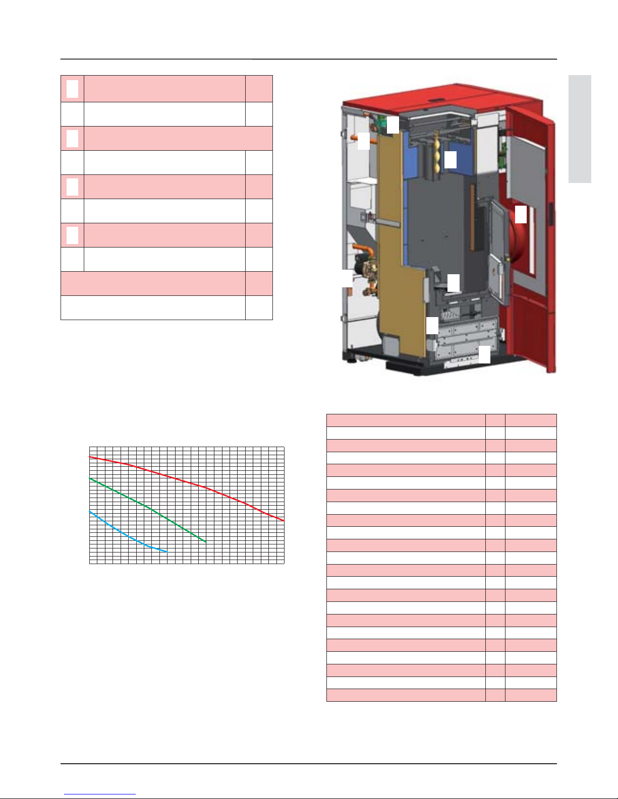
Il gra co riportato sotto illustra il comportamento del circolatore
utilizzato sui nostri termoprodotti alle velocità impostabili.
1
Circolatore integrato nel
termoprodotto con prevalenza 5 m
si
2
Volume vaso espansione integrato nel
termoprodotto (l)
12
3
Braciere
4
Meccanismo di pulizia automatica si
5
Turbolatore pulizia fascia tubiera si
6
Valvola sicurezza 3 bar integrata nel
termoprodotto
si
7
Pressostato di minima e massima
integrato nel termoprodotto
si
8
Cassetto cenere si
Contenuto d’acqua scambiatore (l) 66
Massimo contenuto d’acqua dell’impianto per
vaso di espansione integrato (l)
170
Prevalnza (m)
Portata (m3/h)
Prove eseguite usando come combustibile pellet di legno
certi cato secondo la ONORM M7135 DIN PLUS.
I dati sopra riportati sono indicativi e non impegnativi. L’azienda
produttrice si riserva la facoltà di apportare qualsiasi modi ca
allo scopo di migliorare le prestazioni del prodotto.
Peso
Altezza
Larghezza
Profondità
Diametro tubo scarico fumi
Diametro tubo aspirazione aria
Potenza termica globale max
Potenza termica utile max (resa all’acqua)
Potenza termica globale min
Potenza termica utile min
Consumo orario combustibile max
Consumo orario combustibile min
Capacità serbatoio
Tiraggio del camino consigliato
Potenza elettrica nominale
Potenza elettrica apparecchio
Tensione nominale
Frequenza nominale
Diametro tubo entrata/uscita acqua
Diametro tubo scarico automatico
Prevalenza pompa
Max pressione idrica di esercizio ammessa
Min pressione idrica di esercizio ammessa

DISPOSITIVI DI SICUREZZA E FUNZIONAMENTO
6
DISPOSITIVI DI SICUREZZA E FUNZIONAMENTO
DISPOSITIVO DI SICUREZZA LP30
Scheda elettronica: interviene direttamente mandando in allarme il prodotto no al
completo ra reddamento nel caso di: rottura motore fumi, rottura motore caricamento
pellet, black out (se superiore 10 secondi), mancata accensione
*
Micro porta: Con la porta aperta viene bloccato il funzionamento del sistema di pulizia del
braciere
*
Pressotato elettronico: in caso di pressione (lato aria) inadeguata porta la macchina in
allarme
*
Fusibile 2.5 A : proteggono la macchina da sovracorrenti
2.5 A 250V
F (rapido)
Bulbo meccanico tarato 85°C a riarmo manuale: interviene bloccando il carico di
combustibile qual’ora la t° del serbatoio del pellet raggiunga il limite di 85°C. Il riarmo deve
essere eseguito da personale quali cato e/o assistenza tecnica del costruttore
*
Bulbo meccanico tarato 100°C a riarmo manuale: interviene bloccando il carico di
combustibile qual’ora la t° acqua interna al prodotto sia prossima ai 100° . Il riarmo deve
essere eseguito dopo il completo ra reddamento della caldaia
*
Pressostato di massima: installato in serie nell’ alimentazione di energia elettrica al motore
pellet. Se la pressione nell’impianto supera i 2.5 bar, scatta il riarmo manuale del pressostato:
Il riarmo deve essere eseguito da personale quali cato e/o assistenza tecnica del
costruttore
*
Pressostato di minima: se la pressione nell’impianto è troppo bassa (minore di 0.6 bar) la
caldaia va in allarme pressione minima
*
TABELLA DEI DISPOSITIVI DI SICUREZZA PER IMPIANTO A VASO CHIUSO PRESENTI E NON PRESENTI NEL PRODOTTO
Valvola di sicurezza *
Termostato di comando del circolatore *
Indicatore di temperatura *
Termostato di attivazione dell’allarme acustico -
Interruttore termico automatico di regolazione ( rmware scheda) *
Interrutore termico automatico di blocco (termostato di blocco) sovratemperatura
acqua
*
Sistema di circolazione *
Sistema di espansione *
Sistema di dissipazione di sicurezza incorporato al generatore con
valvola di scarico termico (autoazionata), qualora l’apparecchiatura
non sia provvista di un sistema di autoregolazione della temperatura.
Non necessario in quanto la
macchina è provvista di un
sistema di autoregolazione
della t° e di un interruttore
termico automatico di
blocco.
Di serie (*)
Non di serie (-)

ITALIANO
GLOSSARIO
7
CANALE DA FUMO O RACCORDO
Condotto o elemento di collegamento tra apparecchio generatore di calore e camino per l’evacuazione dei prodotti della
combustione.
APPARECCHIO A FOCOLARE CHIUSO
Generatore la cui apertura è consentita solo per la carica del combustibile durante l’impiego.
BIOMASSA
Materiale di origine biologica, escluso il materiale incorporato in formazioni geologiche e trasformato in fossile.
BIOCOMBUSTIBILE
Combustibile prodotto direttamente o indirettamente da biomassa.
CAMINO
Condotto verticale avente lo scopo di raccogliere ed espellere, a conveniente altezza dal suolo, i prodotti della combustione
proveniente da un solo apparecchio.
COIBENTAZIONE
Insieme degli accorgimenti e materiali usati per impedire la trasmissione di calore attraverso una parete che divide ambienti a
temperatura diversa.
COMIGNOLO
Dispositivo posto alla sommità del camino atto a facilitare la dispersione in atmosfera dei prodotti della combustione.
CONDENSA
Prodotti liquidi che si formano quando la temperatura dei gas di combustione è minore o uguale al punto di rugiada
dell’acqua.
GENERATORI DI CALORE
Apparecchio che permette di produrre energia termica (calore) tramite la trasformazione rapida, per combustione, dell’energia
chimica propria del combustibile.
SERRANDA
Meccanismo per modi care la resistenza dinamica dei gas di combustione.
SISTEMI DI EVACUAZIONE FUMI
Impianto per l’evacuazione dei fumi indipendente dall’apparecchio costituito da raccordo o canale da fumo, camino o canna
fumaria singola, e comignolo.
TIRAGGIO FORZATO
Circolazione d’aria a mezzo del ventilatore azionato da motore elettrico.
TIRAGGIO NATURALE
Tiraggio che si determina in un camino/canna fumaria per e etto della di erenza di massa volumica esistente tra i fumi (caldi) e
l’aria atmosferica circostante, senza nessun ausilio meccanico di aspirazione installato al suo interno o alla sua sommità.
ZONA DI IRRAGGIAMENTO
Zona immediatamente adiacente al focolaio in cui si di onde il calore provocato dalla combustione nella quale non devono
trovarsi oggetti di materiale combustibile.
ZONA DI REFLUSSO
Zona in cui si veri ca la fuoriuscita dei prodotti della combustione dall’apparecchio verso il locale di installazione.
GLOSSARIO

45°
<
45°
<
INSTALLAZIONE
8
Per gli apparecchi generatori di calore muniti di
elettroventilatore per l’espulsione dei fumi, dovranno essere
rispettate le seguenti istruzioni:
I tratti orizzontali devono avere una pendenza minima
del 3% verso l’alto
La lunghezza del tratto orizzontale deve essere minima e
comunque non superiore a 3 metri
Il numero di cambi di direzione compreso quello per
e etto dell’impiego di elemento a “T” non deve essere
superiore a 4 (se si utilizzano 4 curve utilizzare tubazione a
doppia parete di diametro interno 120 mm).
In ogni caso i canali da fumo devono essere a tenuta dei
prodotti della combustione e delle condense e coibentati se
passano all’esterno del locale di installazione.
E’ vietato l’impiego di elementi in contro-pendenza.
Il canale da fumo deve permettere il recupero della fuliggine
od essere scovolabile.
Il canale da fumo deve essere a sezione costante. Eventuali
cambiamenti di sezione sono ammessi solo all’innesto della
canna fumaria.
E’ vietato far transitare all’ interno di canali da fumo, ancorché
sovradimensionati, altri canali di adduzione dell’aria e
tubazioni ad uso impiantistico. Non è ammesso il montaggio
di dispositivi di regolazione manuale del tiraggio sugli
apparecchi a tiraggio forzato.
CAMINO O CANNA FUMARIA SINGOLA
Il camino o canna fumaria deve rispondere ai seguenti requisiti:
essere a tenuta dei prodotti della combustione, impermeabile ed
adeguatamente isolato e coibentato alla stregua delle condizioni
di impiego;
essere realizzato in materiali adatti a resistere alle normali
sollecitazioni meccaniche, al calore, all’azione dei prodotti della
combustione ed alle eventuali condense;
avere andamento prevalentemente verticale con deviazioni
dall’asse non superiori a 45°;
essere adeguatamente distanziato da materiali combustibili
o in ammabili mediante intercapedine d’aria od opportuno
isolante;
avere sezione interna preferibilmente circolare: le sezioni
quadrate o rettangolari devono avere angoli arrotondati con
raggio non inferiore a 20 mm;
avere sezione interna costante, libera ed indipendente;
avere le sezioni rettangolari con rapporto massimo tra i lati
di 1,5.
Isolante
Canna
fumaria
Ispezione
L’installazione deve essere conforme a:
UNI 10683 (2005) generatori di calore alimentati a legna o altri
combustibili solidi: installazione.
I camini devono essere conformi a:
EN 13384-1 (2006) metodo di calcolo delle caratteristiche termiche
e uido-dinamiche dei camini.
UNI 1443 (2005) camini: requisiti generali.
UNI 1457 (2004) camini: condotti interni di terracotta e ceramica.
UNI TS 11278 (2008) camini e canne fumarie metallici
L’installazione deve essere preceduta dalla veri ca del
posizionamento dei camini, canne fumarie o terminali di scarico
degli apparecchi alla stregua di:
Divieti di installazione
Distanze legali
Limitazioni disposte da regolamenti amministrativi locali o
prescrizioni particolari dell’autorità.
Limitazioni convenzionali derivanti da regolamento di
condominio, servitù o contratti.
INSTALLAZIONI AMMESSE
Nel locale in cui deve essere installato il generatore di calore
possono preesistere od essere installati solo apparecchi
funzionanti in modo stagno rispetto al locale o che non mettano
in depressione il locale rispetto all’ambiente esterno.
Nei soli locali ad uso cucina sono ammessi apparecchi pertinenti
alla cottura dei cibi e relative cappe senza estrattore.
INSTALLAZIONI NON AMMESSE
Nel locale in cui deve essere installato il generatore di calore
non devono preesistere né essere installati:
cappe con estrattore
condotti di ventilazione di tipo collettivo.
Qualora questi apparecchi si trovino in locali adiacenti
comunicanti con il locale di installazione, e’ vietato l’uso
contemporaneo del generatore di calore, ove esista il rischio che
uno dei due locali sia messo in depressione rispetto all’altro.
CANALE DA FUMO O RACCORDI
Per il montaggio dei canali da fumo dovranno essere impiegati
elementi di materiali non in ammabili, idonei a resistere ai
prodotti della combustione ed alle loro eventuali condensazioni.
E’ vietato l’impiego di tubi metallici essibili e in bro-cemento
per il collegamento degli apparecchi alla canna fumaria anche per
canali da fumo preesistenti. Deve esserci soluzione di continuità
tra il canale da fumo e la canna fumaria in modo che la canna
fumaria non appoggi sul generatore. I canali da fumo non devono
attraversare locali nei quali é vietata l’ installazione di apparecchi
a combustione. Il montaggio dei canali da fumo deve essere
e ettuato in modo da garantire la tenuta ai fumi per le condizioni
di funzionamento dell’apparecchio, limitare la formazione delle
condense ed evitarne il trasporto verso l’apparecchio.
Deve essere evitato per quanto possibile il montaggio di tratti
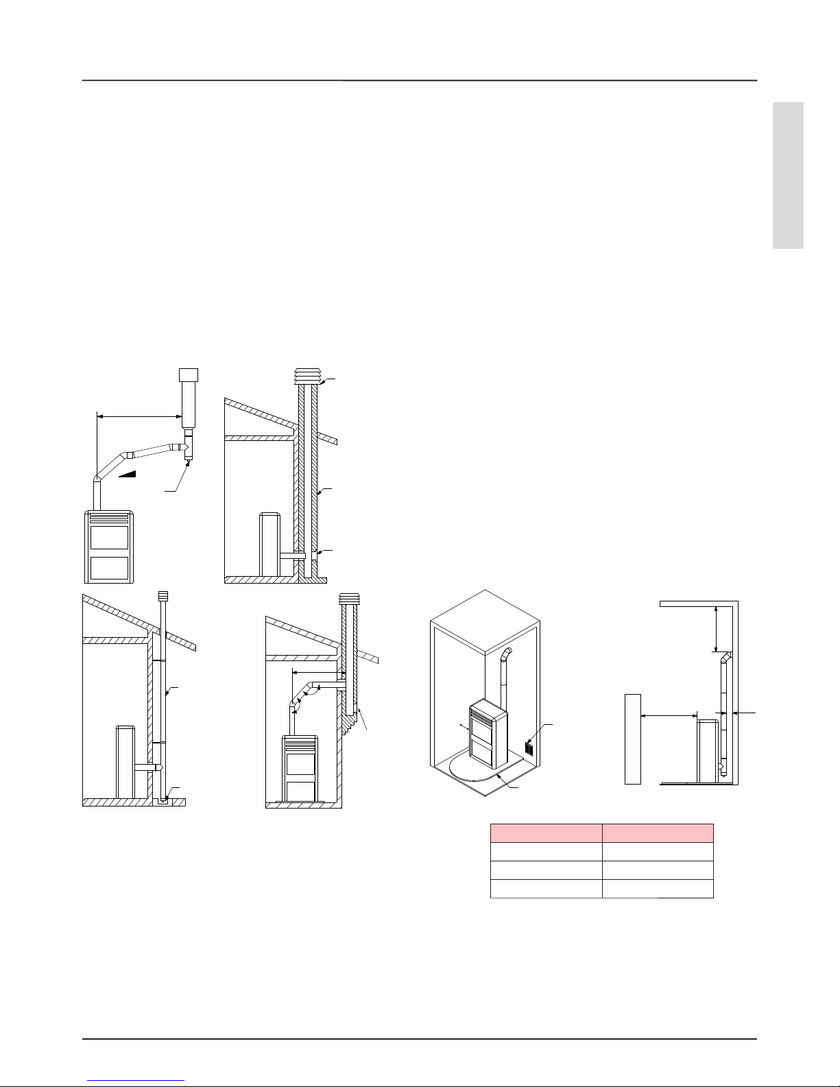
orizzontali. Per apparecchi dove si debbano raggiungere scarichi
a so tto o a parete non coassiali rispetto all’uscita dei fumi
dall’apparecchio, i cambiamenti di direzione dovranno essere
INSTALLAZIONE
realizzati con l’impiego di gomiti aperti non superiori a 45° (vedere
gure sotto).
ITALIANO
< 3 m
3 - 5 %
< 3 m
45°
45°
A
B
C
20 cm
INSTALLAZIONE
9
Comignolo
antivento
Canna
fumaria
Ispezione
È consigliato che il condotto fumario sia dotato di una camera
di raccolta di materiali solidi ed eventuali condense situata sotto
l’imbocco del canale da fumo, in modo da essere facilmente
apribile ed ispezionabile da sportello a tenuta d’ aria.
COLLEGAMENTO DELL’APPARECCCHIO ALLA CANNA
FUMARIA
La canna fumaria deve ricevere lo scarico da un solo generatore
di calore. E’ vietato lo scarico diretto verso spazi chiusi anche a
cielo libero.
EVACUAZIONE DEI PRODOTTI DELLA COMBUSTIONE
Lo scarico diretto dei prodotti della combustione deve essere
previsto a tetto e il condotto fumario deve avere le caratteristiche
previste nella sezione “Camino o canna fumaria singola”.
Condotto
esterno
isolato
Ispezione
Ispezione
Ispezione
COLLEGAMENTO A PRESE D’ARIA ESTERNE
L’apparecchio deve poter disporre dell’aria necessaria a garantirne
il regolare funzionamento mediante prese d’aria esterna. Le prese
d’aria devono rispondere ai seguenti requisiti:
1.avere una sezione libera totale di almeno 80 cm.
2.devono essere protette con griglia, rete metallica o idonea
protezione purché non riduca la sezione minima di cui al punto 1 e
posizionate in modo da evitare che possano essere ostruite.
Se l’aria di combustione viene prelevata direttamente dall’esterno
tramite un tubo, all’esterno è necessario montare una curva
verso il basso oppure una protezione contro il vento e non dovrà
essere posizionata alcuna griglia o simili. (si consiglia di e ettuare
RIFERIMENTI Distanza minima
A 500 mm
B 700 mm
C 500 mm
Minimo
80 cm
2
Salvapavimento
sempre la presa d’aria comunicante direttamente con l’ambiente
di installazione anche se l’aria viene prelevata dall’esterno tramite
tubo). L’a usso dell’aria può essere ottenuto anche da un locale
adiacente a quello di installazione purché tale usso possa avvenire
liberamente attraverso aperture permanenti comunicanti con
l’esterno. Il locale adiacente rispetto a quello di installazione non
deve essere messo in depressione rispetto all’ambiente esterno per
e etto del tiraggio contrario provocato dalla presenza in tale locale
di altro apparecchio di utilizzazione o di dispositivo di aspirazione.
Nel locale adiacente le aperture permanenti devono rispondere
ai requisiti sopra descritti. Il locale adiacente non può essere
adibito ad autorimessa, magazzino di materiale combustibile né
comunque ad attività con pericolo d’incendio.
RACCOMANDAZIONI DI SICUREZZA
I rivestimenti, indipendentemente dai materiali con cui sono
realizzati, devono costituire una costruzione autoportante rispetto
al blocco riscaldante e non essere a contatto con esso. La trave e le
niture in legno o di materiali combustibile devono essere poste al
di fuori della zona di irraggiamento del focolare o adeguatamente
isolati. Nel caso in cui nello spazio sovrastante il generatore
esistano coperture di materiale combustibile o sensibile al calore
deve essere interposto un diaframma di protezione in materiale
isolante e non combustibile. Elementi di materiale combustibile
o in ammabile quali arredi in legno, tendaggi ecc. direttamente
esposti all’irraggiamento del focolaio, devono essere posizionati
ad una distanza di sicurezza. L’installazione dell’apparecchio deve
garantire facile accesso per la pulizia dell’apparecchio stesso, dei
condotti dei gas di scarico e della canna fumaria.
REGOLAMENTAZIONI NAZIONALI, REGIONALI,
PROVINCIALI E COMUNALI
E’ necessario tenere in considerazione anche tutte le leggi e le
normative nazionali, regionali, provinciali e comunali presenti nel
paese in cui è stato installato l’apparecchio.
50 cm
< 5 m
> 5 m
< 5 m
50 cm
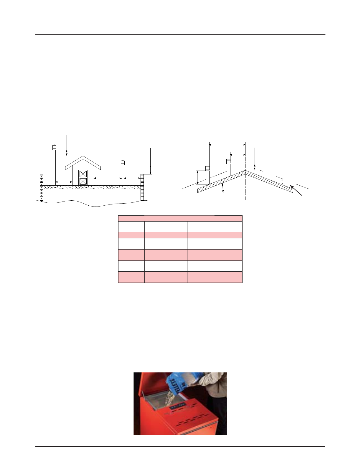
H min
β
IL PELLET
10
Il pellet utilizzato dovrà essere conforme alle caratteristiche descritte dalle norme:
Ö-Norm M 7135
DIN plus 51731
UNI CEN/TS 14961
AVVERTENZE: L’impiego di pellet scadente o di qualsiasi altro materiale, danneggia le funzioni del prodotto e può determinare la
cessazione della garanzia e l’annessa responsabilità del produttore. Per garantire una combustione senza problemi è necessario che
il pellet sia conservato in un luogo non umido. Consigliamo per i nostri prodotti di utilizzare pellet del diametro di 6 mm. Per il caricamento
del pellet vedi immagini sottostanti.
IL PELLET
COMIGNOLO
Il comignolo deve rispondere ai seguenti requisiti:
avere sezione interna equivalente a quella del camino;
avere sezione utile di uscita non inferiore al doppio di quella interna del camino;
essere costruito in modo da impedire la penetrazione nel camino della pioggia, della neve, di corpi estranei ed in modo che
anche in caso di venti di ogni direzione e inclinazione sia comunque assicurato lo scarico dei prodotti della combustione.
essere posizionato in modo da garantire un’adeguata dispersione e diluizione dei prodotti della combustione e comunque
al di fuori della zona di re usso in cui e’ favorita la formazione di contropressioni. Tale zona ha dimensioni e conformazioni
diverse in funzione dell’angolo di inclinazione della copertura, per cui risulta necessario adottare le altezze minime indicate
negli schemi di gura sottostante.
Il comignolo deve essere privo di mezzi meccanici di aspirazione.
Distanza > A
Distanza < A
50 cm oltre il colmo
ZONA DI REFLUSSO
altezza zona di
re usso
TETTO INCLINATO
TETTO PIANO
COMIGNOLI, DISTANZE E POSIZIONAMENTI
Inclinazione
del tetto
Distanza tra il colmo
e il camino
Altezza minima del camino
(misurata dallo sbocco)
β A (m) H (m)
15°
< 1,85 0,50 m oltre il colmo
> 1,85 1,00 m dal tetto
30°
< 1,50 0,50 m oltre il colmo
> 1,50 1,30 m dal tetto
45°
< 1,30 0,50 m oltre il colmo
> 1,30 2,00 m dal tetto
60°
< 1,20 0,50 m oltre il colmo
> 1,20 2,60 m dal tetto

ITALIANO
INSTALLAZIONE E DISPOSITIVI DI SICUREZZA IMPIANTO IDRAULICO
11
INSTALLAZIONE E DISPOSITIVI DI SICUREZZA IMPIANTO IDRAULICO
Durante l’installazione della caldaia è OBBLIGATORIO inserire
nell’impianto un manometro per la visualizzazione della
pressione dell’acqua. L’installazione, i relativi collegamenti
dell’impianto, la messa in servizio e la veri ca del corretto
funzionamento dovranno essere eseguiti a regola d’arte,
nel pieno rispetto delle normative vigenti, sia nazionali che
regionali e comunali, nonché delle presenti istruzioni.
Per l’Italia, l’installazione deve essere eseguita da personale
professionalmente autorizzato (DM 22 gennaio 2008 n^37).
L’azienda declina ogni responsabilità per danni a cose e/o
persone provocati dall’impianto.
SICUREZZE PER IMPIANTO A VASO CHIUSO
Secondo la norma UNI 10412-2 (2006) vigente in Italia,
gli impianti chiusi devono essere provvisti di: valvola di
sicurezza, termostato di comando del circolatore, termostato
di attivazione dell’allarme acustico, indicatore di temperatura,
indicatore di pressione, allarme acustico, interrutore termico
automatico di regolazione, interrutore termico automatico di
blocco (termostato di blocco), sistema di circolazione, sistema
di espansione, sistema di dissipazione di sicurezza incorporato
al generatore con valvola di scarico termico (autoazionata),
qualora l’apparecchiatura non sia provvista di un sistema di
autoregolazione della temperatura.
DISTANZE DEI DISPOSITIVI DI SICUREZZA SECONDO LA
NORMATIVA
Componente Distanza
Sensori di sicurezza della
temperatura
A bordo macchina o non
superiore a 30 cm
Dispositivi mancanti perchè
non di serie
Non superiore a un metro,
sul tubo di mandata
I sensori di sicurezza della temperatura devono essere a
bordo macchina o a una distanza non superiore a 30 cm dal
collegamento di mandata.
Qualora i generatori non siano provvisti di tutti i dispositivi,
quelli mancanti, possono essere installati sulla tubazione di
mandata del generatore, entro una distanza, dalla macchina,
non superiore a 1 m.
Gli apparecchi per riscaldamento di tipo domestico a
caricamento automatico devono: essere dotati di un termostato
di blocco del combustibile oppure essere dotati un circuito di
ra reddamento predisposto dal costruttore dell’apparecchio.
Il circuito di ra redamento deve essere attivato da una valvola
di sicurezza termica tale da garantire che non venga superata
la temperatura limite imposta dalla norma.
Il collegamento tra il gruppo di alimentazione e la valvola deve
essere privo di intercettazioni.
La pressione a monte del circuito di ra reddamento deve
essere di almeno 1,5 bar.
IMPIANTO IDRAULICO
In questo capitolo sono descritti alcuni concetti che fanno
riferimento alla normativa italiana UNI 10412-2 (2006). Come
descritto in precedenza, per l’installazione dovranno essere
rispettate tutte le eventuali normative nazionali, regionali,
provinciali e comunicali vigenti previste dal paese in cui è
stato installato l’apparecchio.
TIPOLOGIA DI IMPIANTO
Esistono 2 di erenti tipologie di impianto: impianto a vaso
aperto e impianto a vaso chiuso.Il prodotto è stato progettato e
realizzato per lavorare con impianti a vaso chiuso.
IMPIANTO A VASO CHIUSO PER APPARECCHIATURE A
CARICAMENTO AUTOMATICO
Impianto in cui l’acqua in esso contenuta non è in
comunicazione diretta o indiretta con l’atmosfera. In generale
l’impianto a vaso chiuso è dotato di uno dei seguenti dispositivi
di espansione:
Vaso d’espansione chiuso precaricato, con membrana
impermeabile al passaggio dei gas.
Sistema d’espansione chiuso automatico con
compressore e membrana impermeabile al passaggio dei
gas.
Sistema d’espansione chiuso automatico, con pompa di
trasferimento e membrana impermeabile al passaggio dei
gas.
Sistema di espansione senza diaframma.
CONTROLLI ALLA PRIMA ACCENSIONE
Prima di allacciare la caldaia prevedere:
a) un lavaggio accurato di tutte le tubazioni dell’impianto onde
rimuovere eventuali residui che potrebbero compromettere il
buon funzionamento di qualche componente dell’impianto
(pompe, valvole, ecc.).
b) un controllo per veri care che il camino abbia un tiraggio
adeguato, non presenti strozzature e che non siano inseriti
nella canna fumaria scarichi di altri apparecchi.
Solo dopo questo controllo può essere montato il raccordo
camino fra caldaia e canna fumaria.Si consiglia un controllo
dei raccordi con canne fumarie preesistenti.
CARATTERISTICHE DELL’ACQUA DI ALIMENTAZIONE
Le caratteristiche chimico- siche dell’acqua dell’impianto e di
reintegro sono fondamentali per il buon funzionamento e la
durata della caldaia.
Fra gli inconvenienti causati da cattive qualità dell’acqua
d’alimentazione il più frequente è l’incrostazione delle super ci
di scambio termico.
Meno frequente ma ugualmente grave è la corrosione delle
super ci lato acqua di tutto il circuito.
È noto che le incrostazioni calcaree a causa della loro bassa
conduttività termica riducono di molto lo scambio termico
anche in presenza di pochi millimetri, determinando
dannosissimi riscaldamenti localizzati. È decisamente
consigliabile e ettuare un trattamento dell’acqua nei seguenti
casi:
a) elevata durezza dell’acqua disponibile (superiore a 20°f)
A
B
C
D
E
1
2
3
INSTALLAZIONE E DISPOSITIVI DI SICUREZZA IMPIANTO IDRAULICO
12
b) impianti molto estesi
c) grandi quantità d’acqua reintegrata per perdite
d) riempimenti successivi dovuti a lavori di manutenzione
dell’impianto
Per il trattamento delle acque di alimentazione degli impianti
termici è consigliabile rivolgersi sempre a ditte specializzate.
RIEMPIMENTO IMPIANTO
Una volta e ettuati i collegamenti idraulici si può procedere al
collegamento dell’impianto.Aprire tutte le valvole di s ato aria
dei radiatori, della caldaia e dell’impianto.Aprire gradualmente
il rubinetto di carico accertandosi che le valvole di sfogo aria
funzionino regolarmente. Attraverso il manometro controllare
che l’impianto risulti in pressione. Nel caso di impianto a vaso
chiuso raggiungere la pressione di circa 0,11 – 0,12 MPa (1,1
– 1,2 bar). Per impianti a vaso aperto la pressione nella parte
più bassa della caldaia è data dall’altezza a cui è posto il vaso.
Chiudere il rubinetto di carico e quindi sfogare nuovamente
l’aria dalla caldaia attraverso la valvola di s ato.
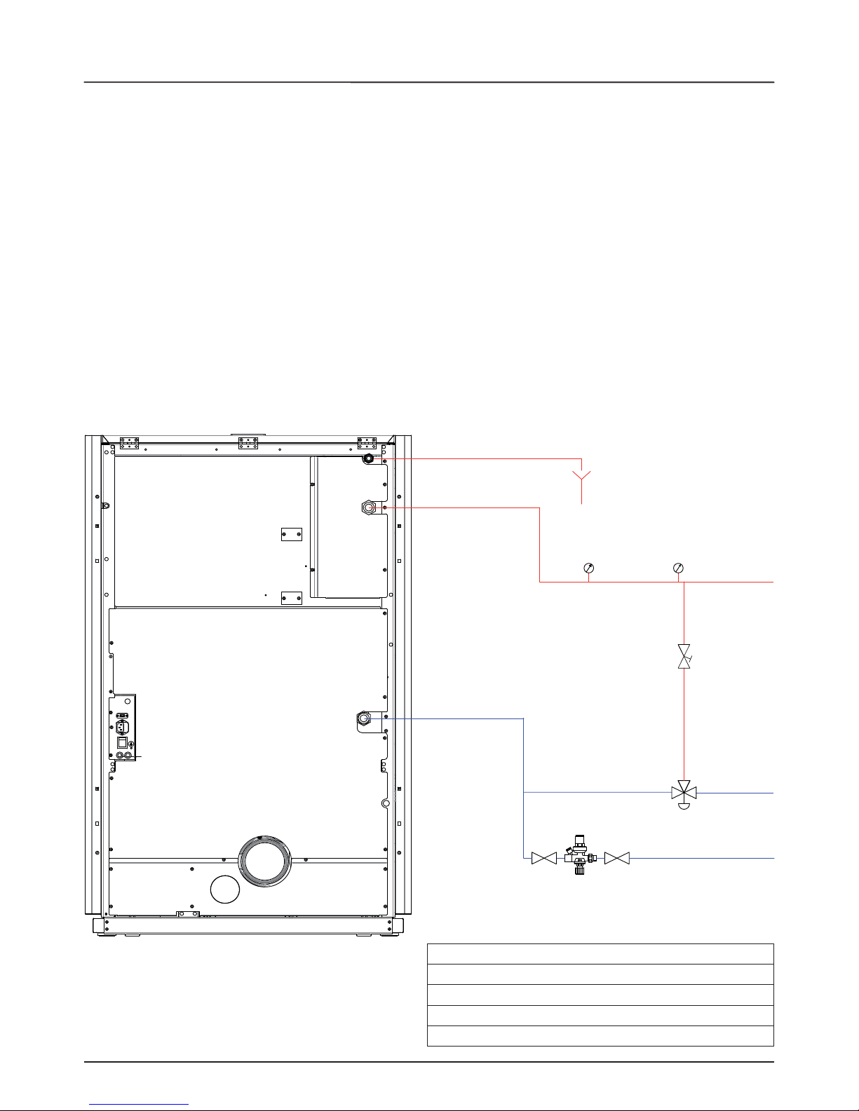
VALVOLA MISCELATRICE TERMOSTATICA
OBBLIGATORIA
La valvola miscelatrice termostatica automatica trova
applicazione nelle caldaie a combustibile solido in quanto
previene il ritorno di acqua fredda nello scambiatore. Le tratte
1 e 3 sono sempre aperte e, assieme alla pompa installata
sul ritorno, garantiscono la circolazione dell’acqua all’interno
dello scambiatore della caldaia a biomassa. Una elevata
temperatura di ritorno permette di migliorare l’e cienza,
riduce la formazione di condensa dei fumi e allunga la vita della
caldaia. Le valvole in commercio presentano svariate tarature,
Extra ame consiglia l’utilizzo del modello 55°C con connessioni
idrauliche da 1’’. Una volta raggiunta la temperatura di taratura
della valvola, viene aperta la tratta 2 e l’acqua della caldaia va
all’impianto attraverso la mandata. Extra ame consiglia di non
utilizzare questo dispositivo qualora l’acqua calda sanitaria
venga prodotta mediante uno scambiatore istantaneo.
valvola
miscelatrice
termostatica
automatica
55°C
Scarico valvola
di sicurezza
Termometro
Manometro
Ritorno
Mandata
Mandata
A = aria primaria Ø 60 mm
B = condotto espulsione fumi Ø 120 mm
C = mandata / uscita caldaia 1 “
D = ritorno / ingresso caldaia 1 “
E = scarico sicurezza 3 bar 1/2”
valvola
bilanciamento
gruppo caricamento impianto
ITALIANO
85°C
4
29 / 04 /2010
18 : 56
STBY
SABATO
-
+
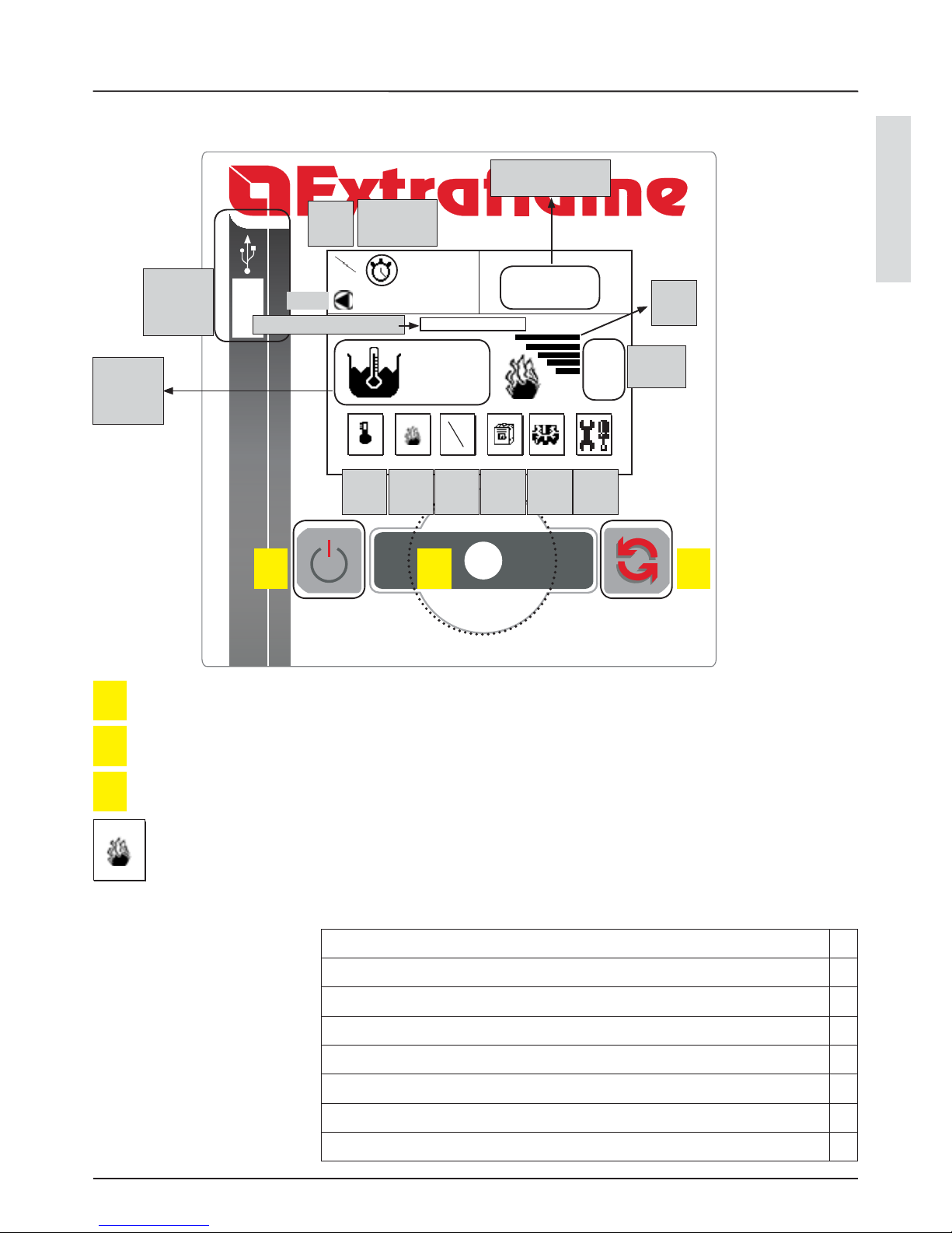
DISPLAY: QUADRO COMANDI
13
DISPLAY: QUADRO COMANDI
set
temper.
Entrata
USB
modalità auto/
man
stby
pompa
Potenza
impostata
T° acqua
*L’icona della amma non è presente negli stati OFF, START, PUL BRACIERE, PUL - FINALE, ALLARME, ATTESA
RIPARTENZA
*Lampeggia in ACCENSIONE
*Fissa in AVVIO e LAVORO. Durante la fase di LAVORO visualizza ssa la amma con la potenza reale di lavoro
P1 P2 P3
Tasto di accensione o spegnimento caldaia
P1
Encoder (rotellina), girando seleziono le diverse icone a display, premendolo entro nella selezione
P2
Tasto con molteplici funzioni (avanzamento nei menù ecc)
P3
*
LAVORO
visualizzazione dello stato
Gestione Accumulo sanitario *
Gestione Pu er *
3 zone riscaldamento *
Opzione acqua sanitaria istantanea *
Gestione pompa pu er o 4^ zona riscaldamento *
Gestione antilegionella per accumulo sanitario *
Gestione crono accumulo sanitario *
Gestione e controllo uscita ausiliaria *
Extra ame dispone di una scheda
optional supplementare che
permette alla caldaia le seguenti
ulteriori funzioni nella gestione
dell’impianto.
set
potenza
regolaz.
utente
stato
set
utente
set
installat.
giorno, data e ora
Potenza
reale
FUNZIONAMENTO
14
FUNZIONAMENTO
Le fasi che la caldaia esegue sono: START, PULIZIA BRACIERE, ACCENSIONE, AVVIAMENTO e FUNZIONAMENTO.
Durante la PULIZIA BRACIERE avvengono alcuni colpi botola, ossia una pulizia automatica del braciere per permettere un
funzionamento ottimale. Durante la fase di ACCENSIONE il pellet caricato entra in combustione, grazie al calore immesso nel
braciere da parte della resistenza elettrica. Avvenuta la fase di accensione la caldaia passa in AVVIAMENTO, fase di preparazione
al lavoro. Nella fase di “FUNZIONAMENTO” l’utente può impostare la potenza e la temperatura dell’acqua desiderata. Maggiore
è la potenza, maggiore sarà la velocità del prodotto stesso nel mandare a regime l’impianto.
ACCENSIONE
Premere il tasto P1 per 3 secondi. Durante le prime accensioni è possibile che vengano prodotti dei leggeri odori dovuti
all’essicazione delle vernici e dei siliconi utilizzati. Evitare una permanenza prolungata e areare il locale. Dopo un check-up
iniziale, la macchina inizierà con una pulizia del braciere, e ettuando alcuni colpi botola, per poi passare alla fase di ACCENSIONE,
seguendo questi 3 punti:
1.Alimentazione della candeletta
2.Alimentazione del motore di carico pellet
3.Partenza del motore fumi.
Se la macchina non si è accesa, si veri cherà l’allarme di MANCATA ACCENSIONE.
In caso di allarme per mancata accensione:
attendere il ra reddamento della macchina (schermo verde)
premere il tasto P1 per 3 secondi
LAVORO
La caldaia lavorerà per raggiungere la temperatura acqua impostata dall’utente. Il circolatore entrerà in funzionamento non appena
saranno raggiunti i parametri impostati di fabbrica. Si consiglia una zona di riscaldamento sempre aperta per rendere più omogeneo
il funzionamento del prodotto ed evitare blocchi per sovratemperatura. La caldaia modulerà automaticamente all’avvicinarsi della
temperatura impostata, portandosi al minimo della potenza, per andare poi in spegnimento (H o ) se supererà il set impostato
oltre i parametri di fabbrica. Quando l’acqua scenderà di temperatura la caldaia ripartirà.
Nota bene: le tempistiche generali dei vari stati di funzionamento sono variabili in base alla tipologia d’ impianto e in
base ai parametri impostati.
SPEGNIMENTO
Lo spegnimento può avvenire in modo manuale premendo il tasto P1 per tre secondi, in modo automatico (per un comando
programmato dall’utenza nella modalità automatica), per un contatto di un termostato supplementare esterno soddisfatto o
per H OFF, ossia temperatura dell’acqua raggiunta e superata.
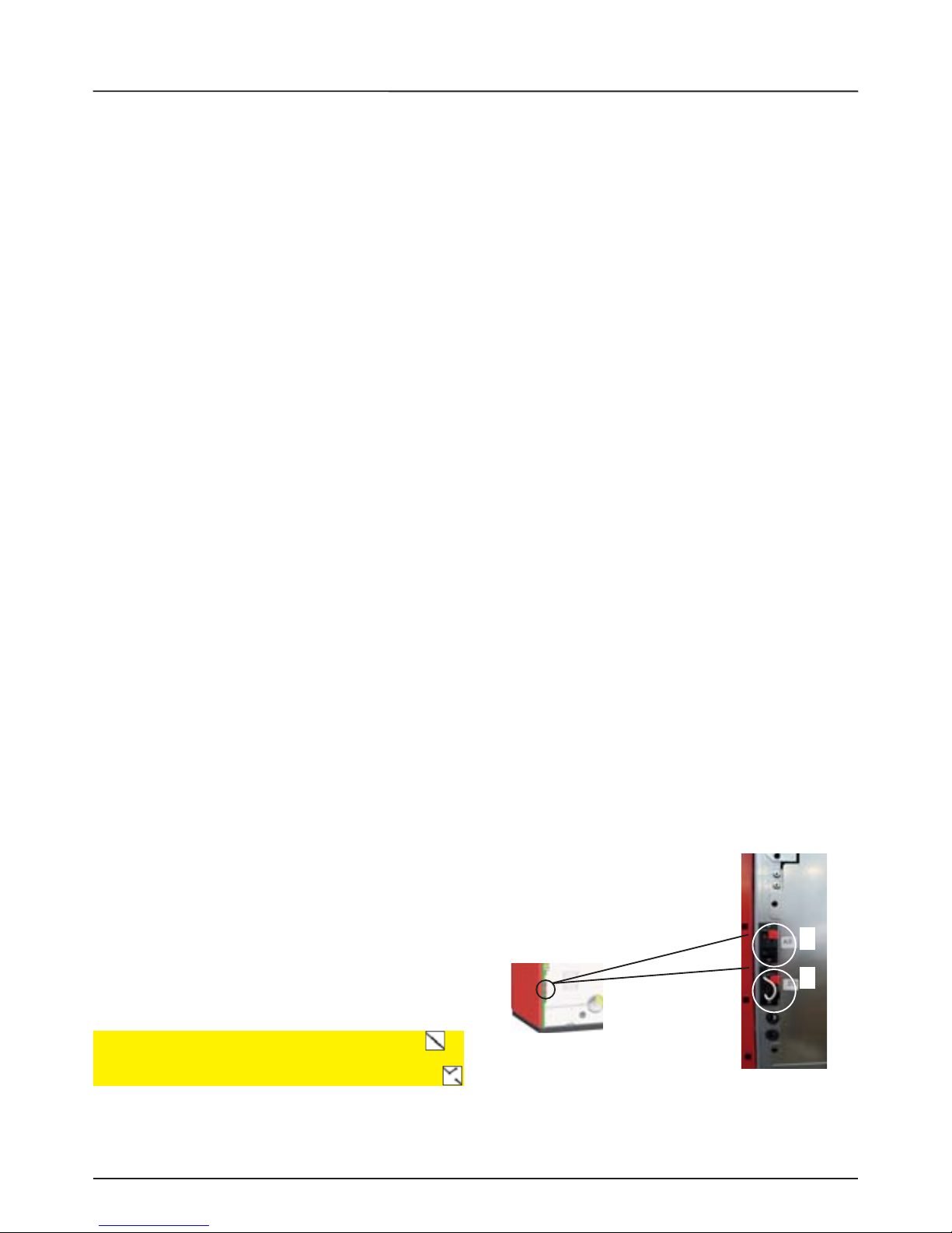
TERMOSTATO SUPPLEMENTARE STBY
Il prodotto può funzionare anche con termostato supplementare.
Lo stato del contatto sarà visualizzato a display. Il termostato, se
soddisfatto manda la caldaia in spegnimento, visualizzando STAND
BY nel display.
Appena il termostato tornerà in richiesta la caldaia si riaccenderà
(sempre che non sia presente uno stato di H OFF, ossia uno
spegnimento obbligato per la temperatura acqua caldaia oltre il
limite imposto dall’utente e dai parametri di fabbrica). In caso di H
OFF, appena l’acqua sarà scesa sotto i livelli impostati di fabbrica si
riavrà l’accensione.
Sono presenti 2 morsetti casse nel retro. Il morsetto casse ponticellato di fabbrica e segnalato con STBY (numero di riferimento
2) è quello per il termostato supplementare. Il morsetto con la scritta AUX (numero riferimento 1) serve per connettere l’optional scheda supplementare).
Raccomandazioni: posizionare il termostato esterno in un punto lontano da fonti di calore, ad un altezza di circa 1.5 m.
1
2
Contatto chiuso (in richiesta) = accensione automatica
Contatto aperto (soddisfatto) = spegnimento automatico
ITALIANO
-
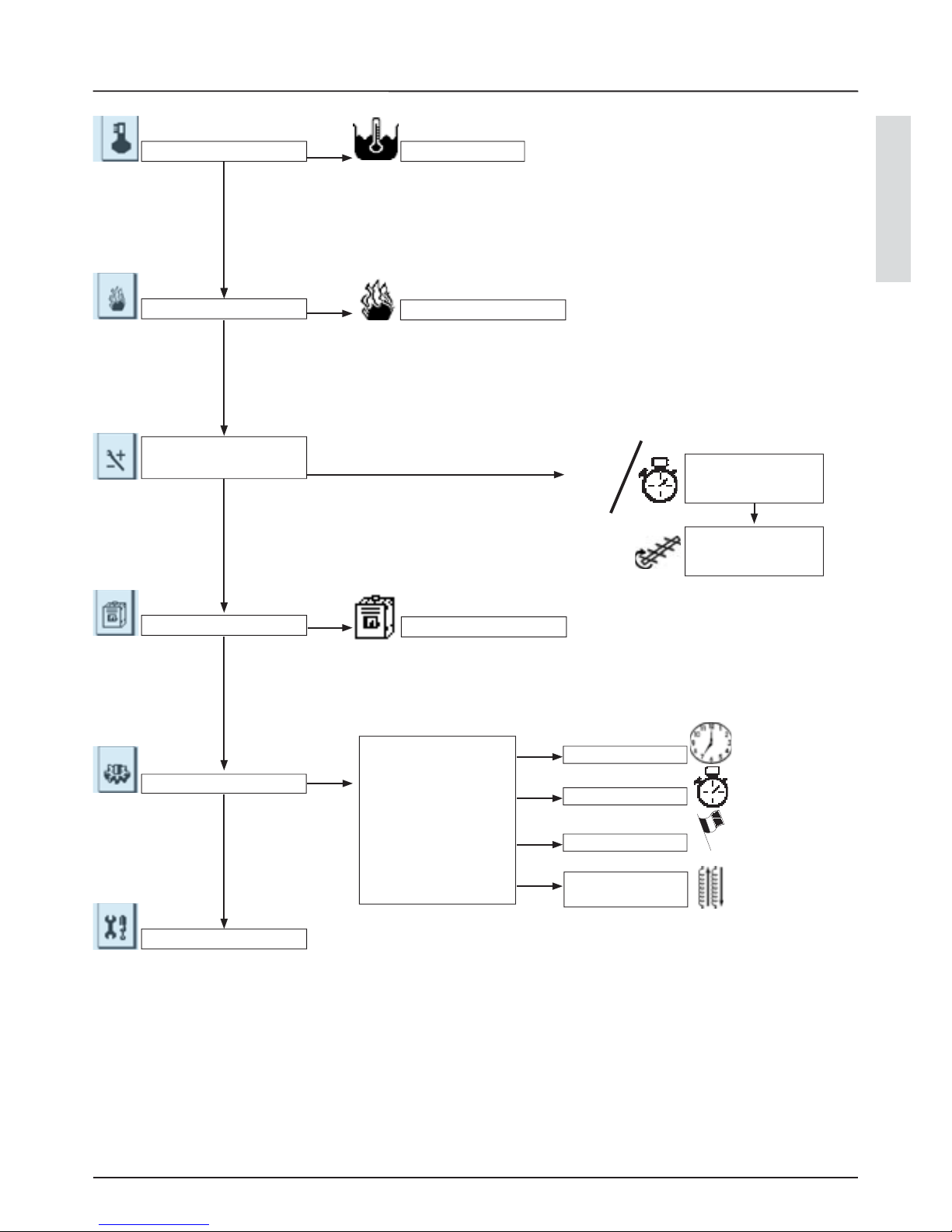
MENÙ
15
TEMPERATURA
SET POTENZA
REGOLAZIONE
UTENTE
STATO
SET UTENTE
SET OROLOGIO
SET CRONO
LINGUA
SET SCAMBIATORE
SET OROLOGIO
MENÙ
INSTALLATORE*
MANUALE/
AUTOMATICO
REGOLAZIONE
PELLET
SET H2O
STATO STUFA
SET CRONO
LINGUA
SET
SCAMBIATORE
* SET INSTALLATORE: il presente menù è riservato all’assistenza
SET POTENZA
85
SET H20
c
°
P1 P2 P3
05
MENÙ
16
Dalla schermata principale ruotare P2 per selezionare
l’icona
Premere P2 per confermare
Ruotare P2 per regolare la temperatura
Confermare e memorizzare premendo P2
Per uscire senza memorizzare premere il tasto P1
REGOLAZIONE TEMPERATURA
SET POTENZA
P1 P2 P3
Dalla schermata principale ruotare P2 per selezionare
l’icona
Premere P2 per confermare
Ruotare P2 per regolare la potenza
Confermare e memorizzare premendo P2
Per uscire senza memorizzare premere il tasto P1
REGOLAZIONE POTENZA

ITALIANO
-
-
MENÙ
17
Il menù set utente o re le seguenti possibilità
modalità automatica/manuale: consente l’abilitazione/disabilitazione del crono interno alla caldaia
regolazione pellet: consente la regolazione del pellet
La modalità automatica permette l’accensione e lo spegnimento della caldaia in modo automatico, seguendo una
programmazione impostata dall’utente. Per la regolazione delle fascie orarie vedi il paragrafo REGOLAZIONE CRONO
Dalla schermata principale ruotare P2 per selezionare l’icona
Premere P2 per confermare
Ruotare P2 per portare in ON l’abilitazione del crono
Confermare e memorizzare premendo P2
per uscire senza memorizzare premere il tasto P1
OFF
ABILITA CRONO
ON
ABILITA CRONO
P1 P2 P3 P1 P2 P3
P1 P2 P3
Dalla schermata principale ruotare P2 per selezionare
l’icona
Premere P2 per confermare e successivamente premere
ancora P2 per scegliere REGOLAZIONE PELLET
Ruotare P2 per modi care il parametro in percentuale
(-20/+20)
Confermare e memorizzare premendo P2
per uscire senza memorizzare premere il tasto P1
-20%
REGOLAZIONE PELLET
La caldaia permette la regolazione del pellet tramite il menù relativo. Considerando le tipologie diverse di pellet nel mercato,
l’utente può aumentare o diminuire la quantità di pellet in percentuale.
MENÙ REGOLAZIONI UTENTE
REGOLAZIONE PELLET
MODALITÀ AUTOMATICA/MANUALE
MENÙ
18
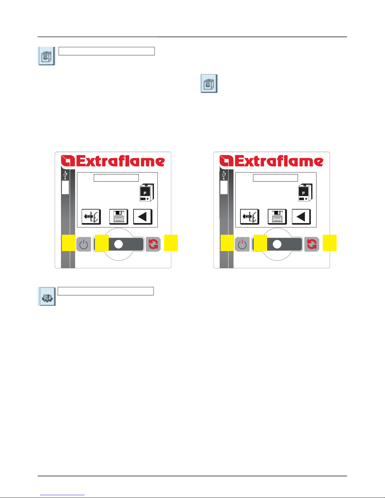
MOTORE...
OUT 2...
MOTORE PEL...
CANDELETTA...
Il menù set utente o re le seguenti possibilità:
set orologio: consente la regolazione dell’ aria e della data
set crono: permette la programmazione di 4 fascie orarie di funzionamento della caldaia, con accensioni e spegnimenti
automatici e impostazione della temperatura acqua desiderata per ogni fascia oraria
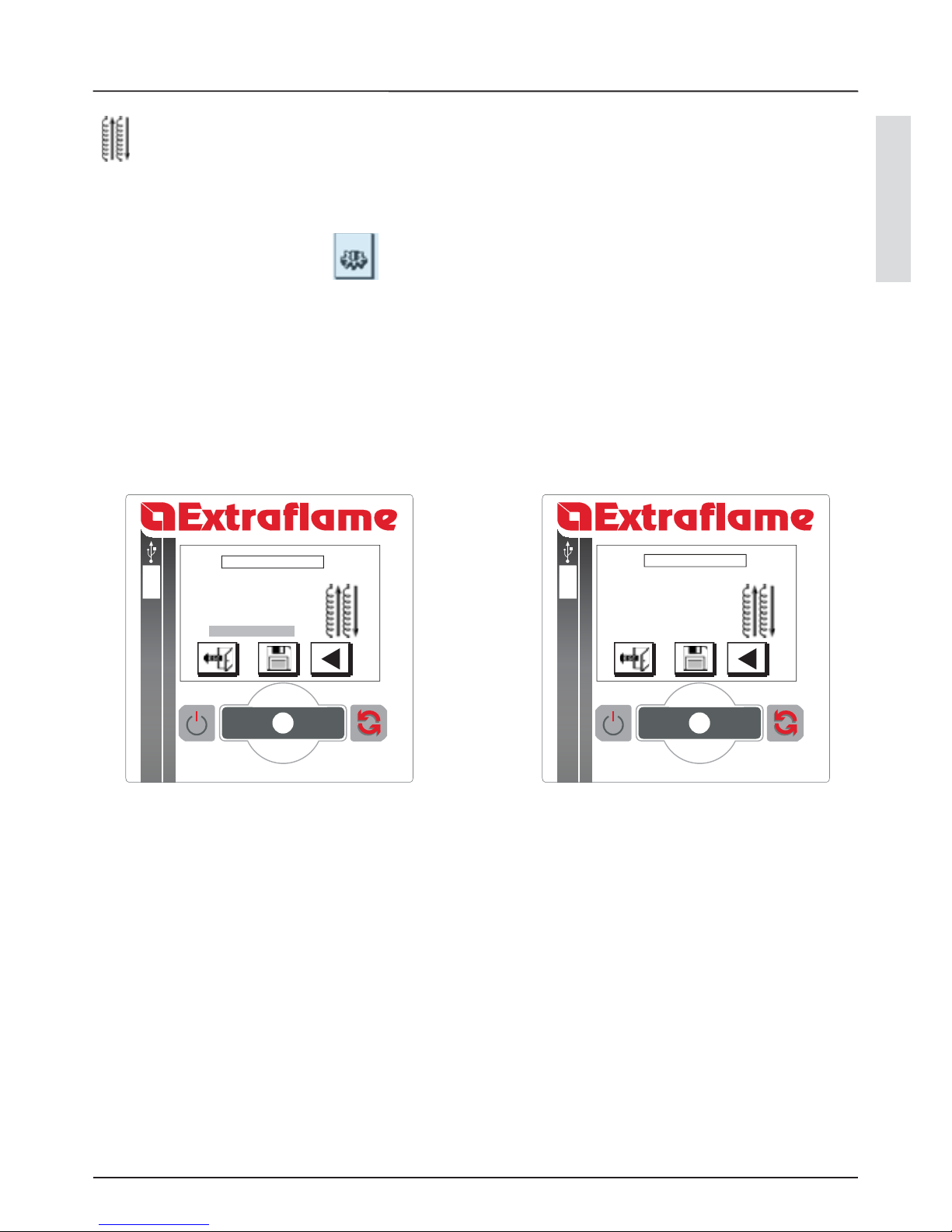
lingua: impostazione della lingua desiderata (italiano, inglese, francese, tedesco, spagnolo)
set scambiatore: programmazione degli orari di inizio e ne della pulizia automaticadegli scambiatori di calore.
MENÙ STATO
Il menù stato serve per visualizzare lo stato degli ingressi e delle uscite in scheda
Dalla schermata principale ruotare P2 per selezionare l’icona
Premere P2 per confermare (visualizzazione della schermata STATO 1)
Premere nuovamente P2 per visualizzare la schermata STATO 2
Per tornare indietro premere P3
Per uscire premere il tasto P1
P1 P2 P3
STATO 1 LP30
GIRI..
T FUMI..
T H2O..
P1 P2 P3
STATO 2 LP30
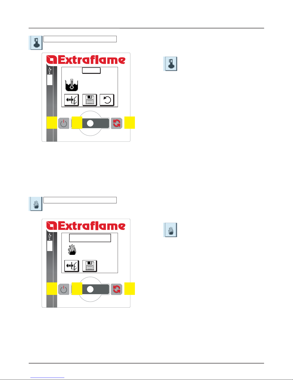
SET UTENTE
ITALIANO
MENÙ
19
MENU UTENTE
SET OROLOGIO
SET CRONO
LINGUA
SET SCAMBIATORE
SET OROLOGIO
GIORNO
ORE
MINUTI
DATA
MESE
ANNO
SABATO
23
21
04
06
10
Dalla schermata principale ruotare P2 per selezionare l’icona
Premere P2 per confermare
Ruotare P2 per selezionare “ SET OROLOGIO”
Confermare premendo P2
Ruotare P2 per selezionare il parametro desiderato
Premere P2 per entrare in modi ca
Ruotare P2 per modi care il valore
Premere P2 per confermare e uscire
Nel caso si voglia uscire senza memorizzare premere il tasto P1
P1 P2 P3
P1 P2 P3
SET OROLOGIO
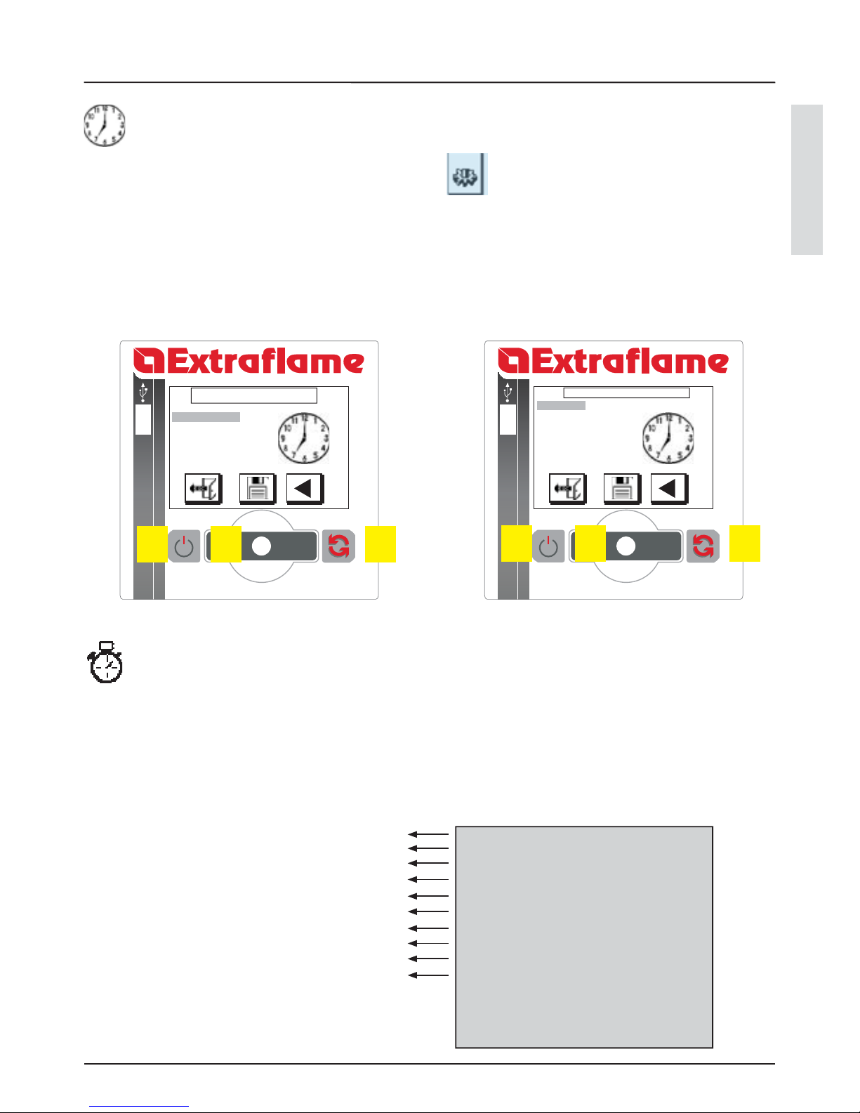
REGOLAZIONE CRONO
Tramite la regolazione del crono, ossia della modalità automatica, la caldaia può accendersi e spegnersi in modo automatico.
Il crono ha la priorità assoluta su ogni comando, per cui occore considerare questo fattore. E’ possibile programmare 4 fasce
orarie. Per default tutte le fascie sono in OFF
START PRG1
STOP PRG1
LUNEDI PRG1
MARTEDI PRG1
MERCOLEDI PRG1
GIOVEDI PRG1
VENERDI PRG1
SABATO PRG1
DOMENICA PRG1
SET PRG1
00:00
00:00
ON
OFF
OFF
OFF
OFF
OFF
OFF
...
Orario accensione prima fascia oraria
Orario spegnimento prima fascia oraria
giorno consentito o no (on - o )
giorno consentito o no (on - o )
giorno consentito o no (on - o )
giorno consentito o no (on - o )
giorno consentito o no (on - o )
giorno consentito o no (on - o )
giorno consentito o no (on - o )
impostazione della t° acqua
SPIEGAZIONE
SCHERMATA
P1 P2 P3 P1 P2 P3
MENÙ
20
Ruotare P2 per selezionare l’icona
Premere P2 per confermare
Ruotare P2 per selezionare “ SET CRONO”
Confermare premendo P2
Ruotare P2 per selezionare il parametro desiderato
Premere P2 per entrare in modi ca
Ruotare P2 per modi care il valore
Premere P2 per confermare e uscire
Nel caso si voglia uscire senza memorizzare premere il tasto P1
SET OROLOGIO
SET CRONO
LINGUA
SET SCAMBIATORE
MENU UTENTE
LINGUA
ITALIANO
MENÙ SET LINGUA
La caldaia permette l’impostazione delle seguenti lingue: italiano, inglese, francese, tedesco e spagnolo. Di default l’impostazione
è ITALIANO
Ruotare P2 per selezionare l’icona
Premere P2 per confermare
Ruotare P2 per selezionare “ LINGUA”
Confermare premendo P2
Ruotare P2 per selezionare il parametro desiderato
Premere P2 per entrare in modi ca
Ruotare P2 per modi care il valore
Premere P2 per confermare e uscire
Nel caso si voglia uscire senza memorizzare premere il tasto P1
P1 P2 P3 P1 P2 P3
SET OROLOGIO
SET CRONO
LINGUA
SCAMBIATORE
START PRG1
STOP PRG1
LUNEDI PRG1
...
SET UTENTE
SET CRONO
ITALIANO
MENÙ
21
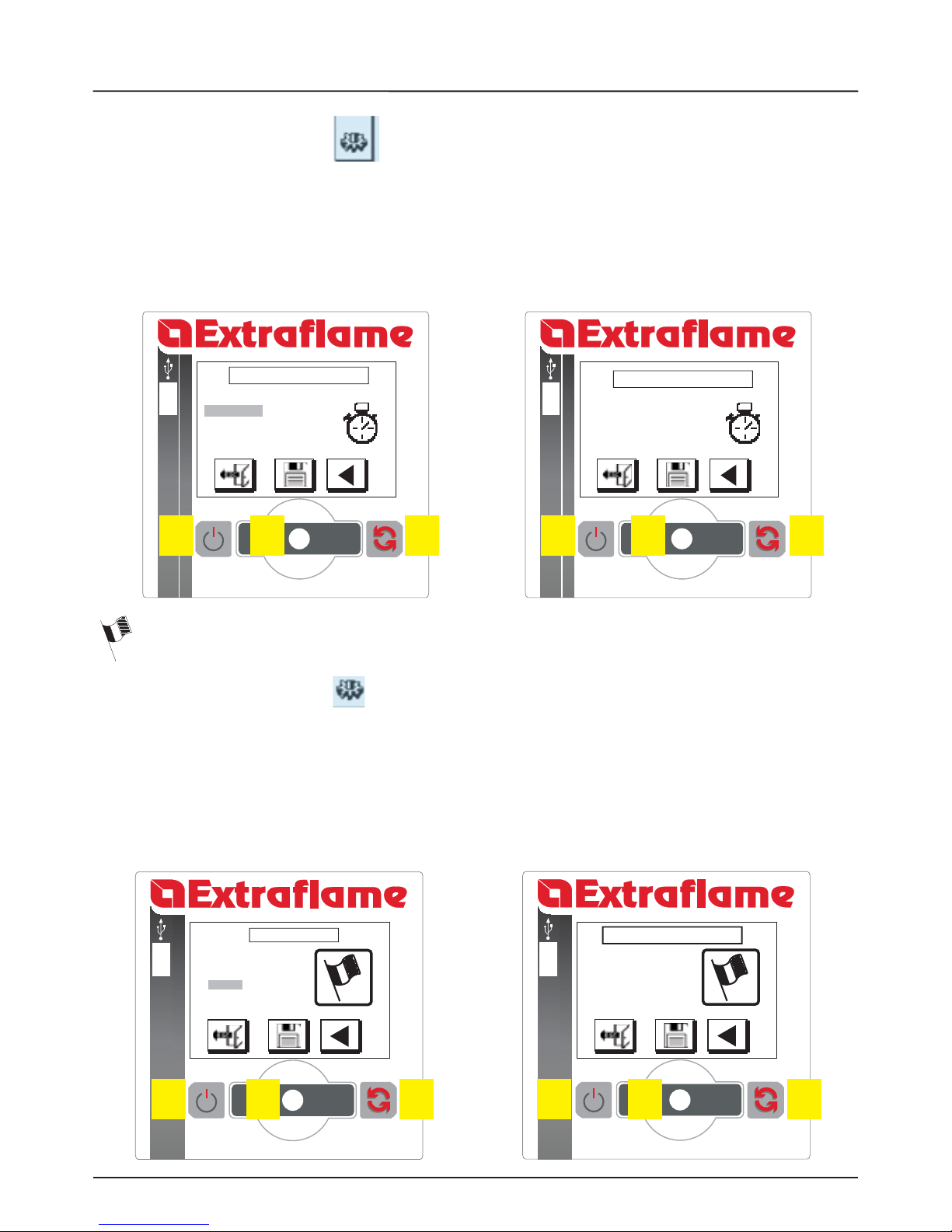
MENÙ SET SCAMBIATORE
SET OROLOGIO
SET CRONO
LINGUA
SET SCAMBIATORE
MENU UTENTE
Questo menù permette di programmare l’orario di inizio e ne della pulizia automatica dello scambiatore. La pulizia avviene in
modo meccanico attraverso delle molle metalliche che puliscono i condotti di scambio. Di default i parametri sono START 6:00
STOP 22:00 che signi ca che la pulizia è esclusa dalle 22 alle 6 del mattino.
START .. 00:00
STOP .. 00:00
Ruotare P2 per selezionare l’icona
Premere P2 per confermare
Ruotare P2 per selezionare “ SET SCAMBIATORE”
Confermare premendo P2
Ruotare P2 per selezionare il parametro desiderato
Premere P2 per entrare in modi ca
Ruotare P2 per modi care il valore
Premere P2 per confermare e uscire
Nel caso si voglia uscire senza memorizzare premere il tasto P1
SET SCAMBIATORE
29 / 04 /2010
18 : 56
-
STBY
SABATO
-
+
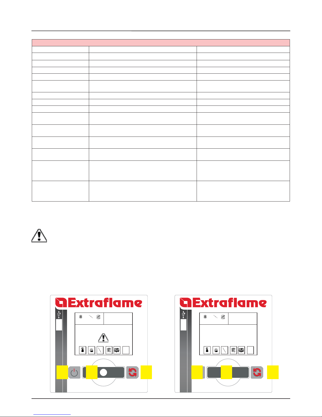
ALLARME ATTIVO
29 / 04 /2010
18 : 56
-
STBY
SABATO
-
+
MEMORIA ALLARME
“TIPO DI ALLARME”
P1 P2 P3
TABELLA SEGNALAZIONI
22
SEGNALAZIONI
Display Signi cato Spiegazione
START è in corso la fase di start -
CARICA PELLET è in corso il carico continuo del pellet durante l’accensione -
ACCENSIONE La caldaia si trova in fase di accensione -
AVVIO è in corso la fase di preparazione al lavoro -
LAVORO
è in corso la fase di lavoro normale, la caldaia sta lavorando
alla potenza impostata
-
PULIZIA BRACIERE è in corso la pulizia del braciere -
PUL FINALE è in corso la pulizia nale -
MODULA la caldaia sta funzionando alla potenza minima -
STANDBY
caldaia in attesa di riaccendersi a causa del termostato
esterno
la caldaia ripartirà quando il termostato esterno lo
richiederà
ATTESA RAFF BLACK OUT
la caldaia si sta ra reddando dopo una mancanza di
corrente.
concluso il ra reddamento si riaccenderà in modo
automatico
HOFF
Caldaia in attesa di riaccendersi perchè la temperatura in
dell’acqua ha superato i parametri impostati
appena la temperatura dell’acqua si abbasserà sotto
i parametri prestabiliti, la caldaia si riaccenderà
ANTIGELO
è in corso il funzionamento antigelo in quanto la t° H2O è
sotto la soglia impostata di fabbrica
il circolatore si attiva sino a che l’acqua ha raggiunto
il parametro preimpostato di fabbrica
ANTIBLOCCO
Se la caldaia è rimasta in stato di O per almento 96 ore,
il circolatore inizia a funzionare, in modo da evitare il
bloccaggio dello stesso.
il circolatore si attiva per un breve periodo, in modo
da evitare il blocco dello stesso
BLOCCO SCAM indica il blocco della pulizia dello scambiatore contattare centro di assistenza
TABELLA SEGNALAZIONI
ALLARME
Quando la caldaia va in allarme lo schermo diventa rosso e non accetta comandi esterni a display. Quando lo schermo diventa
verde, verrà visualizzato “MEMORIA ALLARMI” con la tipologia di allarme e la caldaia potrà rispondere ai comandi esterni.
Se l’allarme è risolvibile dall’utente, una volta risolto si può riaccendere la caldaia premendo il tasto P1. In caso di un allarme più
complesso, contattare l’assistenza.
P1 P2 P3
ITALIANO
TABELLA ALLARMI
23
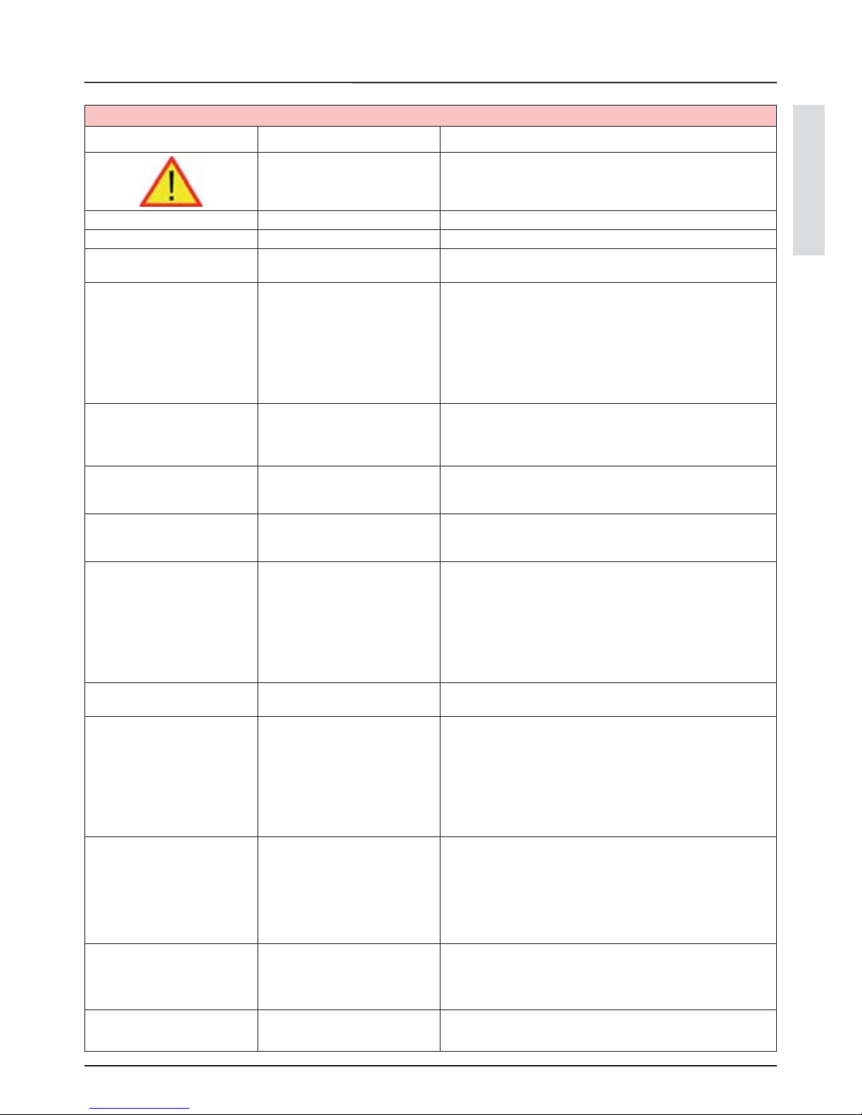
ALLARMI
Display Motivazione Risoluzione
Indica la presenza di un allarme.
Per resettare l’allarme è sufficiente tenere premuto “accensione/
spegnimento” per 3 secondi quando la caldaia è fredda.
ASPIRATGUASTO Guasto motore fumi contattare centro assistenza
SONDA FUMI Guasto sonda fumi. contattare centro assistenza
HOT FUMI Temperatura fumi elevata
verificare la taratura della regolazione pellet, nel caso non si risolvi
contattare tecnico autorizzato
ALL NO FLUSSO
La porta non è chiusa
correttamente.
Il cassetto cenere non è chiuso
correttamente.
La camera di combustione è
sporca.
Il condotto di espulsione dei fumi o
di adduzione aria è ostruito.
Verificare la chiusura ermetica della porta.
Verificare la chiusura ermetica del cassetto cenere.
Verificare la pulizia sia del condotto fumi che della camera di
combustione.
Verificare la pulizia del condotto di adduzione dell’aria e del sensore
di flusso
MANCATA ACCENSIONE
Il serbatoio del pellet è vuoto.
Taratura carico pellet inadeguata.
Verificare la presenza o meno di pellet all’interno del serbatoio.
Regolare l’afflusso di pellet
Verificare le procedure descritte al capitolo “Accensione”.
NO ACC BLACK OUT
Mancanza di corrente durante la
fase di accensione.
Portare la caldaia in OFF tramite il tasto 1 e ripetere le procedure
descritte al capitolo “Accensione”.
MANCANO PELLET
Il serbatoio del pellet è vuoto.
Carenza di carico di pellet.
Il motoriduttore non carica pellet.
Verificare la presenza o meno di pellet all’interno del serbatoio.
Regolare l’afflusso di pellet(vedi “Regolazione carico pellet”).
ALLARME DEPR
La porta non è chiusa
correttamente.
Il cassetto cenere non è chiuso
correttamente.
La camera di combustione è
sporca.
Il condotto di espulsione dei fumi
è ostruito
Verificare la chiusura ermetica della porta.
Verificare la chiusura ermetica del cassetto cenere.
Verificare la pulizia sia del condotto fumi che della camera di
combustione.
Verificare il pressostato meccanico (lato aria)
DEBIMETRO GUASTO
sensore di flusso difettoso
sensore scollegato
contattare centro assistenza
SOVRATEMP H20
l’acqua all’interno della caldaia ha
superato i 95°C.
Possibile aria nell’impianto.
Mancanza di circolazione
adeguate.
Mancanza della zona di sicurezza o
non adeguata.
Possibile anomalia del circolatore.
contattare centro assistenza
ALLARME PRESSIONE
MINIMA
la pressione impianto letta dal
pressostato è troppo bassa.
Possibile presenza di aria
nell’impianto.
Possibile carenza di acqua o perdite
dovute ad anomalie in qualche
componente dell’impianto.
contattare centro assistenza
BLOCCO BOTOLA
La pulizia automatica del braciere
risulta bloccata.
Spegnere la macchina, attendere il completo raffreddamento e
ripetere il ciclo di accensione.
Se il problema persiste, le operazioni di ripristino dovranno essere
effettuate da parte di un tecnico autorizzato.
SONDA ACQUA Guasto sonda H2O contattare centro assistenza
TABELLA ALLARMI
PULIZIA CALDAIA
24
PULIZIA CALDAIA
Le operazioni di manutenzione garantiscono un corretto funzionamento del prodotto nel tempo. L’inadempienza di queste
operazioni può pregiudicare la sicurezza del prodotto.
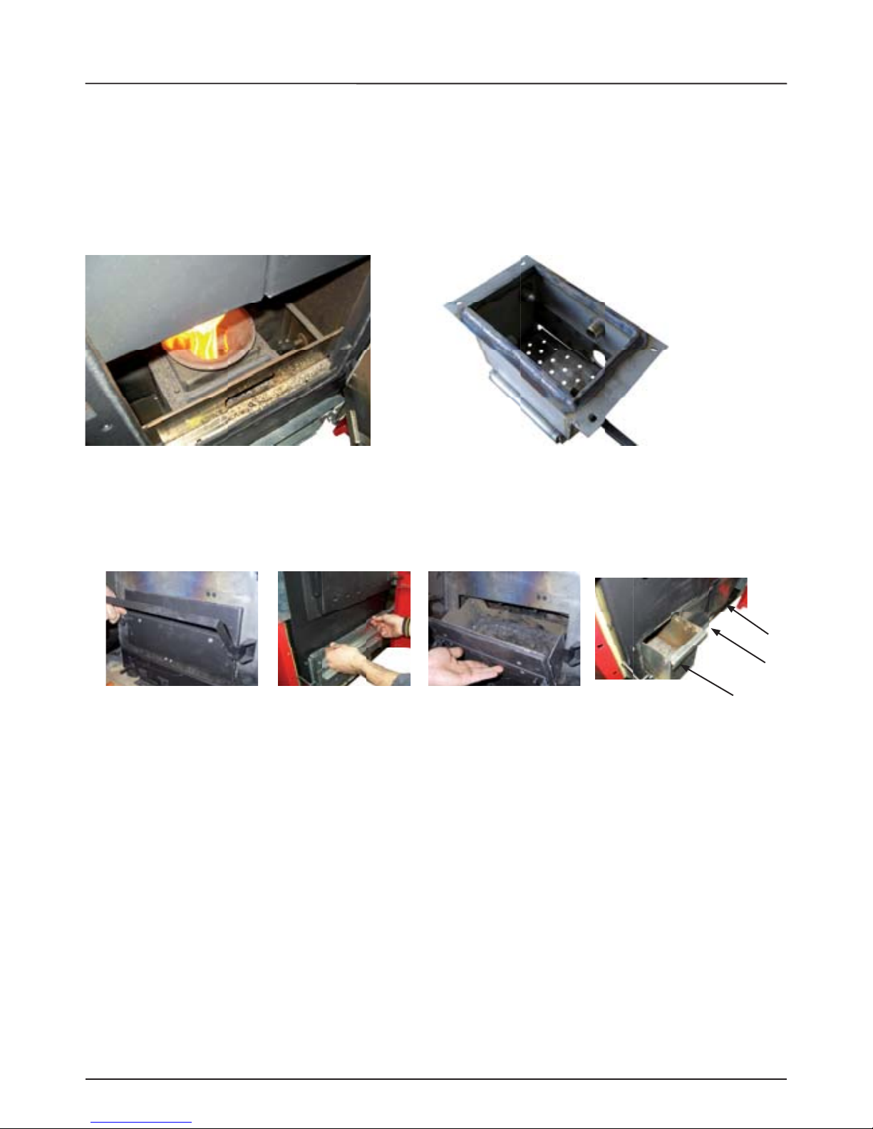
PULIZIA BRACIERE
Tramite un sistema meccanico la pulizia del braciere viene eseguita ad intervalli pre ssati in modo automatico dalla caldaia.
Nella gura sotto si può notare il braciere con l’apertura sottostante.
L’azienda consiglia comunque di asportare tramite un aspirapolvere speci co eventuali residui di cenere almeno 1 volta ogni 2
giorni, o comunque in base all’utilizzo stesso del prodotto.
* L’immagine potrebbe diversi carsi leggermente dal prodotto originale.
CASSETTO CENERE LP30
Da macchina spenta, aprire il cassetto cenere per svuotarne il contenuto. La frequenza di svuotamenti del cassetto cenere, sarà
proporzionale all’utilizzo del prodotto. In Lp30 sono presenti 3 cassetti.
GUARNIZIONI PORTA E CASSETTO CENERE
Le guarnizioni garantiscono l’ermeticità della caldaia e il conseguente buon funzionamento della stessa.
E’ necessario che esse vengano periodicamente controllate: nel caso risultassero usurate o danneggiate è necessario sostituirle
immediatamente.
Queste operazioni dovranno essere eseguite da parte di un tecnico autorizzato.
N.B. Per un corretto funzionamento, la caldaia deve subire una manutenzione ordinaria da parte di un tecnico autorizzato,
almeno una volta all’anno
Se il cavo di alimentazione è danneggiato, deve essere sostituito dal servizio di assistenza tecnica o comunque da una persona
con quali ca similare, in modo da prevenire ogni rischio.
PULIZIA DEL CAMINO
Annualmente, ossia ogni volta che se ne presenti la necessità, aspirare e pulire il condotto che porta al camino. Se esistono dei
tratti orizzontali è necessario asportare i residui, prima che questi ostruiscano il passaggio dei fumi. La NON PULIZIA pregiudica
la sicurezza.

ITALIANO
GARANZIA
25
EXTRAFLAME S.p.A., con sede in via dell’Artigiananto 10 Montecchio Precalcino (VI), garantisce questo prodotto per 2 (due)
ANNI dalla data di acquisto per i difetti di fabbricazione e dei materiali. La garanzia decade nel caso in cui il difetto di conformità
non venga denunciato al venditore entro due mesi dalla data della sua scoperta.
La responsabilità di EXTRAFLAME S.p.A. è limitata alla fornitura dell’apparecchio, il quale deve essere installato conforme alla
regola dell’ arte, seguendo le indicazioni contenute negli appositi manuali e opuscoli in dotazione al prodotto acquistato e
conformemente alle leggi in vigore. L’installazione deve essere eseguita dal personale quali cato e sotto la responsabilità
di chi lo incarica, che si assumerà l’intera responsabilità dell’installazione de nitiva e del conseguente buon
funzionamento del prodotto installato. Non vi sarà responsabilità da parte di EXTRAFLAME S.p.A. in caso di mancato
rispetto di tali precauzioni.
AVVISO
La garanzia viene convalidata a condizione che:
L’installazione e i relativi collegamenti dell’impianto siano stati eseguiti a regola d’arte da personale professionalmente
autorizzato (DM n.37 22 gennaio 2008), nel pieno rispetto delle normative vigenti, sia nazionali che regionali, nonché delle
presenti istruzioni
Il collaudo sia stato realizzato da un Centro di Assistenza Tecnica autorizzato Extra ame S.p.A., che si assume l’intera resposabilità
di aver veri cato che l’impianto sia stato realizzato a regola d’arte, da personale professionalmente quali cato, nel rispetto delle
normative vigenti e di aver controllato il buon funzionamento del prodotto installato. Veri cato questo, il Centro di Assistenza
Tecnica fornirà tutte le informazioni per il corretto utilizzo, compilando e consegnando la copia del documento che attesta la
garanzia, sottoscritto dal cliente.
EXTRAFLAME S.p.A. assicura che tutti i suoi prodotti sono fabbricati con materiali della migliore qualità e con tecniche di
lavorazione che ne garantiscono la totale e cienza. Se durante il normale utilizzo degli stessi si dovessero riscontrare particolari
difettosi o mal funzionanti, si e ettuerà la sostituzione gratuita di tali particolari franco rivenditore che ha e ettuato la vendita.
ESTENSIONE TERRITORIALE DELLA GARANZIA :
Territorio italiano
VALIDITA’
La garanzia viene riconosciuta valida a condizione che:
L’acquirente spedisca entro 8 gg. dalla data di convalida della garanzia il 1. rapporto di collaudo e convalida garanzia
(copia 2) compilato in ogni sua parte. La data di acquisto deve essere convalidata dal possesso di un documento scale valido
rilasciato dal rivenditore.
L’apparecchio sia utilizzato come prescritto dal manuale di istruzioni in dotazione a tutti i prodotti.2.
La caldaia sia installata conformemente alle norme vigenti in materia e alle prescrizioni contenute nel manuale di 3.
installazione, uso e manutenzione relativo al prodotto, da personale quali cato in possesso dei requisiti di legge (DM n.37 22
gennaio 2008);.
Il cliente sia in possesso della documentazione che ne certi ca l’idoneità compilata in tutte le sue parti:4.
a. RAPPORTO DI INSTALLAZIONE: compilato dall’installatore
b. RAPPORTO DI COLLAUDO E CONVALIDA DELLA GARANZIA: compilato da parte del cliente, del rivenditore e di un
centro di assistenza tecnica autorizzato Extra ame S.p.A.
Il documento che attesta la garanzia, compilato e accompagnato dl documento scale di acquisto rilasciato dal rivenditore, 5.
sia debitamente conservato e esibito al personale del Centro Assistenza Tecnica EXTRAFLAME S.p.A. in caso di intervento.
La garanzia non viene riconosciuta valida nei seguenti casi:
Non sono state rispettate le condizioni di garanzia descritte sopra.6.
L’ installazione non è stata eseguita nel rispetto delle norme vigenti in materia e alle prescrizioni descritte nel manuale/7.
opuscolo in dotazione all’ apparecchio.
Negligenza del cliente per mancata o errata manutenzione del prodotto8.
Presenza di impianti elettrici e/o idraulici non conformi alle norme vigenti.9.
Danni derivanti da agenti atmosferici, chimici, elettrochimici, uso improprio del prodotto, modi che e manomissioni del 10.
prodotto, ine cacia e/o inadeguatezza della canna fumaria e/o altre cause non derivanti dalla fabbricazione del prodotto.
Combustione di materiali non conformi ai tipi e alle quantità indicate nel manuale/opuscolo in dotazione11.
Tutti i danni causati dal trasporto, pertanto si raccomanda di controllare accuratamente la merce al momento del 12.
ricevimento, avvisando immediatamente il rivenditore di ogni eventuale danno, riportando l’annotazione sul documento di
trasporto e sulla copia che resta al trasportatore.
GARANZIA

GARANZIA
26
EXTRAFLAME S.p.A. non risponde di eventuali danni che possano, direttamente o indirettamente derivare a persone, cose ed
animali domestici in conseguenza alla mancata osservanza delle prescrizioni indicate nel manuale/opuscolo in dotazione.
Sono esclusi da garanzia tutti i particolari soggetti a normale usura:
Fanno parte di questa categoria:
Le guarnizioni, tutti i vetri ceramici o temprati, i rivestimenti e griglie in ghisa o Ironker, i particolari verniciati, cromati o
dorati, la maiolica, le maniglie ed i cavi elettrici.
Variazioni cromatiche, cavillature e lievi diversità dimensionali delle parti in maiolica non costituiscono motivo di
constestazione, in quanto sono caratteristiche naturali dei materiali stessi.
Le parti in materiale refrattario
Le opere murarie
I particolari di impianto per la produzione di acqua sanitaria non forniti da EXTRAFLAME S.p.A. (solo prodotti ad acqua).
Lo scambiatore di calore è escluso dalla garanzia nel caso in ci non venga realizzato un adeguato circuito di anticondensa,
che garantisca una temperatura di ritorno dell’apparecchio di almeno 55°C (solo prodotti ad acqua).
Clausole ulteriori:
Sono esclusi da garanzia eventuali interventi per taratura o regolazione del prodotto in relazione al tipo di combustibile o alla
tipologia di installazione.
In caso di sostituzione di particolari la garanzia non viene prolungata.
Per il periodo di ine cienza del prodotto non viene riconosciuto alcun indenizzo.
Questa garanzia è valida solo per l’acquirente e non può essere trasferita.
INTERVENTI IN GARANZIA
La richiesta di intervento deve essere inoltrata al rivenditore.
L’ intervento in garanzia prevede la riparazione dell’apparecchio senza alcun addebito come previsto dalla legge in vigore.
RESPONSABILITA’
EXTRAFLAME S.p.A. non riconosce alcun risarcimento per danni diretti o indiretti per causa o in dipendenza del prodotto.
FORO
Per qualsiasi controversia viene eletto come foro competente quello di Vicenza.

27

WARNINGS AND SAFETY DEVICES
28
We thank you for having chosen our company; our product is a great heating solution developed from the most advanced technology
with top quality machining and modern design, aimed at making you enjoy the fantastic sensation that the heat of a ame gives, in
complete safety.
The entire range of products is built in compliance with the following Directives:
89/106 EEC (Construction Products), 89/366 EEC (EMC Directive), 2004/108 CE (EMC Directive), 2006/95 CE (Low Voltage
Directive), EN 14785, EN 60335-1, EN 60335-2-102, EN 61000-3-2, EN 61000-3-3, EN 50366, EN 55014-1, EN 55014-2, EN
303 - 5, EN 13240
The boilers produced by our establishment are built with attention
to the individual components in a way to protect both the user
and the installer from any accidents. It is therefore recommended
that after any intervention on the product, that authorised sta
pay particular attention to the electric connections, especially
the stripped parts of the wires. These must not escape from the
terminal board in any situation, thus preventing possible contact
with the live parts of the wire.Installation must be carried
out by authorised staff, who must provide the buyer with a
declaration of conformity for the system and will assume full
responsibility for final installation and as a consequence the
correct functioning of the installed product. It is necessary to
bear in mind all laws and national, regional, provincial and
town council Standards present in the country the appliance
has been installed. The manufacturer cannot be held
responsible for the failure to comply with such precautions.
The instruction manual is an integral part of the product: make
sure that it always accompanies the appliance, even if transferred
to other owners or user or is transferred to another place. If it is
damaged or lost,request another copy from the area technician.
This boiler must be destined for the use for which it has been
expressly realised. The manufacturer is exempt from any liability,
contractual and extracontractual, for injury/damage caused to
persons/animals and objects, due to installation, adjustment
and maintenance errors and improper use. After the packaging
has been removed, check the integrity and completeness of the
contents. If this does not comply, contact the dealer where the
appliance was purchased.All electric components that make up
the boiler must be replaced with original spare parts exclusively
by an authorised after-sales centre, thus guaranteeing correct
functioning. The boiler must be serviced at least once a year,
programming it in advance with quali ed staff and/or the
manufacturer's technical after-sales assistance.
For safety reasons, remember that:
The boiler must not be used by persons (including children)
with reduced physical, sensorial and mental capacities or who
are unskilled persons, unless they are supervised and trained
regarding use of the appliance by a person responsible for their
safety.
Children must be controlled to ensure that they do not play
with the appliance.
Do not touch the boiler when you are barefoot or when
parts of the body are wet or humid.
The safety and adjustment devices must not be modi ed
without the authorisation or indications of the manufacturer.
Do not pull, disconnect, twist electric cables leaving the
boiler, even if disconnected from the electric power supply
mains.
It is advised to position the power supply cable in a way that
it does not come into contact with hot parts of the appliance.
The power supply plug must be accessible after
installation.
Do not close or reduce the dimensions of the airing vents in
the place of installation. The airing vents are indispensable for
correct combustion.
Do not leave the packaging elements within reach of
children or unassisted disabled persons.
The hearth door must always be closed during normal
functioning of the product.
Avoid direct contact with parts of the appliance that tend
to heat up during functioning.
Check for the presence of any obstructions before switching
the appliance on following a prolonged standstill period.
The boiler has been designed to function in any climatic
condition (also critical). In particularly adverse conditions
(strong wind, freezing) safety systems may intervene that
switch the boiler o . If this occurs, contact the technical aftersales service and always disable the safety system.
If the ue should catch re, be equipped with suitable
systems for su ocating the ames or request help from the re
service.
This appliance must not be used to burn waste
Do not use any in ammable liquids for ignition
During the lling phase do not allow the bag of pellets to
come into contact with the product
Congratulations!
WARNINGS AND SAFETY DEVICES
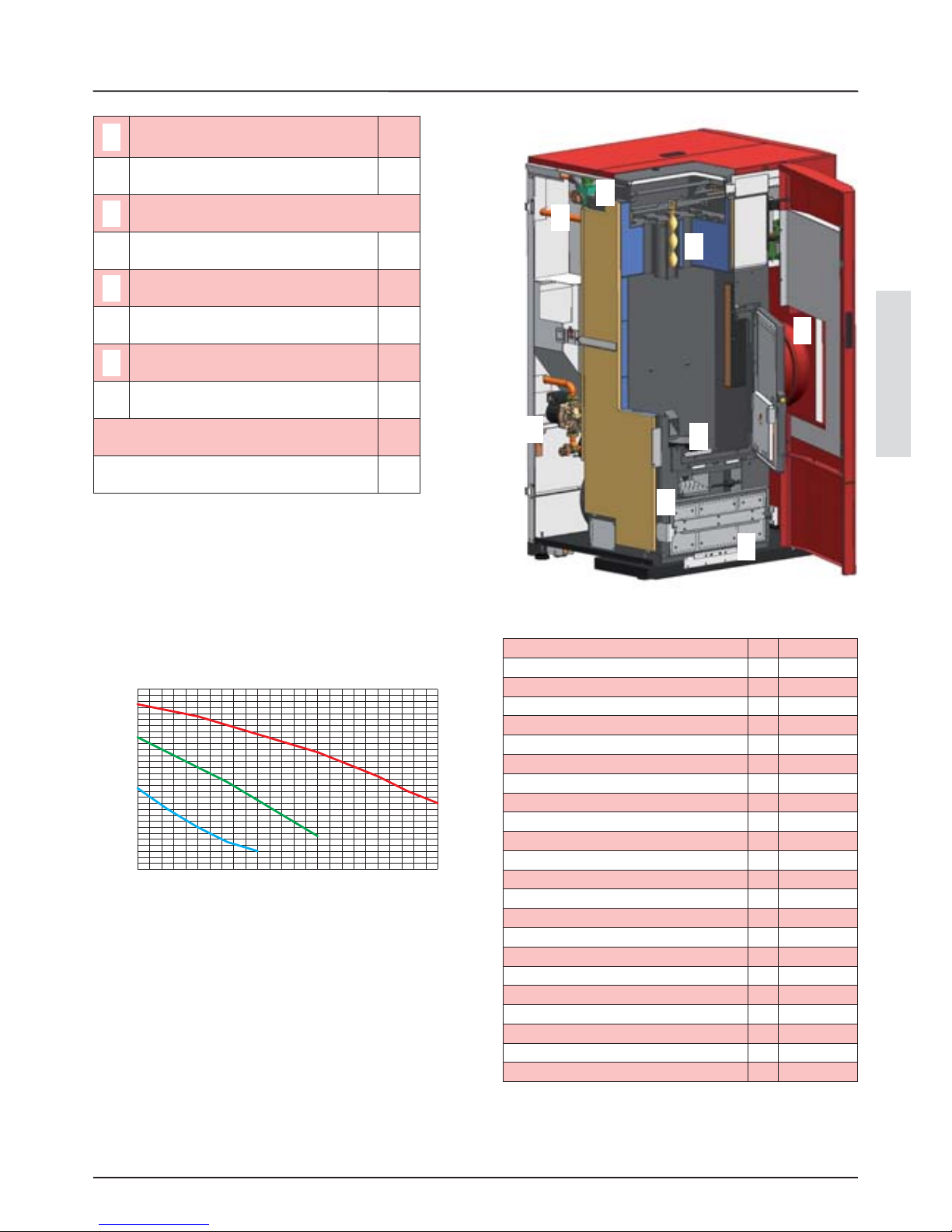
ENGLISH
0,0 0,5 1,0 1,5 2,0 2,5
0
1
2
3
4
5
6
1
2
5
3
4
6
7
8
FEATURES
29
kg
333
mm
1406
mm
875
mm
772
mm
120
mm
60
kW
33.8
kW
31.1
kW
10.0
kW
8.6
kg/h
7.0
kg/h
2.0
kg
~ 85
Pa
~ 10
W
470
W
470
Vac
230
Hz
50
“
1
“
1/2
m
5
bar
2.5
bar
0.6
FEATURES
The graphics given below illustrate the behaviour of the pump
used on our thermo-products at the speeds that can be set.
1
Pump integrated in the thermo product
with 5 m head
yes
2
Volume of expansion vessel integrated into
thermo-product (l)
12
3
Burn pot
4
Automatic cleaning mechanism yes
5
Shell and tube turbulator cleaning yes
6
3 bar safety valve integrated into the
thermo-product
yes
7
Minimum and maximum pressure pressure
switch integrated into the thermo-product
yes
8
Ash drawer yes
Heat exchanger water content (l)
66
Maximum content of water in the system for
integrated expansion vessel (l)
170
Head (m)
Flow rate (m3/h)
Tests performed using wooden pellets as fuel, certi ed
according to ONORM M7135 DIN PLUS.
The data given above is indicative and not binding. The
manufacturer reserves the right to make any modi cations in
order to improve product performance.
Weight
Height
Width
Depth
Flue exhaust pipe diameter
Air intake pipe diameter
Max. global heat output
Max. useful heat output (to the water)
Minimum global heat output
Min. useful heat output
Max. hourly fuel consumption
Min. hourly fuel consumption
Feed-box capacity
Recommended flue draught
Nominal electric output
Appliance electrical power
Nominal voltage
Nominal frequency
Water inlet/outlet pipe diameter
Automatic exhaust pipe diameter
Pump head
Max. working water pressure accepted
Min. working water pressure accepted

SAFETY AND FUNCTIONING DEVICES
30
SAFETY AND FUNCTIONING DEVICES
SAFETY DEVICES LP30
Circuit board: intervenes directly by sending the product into alarm conditions until
complete cooling, in the case of: breakage of ue gas motor, pellet feed motor breakage,
black out (if more than 10 seconds), no ignition
*
Door micro switch: With the door open, the burn pot system functioning is blocked *
Electronic pressure switch: in the case of inadequate pressure, (air side) it takes the machine
to alarm conditions
*
2.5 A fuse: they protect the machine from overcurrents
2.5 A 250V
F (rapid)
85°C calibrated mechanical bulb with manual rearm: intervenes by blocking fuel feed
whenever the pellet tank t° reaches the limit of 85°C. Rearm must be performed by quali ed
sta and/or the manufacturer's technical after-sales assistance.
*
100°C calibrated mechanical bulb with manual rearm: intervenes by blocking the fuel feed
whenever the t° of the water inside the product is near to 100°. Rearm must be performed
after the boiler has cooled completely
*
Maximum pressure switch: installed in series in the electric energy power supply to the
pellet motor. If the pressure in the system exceeds 2.5 bar, manual rearm of the pressure switch
is triggered: Rearm must be performed by quali ed sta and/or the manufacturer's
technical after-sales assistance.
*
Minimum pressure switch: if the pressure in the plant is too low (below 0.6 bar) the boiler
goes into minimum pressure alarm
*
TABLE OF SAFETY DEVICES FOR CLOSED VESSEL SYSTEM AND NOT PRESENT IN THE PRODUCT
Safety valve *
Pump control thermostat *
Temperature indicator *
Acoustic alarm activation thermostat -
Adjustment automatic circuit breaker switch ( rmware board) *
Water overheating automatic circuit breaker block switch (block thermostat) *
Circulation system *
Expansion system *
Safety dissipation system incorporated with the generator with thermal safety valve (selfactivated), whenever the appliance does not have a temperature self-adjustment system.
Not necessary as the machine
has a t° self-adjusting system
and a block automatic circuit
breaker switch.
As per standard (*)
Not as per standard (-)

ENGLISH
GLOSSARY
31
SMOKE CHANNEL OR FITTING
Pipe or connecting element between heat generator appliance and chimney to evacuate combustion products.
CLOSED HEARTH APPLIANCE
Generator whose opening is only allowed for feeding the fuel during use.
BIOMASS
Biological material, excluding the material incorporated in geological formations and transformed into fossils.
BIOFUEL
Fuel produced directly or indirectly by biomass.
CHIMNEY
Vertical pipe with the aim of collecting and expelling the fuel products coming from only one appliance, at a convenient height
from the ground.
INSULATION
Group of set-ups and materials used to prevent the transmission of heat through a wall that separates rooms with di erent
temperatures.
CHIMNEY CAP
Device positioned at chimney peak to ease the dispersion of combustion products into the atmosphere.
CONDENSATE
Liquid products that form when the combustion gas temperature is lower or equal to the water dew point.
HEAT GENERATORS
Appliance which allows to produce thermal energy (heat) through the rapid transformation, via combustion, of the chemical
energy of the same fuel.
GATE VALVE
Mechanism for modifying the combustion gas dynamic resistance.
COMBUSTION PRODUCT EVACUATION SYSTEMS
Flue gas exhaust system independent from the appliance constituted by a tting or smoke channel, chimney or individual ue
and chimney cap.
FORCED DRAUGHT
Air circulation by means of the fan activated by electric motor.
NATURAL DRAUGHT
Draught which is determined in a chimney/ ue due to the e ect of the volume mass di erence existing between combustion
products (hot) and surrounding atmosphere air, without any mechanical intake aid installed inside it or at its peak.
RADIATION AREA
Area immediately near the hearth in which the heat caused by combustion is di used, where there must be no combustion
materials .
REFLUX AREA
Area where leaking of the combustion products is veri ed, from the appliance towards the installation room.
GLOSSARY

45°
<
45°
<
INSTALLATION
32
For the heat generator appliances equipped with electric
fan for expelling combustion products, the instructions
below must be followed:
The horizontal routes will have to have a minimum
upward slope of 3%
The length of the horizontal route must be minimal and,
however, not longer than 3 metres
The number of direction changes including the one for
e ect of using the "T" element must not be more than 4 (if
4 bends are used, use double wall piping with an internal
diameter of 120 mm).
In any case, the smoke channels must seal the combustion and
condensate products and be insulated if they pass outside the
installation room.
The use of counterslope elements is forbidden.
The smoke channel must allow the recovery of soot or be
brushable.
The smoke channel must have constant section. Any section
changes are only allowed at the ue coupling.
It is forbidden to have other air supply channels and pipes for
plant engineering, especially if over-sized, transit inside the
smoke channels. The mounting of manual draught adjustment
devices on forced draught appliances is forbidden.
CHIMNEY OR INDIVIDUAL FLUE
The chimney or individual ue must respond to the following
requisites:
seal the combustion products, be waterproof and adequately
insulated in line with the use conditions;
be realised with materials which resist the normal mechanical
stress, heat, action of the combustion products and any
condensate;
have mainly vertical progress with deviations from the axis
not greater than 45°;
be adequately distanced from fuel or ammable materials
through air space or opportune insulation;
have preferably circular internal section: the square or
rectangular sections must have round corners with a radius not
lower than 20 mm;
have constant internal section, free and independent;
have rectangular section with max. ratio between the sides
of 1.5.
Insulating product
Flue
Inspection
The installation must be in compliance with:
UNI 10683 (2005) heat generators fed with wood and other
solid fuels: installation.
The chimneys must be in compliance with:
EN 13384-1 (2006) Thermal and uid dynamic calculation
methods.
UNI 1443 (2005) chimneys: general requisites.
UNI 1457 (2004) chimneys: clay/ceramic ue liners.
UNI TS 11278 (2008) metal chimneys and ues
The installation must be preceded by checking the positioning of
the chimneys, ues or discharge terminals of appliances on the
basis of:
Installation prohibitions
Legal distances
Limitations disposed by local administrative regulations or
particular authority prescriptions.
Conventional limitations deriving from condominium
regulations, constraints or contracts.
INSTALLATIONS ALLOWED
Only sealed appliances with respect to the room or which do
not place the room in depression with respect to the external
environment, can exist or be installed in the room where the
heat generator will be installed.
Appliances for cooking food and relative hoods without
extractor are only allowed in kitchens.
INSTALLATIONS NOT ALLOWED
In the room where the heat generator will be installed the
following must not pre-exist or be installed:
hoods with extractor
collective type ventilation pipes.
Should these appliances be in rooms adjacent, communicating
with the installation room, the simultaneous use of the heat
generator is forbidden, where a risk exists of one of the two
rooms being placed in depression respect to the other.
SMOKE CHANNEL OR FITTINGS
To mount the smoke channels, non- ammable elements will
have to be used, ideal for resisting combustion products and
their eventual condensing. The use of exible metal and asbestos
cement pipes to connect the appliances to the ue is forbidden,
even for pre-existing smoke channels. There must be continuity
between the smoke channel and the ue so that the ue does not
lean on the generator. The smoke channels must not cross rooms
where the installation of the combustion appliances is not allowed.
The smoke channels must be mounted in order to guarantee
sealing against combustion products for the appliance functioning
conditions, limit the formation of condensate and avoid it being
transported towards the appliance.
The mounting of horizontal routes must be avoided. For appliances
where ceiling or wall non-coaxial discharges with respect to the
appliance combustion product outlet have to be reached, the
direction changes will have to realised using open elbows not
greater than 45° (see gures below).
INSTALLATION

ENGLISH
< 3 m
3 - 5 %
< 3 m
45°
45°
A
B
C
20 cm
INSTALLATION
33
Chimney cap
wind-proof
Flue
pipe
Inspection
It is recommended that the smoke pipe be equipped with a
collection chamber for solid materials and any condensate situated
under the smoke channel inlet, so that it can be easily opened and
inspected from airtight door.
CONNECTION OF THE APPLIANCE TO THE FLUE
The ue must receive the discharge from only one heat generator.
The direct discharge towards closed spaces is forbidden, even
with clear sky.
EVACUATION OF THE COMBUSTION PRODUCTS
The direct discharge of the combustion products must be at
roof and the smoke pipe must have the features provided in the
"Chimney or individual ue" section.
External pipe
that is isolated
Inspection
Inspection
Inspection
CONNECTION TO EXTERNAL AIR INLETS
The appliance must be able to use the necessary air to guarantee
regular functioning through external air inlet. The air inlets must
comply with the following requisites:
1. have a total free section of at least 80 cm.
2. must be protected by grates, metal net or suitable protections as
long as they do not reduce the minimum section stated in point 1
and positioned in order to avoid them being obstructed.
If the combustion agent air is withdrawn directly from outside
through a pipe, a downward bend must be mounted outside
or a protection against the wind and no grates or similar must
be positioned. (it is recommended that the air vent always
REFERENCES Minimum distance
A 500 mm
B 700 mm
C 500 mm
Minimum
80 cm
2
Floor-protection
communicates directly with the installation room even if the air
is withdrawn from outside through a pipe). The air ow can also
be obtained from an adjacent room, as long as the ow takes
place freely through permanent openings communicating with
the outside. The adjacent room, with respect to the installation
room, must not be put in depression with respect to the external
environment by means of reverse draught caused by the presence
of another used appliance or intake device in such room. The
permanent openings in the adjacent room must comply with the
above-described requisites. The adjacent room cannot be set up
as garage, storage for combustion material or activity with danger
of re.
SAFETY RECOMMENDATIONS
The coverings, independently from the materials from which they
are made, must constitute a self-supporting construction with
respect to the heating block and not be in contact with it. The cross
members and nishings in wood or combustion materials must
be positioned outside the hearth radiation area or adequately
insulated. If coverings in combustion material or sensitive to heat
exist in the space above the generator, an insulating and non
combustible protection diaphragm must be inserted. Elements
in combustible or in ammable material like wooden furniture,
curtains, etc., directly exposed to the hearth radiation, must be
positioned at a safe distance. The appliance installation must
guarantee easy access for cleaning the appliance itself, discharge
gas pipe and ue.
NATIONAL, REGIONAL, PROVINCIAL AND TOWN
COUNCIL REGULATIONS
It is necessary to bear in mind all laws and national, regional,
provincial and town council Standards present in the country the
appliance has been installed.

50 cm
< 5 m
> 5 m
< 5 m
50 cm
H min
β
THE PELLETS
34
The pellets used must comply with the features described by the Standard:
Ö-Norm M 7135
DIN plus 51731
UNI CEN/TS 14961
WARNINGS: The use of expired pellets or any other material, damages the functions of your product and can determine the
invalidity of the warranty and the annexed responsibility of the manufacturer. To guarantee combustion without problems, the
pellets must be kept in a dry place. We recommend the use of pellets with diameter of 6mm with our products. See the images below for
feeding pellets.
THE PELLETS
CHIMNEY CAP
The chimney cap must comply with the following requisites:
have an internal section equivalent to that of the chimney;
have useful outlet section not lower than double the chimney internal section;
be built in order to avoid rain, snow, foreign bodies penetrating the chimney and so that, in the event of winds in any
direction and inclination, the discharge of the fuel products is assured.
be positioned in a way to guarantee an adequate dispersion and dilution of the combustion products and, however, outside
the re ux area in which the formation of counterpressures occurs. Such area has di erent dimensions and con guration
depending on the covering inclination angle. It is therefore necessary to adopt the minimum heights indicated in the gure
layouts below.
The chimney cap must not have mechanical intake means.
Distance > A
Distance < A
50 cm over the ridge
REFLUX AREA
re ux area height
SLOPING ROOF
FLAT ROOF
CHIMNEY CAPS, DISTANCES AND POSITIONING
Roof
inclination
Distance between the
ridge and the chimney
Minimum chimney height
(measured from outlet)
β A (m) H (m)
15°
< 1,85 0.50 m over the ridge
> 1,85 1.00 m from roof
30°
< 1,50 0.50 m over the ridge
> 1,50 1.30 m from roof
45°
< 1,30 0.50 m over the ridge
> 1,30 2.00 m from roof
60°
< 1,20 0.50 m over the ridge
> 1,20 2.60 m from roof

ENGLISH
INSTALLATION AND HYDRAULIC PLANT SAFETY DEVICES
35
INSTALLATION AND HYDRAULIC PLANT SAFETY DEVICES
During installation of the boiler it is MANDATORY to insert
a manometer into the system in order to display the water
pressure. The installation, relative system connections,
commissioning and inspection of correct functioning must
be carried out perfectly, in total compliance with Standards in
force, both national, regional and municipal, as well as these
instructions.
For Italy, installation must be carried out by professionally
authorised sta (Ministerial Decree dated 22.01.08 n°37).
The company declines all responsibility for damage/injury
to objects and/or persons caused by the system.
SAFETY DEVICES FOR CLOSED VESSEL SYSTEM
According to the UNI 10412-2 (2006) Standard in force in
Italy, the closed systems must have: safety valve, pump
control thermostat, acoustic alarm activation thermostat,
temperature indicator, pressure indicator, acoustic alarm,
regulation automatic circuit breaker switch, automatic circuit
breaker block switch (block thermostat), circulation system,
expansion system, safety dissipation system incorporated
with the generator with thermal safety valve (self-activated),
whenever the appliance does not have a temperature selfadjustment system.
DISTANCES OF SAFETY DEVICES ACCORDING TO THE
STANDARD
Component Distance
Temperature safety sensors
On the machine or not
exceeding 30 cm
Missing devices because not
as per standard
Not exceeding one metre, on
the ow pipe
The temperature safety sensors must be in place on the
machine at a distance no greater than 30 cm from the ow
connection.
Whenever the generators lack a device, those missing can
be installed on the generator ow pipe, within a distance no
greater than 1m from the machine.
The domestic heating appliances with automatic feeding
must: be supplied with a fuel block thermostat or be supplied
with a cooling circuit set-up by the appliance manufacturer.
The cooling circuit must be activated by a heat safety valve
such to guarantee that the limit temperature set by the
Standard is not exceeded.
Connection between the power supply unit and the valve
must be free from interceptions.
The pressure upstream from the cooling circuit must be at
least 1.5 bar.
HYDRAULIC PLANT
Certain concepts referring to the Italian UNI 10412-2 (2006)
Standard are described in this chapter. As previously described,
when installing, all national, regional, provincial and town
council Standards in force provided by the country in which
the appliance has been installed must be complied with.
TYPE OF SYSTEM
There are two di erent types of system: open vessel system and
closed vessel system. The product has been designed and realised
to work with closed vessel systems.
CLOSED VESSEL SYSTEM FOR AUTOMATIC LOADING
APPLIANCES
System in which the water it contains is not in direct or indirect
communication with the atmosphere. Generally, the closed
vessel system has one of the following expansion vessels:
Pre-loaded closed expansion vessel with membrane
impermeable to the passage of gases.
Automatic closed expansion system with compressor
and membrane impermeable to the passage of gases.
Automatic closed expansion system with transfer pump
and membrane impermeable to the passage of gases.
Expansion system without diaphragm.
COMMISSIONING CHECKS
Before connecting the boiler:
a) wash all system piping in order to remove any residues
which might compromise the correct functioning of certain
system components (pumps, valves, etc.).
b) check to verify that the ue has adequate draft, is not
narrowed and that other appliances do not discharge into the
ue.
Only after this control can the chimney tting between the
boiler and ue be mounted. It is recommended to control the
ttings with pre-existing ues.
FEEDING WATER FEATURES
The chemical-physical features of the system and reinstate
water are fundamental for the correct functioning and lifespan of the boiler.
Amongst the inconveniences caused by bad quality feeding
water, the most frequent is the scaling of the heat exchange
surfaces.
Less frequent, but equally serious, is the corrosion of the water
side surfaces of the entire circuit.
It is known that the lime scale, even if there is only a few
millimetres, due to their low thermal conductivity, greatly
reduce the heat exchange, determining damaging localised
heating. It is strongly recommended to treat the water in the
following cases:
a) very hard water available (higher than 20°f)
b) very extended systems
c) large water quantities restored due to leaks
d) subsequent llings due to system maintenance work
It is recommended to always contact specialised companies to
treat the feeding water of the heating systems.

A
B
C
D
E
1
2
3
INSTALLATION AND HYDRAULIC PLANT SAFETY DEVICES
36
FILLING THE SYSTEM
Once the hydraulic connections have been carried out,
connect the system. Open all air venting valves of radiators,
boiler and system. Gradually open the load cock ensuring that
the air venting valves work regularly. Using the manometer,
check that the system is pressurised. In case of closed vessel
system, reach the pressure of about 0.11 – 0.12 MPa (1.1 – 1.2
bar). For open vessel systems, the pressure in the lowest part
of the boiler is given by the height of the vessel. Close the load
cock and again release the air from the boiler through the
venting valve.
AUTOMATIC THERMOSTATIC MIXER VALVE
MANDATORY
The automatic thermostatic mixing valve nds applications
in solid fuel boilers as it prevents cold water return into the
exchanger. Routes 1 and 3 are always open and, together
with the pump installed on the return, they guarantee water
circulation inside the biomass boiler exchanger. An elevated
return temperature, allows e ciency improvement, reduces
formation of combustion product condensation and prolongs
the boiler life span. Valves on the market have di erent
calibrations. Extra ame advises use of 55°C model with 1"
hydraulic connections. Once the valve calibration temperature
is reached, route 2 is opened and the boiler water goes to the
system via the ow. Extra ame recommends not to use this
device whenever the DHW is produced through an instant
heat exchanger.
automatic
thermostatic
mixer valve
55°C
Safety valve
discharge
Thermometer
Manometer
Return
Flow
Flow
A = primary air Ø 60 mm
B = ue gas exhaust pipe Ø 120 mm
C = boiler 1“ ow/outlet
D = boiler 1“ return/inlet
E = 3 bar 1/2 “ safety drain
Balance
Valve
system loading unit

ENGLISH
85°C
4
29 / 04 /2010
18 : 56
STBY
SABATO
-
+
DISPLAY: CONTROL BOARD
37
P1 P2 P3
P1
P2
P3
*
DISPLAY: CONTROL BOARD
set
temper.
Inlet
USB
auto/man
mode
stby
pump
Power
set
W ater T°
*The ame icon is not present in the OFF, START, BURN POT CLEANING, FINAL CLEANING, ALARM, RE-START STBY
states
*Flashes in IGNITION mode
*Fixed in START and WORK mode. During the WORK phase it displays the ame with real work power
P1 P2 P3
Boiler ignition or switch-o key
P1
Encoder (wheel), by turning, select the di erent icons on the display, by pressing enter selection
P2
Multiple-function key (advancement through menus etc)
P3
*
WORK
state display
DHW Storage Management *
Pu er Management *
3 heating areas *
Instant DHW option *
Pu er pump or 4th heating area management *
Anti-legionella management for DHW storage *
DHW storage chrono management *
Auxilliary output management and control *
Extra ame has an optional
additional board that allows
the boiler the following further
functions when managing the
system.
set
power
regolat.
user
state
set
user
set
installat.
day, date and time
Power
real

FUNCTIONING
38
FUNCTIONING
The boiler performs the following phases: START, BURN POT CLEANING, IGNITION, START-UP and FUNCTIONING.
During the BURN POT CLEANING several trapdoor blows occur, i.e. automatic cleaning of the burn pot to allow excellent
functioning. During the IGNITION phase, the pellet fed is burned, thanks to the heat introduced into the burn pot by the electric
resistance. When ignition has taken place, the boiler passes to START-UP, work preparation phase. In the “FUNCTIONING” phase
the user can set the power and the desired temperature of the water. The higher the power, the greater the speed of the product
itself in reaching normal working conditions of the system.
IGNITION
Press key P1 for 3 seconds. During the rst switch-ons, it is possible that slight odours are produced due to the drying of the
paints and silicones used. Avoid long stays and air the room. After an initial check-up, the machine will start to clean the burn
pot, by striking the trapdoor and then starts the IGNITION process,following these 3 points:
1.Power supply to the ign-plug
2.Power supply to the pellet feed motor
3.Start-up of the fumes motor.
If the machine has not ignited, the
NO IGNITION alarm occurs.
In the event of the alarm due to no ignition:
wait for the machine to cool (green screen)
press key P1 for 3 seconds.
WORKING
The boiler will work to reach the water temperature set by the user. The pump will start to function as soon as the factory-set
parameters are reached. An always open heating area is recommended to make the product functioning homogenous, avoiding
overheating blocks The boiler will automatically modulate when approaching the temperature set, going to minimum power
and then switching-o (H o ) if it will exceed the set over the factory set-parameters. When the water temperature drops, the
boiler will re-start.
Nota bene: the general times of the various functioning states are variable on the basis of the type of system and on the
basis of the parameters set.
SWITCHOFF
Switch-o can take place manually by pressing key P1 for three seconds, automatically (due to a control programmed from the
utility in automatic mode), due to a contact of an additional external thermostat satis ed or H OFF. i.e. temperature of the water
reached and exceeded.
ADDITIONAL THERMOSTAT STBY
The product can also function with the additional thermostat. The
state of the contact will be shown on the display. If satis ed, the
thermostat, switches the boiler o , showing STANDBY on the
display.
As soon as the thermostat goes back to request mode, the boiler
will re-ignite (as long as a H OFF state is not present, i.e. mandatory
switch o due to the boiler water temperature over the limit set by
the user and the factory parameters). In the case of H OFF, as soon
as the water has dropped below the factory levels set, ignition will
take place.
2 speaker clamps are present in the rear. The speaker clamp jumpered in the factory and indicated with STBY (reference
number 2) is that for the additional thermostat. The clamp with the wording AUX (reference number 1) is used to connect the
optional additional board).
Recommendations: position the external thermostat away from heat sources, at a height of about 1.5 m.
1
2
Closed contact (on request) = automatic ignition
Open contact (satis ed) = automatic switch o

ENGLISH
-
MENU
39
TEMPERATURE
SET POWER
USER REGULATION
STATUS
SET USER
SET CLOCK
SET CHRONO
LANGUAGE
SET HEAT
EXCHANGER
SET CLOCK
MENU
INSTALLER*
MANUAL/
AUTOMATIC
PELLET
REGULATION
SET H2O
STOVE STATUS
SET CHRONO
LANGUAGE
SET HEAT
EXCHANGER
* SET INSTALLER: this menu is reserved for the after sales
SET POWER

85
SET H20
c
°
05
P1 P2 P3
P1 P2 P3
MENU
40
From the main screen, turn P2 to select the icon
Press P2 to con rm
Turn P2 to regulate the temperature
Con rm and memorising by pressing P2
To exit without memorising, press key P1
TEMPERATURE REGULATION
SET POWER
From the main screen, turn P2 to select the icon
Press P2 to con rm
Turn P2 to regulate the power
Con rm and memorising by pressing P2
To exit without memorising, press key P1
POWER REGULATION

ENGLISH
-
-
P1 P2 P3 P1 P2 P3
P1 P2 P3
MENU
41
The set user menu o ers the following possibilities
automatic/manual mode: allows enabling/disabling of the chrono inside the boiler
pellet regulation: allows pellet regulation
The automatic mode allows to ignite the boiler and switch it o , following the programming set by the user. To regulate the time
periods, see the CHRONO REGULATION paragraph.
From the main screen, turn P2 to select the icon
Press P2 to con rm
Turn P2 to take chrono enabling to ON
Con rm and memorising by pressing P2
to exit without memorising, press key P1
OFF
ENABLE CHRONO
ON
ENABLE CHRONO
From the main screen, turn P2 to select the icon
Press P2 to con rm and successively press P2 again to
select PELLET REGULATION
Turn P2 to modify the parameter as a percentage
(-20/+20)
Con rm and memorising by pressing P2
to exit without memorising, press key P1
-20%
PELLET REGULATION
The boiler allows regulation of the pellets via the relative menu. Considering the di erent types of pellets on the market, the
user can increase or decrease the amount of pellets as a percentage.
USER REGULATIONS MENU
PELLET REGULATION
AUTOMATIC/MANUAL MODE

MENU
42
MOTOR...
OUT 2...
PEL MOTOR...
IGNPLUG...
The set user menu o ers the following possibilities:
set clock: allows regulation of the time and date
set chrono: allows to program 4 functioning time periods for the boiler, with automatic switch-ons and switch-o s and
setting of the desired water temperature for every time period.
language: setting the desired language (Italian, English, French, German, Spanish)
set heat exchanger: programming of the start and end times of the automatic cleaning of the heat exchangers.
STATE MENU
The state menu is used to display the state of the inputs and outputs in the board
From the main screen, turn P2 to select the
p
p
icon
Press P2 to con rm (display of STATE 1 screen)
Press P2 again to display STATE 2 screen
To go back, press P3
To exit, press key P1
P1 P2 P3
STATE 1 LP30
REVS
T FUMES
T H2O..
P1 P2 P3
STATE 2 LP30
SET USER

ENGLISH
MENU
43
USER MENU
SET CLOCK
SET CHRONO
LANGUAGE
SET HEAT EXCHANGER
SET CLOCK
DAY
HOURS
MINUTES
DATE
MONTH
YEAR
SATURDAY
23
21
04
06
10
From the main screen, turn P2 to select the icon
Press P2 to con rm
Turn P2 to select “ SET CLOCK”
Con rm, pressing P2
Turn P2 to select the desired parameter
Press P2 to enter modi cation mode
Turn P2 to modify the value
Press P2 to con rm and exit
If you wish to exit without memorising, press key P1
P1 P2 P3
P1 P2 P3
SET CLOCK
CHRONO REGULATION
Through regulation of the chrono, i.e. automatic mode, the boiler can ignite and switch o in automatic mode. The chrono has
absolute priority over every control, therefore this factor must be considered. Four time periods can be programmed. By default
all of the time periods are in OFF
START PRG1
STOP PRG1
MONDAY PRG1
TUESDAY PRG1
WEDNESDAY PRG1
THURSDAY PRG1
FRIDAY PRG1
SATURDAY PRG1
SUNDAY PRG1
SET PRG1
00:00
00:00
ON
OFF
OFF
OFF
OFF
OFF
OFF
...
First time period ignition time
First time period switch-o time
day allowed or not (on - o )
day allowed or not (on - o )
day allowed or not (on - o )
day allowed or not (on - o )
day allowed or not (on - o )
day allowed or not (on - o )
day allowed or not (on - o )
setting water t°
EXPLANATION
SCREEN

MENU
44
P1 P2 P3 P1 P2 P3
Turn P2 to select the icon
Press P2 to con rm
Turn P2 to select “ SET CHRONO”
Con rm, pressing P2
Turn P2 to select the desired parameter
Press P2 to enter modi cation mode
Turn P2 to modify the value
Press P2 to con rm and exit
If you wish to exit without memorising, press key P1
SET CLOCK
SET CHRONO
LANGUAGE
SET HEAT EXCHANGER
USER MENU
LANGUAGE
ITALIAN
SET LANGUAGE MENU
The boiler allows to set the following languages: Italian, English, French, German and Spanish.
ITALIAN is the default setting
Turn P2 to select the icon
Press P2 to con rm
Turn P2 to select “ LANGUAGE”
Con rm, pressing P2
Turn P2 to select the desired parameter
Press P2 to enter modi cation mode
Turn P2 to modify the value
Press P2 to con rm and exit
If you wish to exit without memorising, press key P1
P1 P2 P3 P1 P2 P3
SET CLOCK
SET CHRONO
LANGUAGE
HEAT EXCHANGER
START PRG1
STOP PRG1
MONDAY PRG1
...
SET USER
SET CHRONO

ENGLISH
MENU
45
SET HEAT EXCHANGER MENU
SET CLOCK
SET CHRONO
LANGUAGE
SET HEAT
EXCHANGER
USER MENU
This menu allows to program the start and end time of automatic cleaning of the heat exchanger. Cleaning takes place
mechanically via metal springs that clean the exchange pipes. By default the parameters are START 6:00 STOP 22:00 which mean
that cleaning is excluded from 22 to 6 in the morning.
START .. 00:00
STOP .. 00:00
Turn P2 to select the icon
Press P2 to con rm
Turn P2 to select “ SET HEAT EXCHANGER”
Con rm, pressing P2
Turn P2 to select the desired parameter
Press P2 to enter modi cation mode
Turn P2 to modify the value
Press P2 to con rm and exit
If you wish to exit without memorising, press key P1
SET HEAT
EXCHANGER

29 / 04 /2010
18 : 56
-
STBY
SABATO
-
+
ALLARME ATTIVO
29 / 04 /2010
18 : 56
-
STBY
SABATO
-
+
MEMORIA ALLARME
“TIPO DI ALLARME”
SIGNS TABLE
46
P1 P2 P3
SIGNALS
Display Meaning Explanation
START The start phase is in progress -
PELLET LOADING
the continuous feeding of the pellets during the ignition
phase is in progress
-
IGNITION The boiler is in ignition phase -
START the work preparation phase is in progress -
WORKING
the normal working phase is in progress, the boiler is
working at the power set
-
BURN POT CLEANING the automatic burn pot cleaning is in progress -
FINAL CLEANING the nal cleaning is in progress -
MODULATION the boiler is working at minimum power -
STAND BY boiler waiting for re-ignition due to an external thermostat
the boiler will only re-start when the external
thermostats makes a request
WAIT COOL BLACK OUT the boiler is cooling after a power cut.
once cooling is completed it will automatically
ignite
HOFF
Boiler in stand-by for re-ignition because the water inlet
temperature has exceeded the parameters set
as soon as the water temperature drops below the
pre-established parameters, the boiler will switch
back on
ANTIFREEZE
the anti-freeze function is in progress as the H2O t° is below
the factory set threshold
the pump is active until the water reaches the preset factory parameter
ANTILOCK
If the boiler has remained in the O state for at least 96
hours, the pump starts to function, so that blocking does not
occur.
the pump activates for a brief period, in a way to
prevent blockage of the same.
EXCH. BLOCK indicates the cleaning block of the exchanger contact after-sales centre
SIGNS TABLE
ALARM
When the boiler goes into alarm mode, the screen becomes red and does not accept commands outside of the display. When
the scree turns green, “ALARMS MEMORY” will be displayed with the type of alarm and the boiler can respond to controls
not from the display. If the alarm can be solved by the user, once this has been performed the boiler can be re-ignited by
pressing the P1 key. In the event of a more complex alarm, contact the after-sales assistance.
P1 P2 P3
ACTIVE ALARM
ALARM MEMORY
“TYPE OF ALARM”
SATURDAY
SATURDAY

ENGLISH
ALARMS TABLE
47
ALARMS
Display Reason Solution
Indicates the presence of an alarm.
To reset the alarm, just hold "ignition/switch-off" for 3 seconds
when the boiler is cold.
FAN FAILURE Flue gas motor fault contact after-sales centre
FLUE PROBE Flue gas probe fault. contact after-sales centre
HOT FUMES High flue gas temperature
check the calibration of pellet regulation. If this cannot be solved,
contact an authorised technician
NO FLOW ALARM
The door is not closed correctly.
The ash drawer is not closed
correctly.
The combustion chamber is dirty.
The flue exhaust or air supply pipe
is blocked.
Check hermetic door closure.
Check hermetic closure of the ash drawer.
Check cleanliness of the fumes pipe and the combustion chamber.
Check cleanliness if the air supply pipe and the flow sensor
NO IGNITION
The pellet feed-box is empty.
Pellet feed calibration inadequate.
Check for the presence of pellets in the feed-box.
Regulate the pellet flow
Check the procedures described in the “Ignition” chapter.
BLACKOUT NO IGN.
No current during the ignition
phase.
Take the boiler to OFF conditions using key 1 and repeat the
procedure described in the "Ignition" chapter.
NO PELLETS
The pellet feed-box is empty.
No pellet feed.
The motor reducer does not feed
pellets.
Check for the presence of pellets in the feed-box.
Adjust pellet flow (see “Pellet feed adjustment”).
DEPR ALARM
The door is not closed correctly.
The ash drawer is not closed
correctly.
The combustion chamber is dirty.
The flue exhaust pipe is blocked
Check hermetic door closure.
Check hermetic closure of the ash drawer.
Check cleanliness of the fumes pipe and the combustion chamber.
Check the mechanical pressure switch (air side)
DEPR SENSOR DAMAGE
flow sensor faulty
sensor disconnected
contact after-sales centre
H2O OVERTEMP ALARM
the water in the boiler has
exceeded 95°C.
Possible air in the system.
Insufficient circulation.
No or inadequate safety zone.
Possible pump anomaly.
contact after-sales centre
MINIMUM PRESSURE
ALARM
the system pressure read by the
pressure switch is too low.
Possible presence of air in the
system.
Possible lack of water or leaks
due to anomalies in some system
component.
contact after-sales centre
TRAPDOOR BLOCK
The automatic cleaning of the burn
pot results blocked.
Switch off the machine, wait for complete cooling and repeat the
ignition cycle.
If the problem persists, the reset operations must be carried out by
an authorised technician.
WATER PROBE H2O probe faulty contact after-sales centre
ALARMS TABLE

BOILER CLEANING
48
BOILER CLEANING
Maintenance operations guarantee correct functioning of the product through time. Failure to comply with these operations
can jeopardise the safety of the product.
BURN POT CLEANING
The burn pot is cleaned via a mechanical system at pre- xed intervals automatically by the boiler. The gure below shows the
burn pot with underlying opening.
The company recommends the removal of ash deposits using a suction device at least once every two days, or however, on the
basis of use of the product.
* The image could be slightly di erent to the original product.
LP30 ASH DRAWER
With machine o , open the ash drawer to empty the content. The frequency of emptying the ash drawer will be proportional to
the use of the product. Lp30 has 3 drawers.
DOOR GASKET AND ASH DRAWER
The gaskets guarantee the tightness of the boiler and its consequent good functioning.
These must be checked regularly: if they should be worn or damaged they must be replaced immediately.
These operations must be carried out by an authorised technician.
N.B. For correct functioning, the boiler must undergo routine maintenance by an authorised technician, at least once a
year.
If the power supply cable is damaged, it must be replaced by the after-sales service or by a similarly quali ed person, so as to
avoid al risks.
CLEANING THE FLUE
Suck and clean the pipe that leads to the ue yearly or anytime that it is necessary. If there are horizontal tracts the residues must
be removed before they obstruct smoke passage. NON-CLEANING jeopardises safety.

FRANÇAIS
1
2
5
3
4
6
7
8
0,0 0,5 1,0 1,5 2,0 2,5
0
1
2
3
4
5
6
CARACTERISTIQUES
49
kg
333
mm
1406
mm
875
mm
772
mm
120
mm
60
kW
33.8
kW
31.1
kW
10.0
kW
8.6
kg/h
7.0
kg/h
2.0
kg
~ 85
Pa
~ 10
W
470
W
470
Vac
230
Hz
50
“
1
“
1/2
m
5
bars
2.5
bars
0.6
CARACTERISTIQUES
La graphique gurant ci-dessous illustre le compor tement du circulateur
utilisé sur nos produits thermiques aux vitesses con gurables.
1
Circulateur intégré sur le produit thermique
avec hauteur d'élévation 5m
oui
2
Volume vase d'expansion intégré sur le
produit thermique (l)
12
3
Brasier
4
Mécanisme de nettoyage automatique
oui
5
Turbulateur nettoyage du faisceau des
tubes
oui
6
Soupape de sécurité 3 bars intégrée sur le
produit thermique
oui
7
Pressostat de minimum et de maximum
intégré sur le produit thermique
oui
8
Tiroir à cendres
oui
Contenu d'eau échangeur (I)
66
Contenu maximum d'eau de l'installation pour
vase d'expansion intégré (I)
170
Hauteur d'élévation (m)
Débit (m3/h)
Tests e ectués en utilisant des pellets de bois comme
combustible certi és selon la ONORM M7135 DIN PLUS.
Les données reprises ci-dessus sont fournies à titre indicatif et
n'engagent en rien. Le fabricant se réserve la faculté d'apporter
toute modi cation nécessaire a n d'améliorer les performances
du produit.
Poids
Hauteur
Largeur
Profondeur
Diamètre du tuyau d'évacuation des fumées
Diamètre du tuyau d'aspiration de l'air
Puissance thermique globale max.
Puissance thermique utile max (fournie à l'eau)
Puissance thermique globale min.
Puissance thermique utile min.
Consommation horaire combustible max.
Consommation horaire combustible min.
Capacité du réservoir
Tirage conseillé de la cheminée
Puissance électrique nominale
Puissance électrique appareil
Tension nominale
Fréquence nominale
Diamètre du tuyau d'entrée/sortie de l'eau
Diamètre du tuyau de vidange automatique
Hauteur d'élévation de la pompe
Pression hydre max. d'exercice admise
Pression hydrique min. d'exercice admise

DISPOSITIFS DE SECURITE ET FONCTIONNEMENT
50
DISPOSITIFS DE SECURITE ET FONCTIONNEMENT
DISPOSITIF DE SECURITE LP30
Carte électronique: elle agit directement mettant le produit ni en alarme jusqu'à ce qu'il
soit complètement refroidi en cas de: rupture du moteur des fumées, rupture du moteur de
chargement du pellet, black-out (si supérieur à 10 secondes), allumage raté
*
microrupteur porte: Avec la porte ouverte, le fonctionnement du système de nettoyage du
brasier est bloqué
*
Pressostat électronique: en cas de pression (côté air) inadaptée il met la machine en alarme
*
Fusible 2,5 A : ils protègent la machine contre les surtensions
2.5 A 250V
F (rapide)
Bulbe mécanique réglé à 85°C à réarmement manuel: il agit en bloquant le chargement de
combustible si la température (t°) du réservoir de pellet atteint la limite de 85°C. Le réarmement
doit être e ectué par un personnel quali é et/ou assistance technique du fabricant
*
Bulbe mécanique réglé à 100°C à réarmement manuel: il intervient en bloquant le chargement
de combustible si la température (t°) de l'eau à l'intérieur du produit est proche de 100° . Le
réarmement doit être e ectué après que la chaudière ait complètement refroidi
*
Pressostat de maximum: installé en série sur l'alimentation d'énergie électrique au moteur
pellet; Si la pression dans l'installation dépasse 2,5 bars, le réarmement manuel du pressostat se
déclenche: Le réarmement doit être e ectué par un personnel quali é et/ou une assistance
technique du fabricant
*
Pressostat de minimum: si la pression dans l'installation est trop basse (inférieure de 0,6 bar), la
chaudière se met en alarme pression minimum
*
TABLEAU DES DISPOSITIFS DE SECURITE POUR INSTALLATION A VASE CLOS PRESENTS ET NON PRESENTS A BORD DU PRODUIT
Soupape de sécurité *
Thermostat de commande du circulateur *
Indicateur de température *
Thermostat d'activation de l'alarme acoustique -
Interrupteur thermique automatique de régulation ( rmware che) *
Interrupteur thermique automatique de blocage (thermostat de blocage)
surtempérature de l'eau
*
Système de circulation *
Système d'expansion *
Système de dissipation de sécurité incorporé au générateur avec vanne de décharge
thermique (à actionnement automatique), si l'appareil n'est pas doté d'un système de
régulation automatique de la température.
N'est pas nécessaire dans la
mesure où la machine est
pourvue d'un système de réglage
automatique de la température
et d'un interrupteur thermique
automatique de blocage.
De série (*)
Pas de série (-)

FRANÇAIS
GLOSSAIRE
51
CANAL DE FUMEE OU RACCORDEMENT
Conduit ou élément de raccordement entre un appareil générateur de chaleur et la cheminée pour l’évacuation des produits
de la combustion.
APPAREIL A FOYER FERME
Générateur dont l'ouverture est admise, pendant l'emploi, uniquement pour le chargement du combustible.
BIOMASSE
Matériel d'origine biologique, sauf le matériel incorporé dans des formations géologiques et transformé en fossile.
BIOCOMBUSTIBLE
Combustible produit directement ou indirectement par la biomasse.
CHEMINEE
Conduit vertical ayant pour but de recueillir et d’expulser, à une certaine hauteur du sol, les produits de la combustion provenant
d’un seul appareil.
CALORIFUGEAGE
Ensemble des systèmes et des matériaux utilisés pour empêcher la transmission de la chaleur à travers une paroi qui divise des
milieux à température di érente.
POT DE CHEMINEE
Dispositif placé au sommet de la cheminée prévu pour faciliter la dispersion des résidus de la combustion dans l'atmosphère.
CONDENSATION
Produits liquides qui se forment lorsque la température des gaz de combustion est inférieure ou égale au point de rosée de
l’eau.
GENERATEURS DE CHALEUR
Appareil qui permet de produire l’énergie thermique (chaleur) grâce à la transformation rapide, par combustion, de l’énergie
chimique du combustible.
BOUCHOIR
Mécanisme pour modi er la résistance dynamique des gaz de combustion.
SYSTEMES D'EVACUATION DES FUMEES
Installation pour l’évacuation des fumées indépendante de l’appareil constituée d’un raccordement ou d'un canal de fumée,
d'une cheminée ou d'un tuyau d'évacuation des fumées individuel et d'un pot de cheminée.
TIRAGE FORCE
Circulation d’air au moyen du ventilateur actionné par un moteur électrique.
TIRAGE NATUREL
Tirage qui a lieu dans une cheminée/tuyau d'évacuation des fumées à cause de la di érence de masse volumique existant entre
les fumées (chaudes) et l’air atmosphérique ambiant, sans aucune autre aide mécanique d’aspiration installée à l’intérieur ou
au sommet.
ZONE DE RAYONNEMENT
Zone immédiatement contiguë au foyer où se propage la chaleur provoquée par la combustion et dans laquelle ne doit se
trouver aucun matériau combustible.
ZONE DE REFLUX
Zone où a lieu l’échappement des produits de la combustion de l’appareil vers le local d’installation.
GLOSSAIRE

45°
<
45°
<
INSTALLATION
52
Pour les appareils générateurs de chaleur munis d’électro-
ventilateur pour l’expulsion des fumées, on devra respecter les
conditions suivantes:
Les sections horizontales devront avoir une pente minimum de
3% vers le haut
La longueur de la section horizontale doit être minimale et de
toute façon non supérieure à 3 mètres
Le nombre de changements de direction y compris par e et de
l'utilisation d'élément en "T" ne doit pas être supérieur à 4 (si l'on
utilise 4 coudes, utiliser des tuyaux à double paroi de 120 mm de
diamètre interne).
Dans tous les cas, les conduits de fumée doivent être étanches aux
produits de la combustion et des condensations et calorifugés s’ils
passent à l’extérieur du local d’installation.
L’utilisation d’éléments en contre-pente est interdite.
Le canal de fumée doit permettre la récupération de la suie ou
permettre le ramonage.
Le canal de fumée doit avoir une section constante. D'éventuels
changements de section sont admis au branchement du tuyau
d'évacuation des fumées.
Il est interdit de faire passer à l’intérieur des canaux de fumée, même
surdimensionnés, d’autres canaux d’adduction d’air et des tuyaux
d’installations industrielles. Le montage de dispositifs de réglage
manuel du tirage sur les appareils à tirage forcé n’est pas admis.
CHEMINEE OU TUYAU D'EVACUATION DES FUMEES
INDIVIDUELLE
La cheminée ou le tuyau d'évacuation des fumées doit répondre aux
conditions suivantes:
ils doivent être étanches aux produits de la combustion, imperméables
et calorifugés selon les conditions d’emploi ;
Ils doivent être réalisés en matériaux adaptés aux sollicitations
mécaniques normales, à la chaleur, à l’action des produits de la
combustion et aux éventuelles condensations;
ils doivent avoir un parcours principalement vertical avec des
déviations de l’axe non supérieures à 45°;
se trouver à une distance adéquate de matériaux combustibles
ou in ammables à l’aide d’un matelas d’air ou d’un isolant;
avoir une section interne préférablement circulaire: les sections
carrées ou rectangulaires doivent avoir des angles arrondis avec un
rayon supérieur à 20 mm.
avoir une section interne constante, libre et indépendante;
avoir les sections rectangulaires avec un rapport maximum
entre les côtés de 1,5.
Il est conseillé que le conduit de fumée soit muni d’une chambre de
Isolant
Tuyau
d'évacuation
de fumées
Inspection
L'installation doit être conforme à:
UNI 10683 (2005) Générateurs de chaleur alimentés au bois ou avec
d'autres combustibles solides: installation.
Les cheminées doivent être conformes à:
EN 13384-1 (2006) méthode de calcul des caractéristiques thermo-
aérauliques des cheminées.
UNI 1443 (2005) cheminées: conditions générales.
UNI 1457 (2004) cheminées: conduits internes en terre cuite et
céramique.
UNI TS 11278 (2008) cheminées et tuyaux d'évacuation métalliques
L’installation doit être précédée par une véri cation du positionnement des
cheminées, des conduits de cheminée ou des terminaux d’échappement
des appareils comme :
Interdictions d'installation
Distances légales
Limitations imposées par les règlements administratifs locaux ou
prescriptions particulières de l'autorité.
Limitations conventionnelles dérivant de règlement de co-
propriété, servitudes ou contrats.
INSTALLATIONS ADMISES
Dans le local où doit être installé le générateur de chaleur ne peuvent
préexister ou être installés que des appareils fonctionnant de façon
étanche par rapport au local ou qui ne mettent pas en dépression le local
par rapport au milieu externe.
Uniquement dans les cuisines, il est autorisé de mettre des appareils servant
à la cuisson des aliments avec leur hotte respective sans extracteur.
INSTALLATIONS NON ADMISES
Dans le local où doit être installé le générateur de chaleur ne peuvent
préexister ou être installés:
de hottes avec extracteur
de conduits de ventilation type collectif.
Si ces appareils se trouvent dans des locaux contigus communicant avec
le local d’installation, il est interdit d’utiliser en même temps le générateur
de chaleur s’il y a un risque qu’un des deux locaux soit mis en dépression
par rapport à l’autre.
CANAL DE FUMEE OU RACCORDS
Pour le montage des canaux de fumées, il faudra utiliser des éléments de
matériaux non in ammables, aptes à résister aux produits de la combustion
et à leurs éventuelles condensations. Il est interdit d’utiliser des tuyaux
métalliques exibles et en brociment pour le branchement des appareils
au conduit de cheminée même pour des canaux de fumées préexistants. Il
doit y avoir une solution de continuité entre le canal de fumées et le tuyau
d'évacuation des fumées de façon que le tuyau d'évacuation des fumées
ne s’appuie pas sur le générateur. Les canaux de fumée ne doivent pas
traverser des locaux dans lesquels l’installation d’appareils à combustion
est interdite. Le montage des canaux de fumée doit être e ectué a n de
garantir l’étanchéité des fumées pour les conditions de fonctionnement de
l’appareil, limiter la formation des condensations et éviter de transporter
ces dernières vers l’appareil.
On doit éviter dans la mesure du possible le montage de sections
horizontales. Pour des appareils qui doivent rejoindre des échappements
au plafond ou au mur, non capitaux par rapport à la sortie des fumées de
INSTALLATION
l’appareil, les changements de direction devront être réalisés en utilisant
des coudes ouverts non supérieurs à 45° (voir gure ci-dessous).

FRANÇAIS
< 3 m
3 - 5 %
< 3 m
45°
45°
A
B
C
20 cm
INSTALLATION
53
Pot de
cheminée
anti-vent
Tuyau
d'évacuation
des fumées
Inspection
récolte des matériaux solides et des éventuelles condensations, située
sous le branchement du conduit de fumée, a n d’être facilement
ouvert et inspecté à travers un volet étanche.
RACCORDEMENT DE L'APPAREIL AU TUYAU D'EVACUATION
DES FUMEES
Le conduit de cheminée doit recevoir l'évacuation par un seul
générateur de chaleur. L’échappement direct vers des espaces fermés
même à ciel libre est interdit.
EVACUATION DES PRODUITS DE LA COMBUSTION
L’évacuation direct des produits de la combustion doit être prévu
sur le toit et le conduit de fumée doit avoir les caractéristiques
prévues à la section “Cheminée ou tuyau d'évacuation des fumées
individuel”.
Conduit
externe
isolé
Inspection
Inspection
Inspection
BRANCHEMENT A PRISES D’AIR EXTERNES
L'appareil doit pouvoir disposer de l’air nécessaire pour garantir son
fonctionnement régulier grâce à des prises d’air externe. Les prises
d'air doivent répondre aux conditions suivantes:
1.avoir une section libre totale d’au moins 80 cm.
2.elles doivent être protégées par une grille, un let métallique ou
une protection adaptée pourvu qu’elle ne diminue pas la section
minimum comme au point 1 et elles doivent être positionnées de
façon à éviter qu’elles puissent être obstruées
Si l'air de combustion est prélevé directement de l'extérieur grâce
à un tube, il faut prédisposer à l'extérieur une courbe vers le bas
ou bien une protection contre le vent sans y ajouter aucune grille
REFERENCES Distance minimale
A 500 mm
B 700 mm
C 500 mm
Minimum
80 cm
2
Protection pour le sol
ou élément similaire. (nous conseillons d'e ectuer toujours la prise
d'air communicante directement avec la pièce d'installation même
si l'air est prélevé à l'extérieur grâce à un tuyau). L'a ux de l’air peut
être obtenu aussi d’un local contigu à celui de l’installation pourvu
que le ux puisse advenir librement à travers des ouvertures
permanentes communicantes avec l’extérieur. Le local contigu par
rapport au local d’installation de ne doit pas être mis en dépression
par rapport au milieu externe par e et du tirage contraire provoqué
par la présence dans ce local d’un autre appareil d’utilisation ou
de dispositif d’aspiration. Dans le local contigu, les ouvertures
permanentes doivent répondre aux conditions décrites ci-dessus.
Le local contigu ne peut être utilisé comme garage, entrepôt de
matériel combustible ou toute activité à risque d’incendie.
RECOMMANDATIONS DE SECURITE
Indépendamment des matériaux avec lesquels ils sont réalisés, les
revêtements doivent constituer une construction autopropulsé par
rapport au bloc chau ant et ne pas être en contact avec ce dernier.
La poutre et les nitions en bois ou en matériaux combustibles
doivent être situés à l’extérieur de la zone de rayonnement du foyer
ou isolés de façon appropriée. Au cas où dans l’espace au-dessus
du générateur il y ait une couverture en matériel combustible ou
sensible à la chaleur on doit insérer un diaphragme de protection
en matériel isolant et non combustible. Les éléments en matériau
combustible ou in ammable comme des meubles en bois, des
rideaux, etc. directement exposés au rayonnement du foyer, doivent
être positionnés à distance de sécurité. L'installation de l'appareil
doit garantir l'accès facile pour le nettoyage de l'appareil lui-même,
des conduits des gaz d'échappement et du conduit de cheminée.
REGLEMENTATIONS NATIONALES, REGIONALES,
PROVINCIALES ET COMMUNALES
Il faut respecter toutes les lois et réglementations nationales,
régionales, provinciales et communales existants dans le pays où a
été installé l’appareil.

50 cm
< 5 m
> 5 m
< 5 m
50 cm
H min
β
LE PELLET
54
Le pellet utilisé devra être conforme aux caractéristiques décrites par les normes :
Ö-Norm M 7135
DIN plus 51731
UNI CEN/TS 14961
MISES EN GARDE: L'utilisation d'un pellet de mauvaise qualité ou de tout autre matériel endommage les fonctions du
produit et peut entraîner l'échéance de la garantie et, par conséquent, dégager le fabricant de toute responsabilité.
A n de garantir une combustion sans inconvénients, il faut que le pellet soit conservé dans un lieu sans humidité. Nous
conseillons d'utiliser du pellet d'un diamètre de 6 mm pour nos produits. Pour le chargement du pellet, voir les images cidessous.
LE PELLET
POT DE CHEMINEE
Le pot de cheminée doit répondre aux conditions suivantes:
avoir une section interne équivalente à celle de la cheminée;
avoir une section de sortie non inférieure au double de la section interne de la cheminée;
être construit de façon à empêcher la pénétration dans la cheminée de la pluie, de la neige, de corps étrangers et de façon à ce
qu’en cas de vent de toute direction et inclinaison, l’échappement des produits de la combustion soit de toute façon assuré.
être positionné de façon à garantir une juste dispersion et dilution des produits de la combustion et de toute façon en dehors de
la zone de re ux où se forment plus facilement des contre-pressions. Cette zone a des dimensions et des conformations di érentes
en fonction de l’angle d’inclinaison de la couverture, il est donc nécessaire d’adopter les hauteurs minimales indiquées dans les
schémas de la gure ci-dessous.
Le terminal de cheminée ne doit comporter aucun moyen mécanique d’aspiration.
Distance > A
Distance < A
50 cm au-dessus du faîte
ZONE DE REFLUX
hauteur zone de
re ux
TOIT INCLINE
TOIT PLAT
POTS DE CHEMINEE, DISTANCES ET POSITIONNEMENTS
Inclinaison
du toit
Distance entre le
faîtage et la cheminée
Hauteur minimum de la
cheminée (mesurée à partir
de l'embouchure)
β A (m) H (m)
15°
< 1,85 0,50 m au-dessus du faîte
> 1,85 1,00 m du toit
30°
< 1,50 0,50 m au-dessus du faîte
> 1,50 1,30 m du toit
45°
< 1,30 0,50 m au-dessus du faîte
> 1,30 2,00 m du toit
60°
< 1,20 0,50 m au-dessus du faîte
> 1,20 2,60 m du toit

FRANÇAIS
INSTALLATION ET DISPOSITIFS DE SECURITE INSTALLATION HYDRAULIQUE
55
INSTALLATION ET DISPOSITIFS DE SECURITE INSTALLATION HYDRAULIQUE
Pendant l'installation de la chaudière il est OBLIGATOIRE d'insérer
sur l'installation un manomètre pour la visualisation de la pression
de l'eau. L'installation, les raccordements de l'installation, la mise
en service et la véri cation du fonctionnement correct devront être
e ectués dans les règles de l'art, dans le respect total des normes
en vigueur, aussi bien nationales que régionales, ainsi que de ces
instructions.
Pour l'Italie, l'installation doit être e ectuée par du personnel
professionnellement autorisé (DM 22 janvier 2008 n°37).
L'entreprise décline toute responsabilité quant aux dommages
aux biens et/ou aux personnes provoqués par l'installation.
DISPOSITIFS DE SECURITE POUR INSTALLATION A VASE
FERME
Selon la norme UNI 10412-2 (2006) en vigueur en Italie, les
installation fermées doivent être dotées de : une soupape de
sûreté, un thermostat de commande du circulateur, un thermostat
d'activation de l'alarme acoustique, un indicateur de température,
un indicateur de pression, une alarme acoustique, un interrupteur
thermique automatique de régulation, un interrupteur thermique
automatique de blocage (thermostat de blocage), système de
circulation, système d'expansion, système de dissipation de sécurité
incorporé au générateur avec une vanne de décharge thermique
(à actionnement automatique), si l'appareil n'est pas équipé d'un
système de régulation automatique de la température.
DISTANCES DES DISPOSITIFS DE SECURITE
CONFORMEMENT A LA NORMATIVE
Composant Distance
Capteurs de sécurité de la
température
Sur la machine ou non
supérieur à 30 cm
Dispositifs manquants
parce qu'ils ne sont pas
fournis de série
Non supérieur à un mètre,
sur le tube de refoulement
Les capteurs de sécurité de la température doivent se trouver sur
la machine ou à une distance de 30 cm maximum du raccordement
de refoulement.
Dans le cas où les générateurs seraient dépourvus de tous les
dispositifs, ceux manquants peuvent être installés sur la tuyauterie
de refoulement du générateur, à une distance maximale de 1 m. de
la machine.
Les appareils pour le chau age à usage domestique à chargement
automatique doivent: être dotés d'un thermostat de blocage
du combustible ou être dotés d'un circuit de refroidissement
prédisposé par le fabricant de l'appareil.
Le circuit de refroidissement doit être activé par une soupape
de sécurité thermique qui garantisse que la température limite
réglementée par la Norme ne soit pas dépassée.
Le branchement entre le groupe d'alimentation et la vanne ne doit
pas être sectionnée.
La pression en amont du circuit de refroidissement doit être d'au
moins 1,5 bar.
INSTALLATION HYDRAULIQUE
Ce chapitre décrit quelques concepts qui font référence à la norme
italienne UNI 10412-2 (2006). Comme déjà indiqué précédemment,
lors de l’installation, il faudra respecter toutes les normes éventuelles
aussi bien nationales, régionales, départementales, communales
en vigueur dans le pays où l’appareil sera installé.
TYPOLOGIE D'INSTALLATION
Il existe 2 types di érents d'installations: installation à vase ouvert
et installation à vase fermé. Le produit a été conçu et réalisé pour
travailler avec des installations à vase fermé.
INSTALLATION A VASE FERME POUR DES APPAREILS A
CHARGEMENT AUTOMATIQUE
Installation où l'eau contenue n'est pas en communication directe
ou indirecte avec l'atmosphère. En général, l'installation à vase
fermé est dotée d'un des dispositifs d'expansion suivants:
Vase d'expansion fermé préchargé, avec membrane
imperméable au passage des gaz.
Système d'expansion fermé automatique avec compresseur
et membrane imperméable au passage des gaz.
Système d'expansion fermé automatique, avec pompe de
transfert et membrane imperméable au passage des gaz.
Système d'expansion sans diaphragme.
CONTRÔLES AU PREMIER ALLUMAGE
Avant de raccorder la chaudière, prévoir:
a) un lavage soigné de toutes les tuyauteries de l'installation a n
d'enlever tout résidu éventuel qui pourrait compromettre le bon
fonctionnement de certains composants de l'installation (pompes,
vannes, etc.).
b) un contrôle pour véri er que la cheminée ait un tirage adéquat,
qu'elle n'ait pas d'étranglement et qu'aucune autre évacuation
venant d'autres appareils ne soit insérée dans le même tuyau
d'évacuation des fumées.
Uniquement après ce contrôle, il est possible de monter le raccord
cheminée entre la chaudière et le tuyau d'évacuation des fumées.
Nous conseillons de contrôler les raccords avec des tuyaux
d'évacuation des fumées préexistants.
CARACTERISTIQUES DE L'EAU D'ALIMENTATION
Les caractéristiques chimiques et physiques de l'eau de l'installation
et d'appoint sont fondamentales pour le bon fonctionnement et la
durée de vie de la chaudière.
Parmi les inconvénients provoqués par une mauvaise qualité de
l'eau d'alimentation, le plus fréquent est l'incrustation des surfaces
d'échange thermique.
Moins fréquente mais également grave est la corrosion des surfaces
côté eau de tout le circuit.
Il est bien connu que les incrustations calcaires à cause de leur
basse conductivité thermique réduisent énormément l'échange
thermique même en présence de quelques millimètres, provoquant
ainsi des réchau ements localisés très nuisibles. Il est donc conseillé
d'e ectuer un traitement de l'eau dans les cas suivants:
a) dureté élevée de l'eau disponible (supérieure à 20°f)
b) installations très étendues

A
B
C
D
E
1
2
3
INSTALLATION ET DISPOSITIFS DE SECURITE INSTALLATION HYDRAULIQUE
56
c) grandes quantités d'eau d'appoint suites à des fuites
d) remplissages successifs dus aux travaux d'entretien sur
l'installation
Pour le traitement des eaux d'alimentation des installations
thermiques, il est conseillé se s'adresser toujours à des sociétés
spécialisées.
REMPLISSAGE DE L'INSTALLATION
Après avoir e ectué les raccordements hydrauliques, on peut
procéder au raccordement de l'installation. Ouvrir toutes les
vannes de dégagement de l'air des radiateurs, de la chaudière
et de l'installation. Ouvrir graduellement le robinet de charge en
s'assurant que les soupapes d'évacuation de l'air fonctionnement
correctement Au moyen du manomètre, contrôler que l'installation
soit sous pression. Dans le cas d'une installation à vase fermé,
atteindre la pression d'environ 0,11 - 0,12 Par (1,1 – 1,2 bar). Pour
des installations à vase ouvert, la pression sur la partie la plus basse
de la chaudière est donnée par la hauteur à laquelle vase est placé.
Refermer le robinet de remplissage et évacuer de nouveau l'air de
la chaudière au moyen de la soupape de dégagement.
VANNE MELANGEUSE THERMOSTATIQUE OBLIGATOIRE
La vanne mélangeuse thermostatique automatique s'applique
aux chaudières thermiques à combustible solide puisqu'elle elle
prévient le retour d'eau froide dans l'échangeur. Les liaisons 1 et 3
sont toujours ouvertes et, avec la pompe installée sur le retour, elles
garantissent la circulation de l'eau à l'intérieur de l'échangeur de la
chaudière à biomasse. Une température de retour élevée permet
d'améliorer le rendement, réduit la formation de condensation des
fumées et prolonge la durée de vie de la chaudière. Les vannes
en commerce proposent di érents tarages, Extra ame conseille
d'utiliser le modèle 55°C avec des raccordements hydrauliques de
1”. Lorsque la température de tarage de la vanne est atteinte, la
liaison 2 s'ouvre et l'eau de la chaudière se dirige vers l'installation
par le refoulement. Extra ame conseille de ne pas utiliser ce
dispositif si l'eau chaude sanitaire était produite au moyen d'un
èchangeur instantané.
vanne
mélangeuse
thermostatique
automatique
55°C
Evacuation soupape
de sécurité
Thermomètre
Manomètre
Retour
Refoulement
Refoulement
A = air primaire Ø 60 mm
B = conduit expulsion fumées Ø 120 mm
C = refoulement / sortie chaudière 1 “
D = retour/entrée chaudière 1 “
E = décharge sécurité 3 bars1/2 “
vanne
équilibrage
groupe chargement installation

FRANÇAIS
85°C
4
29 / 04 /2010
18 : 56
STBY
SABATO
-
+
DISPLAY: TABLEAU DE COMMANDES
57
DISPLAY: TABLEAU DE COMMANDES
set
tempér.
Entrée
USB
modalité
auto/man
stby
pompe
Puissance
réglée
T° eau
*L’icône de la amme n'est pas présente dans les états OFF, START, NETTOY. BRASIER, NE TTOY. FINAL, ALARME, ATTENTE
REDEMARRAGE
*Elle clignote à l'ALLUMAGE
*Elle est xe au DEMARRAGE et AU TRAVAIL. Pendant la phase de TRAVAIL, elle a che la amme xe avec la puissance
réelle de travail
P1 P2 P3
Touche d'allumage et d'arrêt de la chaudière
P1
Encodeur (roulette), en tournant on sélectionne les di érentes icônes sur le display, en appuyant dessus on entre dans
la sélection
P2
Touche avec de multiples fonctions (avancement dans les menus, etc)
P3
*
FONCTIONNEMENT
affi chage de l'état
Gestion Ballon ECS sanitaire *
Gestion Ballon *
3 zones de chau age *
Option eau sanitaire instantanée *
Gestion pompe ballon ou 4° zone de chau age *
Gestion antilégionellose pour accumulation ECS sanitaire *
Gestion chrono ECS sanitaire *
Gestion et contrôle sortie auxiliaire *
Extra ame dispose d'une carte
supplémentaire qui garantit à la
chaudière les autres fonctions
suivantes dans la gestion de
l'installation.
set
puis-
sance
régl.
utilisa-
teur
état
set
utilisa-
teur
set
instal-
lat.
jour, date et heure
Puissance
réelle
SAMEDI

1
2
FONCTIONNEMENT
58
FONCTIONNEMENT
Les étapes e ectuées par la chaudière sont: START, NETTOYAGE BRASIER, ALLUMAGE, DEMARRAGE ET FONCTIONNEMENT.
Pendant le NETTOYAGE BRASIER , quelques coups de la trappe ont lieu, à savoir un nettoyage automatique du brasier pour permettre
un fonctionnement optimal. Pendant la phase d'ALLUMAGE, le pellet chargé entre en combustion, grâce à la chaleur entrée dans
le brasier par la résistance électrique. Une fois que la phase d'allumage s'est produite, la chaudière passe au DEMARRAGE, la phase
de préparation au travail. Pendant la phase de "FONCTIONNEMENT", l'utilisateur peut con gurer la puissance et la température de
l'eau souhaitée. Plus la puissance est élevée, plus rapidement le produit mettra l'installation à régime.
ALLUMAGE
Appuyer sur la touche P1 pendant 3 secondes. Durant les premiers allumages, il est possible qu'il y ait de légères odeurs dues au
séchage des vernis et des silicones utilisés. Eviter de rester trop longtemps et aérer la pièce. Après un check-up initial, la machine
commencera par nettoyer le brasier, en e ectuant quelques coups de la trappe, pour ensuite passer à la phase d'ALLUMAGE, en
suivant ces 3 points:
1.Alimentation de la bougie
2.Alimentation au moteur d'alimentation pellet
3.Démarrage du moteur de la fumée.
Si la machine ne s'est pas encore allumée, l'alarme
ALLUMAGE RATE se déclenchera.
En cas d'alarme pour allumage raté:
attendre le refroidissement de la machine (écran vert)
appuyer sur la touche P1 pendant 3 secondes
TRAVAIL
La chaudière fonctionnera pour atteindre la température de l'eau con gurée par l'utilisateur. Le circulateur entrera en
fonctionnement dès que les paramètres con gurés en usine seront atteints. Nous conseillons une zone de chau age toujours
ouverte pur rendre plus homogène le fonctionnement du produit et éviter des blocage pour cause de surtempérature. La
chaudière modulera automatiquement dès que l'on s'approchera de la température con gurée,en se mettant au minimum de la
puissance pour s'éteindre ensuite (H o ) si elle dépasse le set con guré au-delà des paramètres d'usine. Quand la température de
l'eau descendra, la chaudière se relancera.
Remarque: les délais généraux des di érents états de fonctionnement varient en fonction du type d'installation et en
fonction des paramètres con gurés.
ARRÊT
L'arrêt peut avoir lieu manuellement en appuyant sur la touche P1 pendant trois secondes, en mode automatique (pour une
commande programmée par l'appareil dans le mode automatique), pour un contact d'un thermostat supplémentaire externe
satisfait ou pour H OFF, à savoir une température de l'eau atteinte et dépassée.
THERMOSTAT SUPPLEMENTAIRE STBY
Le produit peut fonctionner également avec un thermostat
supplémentaire. L'état du contact sera visualisé sur le display. Le
thermostat , s'il est satisfait, met la chaudière en arrêt, en a chant
STANDBY sur l'écran.
Dès que le thermostat se remettre en demande, la chaudière se
rallumera (si un état de H OFF n'est pas présent, à savoir un arrêt
obligé pour cause de la température de l'eau de la chaudière au-delà
de la limite con gurée par l'utilisateur et par les paramètres d'usine).
En cas de H OFF, dès que l'eau sera descendue en dessous des
niveaux con gurés en usine, l'allumage se produira de nouveau.
2 bornes caisses sont présentes à l'arrière. La borne caisses pontée en usine et signalée par STBY (numéro de référence 2) est celle pour le
thermostat supplémentaire. La borne avec l'inscription AUX (numéro de référence 1) sert pour connecter l'option carte supplémentaire).
Recommandations: positionner le thermostat externe sur un point éloigné par rapport aux sources de chaleur, à une hauteur d'environ
1,5m.
Contact fermé (en demande) = allumage automatique
Contact ouvert (satisfait) = arrêt automatique

FRANÇAIS
-
MENU
59
TEMPERATURE
SET PUISSANCE
REGLAGE
UTILISATEUR
ETAT
SET UTILISATEUR
SET HORLOGE
SET CHRONO
LANGUE
SET ÉCHANGEUR
SET HORLOGE
MENU
INSTALLATEUR*
MANUEL/
AUTOMATIQUE
REGLAGE DU
PELLET
SET H2O
ETAT POELE
SET CHRONO
LANGUE
SET
ÉCHANGEUR
* SET INSTALLATEUR: ce menu est réservé à l'assistance
SET PUISSANCE

85
SET H20
c
°
05
MENU
60
P1 P2 P3
Depuis la page-écran principale, tourner P2 pour
sélectionner l'icône
Appuyer sur P2 pour con rmer
Tourner P2 pour régler la température
Con rmer et mémoriser en appuyant sur P2
Pour sortir sans mémoriser appuyer sur la touche P1
REGLAGE TEMPERATURE
SET PUISSANCE
P1 P2 P3
Depuis la page-écran principale, tourner P2 pour
sélectionner l'icône
Appuyer sur P2 pour con rmer
Tourner P2 pour régler la puissance
Con rmer et mémoriser en appuyant sur P2
Pour sortir sans mémoriser appuyer sur la touche P1
REGLAGE PUISSANCE

FRANÇAIS
-
-
MENU
61
Le menu set utilisateur o re les possibilités suivantes
mode automatique/manuel: permet l'habilitation/déshabilitation du chrono à l'intérieur de la chaudière
réglage du pellet: permet le réglage du pellet
Le mode automatique permet d'allumer et d'arrêter la chaudière automatiquement, en suivant une programmation con gurée
par l'utilisateur. Pour le réglage des tranches horaires, voir le paragraphe REGLAGE CHRONO
Depuis la page-écran principale, tourner P2 pour sélectionner l'icône
Appuyer sur P2 pour con rmer
Tourner P2 pour mettre sur ON l'habilitation du chrono
Con rmer et mémoriser en appuyant sur P2
pour sortir sans mémoriser appuyer sur la touche P1
OFF
HABILIT. CHRONO
ON
HABILIT. CHRONO
P1 P2 P3 P1 P2 P3
P1 P2 P3
Depuis la page-écran principale, tourner P2 pour
sélectionner l'icône
Appuyer sur P2 pour con rmer puis appuyer encore sur
P2 pour choisir REGLAGE PELLET
Tourner P2 pour modi er le paramètre en pourcentage
(-20/+20)
Con rmer et mémoriser en appuyant sur P2
pour sortir sans mémoriser appuyer sur la touche P1
-20%
REGLAGE PELLET
La chaudière permet le réglage du pellet grâce au menu correspondant. En considérant les types di érents de pellet sur le
marché, l'utilisateur peut augmenter ou diminuer la quantité de pellet en pourcentage.
MENU REGLAGES UTILISATEUR
REGLAGE DU PELLET
MODE AUTOMATIQUE/MANUEL

P1 P2 P3 P1 P2 P3
MENU
62
MOTEUR...
OUT 2...
MOTEUR PEL...
BOUGIE...
Le menu o re les possibilités suivantes:
set horloge: permet le réglage de l'air et de la date
set chrono: permet de programmer les 4 tranches horaires de fonctionnement de la chaudière, avec des allumages et des
arrêts automatiques et de régler à souhait la température de l'eau pour chaque tranche horaire
langue: con guration de la langue souhaitée (italien, anglais, français, allemand, espagnol)
set échangeur: programmation des horaires de début et de n du nettoyage automatique des échangeurs de chaleur.
MENU ETAT
Le menu état sert à visualiser l'état des entrées et des sorties sur la carte
Depuis la page-écran principale, tourner P2 pour sélectionner l'icône
Appuyer sur P2 pour con rmer (a chage de la page-écran ETAT 1)
Appuyer de nouveau sur P2 pour a cher la page-écran ETAT 2
Pour revenir en arrière, appuyer sur P3
Pour sortir, appuyer sur la touche P1
ÉTAT 1 LP30
TOURS..
T. FUMÉES..
T H2O..
ÉTAT 2 LP30
SET UTILISATEUR

FRANÇAIS
P1 P2 P3
P1 P2 P3
00:00
00:00
ON
OFF
OFF
OFF
OFF
OFF
OFF
...
MENU
63
MENU UTILISATEUR
SET HORLOGE
SET CHRONO
LANGUE
SET ECHANGEUR
SET HORLOGE
JOUR
HEURES
MINUTES
DATE
MOIS
ANNÉE
SAMEDI
23
21
04
06
10
Depuis la page-écran principale, tourner P2 pour sélectionner l'icône
Appuyer sur P2 pour con rmer
Tourner P2 pour sélectionner “ SET HORLOGE”
Con rmer en appuyant sur P2
Tourner P2 pour sélectionner le paramètre souhaité
Appuyer sur P2 pour entrer dans la modi cation
Tourner P2 pour modi er la valeur
Appuyer sur P2 pour con rmer et sortir
Dans le cas où l'on veuille sortir sans mémoriser, appuyer sur la touche P1
SET HORLOGE
REGLAGE CHRONO
Grâce au réglage du chrono, à savoir le mode automatique, la chaudière peut s'allumer et s'éteindre automatiquement. Le
chrono a la priorité absolue sur chaque commande. Il faut donc considérer ce facteur. Il est possible de programmer 4 tranches
horaires. Par défaut, toutes les tranches horaires sont en OFF
START PRG1
STOP PRG1
LUNDI PRG1
MARDI PRG1
MERCREDI PRG1
JEUDI PRG1
VENDREDI PRG1
SAMEDI PRG1
DIMANCHE PRG1
SET PRG1
Heure allumage première tranche horaire
Heure arrêt première tranche horaire
jour autorisé ou pas (on - o )
jour autorisé ou pas (on - o )
jour autorisé ou pas (on - o )
jour autorisé ou pas (on - o )
jour autorisé ou pas (on - o )
jour autorisé ou pas (on - o )
jour autorisé ou pas (on - o )
con guration de la t° eau
EXPLICATION
PAGE-ECRAN

P1 P2 P3 P1 P2 P3
P1 P2 P3 P1 P2 P3
MENU
64
Tourner P2 pour sélectionner l'icône
Appuyer sur P2 pour con rmer
Tourner P2 pour sélectionner “ SET CHRONO”
Con rmer en appuyant sur P2
Tourner P2 pour sélectionner le paramètre souhaité
Appuyer sur P2 pour entrer dans la modi cation
Tourner P2 pour modi er la valeur
Appuyer sur P2 pour con rmer et sortir
Dans le cas où l'on veuille sortir sans mémoriser, appuyer sur la touche P1
SET HORLOGE
SET CHRONO
LANGUE
SET ECHANGEUR
MENU UTILISATEUR
LANGUE
ITALIEN
MENU SET LANGUE
La chaudière permet la con guration des langues suivantes: italien, anglais, français, allemand et espagnol. Par défaut la
con guration est ITALIEN
Tourner P2 pour sélectionner l'icône
Appuyer sur P2 pour con rmer
Tourner P2 pour sélectionner “ LANGUE”
Con rmer en appuyant sur P2
Tourner P2 pour sélectionner le paramètre souhaité
Appuyer sur P2 pour entrer dans la modi cation
Tourner P2 pour modi er la valeur
Appuyer sur P2 pour con rmer et sortir
Dans le cas où l'on veuille sortir sans mémoriser, appuyer sur la touche P1
SET HORLOGE
SET CHRONO
LANGUE
ECHANGEUR
START PRG1
STOP PRG1
LUNDI PRG1
...
SET UTILISATEUR
SET CHRONO

FRANÇAIS
MENU
65
MENU SET ECHANGEUR
SET HORLOGE
SET CHRONO
LANGUE
SET ECHANGEUR
MENU UTILISATEUR
Ce menu permet de programmer l'horaire de début et de n du nettoyage automatique de l'échangeur. Le nettoyage a lieu de
façon mécanique grâce à des ressorts métalliques qui nettoyent les conduits d'échange. Par défaut, les paramètres sont START
6:00 STOP 22:00 qui signi e que le nettoyage est exclu de 22h à 6h du matin.
START .. 00:00
STOP .. 00:00
Tourner P2 pour sélectionner l'icône
Appuyer sur P2 pour con rmer
Tourner P2 pour sélectionner “ SET ECHANGEUR”
Con rmer en appuyant sur P2
Tourner P2 pour sélectionner le paramètre souhaité
Appuyer sur P2 pour entrer dans la modi cation
Tourner P2 pour modi er la valeur
Appuyer sur P2 pour con rmer et sortir
Dans le cas où l'on veuille sortir sans mémoriser, appuyer sur la touche P1
SET ÉCHANGEUR

29 / 04 /2010
18 : 56
-
STBY
SABATO
-
+
ALLARME ATTIVO
29 / 04 /2010
18 : 56
-
STBY
SABATO
-
+
MEMORIA ALLARME
“TIPO DI ALLARME”
P1 P2 P3P1 P2 P3
TABLEAU DES SIGNALISATIONS
66
SIGNALISATIONS
Display Signi cation Explication
START La phase de start est en cours -
CHARGE PELLET
le chargement continu du pellet est en cours durant la
phase d'allumage
-
ALLUMAGE La chaudière se trouve en phase d'allumage -
DEMARRAGE La phase de préparation au travail est en cours -
TRAVAIL
la phase de travail normal, la chaudière est en train de
travailler à la puissance con gurée
-
NETTOYAGE BRASIER le nettoyage du brasier est en cours -
NETTOY. FINAL le nettoyage nal est en cours -
MODUL.
la chaudière est en train de fonctionner à la puissance
minimale
-
STANDBY
chaudière en attente de rallumage à cause du
thermostat externe
la chaudière repartira quand le thermostat
externe le demandera
ATTENTE REFR. BLACK
OUT
la chaudière est en train de refroidir après une absence
de courant.
une fois que la phase de refroidissement sera
terminée, il se rallumera en mode automatique
HOFF
Chaudière en attente de rallumage parce que la
température de l'eau a dépassé les paramètres
con gurés
dès que la température de l'eau descendra endessous des paramètres préétablis, la chaudière
se rallumera
ANTIGEL
le fonctionnement antigel est en cours puisque la
température de l'eau (t° H2O) est en dessous du seuil
con guré en usine
le circulateur s'active jusqu'à ce que l'eau ait
atteint le paramètre précon guré en usine
ANTIBLOCAGE
Si la chaudière est restée en état de O pendant au
moins 96 heures, le circulation commence à fonctionne,
de façon à éviter le blocage de celui-ci.
le circulateur s'active pendant une courte
période, de façon à éviter le blocage de celui-ci
BLOCAGE ÉCHANG. indique le blocage du nettoyage de l'échangeur contacter le centre d'assistance
TABLEAU DES SIGNALISATIONS
ALARME
Quand la chaudière se met en alarme, l'écran devient rouge et il n'accepte pas de commandes externes sur le display. Quand
l'écran devient vert, “MEMOIRE ALARMES” s'a chera avec le type d'alarme et la chaudière pourra répondre aux commandes
externes. Si l'alarme peut être résolue par l'utilisateur, une fois résolue, il est possible de rallumer la chaudière en appuyant sur
la touche P1. En cas d'une alarme plus complexe, contacter le service d'assistance.
ALARME ACTIVE
MEMOIRE ALARME
TYPE D’ALARME
SAMEDI
SAMEDI

FRANÇAIS
TABLEAU DES ALARMES
67
ALARMES
Display Cause Solution
Indique la présence d'une alarme.
Pour réinitialiser l'alarme, il su t de maintenir enfoncé “allumage/
arrêt” pendant 3 secondes quand la chaudière est froide.
ASPIRAT PANNE Panne moteur des fumées contacter le centre d'assistance
SONDE DES FUMEES Panne sonde fumées. contacter le centre d'assistance
FUMEES CHAUDES Température des fumées élevée
véri er le calibrage du réglage pellet, si cela ne résout rien,
contacter le technicien agréé
AL. NO FLUX
La porte ne ferme pas
correctement.
Le tiroir des cendres ne ferme pas
correctement.
La chambre de combustion est
encrassée.
Le conduit d'expulsion des fumées
ou d'arrivée d'air est obstrué.
Véri er la fermeture hermétique de la porte.
Véri er la fermeture hermétique du tiroir des cendres.
Véri er le nettoyage tant du conduit des fumées que de la
chambre de combustion.
Véri er le nettoyage du conduit d'arrivée d'air et du capteur de ux
ALLUMAGE RATE
Le réservoir du pellet est vide.
Réglage inadéquat du chargement
de pellet.
Véri er la présence ou non de pellets dans le réservoir.
Régler l'a ux de pellet
Véri er les procédures décrites dans le chapitre “Allumage”.
NO ALL BLACKOUT
Absence de courant pendant la
phase d'allumage.
Mettre la chaudière sur OFF à l'aide de la touche 1 puis répéter les
procédures décrites dans le chapitre “Allumage”.
NO PELLETS
Le réservoir du pellet est vide.
Manque de chargement de pellet.
Le motoréducteur ne charge pas
de pellets.
Véri er la présence ou non de pellets dans le réservoir.
Régler l'a ux de pellets (voir “Réglage chargement pellets”).
ALARME DEPR
La porte ne ferme pas
correctement.
Le tiroir des cendres ne ferme pas
correctement.
La chambre de combustion est
encrassée.
Le conduit d'expulsion des fumées
est obstrué
Véri er la fermeture hermétique de la porte.
Véri er la fermeture hermétique du tiroir des cendres.
Véri er le nettoyage tant du conduit des fumées que de la
chambre de combustion.
Véri er le pressostat mécanique (côté air)
DEBITMETRE PANNE
capteur de ux défectueux
capteur déconnecté
contacter le centre d'assistance
SURTEMP H20
l'eau à l'intérieur de la chaudière a
dépassé 95°C.
Air possible dans l'installation.
Manque de circulation adaptée.
Absence de la zone de sécurité ou
non adaptée.
Anomalie possible du circulateur.
contacter le centre d'assistance
ALARME PRESSION MINIMUM
la pression de l'installation lue par
le pressostat est trop basse.
Présence possible d'air dans
l'installation.
Manque possible d'eau ou pertes
dues à des anomalies dans certains
composants de l'installation.
contacter le centre d'assistance
BLOCAGE TRAPPE
Le nettoyage automatique du
brasier est bloqué.
Eteindre la machine, attendre qu'elle refroidisse complètement et
répéter le cycle d'allumage.
Si le problème persiste, faire e ectuer les opérations de
réarmement par un technicien autorisé.
SONDE EAU Panne sonde H2O contacter le centre d'assistance
TABLEAU DES ALARMES

NETTOYAGE DE LA CHAUDIERE
68
NETTOYAGE DE LA CHAUDIERE
Les opérations de maintenance garantissent un fonctionnement correct du produit au l du temps. La non-exécution de ces
opérations peut nuire à la sécurité de l'appareil.
NETTOYAGE BRASIER
France à un système mécanique le nettoyage du brasier est exécuté à intervalles prédéterminés de manière automatique par la
chaudière. Dans la gure ci-dessous on peut noter le brasier avec l'ouverture qui se situe au-dessous.
L'entreprise conseille dans tous les cas d'enlever à l'aide d'un aspirateur les résidus éventuels de cendres au moins une fois tous
les 2 jours ou dans tous les cas en fonction de l'utilisation même du produit.
* L’image pourrait être légèrement di érente du produit original.
TIROIR A CENDRES LP30
Lorsque la machine est éteinte, ouvrir le tiroir à cendres pour vider le contenu. La fréquence des vidages du tiroir à cendres sera
proportionnelle à l'utilisation du produit. Sur Lp30 sont présents 3 tiroirs.
JOINTS D'ETANCHEITE PORTE ET TIROIR A CENDRES
Les joints garantissent l'étanchéité du poêle et par conséquent son bon fonctionnement.
Il faut les contrôler périodiquement : s'ils sont usés ou endommagés, il faut immédiatement les remplacer.
Ces opérations devront être e ectuées par un technicien autorisé.
N.B. Pour un fonctionnement correct, la chaudière doit être soumise à une maintenance ordinaire par un technicien
agréé, au moins une fois par an.
Si le câble d'alimentation est endommagé, il doit être remplacé par le service d'assistance technique ou dans tous les cas par
une personne possédant une quali cation semblable, de façon à éviter tout risque.
NETTOYAGE DE LA CHEMINEE
Tous les ans ou dans tous les cas à chaque fois que cela est nécessaire, aspirer et nettoyer le conduit qui mène à la cheminée. En
cas de présence de tronçons horizontaux, il faut enlever les résidus avant qu'ils n'obstruent le passage des fumées. Le MANQUE
DE NETTOYAGE nuit à la sécurité.

DEUTSCH
1
2
5
3
4
6
7
8
0,0 0,5 1,0 1,5 2,0 2,5
0
1
2
3
4
5
6
EIGENSCHAFTEN
69
kg
333
mm
1406
mm
875
mm
772
mm
120
mm
60
kW
33.8
kW
31.1
kW
10.0
kW
8.6
kg/h
7.0
kg/h
2.0
kg
~ 85
Pa
~ 10
W
470
W
470
V~
230
Hz
50
“
1
“
1/2
m
5
bar
2.5
bar
0.6
EIGENSCHAFTEN
Die unten stehende Grafik erläutert das Verhalten der an unseren Heizgeräten
eingesetzten Umwälzpumpe bei den einstellbaren Drehzahlen.
1
In das Heizgerät integrierte
Umwälzpumpe mit 5 m Förderleistung
Ja
2
Volumen des im Heizgerät integrierten
Ausdehnungsgefäßes (l)
12
3
Brennschale
4
Mechanismus für die automatische
Reinigung
Ja
5
Stauscheibe für Rohrreinigung Ja
6
Sicherheitsventil 3 bar, im Heizgerät
integriert
Ja
7
Minimum- und MaximumDruckwächter, im Heizgerät integriert
Ja
8
Aschenkasten Ja
Wassergehalt Wärmetauscher (l) 66
Maximaler Wassergehalt der Anlage pro
integriertem Ausdehnungsgefäß (l)
170
Förderhöhe (m)
Durch ussmenge (m3/h)
Die Tests wurden unter Verwendung von Holzpellets,
die nach ÖNORM M7135 DIN PLUS zerti ziert sind, als
Brennsto durchgeführt.
Die oben genannten Daten sind unverbindliche Richtwerte. Der
Hersteller behält sich das Recht vor, jede beliebige Änderung
vorzunehmen, um die Leistungen des Produkts zu verbessern.
Gewicht
Höhe
Breite
Tiefe
Durchmesser Rauchabzugsrohr
Durchmesser Luftansaugrohr
Max. Gesamtheizleistung
Max. Nutzheizleistung (an das Wasser abgegebene Leistung)
Min. Gesamtheizleistung
Min. Nutzheizleistung
Max. Brennsto verbrauch pro Stunde
Min. Brennsto verbrauch pro Stunde
Fassungsvermögen Behälter
Empfohlener Schornsteinzug
Elektrische Nennleistung
Elektrische Leistung des Gerätes
Nennspannung
Nennfrequenz
Durchmesser Wasser-Ein-/Austrittsrohr
Rohrdurchmesser automatischer Ab uss
Förderhöhe Pumpe
Max. zulässiger Wasser-Betriebsdruck
Min. zulässiger Wasser-Betriebsdruck

SICHERHEITSEINRICHTUNGEN UND FUNKTION
70
SICHERHEITSEINRICHTUNGEN UND FUNKTION
SICHERHEITSEINRICHTUNG LP30
Elektronische Steuerkarte: Versetzt das Produkt bis zur vollständigen Abkühlung in
Alarmzustand bei: Defekt des Rauchgasmotors, Defekt des Pelletzufuhrmotors, Stromausfall
(wenn länger als 10 Sekunden), Fehlzündung
*
Mikroschalter Tür: Bei geö neter Tür wird der Betrieb des Reinigungssystems der
Brennschale blockiert
*
Elektronischer Druckwächter: Setzt das Gerät bei ungeeignetem Druck (Luftseite) in
Alarmzustand
*
Sicherung 2,5 A: Schützen das Gerät vor Überströmen
2,5 A 250V
F ( ink)
Auf 85°C geeichter Kapillarrohrthermostat mit manueller Rückstellung: Blockiert die
Brennsto zufuhr, wenn die Temperatur des Pelletbehälters den Grenzwert von 85°C erreicht.
Die Rückstellung muss durch Fachpersonal bzw. den technischen Kundendienst des
Herstellers erfolgen
*
Auf 100°C geeichter Kapillarrohrthermostat mit manueller Rückstellung: Blockiert
die Brennsto zufuhr, wenn die Wassertemperatur im Produkt sich 100° C annähert. Die
Rückstellung darf erst nach vollständiger Abkühlung des Kessels erfolgen
*
Maximum-Druckwächter: Mit der Stromversorgung des Pelletmotors in Reihe geschaltet.
Wenn der Druck in der Anlage die 2,5 bar übersteigt, wird die manuelle Rücksetzung
des Druckwächters ausgelöst. Die Rückstellung muss durch Fachpersonal bzw. den
technischen Kundendienst des Herstellers erfolgen
*
Minimum-Druckwächter: Wenn der Druck in der Anlage zu niedrig ist (geringer als 0,6 bar),
geht der Kessel in Minimaldruck-Alarm
*
TABELLE DER AM PRODUKT VORHANDENEN ODER NICHT VORHANDENEN SICHERHEITSVORRICHTUNGEN FÜR
ANLAGEN MIT GESCHLOSSENEM AUSDEHNUNGSGEFÄSS
Sicherheitsventil *
Thermostat zur Steuerung der Umwälzpumpe *
Temperatur-Anzeiger *
Thermostat zur Auslösung des akustischen Alarms -
Automatischer Thermo-Regelschalter (Firmware der Karte) *
Automatischer Thermo-Blockierschalter (Blockierthermostat) Wasser-Übertemperatur *
Zirkulationssystem *
Ausdehnungssystem *
In den Heizkessel integriertes Sicherheitsdissipationssystem mit (selbstauslösendem)
Wärmeableitventil, wenn das Gerät nicht mit einem automatischen Temperaturregelsystem
ausgerüstet ist.
Nicht erforderlich, weil die Maschine mit einem automatischen
Temperaturregelsystem und einem automatischen Thermo-Blockierschalter ausgestattet ist.
Serienmäßig (*)
Nicht serienmäßig (-)

DEUTSCH
GLOSSAR
71
RAUCHGASKANAL ODER ANSCHLUSS
Rohrleitung bzw. Verbindungselement zwischen Wärmeerzeugungsgerät und Schornstein zum Ausstoß der
Verbrennungsprodukte.
GERÄT MIT GESCHLOSSENEM FEUERRAUM
Wärmeerzeuger, der während des Einsatzes nur zum Einfüllen des Brennsto s geö net werden kann.
BIOMASSE
Material biologischen Ursprungs, ausschließlich des in geologischen Formationen eingeschlossenen und versteinerten
Materials.
BIOBRENNSTOFF
Brennsto , der direkt oder indirekt aus Biomasse hergestellt wird.
SCHORNSTEIN
Vertikale Rohrleitung mit dem Zweck, die aus einem einzigen Gerät stammenden Verbrennungsprodukte aufzunehmen und in
geeigneter Höhe über dem Boden auszustoßen.
WÄRMEDÄMMUNG
Gesamtheit der Maßnahmen und Materialien, die verwendet werden, um die Wärmeübertragung durch eine Wand zu
verhindern, die Bereiche mit unterschiedlicher Temperatur trennt.
SCHORNSTEINKOPF
Vorrichtung am oberen Ende des Schornsteins zur Erleichterung der Abgabe der Verbrennungsprodukte in die Atmosphäre.
KONDENSAT
Flüssigkeiten, die sich bilden, wenn die Temperatur der Verbrennungsgase geringer oder gleich der Taupunkttemperatur des
Wassers ist.
WÄRMEERZEUGER
Gerät, mit dem thermische Energie (Wärme) durch die schnelle Umwandlung (durch Verbrennung) der chemischen Energie des
Brennsto s erzeugt werden kann.
KLAPPE
Mechanismus zur Änderung des dynamischen Widerstands der Verbrennungsgase.
RAUCHGASABZUGSANLAGE
Vom Gerät unabhängige Anlage zur Beseitigung der Rauchgase, bestehend aus Rauchgasanschluss bzw. -kanal, Schornstein
und Schornsteinkopf.
KÜNSTLICHER ZUG
Luftzirkulation mittels durch Elektromotor angetriebenen Gebläses.
NATÜRLICHER ZUG
Zug, der sich in einem Schornstein/Schornsteinkopf auf Grund der unterschiedlichen Massedichte zwischen (heißen)
Rauchgasen und atmosphärischer Umgebungsluft bildet, ohne dass in seinem Inneren oder an seinem Kopf eine mechanische
Absaugvorrichtung zur Unterstützung erforderlich ist.
STRAHLUNGSZONE
Diese Zone grenzt unmittelbar an den Feuerraum an, in der sich die bei der Verbrennung erzeugte Wärme ausbreitet; in dieser
Zone dürfen sich keine brennbaren Sto e be nden.
RÜCKFLUSSZONE
In dieser Zone erfolgt der Austritt der Verbrennungsprodukte aus dem Gerät in den Installationsraum.
GLOSSAR

45°
<
45°
<
INSTALLATION
72
für den Rauchgasausstoß ausgestattet sind, sind die folgenden Anweisungen
zu beachten:
Horizontale Abschnitte müssen eine Neigung von mindestens 3%
nach oben haben
Die Länge des horizontalen Abschnitts muss so kurz wie möglich sein,
auf keinen Fall länger als 3 Meter
Die Anzahl an Richtungswechseln, einschließlich dessen, der durch den
Einsatz des T-Stücks entsteht, dar f höchstens 4 betragen (werden 4 Kurven
benutzt, sind doppelwandige Rohre mit 120 mm Innendurchmesser zu
verwenden).
Auf alle Fälle müssen die Rauchgaskanäle gegen Verbrennungsprodukte
und Kondensat abgedichtet und wärmeisoliert werden, wenn sie außerhalb
des Installationsraumes verlaufen.
Der Einsatz von Elementen mit Gegenneigung ist verboten.
Der Rauchkanal muss die Entfernung des Rußes oder die Reinigung
erlauben.
Der Rauchkanal muss einen konstanten Querschnitt haben. Änderungen
des Querschnitts sind nur an der Verbindung mit dem Schornstein zulässig.
Es ist verboten, andere Luftzufuhrkanäle und Leitungen zu anlagentechnischen
Zwecken durch das Innere der Rauchkanäle zu führen, auch wenn diese
überdimensioniert sind. Die Montage manueller Zugregelvorrichtungen an
Geräten mit künstlichem Zug ist nicht gestattet.
SCHORNSTEIN ODER EINZELRAUCHGASROHR
Der Schornstein oder das Rauchgasrohr muss folgenden Anforderungen
entsprechen:
er muss entsprechend den Betriebsbedingungen gegen
Verbrennungsprodukte abgedichtet, wasserundurchlässig und ausreichend
isoliert und gedämmt sein;
er muss aus Materialien gefertigt sein, die den normalen mechanischen
Beanspruchungen, der Hitze der Verbrennungsprodukte und Kondensat
standhalten.
er muss vorwiegend vertikal verlaufen, mit Abweichungen von der
Achse von nicht mehr als 45°;
er muss durch Luftzwischenräume bzw. geeignete Isolierung
ausreichend von Brennsto en bzw. ent ammbaren Materialien getrennt
sein;
er sollte einen vorzugsweise kreisförmigen Innenquerschnitt haben:
Quadratische oder rechteckige Querschnitte müssen abgerundete Ecken
mit einem Radius nicht unter 20 mm haben;
er muss einen konstanten, freien und unabhängigen Innenquerschnitt
haben;
rechteckige Querschnitte dürfen ein Seitenverhältnis von max. 1,5
aufweisen.
Es wird empfohlen, dass die Rauchleitung mit einer Sammelkammer für
Isoliersto
Schornstein
Inspektion
Die Installation muss konform sein mit:
UNI 10683 (2005) Mit Brennholz oder anderen Festbrennsto en
gespeiste Wärmeerzeuger: Installation.
Die Schornsteine müssen konform sein mit:
EN 13384-1 (2006) Berechnungsmethode der thermischen und
strömungsdynamischen Eigenschaften von Schornsteinen.
UNI 1443 (2005) Schornsteine: Allgemeine Anforderungen.
UNI 1457 (2004) Schornsteine: Innere Rauchgasleitungen aus Ton und
Keramik.
UNI TS 11278 (2008) Metallschornsteine
Vor der Installation ist die Anordnung der Schornsteine bzw.
Auslassmündungen der Geräte unter Berücksichtigung der folgenden
Angaben zu prüfen:
Installationsverbote
Gesetzlich vorgeschriebene Abstände
Beschränkungen gemäß örtlichen Verwaltungsvorschriften oder
besonderen behördlichen Vorschriften.
Konventionelle Beschränkungen aus Hausordnung, Grundlasten oder
Verträgen.
ZULÄSSIGE INSTALLATIONEN
Im Raum, in dem der Wärmeerzeuger installiert werden soll, dürfen nur
Geräte bestehen oder installiert werden, die hinsichtlich des Raums luftdicht
arbeiten bzw. im Raum keinen Unterdruck im Vergleich zur Außenumgebung
erzeugen.
Nur in Räumen mit Küchennutzung sind Geräte zum Kochen von Speisen
und zugehörige Dunsthauben ohne Absauggebläse zugelassen.
UNZULÄSSIGE INSTALLATIONEN
Im Raum, in dem der Wärmeerzeuger installiert werden soll, dürfen folgende
Geräte weder bestehen noch installiert werden:
Dunsthauben mit Absauggebläse
Sammellüftungsleitungen.
Sollten sich in Räumen, die an den Installationsraum angrenzen und mit
diesem in Verbindung stehen, derartige Geräte be nden, ist der gleichzeitige
Betrieb des Wärmeerzeugers verboten, wenn die Gefahr besteht, dass in
einem der beiden Räume im Verhältnis zum anderen ein Unterdruck erzeugt
wird.
RAUCHGASKANAL BZW. ANSCHLÜSSE
Zur Montage der Rauchgaskanäle sind nicht ent ammbare Materialien
einzusetzen, die geeignet sind, den Verbrennungsprodukten und eventueller
Kondensatbildung standzuhalten. Der Einsatz von exiblen Metallschläuchen
oder Rohren aus Faserzement zum Anschluss der Geräte an den Schornstein
ist verboten, auch bei bereits vorhandenen Rauchgaskanälen. Zwischen
Rauchgaskanal und Schornstein die Durchgängigkeit des Rohrs unterbrochen
werden, damit der Schornstein nicht auf dem Wärmeerzeuger au iegt. Die
Rauchgaskanäle dürfen keine Räume durchqueren, in denen die Installation
von Verbrennungsgeräten verboten ist. Die Montage der Rauchgaskanäle
muss so erfolgen, dass die Rauchdichtigkeit unter den Betriebsbedingungen
des Gerätes garantiert ist; außerdem ist die Bildung von Kondensat zu
beschränken und dessen Zuleitung zum Gerät zu vermeiden.
Die Montage horizontaler Abschnitte ist so weit wie möglich zu vermeiden.
Bei Geräten, bei denen Decken- oder Wandauslässe erreicht werden müssen,
die nicht mit dem Rauchauslass aus dem Gerät in einer Achse liegen, müssen
INSTALLATION
die Richtungswechsel mit o enen Bögen nicht über 45° ausgeführt werden
(siehe Abbildungen unten).Bei allen Wärmeerzeugern, die mit Elektrogebläse

DEUTSCH
< 3 m
3 - 5 %
< 3 m
45°
45°
A
B
C
20 cm
INSTALLATION
73
Schornsteinkopf
winddicht
Schornstein
Inspektion
Feststo e und eventuelles Kondensat unter dem Eingang des Rauchkanals
ausgestattet ist, so dass diese leicht zu ö nen und über eine luftdichte
Klappe inspizierbar ist.
ANSCHLUSS DES GERÄTES AN DEN SCHORNSTEIN
Der Schornstein darf nur die Rauchgase aus einem einzigen Wärmeerzeuger
aufnehmen. Der direkte Auslass in umschlossene Räume ist verboten, auch
wenn diese nach oben o en sind.
ABFÜHRUNG DER VERBRENNUNGSPRODUKTE
Der direkte Auslass der Verbrennungsprodukte muss über Dach
erfolgen, die Rauchgasleitung muss die im Abschnitt "Schornstein oder
Einzelrauchgasrohr" beschriebenen Eigenschaften aufweisen.
Außenleitung
isoliert
Inspektion
Inspektion
Inspektion
ANSCHLUSS AN ÄUSSERE ZULUFTLEITUNGEN
Um einen einwandfreien Betrieb zu gewährleisten, muss das Gerät über
die nötige Zuluft verfügen, und zwar über Außenluftzuleitungen. Die
Zuluftzuleitungen müssen den folgenden Anforderungen entsprechen:
1. Einen freien Gesamtquerschnitt von mindestens 80 cm haben.
2. Sie müssen mit Gittern, Maschendraht oder geeigneten
Schutzvorrichtungen geschützt sein, die jedoch nicht den unter Punkt 1
genannten Mindestquerschnitt verringern dürfen; außerdem sind sie so
anzuordnen, dass sie möglichst nicht verstopfen können.
Wenn die Verbrennungsluft direkt von Außen mittels eines Rohrs
abgeleitet wird, muss außen ein Bogen nach unten oder eine
Windschutzvorrichtung montiert und es dürfen keinerlei Gitter oder
BEZEICHNUNGEN Mindestabstand
A 500 mm
B 700 mm
C 500 mm
Mindestens
80 cm
2
Fußbodenschutz
Ähnliches angebracht werden. (Es wird empfohlen, die Luftzuführung
direkt mit dem Installationsraum verbunden auszuführen, auch wenn
die Luft von außen mittels eines Rohrs zugeführt wird). Die Luftzufuhr
kann auch über einen angrenzenden Raum erfolgen; dabei ist nur darauf
zu achten, dass die Zufuhr frei über permanente Ö nungen, die nach
Außen gehen, erfolgt. Der an den Installationsraum angrenzende Raum
darf gegenüber der Außenumgebung keinen Unterdruck bekommen,
der durch den entgegengesetzten Zug hervorgerufen werden kann,
wenn in diesem Raum ein anderes Gerät oder eine Absaugvorrichtung
betrieben werden. Im angrenzenden Raum müssen die permanenten
Ö nungen den oben genannten Anforderungen entsprechen. Der
angrenzende Raum darf nicht als Garage oder Lager für brennbare Sto e
benutzt werden und vor allem nicht für Tätigkeiten, die Brandgefahr mit
sich bringen.
SICHERHEITSEMPFEHLUNGEN
Unabhängig von den Herstellungsmaterialien müssen die
Verkleidungen eine selbsttragende Konstruktion hinsichtlich der
Heizeinheit bilden und dürfen mit dieser nicht in Berührung stehen.
Balken und Ausbauten aus Holz bzw. brennbarem Material müssen
sich außerhalb der Strahlungszone des Feuerraums be nden oder
ausreichend isoliert sein. Sollten sich oberhalb des Wärmeerzeugers
Bedachungen aus brennbarem oder wärmeemp ndlichem Material
be nden, ist dazwischen eine Schutzmembran aus isolierendem
und nicht ent ammbarem Material anzuordnen. Gegenstände aus
brennbaren oder ent ammbaren Materialien wie Holzmöbel, Vorhänge
usw., die direkt der Strahlung des Feuerraums ausgesetzt sind, müssen in
sicherem Abstand angeordnet werden. Bei der Installation des Gerätes
muss dafür gesorgt werden, dass es für die Reinigung des Gerätes selbst,
der Rauchgasleitungen und des Schornsteins leicht zugänglich ist.
VORSCHRIFTEN AUF LANDES, REGIONAL, PROVINZ UND
GEMEINDEEBENE
Ebenso beachtet werden müssen auch sämtliche Gesetze und
Vorschriften, die auf Landes-, Regional-, Provinz- und Gemeindeebene
in dem Land gelten, in dem das Gerät installiert wird.

50 cm
< 5 m
> 5 m
< 5 m
50 cm
H min
β
DAS PELLET
74
Die verwendeten Pellets müssen den in folgenden Normen beschriebenen Merkmalen entsprechen:
Ö-Norm M 7135
DIN plus 51731
UNI CEN/TS 14961
WARNHINWEISE: Die Verwendung von minderwertigen Pellets oder anderem ungeeignetem Material beeinträchtigt
die Funktionen des Produkts und kann zu einem Verlust der Garantie und der darin verankerten Haftung des
Herstellers führen. Um eine problemlose Verbrennung zu gewährleisten, müssen die Pellets in einem trockenen Raum
aufbewahrt werden. Wir empfehlen, für unsere Produkte Pellets mit 6 mm Durchmesser zu verwenden. Zum Einfüllen der
Pellets siehe Abbildungen unten.
DAS PELLET
SCHORNSTEINKOPF
Der Schornsteinkopf muss folgenden Anforderungen entsprechen:
der Innenquerschnitt muss gleich dem des Schornsteins sein;
der nutzbare Auslassquerschnitt darf nicht kleiner sein als der doppelte Innenquerschnitt des Schornsteins;
er muss so konstruiert sein, dass Regenwasser, Schnee, Fremdkörper nicht eindringen können und dass auch bei Wind mit
beliebiger Richtung und Neigung der Austritt der Verbrennungsprodukte gewährleistet ist.
es muss so angeordnet sein, dass eine angemessene Verteilung und Verdünnung der Verbrennungsprodukte gewährleistet
ist, und vor allem außerhalb der Rück usszone, in der es häu g zu Gegendruckbildung kommen kann. Die Größe und
Bescha enheit dieser Zone ist je nach Neigungswinkel des Daches verschieden, daher ist es notwendig, die in den unten
stehenden Abbildungen angegebenen Mindesthöhen einzuhalten.
Der Schornsteinkopf darf keine mechanischen Absaugvorrichtungen besitzen.
Abstand > A
Abstand < A
50 cm über First
RÜCKFLUSSZONE
Höhe der
Rück usszone
GENEIGTES DACH
FLACHDACH
SCHORNSTEINKÖPFE, ABSTÄNDE UND ANORDNUNGEN
Dachneigung
Abstand zwischen
First und Schornstein
Mindesthöhe des Schorn-
steins (gemessen ab Auslass)
β A (m) H (m)
15°
< 1,85 0,50 m über First
> 1,85 1,00 m über Dach
30°
< 1,50 0,50 m über First
> 1,50 1,30 m über Dach
45°
< 1,30 0,50 m über First
> 1,30 2,00 m über Dach
60°
< 1,20 0,50 m über First
> 1,20 2,60 m über Dach

DEUTSCH
INSTALLATION UND SICHERHEITSVORRICHTUNGEN DER WASSERLEITUNGEN
75
INSTALLATION UND SICHERHEITSVORRICHTUNGEN DER WASSERLEITUNGEN
Bei der Installation des Heizkessels ist es PFLICHT, in die Anlage
ein Manometer zur Anzeige des Wasserdrucks einzubauen. Die
Installation, die entsprechenden Anschlüsse der Anlage, die
Inbetriebnahme und die Überprüfung des Betriebs müssen
nach den Regeln der Fachtechnik erfolgen, in Übereinstimmung
mit den national, regional und örtlich geltenden gesetzlichen
Bestimmungen, sowie der vorliegenden Anleitung.
In Italien muss die Installation von professionellem, autorisiertem
Personal vorgenommen werden (DM 22. Januar 2008, Nr. 37).
Extra ame S.p.A. lehnt jede Verantwortung für Schäden
an Gegenständen und/oder Personen ab, die durch die
Heizungsanlage verursacht werden.
SICHERHEITSEINRICHTUNGEN FÜR ANLAGE MIT
GESCHLOSSENEM AUSDEHNUNGSGEFÄSS
Gemäß der in Italien geltenden Norm UNI 10412-2 (2006) müssen
geschlossene Anlagen folgendermaßen ausgerüstet sein:
Sicherheitsventil, Thermostat zur Steuerung der Umwälzpumpe,
Thermostat zur Auslösung des akustischen Alarms, TemperaturAnzeiger, Druckanzeiger, akustischer Alarm, Automatischer
Thermo-Regelschalter, automatischer Thermo-Blockierschalter
(Blockierthermostat), Zirkulationssystem, Ausdehnungssystem,
in den Heizkessel integriertes Sicherheitsdissipationssystem mit
(selbstauslösendem) Wärmeableitventil, wenn das Gerät nicht mit
einem automatischen Temperaturregelsystem ausgerüstet ist.
VORSCHRIFTSGEMÄSSE ABSTÄNDE DER
SICHERHEITSVORRICHTUNGEN
Bauteil Abstand
Sicherheitstemperaturfühler
Am Gerät bzw. nicht über
30 cm
Fehlende, weil nicht
serienmäßige Vorrichtungen
Nicht über ein Meter, am
Vorlaufrohr
Die Sicherheitstemperaturfühler müssen direkt am Gerät oder
im Abstand von nicht mehr als 30 cm vom Vorlaufanschluss
angeordnet sein.
Sollten die Wärmeerzeuger nicht mit allen Vorrichtungen versehen
sein, können die fehlenden an der Vorlau eitung des Erzeugers in
einem Abstand von höchstens 1 m vom Gerät installiert werden.
Heizgeräte für den Hausgebrauch mit automatischer
Zufuhr müssen: Mit einem Thermostaten zur Blockierung
der Brennsto zufuhr oder einem vom Hersteller des Geräts
vorbereiteten Kühlkreislauf ausgerüstet sein.
Der Kühlkreislauf muss von einem Sicherheitswärmeableitventil
aktiviert werden, das garantiert, dass das gesetzlich vorgesehene
Temperaturlimit nicht überschritten wird.
Die Verbindung zwischen der Versorgungsgruppe und dem Ventil
muss frei von Absperrvorrichtungen sein.
Der Druck vor dem Kühlkreislauf muss mindestens 1,5 bar
betragen.
HYDRAULIKANLAGE
In diesem Kapitel sind einige Begri e beschrieben, die der
italienischen Norm UNI 10412-2 (2006) entnommen sind. Wie
zuvor beschrieben, sind bei der Installation sämtliche Gesetze
und Vorschriften zu berücksichtigen, die auf Landes-, Regional-,
Provinz- und Gemeindeebene in dem Land gelten, in dem das
Gerät installiert wird.
ANLAGENART
Es gibt 2 verschiedene Anlagenarten: Anlagen mit o enem und
Anlagen mit geschlossenem Ausdehnungsgefäß. Das Produkt wurde
für den Betrieb an Anlagen mit geschlossenem Ausdehnungsgefäß
entworfen und hergestellt.
ANLAGE MIT GESCHLOSSENEM AUSDEHNUNGSGEFÄSS FÜR
GERÄTE MIT ZUFUHRAUTOMATIK
Anlage, in der das darin enthaltene Wasser nicht direkt oder
indirekt mit der Atmosphäre in Verbindung steht. Im Allgemeinen
ist eine Anlage mit geschlossenem Ausdehnungsgefäß mit einer
der folgenden Ausdehnungsvorrichtungen versehen:
Vorgespanntes geschlossenes Ausdehnungsgefäß mit
gasundurchlässiger Membran.
Automatisches geschlossenes Ausdehnungssystem mit
Verdichter und gasundurchlässiger Membran.
Automatisches geschlossenes Ausdehnungssystem mit
Förderpumpe und gasundurchlässiger Membran.
Ausdehnungssystem ohne Membran.
KONTROLLEN BEI DER ERSTMALIGEN ZÜNDUNG
Vor dem Anschluss des Heizkessels ist für Folgendes zu sorgen:
a) Sorgfältige Spülung aller Leitungen der Anlage, um eventuelle
Rückstände zu entfernen, die den Betrieb einzelner Bauteile der
Anlage (Pumpen, Ventile, usw.) beeinträchtigen könnten.
b) Eine Kontrolle, um zu überprüfen, ob der Schornstein einen
ausreichenden Zug hat und keine Einschnürungen aufweist und
ob im Schornstein keine Rauchabzüge anderer Geräte vorhanden
sind.
Erst nach dieser Kontrolle darf der Schornsteinanschluss zwischen
Kessel und Schornstein montiert werden. Bei bereits vorhandenen
Schornsteinen sollten die Anschlüsse überprüft werden.
EIGENSCHAFTEN DES SPEISEWASSERS
Die chemisch-physikalischen Eigenschaften des Wassers der
Anlage und des Au üllwassers sind von großer Bedeutung für
den einwandfreien Betrieb und die Lebensdauer des Heizkessels.
Zu den häu gsten Störungen, die von einer schlechten Qualität
des Speisewassers herrühren, zählen Ablagerungen auf den
Wärmeaustausch ächen.
Weniger häu g, aber ebenso schwerwiegend ist die Korrosion
der Ober ächen der Wasserseite des gesamten Kreislaufs.
Es ist bekannt, dass Kalkablagerungen, wenn auch nur wenige
Millimeter stark, auf Grund ihrer niedrigen Leitfähigkeit den
Wärmeaustausch beachtlich verringern; dies führt zu extrem
schädlichen örtlichen Überhitzungen. In den folgenden Fällen
sollte daher unbedingt das Wasser behandelt werden:
a) Erhöhte Härte (über 20°f) des verfügbaren Wassers
b) Sehr umfangreiche Anlagen
c) Au üllung großer Wassermengen wegen Leckagen

A
B
C
D
E
1
2
3
INSTALLATION UND SICHERHEITSVORRICHTUNGEN DER WASSERLEITUNGEN
76
d) Au üllen nach Wartungsarbeiten an der Anlage
Für das Aufbereiten des Speisewassers der Heizanlagen wird
stets empfohlen, sich an ein spezialisiertes Unternehmen zu
wenden.
FÜLLEN DER ANLAGE
Nachdem die Wasseranschlüsse vorgenommen wurden, kann
die Anlage angeschlossen werden. Alle Entlüftungsventile
der Heizkörper, des Heizkessels und der Anlage ö nen.
Füllhahn langsam ö nen, dabei sicherstellen, dass die
Entlüftungsventile ordnungsgemäß funktionieren. Über das
Manometer überprüfen, dass die Anlage unter Druck steht.
Bei Anlagen mit geschlossenem Ausdehnungsgefäß muss ein
Druck von zirka 0,11 – 0,12 MPa (1,1 – 1,2 bar) erreicht werden.
Bei Anlagen mit o enem Ausdehnungsgefäß wird der Druck
im untersten Teil des Kessels durch die Höhe, in der sich das
Gefäß be ndet, bestimmt. Füllhahn schließen und erneut über
das Entlüftungsventil die Luft aus dem Heizkessel auslassen.
AUTOMATISCHES THERMOSTATMISCHVENTIL
VERBINDLICH
Das automatische Thermostatmischventil wird in
Festbrennsto heizkesseln verwendet, da es den
Kaltwasserrück uss in den Wärmetauscher verhindert. Die
Abschnitte 1 und 3 sind immer geö net und garantieren,
zusammen mit der am Rücklauf installierten Pumpe, die
Wasserzirkulation im Wärmetauscher des Biomasse-Kessels.
Durch eine hohe Rücklauftemperatur kann die E zienz
verbessert werden, die Kondensatbildung der Rauchgase wird
vermindert und die Lebensdauer des Kessels verlängert. Die im
Handel erhältlichen Ventile weisen verschiedene Eichungen
auf: Extra ame emp ehlt den Einsatz des Modells 55°C mit
Hydraulikanschluss 1’’. Nach Erreichen der Eichungstemperatur
des Ventils wird Abschnitt 2 geö net und das Kesselwasser über
die Vorlau eitung zur Anlage geleitet. Extra ame emp ehlt,
dieses Produkt nicht zu verwenden, wenn das Warmwasser
mittels eines Durchlauf-Wärmetauschers erzeugt wird.
Automatisches
Thermostatmischventil
55°C
Ablass
Sicherheitsventil
Thermometer
Manometer
Rücklauf
Vorlauf
Vorlauf
A = Primärluft Ø 60 mm
B = Rauchabzugsleitung Ø 120 mm
C = Kessel-Vorlauf/Ausgang 1 “
D = Kessel-Rücklauf/Eingang 1 “
E = Sicherheitsauslass 3 bar 1/2”
Ausgleichsventil
Anlagenfüllarmatur

DEUTSCH
85°C
4
29 / 04 /2010
18 : 56
STBY
SABATO
-
+
DISPLAY: BEDIENTAFEL
77
DISPLAY: BEDIENTAFEL
Einst.
Temp.
USB-
Eingang
Betriebsart
Auto/Man
Stand-
by
Pumpe
Eingestellte
Leistung
Wasser-
temp.
* Das Flammensymbol erscheint nicht in den Betriebszuständen AUS, START, REINIG. BRENNSCHALE, ENDREINIGUNG,
ALARM, WARTEN NEUSTART
* Blinkt bei der ZUENDUNG
* Leuchtet dauerhaft in ANLAUF und BETRIEB. Während der Phase BETRIEB wird die Flamme dauerhaft mit der
tatsächlichen Betriebsleistung angezeigt
P1 P2 P3
Taste zum Ein- bzw. Ausschalten des Kessels
P1
Encoder (Rädchen), durch Drehen können die verschiedenen Symbole am Display gewählt, durch Drücken die Wahl
aufgerufen werden
P2
Taste mit zahlreichen Funktionen (Blättern in den Menüs etc.)
P3
*
BETRIEB
Anzeige des Zustands
Steuerung Warmwasserspeicher *
Steuerung Pu erspeicher *
3 Heizzonen *
Option Sofortwarmwasser *
Steuerung Pu erspeicherpumpe oder 4. Heizzone *
Steuerung Legionellenschutz für WW-Speicher *
Zeitsteuerung WW-Speicher *
Steuerung und Kontrolle Nebenausgang *
Extra ame bietet eine optionale
Erweiterungskarte, mit der der
Heizkessel die folgenden Zusatzfunktionen in der Steuerung der
Anlage übernehmen kann.
Einst.
Leis-
tung
UserRege-
lung
Status
User-
Einst.
Einst.
Instal-
lat.
Wochentag,
Datum, Uhrzeit
Tatsächliche
Betriebsleistung

1
2
BETRIEB
78
BETRIEB
Der Heizkessel arbeitet mit folgenden Betriebsphasen: START, REINIGUNG BRENNSCHALE, ZUENDUNG, ANLAUFEN und BETRIEB.
Während der REINIGUNG der BRENNSCHALE erfolgen einige Klappenschläge, d. h. eine automatische Reinigung der Brennschale
im Sinne eines optimalen Betriebs. Während der Phase der ZUENDUNG entzünden sich die zugeführten Pellets durch die Wärme,
die durch ein elektrisches Heizelement der Brennschale zugeführt wird. Nach der Zündungsphase geht der Heizkessel in die
Phase ANLAUFEN zur Vorbereitung des Heizbetriebs. In der Phase "BETRIEB" kann der Benutzer die Leistung und die gewünschte
Wassertemperatur einstellen. Je höher die Leistung, desto schneller wird das Produkt selbst die Anlage auf Temperatur bringen.
ZÜNDUNG
3 Sekunden lang Taste P1 drücken. Bei den ersten Zündvorgängen ist es möglich, dass leichte Gerüche erzeugt werden, die der
Austrocknung der verwendeten Lacke und Silikone zuzuschreiben sind. Einen längeren Aufenthalt vermeiden und den Raum
belüften. Nach einem Anfangs-Check-up beginnt das Gerät mit der Reinigung der Brennschale, indem es einige Klappenschläge
ausführt, um dann die Phase der ZÜNDUNG zu starten, welche die folgenden 3 Punkte umfasst:
1. Stromversorgung der Zündkerze
2. Stromversorgung des Pelletzufuhrmotors
3. Start des Rauchgasmotors.
Wenn das Gerät nicht gezündet hat, wird der Alarm FEHLZÜNDUNG ausgelöst.
Bei einem Fehlzündungsalarm:
Abkühlung des Geräts abwarten (Bildschirm grün)
3 Sekunden lang Taste P1 drücken
HEIZBETRIEB
Der Heizkessel arbeitet, um die vom Benutzer eingestellte Wassertemperatur zu erreichen. Die Umwälzpumpe geht in Betrieb,
sobald die werkseitig eingestellten Parameter erreicht sind. Wir empfehlen eine ständig geö nete Heizzone, um den Betrieb
des Produkts gleichmäßiger zu machen und Sicherheitsabschaltungen wegen Überhitzung zu vermeiden. Der Heizkessel passt
seinen Betrieb automatisch an, wenn er sich an die eingestellte Temperatur annähert, dazu geht er auf minimale Leistung
und schaltet dann ab (H o ), wenn er neben den Werksparametern auch die eingestellten Werte überschreitet. Wenn die
Wassertemperatur sinkt, läuft der Kessel wieder an.
Hinweis: Die Zeiten der verschiedenen Betriebszustände sind von der Art der Anlage und den eingestellten Parametern abhängig.
AUSSCHALTEN
Das Ausschalten kann manuell durch drei Sekunden langes Drücken der Taste P1 erfolgen, automatisch (über einen vom
Benutzer programmierten Steuerbefehl im Automatikmodus), über den Kontakt eines zusätzlichen, nicht mehr angeregten
Außenthermostaten oder durch H OFF, d. h. Wassertemperatur erreicht und überschritten.
ZUSATZTHERMOSTAT STBY
Das Produkt kann auch mit Zusatzthermostat arbeiten. Der Zustand des
Kontakts wird auf dem Display angezeigt. Wenn der Thermostat nicht mehr
angeregt ist, schaltet er den Heizkessel ab. Auf dem Display wird dann
STANDBY angezeigt.
Sobald der Thermostat wieder angeregt wird, schaltet sich der Heizkessel
wieder ein (vorausgesetzt er be ndet sich nicht im Zustand H OFF, d. h. erzwungene Abschaltung, da die Kesselwassertemperatur den vom Benutzer
eingestellten oder durch die Werksparameter vorgegebenen Grenzwert
überschritten hat). Bei H OFF erfolgt die Wiedereinschaltung sobald die Wassertemperatur wieder unter die werkseitig eingestellten Werte gesunken ist.
An der Rückseite be nden sich 2 Boxenklemmen. Die werkseitig gebrückte und mit STBY gekennzeichnete Klemme (im Bild
Nummer 2) ist für den Anschluss des Zusatzthermostaten bestimmt. Die Klemme mit der Bezeichnung AUX (im Bild Nummer
1) dient zum Anschluss der optionalen Erweiterungskarte.
Empfehlungen: Außenthermostat fern von Wärmequellen in einer Höhe von etwa 1,5 m anordnen.
Kontakt geschlossen (Anforderung) = automatisches Einschalten
Kontakt geö net (nicht angeregt) = automatisches Ausschalten

DEUTSCH
-
MENÜ
79
SET LEISTUNG
TEMPERATUR
SET LEISTUNG
USERREGELUNG
STATUS
USER
EINSTELLUNGEN
SET UHR
SET CHRONO
SPRACHE
WTAUSCHER
EINSTELL.
SET UHR
MENÜ
INSTALLATEUR*
MANUELL/
AUTOMATIK
EINSTELLUNG
PELLETZUFUHR
EINSTELLUNG H2O
OFENSTATUS
SET CHRONO
SPRACHE
WTAUSCHER
EINSTELL.
* INSTALLATEUR-EINSTELLUNG: Dieses Menü ist dem Kundendienst vorbehalten

85
SET H20
c
°
05
MENÜ
80
P1 P2 P3
Auf der Hauptbildschirmseite P2 drehen, um das Symbol
zu wählen
Zum Bestätigen P2 drücken
P2 drehen, um die Temperatur einzustellen
Zum Bestätigen und Speichern P2 drücken
Zum Beenden ohne zu speichern Taste P1 drücken
TEMPERATURREGELUNG
SET LEISTUNG
P1 P2 P3
Auf der Hauptbildschirmseite P2 drehen, um das Symbol
zu wählen
Zum Bestätigen P2 drücken
P2 drehen, um die Leistung einzustellen
Zum Bestätigen und Speichern P2 drücken
Zum Beenden ohne zu speichern Taste P1 drücken
REGELUNG DER LEISTUNG

DEUTSCH
-
-
MENÜ
81
Das Menü User-Einstellungen bietet folgende Möglichkeiten:
Betriebsart Automatik/manuell: Zur Aktivierung/Deaktivierung der eingebauten Zeitsteuerung des Heizkessels
PELLET-REGELUNG: Zum Regeln der Pelletzufuhr
Im Automatikmodus kann der Heizkessel automatisch entsprechend einer vom Benutzer eingestellten Programmierung einund ausgeschaltet werden. Zur Einstellung der Zeitspannen siehe Abschnitt EINSTELLUNG CHRONO
Auf der Hauptbildschirmseite P2 drehen, um das Symbol zu wählen
Zum Bestätigen P2 drücken
P2 drehen, um die Chrono-Aktivierung auf EIN zu stellen
Zum Bestätigen und Speichern P2 drücken
Zum Beenden ohne zu speichern Taste P1 drücken
AUS
FREIGABE CHRONO
EIN
FREIGABE CHRONO
P1 P2 P3 P1 P2 P3
P1 P2 P3
Auf der Hauptbildschirmseite P2 drehen, um das Symbol
zu wählen
Zum Bestätigen P2 drücken und danach erneut P2, um
PELLETREGELUNG zu wählen
P2 drehen, um den Parameter prozentual zu ändern
(-20/+20)
Zum Bestätigen und Speichern P2 drücken
Zum Beenden ohne zu speichern Taste P1 drücken
-20%
PELLETREGELUNG
Am Heizkessel kann die Regelung der Pelletzufuhr über das entsprechende Menü erfolgen. Da im Handel verschiedene Arten
von Pellets erhältlich sind, kann der Benutzer die Pelletmenge prozentual erhöhen oder verringern.
MENÜ BENUTZEREINSTELLUNGEN
EINSTELLUNG DER PELLETZUFUHR
BETRIEBSART AUTOMATIK/MANUELL

MENÜ
82
MOTOR...
OUT 2...
PELLETMOT...
ZUENDKERZE...
Das Menü User-Einstellungen bietet folgende Möglichkeiten:
Set Uhr: Zum Einstellen der Uhrzeit und des Datums
Set Chrono: Zum Programmieren der 4 Betriebszeitspannen des Kessels mit automatischem Ein- und Ausschalten und
Einstellung der gewünschten Wassertemperatur für jede Zeitspanne
Sprache: Einstellung der gewünschten Sprache (italienisch, englisch, französisch, deutsch, spanisch)
Wtauscher-Einstell.: Programmierung der Zeiten für Beginn und Ende der automatischen Reinigung der Wärmetauscher.
STATUSMENÜ
Das Status-Menü dient zum Anzeigen des Zustands der Ein- und Ausgänge an der Steuerkarte
Auf der Hauptbildschirmseite P2 drehen, um das Symbol
g
g
zu wählen
Zum Bestätigen P2 drücken (Anzeige der Seite STATUS 1)
Erneut P2 drücken, um die Seite STATUS 2 anzeigen zu lassen
Zum Zurückkehren auf die vorherige Seite P3 drücken
Zum Beenden Taste P1 drücken
P1 P2 P3
STATUS 1 LP30
DREHZAHL..
T RAUCH..
T H2O..
P1 P2 P3
STATUS 2 LP30
USEREINSTELLUNGEN

DEUTSCH
MENÜ
83
MENUE USER
SET UHR
SET CHRONO
SPRACHE
WTAUSCHER-EINSTELL.
SET UHR
TAG
STUNDEN
MINUTEN
DATUM
MONAT
JAHR
SAMSTAG
23
21
04
06
10
Auf der Hauptbildschirmseite P2 drehen, um das Symbol zu wählen
Zum Bestätigen P2 drücken
P2 drehen, um " SET UHR" anzuwählen
Zum Bestätigen P2 drücken
P2 drehen, um den gewünschten Parameter anzuwählen
P2 drücken, um den Bearbeitungsmodus aufzurufen
P2 drehen, um den Wert zu ändern
Zum Bestätigen und Beenden P2 drücken
Zum Beenden ohne zu speichern kann Taste P1 gedrückt werden
P1 P2 P3
P1 P2 P3
SET UHR
EINSTELLUNG CHRONO
Über die Einstellung des Chrono, d. h. des Automatikmodus, kann der Kessel automatisch ein- und ausgeschaltet werden.
Die Chrono-Funktion hat absoluten Vorrang vor jeder anderen Steuerung, dieser Faktor ist zu berücksichtigen. Es können 4
Zeitspannen programmiert werden. Standardmäßig sind alle Zeitspannen AUS
START PRG1
STOP PRG1
MONTAG PRG1
DIENSTAG PRG1
MITTWOCH PRG1
DONNERSTAG PRG1
FREITAG PRG1
SAMSTAG PRG1
SONNTAG PRG1
SET PRG1
00:00
00:00
EIN
AUS
AUS
AUS
AUS
AUS
AUS
...
Einschaltzeit erste Zeitspanne
Ausschaltzeit erste Zeitspanne
Tag aktiviert/deaktiviert (Ein/Aus)
Tag aktiviert/deaktiviert (Ein/Aus)
Tag aktiviert/deaktiviert (Ein/Aus)
Tag aktiviert/deaktiviert (Ein/Aus)
Tag aktiviert/deaktiviert (Ein/Aus)
Tag aktiviert/deaktiviert (Ein/Aus)
Tag aktiviert/deaktiviert (Ein/Aus)
Einstellung der Wassertemperatur
ERLÄUTERUNG
BILDSCHIRMANZEIGE

MENÜ
84
P1 P2 P3 P1 P2 P3
P2 drehen, um das Symbol zu wählen
Zum Bestätigen P2 drücken
P2 drehen, um " SET CHRONO" anzuwählen
Zum Bestätigen P2 drücken
P2 drehen, um den gewünschten Parameter anzuwählen
P2 drücken, um den Bearbeitungsmodus aufzurufen
P2 drehen, um den Wert zu ändern
Zum Bestätigen und Beenden P2 drücken
Zum Beenden ohne zu speichern kann Taste P1 gedrückt werden
SET UHR
SET CHRONO
SPRACHE
WTAUSCHER-EINSTELL.
MENUE USER
SPRACHE
DEUTSCH
MENÜ SPRACHE EINSTELLEN
Folgende Sprachen können eingestellt werden: italienisch, englisch, französisch, deutsch und spanisch. Die Standardeinstellung
ist ITALIENISCH
P2 drehen, um das Symbol zu wählen
Zum Bestätigen P2 drücken
P2 drehen, um " SPRACHE" anzuwählen
Zum Bestätigen P2 drücken
P2 drehen, um den gewünschten Parameter anzuwählen
P2 drücken, um den Bearbeitungsmodus aufzurufen
P2 drehen, um den Wert zu ändern
Zum Bestätigen und Beenden P2 drücken
Zum Beenden ohne zu speichern kann Taste P1 gedrückt werden
P1 P2 P3 P1 P2 P3
SET UHR
SET CHRONO
SPRACHE
WTAUSCHER
START PRG1
STOP PRG1
MONTAG PRG1
...
USEREINSTELLUNGEN
SET CHRONO

DEUTSCH
MENÜ
85
MENÜ WTAUSCHEREINSTELL.
SET UHR
SET CHRONO
SPRACHE
WTAUSCHEREINSTELL.
MENUE USER
Über dieses Menü können die Zeiten für Beginn und Ende der automatischen Reinigung des Wärmetauschers programmiert werden.
Die Reinigung erfolgt mechanisch durch Metallfedern, mit denen die Austauschleitungen gereinigt werden. Die Standardparameter
sind START 6:00 STOP 22:00, was bedeutet, dass die Reinigung von 22 Uhr bis 6 Uhr morgens ausgeschlossen ist.
START .. 00:00
STOP .. 00:00
P2 drehen, um das Symbol zu wählen
Zum Bestätigen P2 drücken
P2 drehen, um " WTAUSCHEREINSTELL." anzuwählen
Zum Bestätigen P2 drücken
P2 drehen, um den gewünschten Parameter anzuwählen
P2 drücken, um den Bearbeitungsmodus aufzurufen
P2 drehen, um den Wert zu ändern
Zum Bestätigen und Beenden P2 drücken
Zum Beenden ohne zu speichern kann Taste P1 gedrückt werden
WTAUSCHEREINSTELL.

29 / 04 /2010
18 : 56
-
STBY
SABATO
-
+
ALLARME ATTIVO
29 / 04 /2010
18 : 56
-
STBY
SABATO
-
+
MEMORIA ALLARME
“TIPO DI ALLARME”
TABELLE DER MELDUNGEN
86
P1 P2 P3
MELDUNGEN
Display Bedeutung Erklärung
START Die Startphase ist im Gang -
PELLET LADEN
Die durchgängige Pelletzufuhr während der
Zündungsphase ist im Gang
-
ZUENDUNG Der Heizkessel be ndet sich in der Zündphase -
ANLAUF
Der Heizkessel be ndet sich in der Vorbereitung für den
Betrieb
-
BETRIEB
Die Normalbetriebsphase ist im Gang, der Heizkessel
arbeitet mit der eingestellten Leistung
-
REINIG. BRENNSCHALE Die Reinigung der Brennschale läuft -
ENDREINIGUNG Die Endreinigung läuft -
MODULATION Der Heizkessel arbeitet mit minimaler Leistung -
STANDBY
Der Heizkessel ist aufgrund des Außenthermostats
ausgeschaltet und wartet auf Wiedereinschaltung
Der Heizkessel startet erneut, wenn der
Außenthermostat dies erfordert
WARTEN ABKUEHL
STROMAUSF.
Der Heizkessel kühlt nach einem Stromausfall ab.
Nach der Abkühlung schaltet er sich
automatisch wieder ein
HOFF
Heizkessel wartet auf die Wiedereinschaltung, da die
Wassereingangstemperatur die eingestellten Parameter
überschritten hat
Sobald die Wassertemperatur unter die
eingestellten Werte sinkt, schaltet sich der
Heizkessel wieder ein
FROSTSCHUTZ
Frostschutz-Betrieb läuft, da Wassertemperatur unter
werkseitig eingestelltem Schwellenwert
Die Umwälzpumpe schaltet sich solange ein, bis
das Wasser den werkseitig eingestellten Wert
erreicht hat
ANTIBLOCK
Wenn der Heizkessel mindestens 96 Stunden im AUSZustand war, läuft die Umwälzpumpe an, um eine
Blockierung derselben zu vermeiden.
Die Umwälzpumpe wird für eine kurze Zeit
eingeschaltet, um die Blockierung derselben zu
vermeiden
WTBLOCKIERUNG Zeigt die Blockierung der Wärmetauscher-Reinigung an Kundendienst verständigen
TABELLE DER MELDUNGEN
ALARM
Wenn der Heizkessel in Alarmzustand geht, wird der Bildschirm rot und nimmt nur Befehle über das Display an. Wenn der Bildschirm
grün wird, wird "ALARMSPEICHER" mit der Art des Alarms angezeigt und der Heizkessel kann wieder auf Befehle von außen
reagieren. Wenn der Alarm durch den Benutzer behoben werden kann, kann der Heizkessel nach Beseitigung der Ursache durch
Drücken von Taste P1 wieder eingeschaltet werden. Bei einem komplexeren Alarm den Kundendienst verständigen.
P1 P2 P3
ALARM AKTIV
SAMSTAG
SAMSTAG
ALARMSPEICHER
“ALARM-TYP”

DEUTSCH
TABELLE DER ALARME
87
ALARME
Display Grund Lösung
Zeigt das Vorliegen eines Alarms
an.
Zur Rückstellung des Alarms genügt es, 3 Sekunden lang die Ein-/
Ausschalttaste gedrückt zu halten, wenn der Heizkessel kalt ist.
RAUCHABZUG DEFEKT Defekt Rauchgasmotor Kundendienst verständigen
RAUCHGASSONDE Defekt Rauchgassonde. Kundendienst verständigen
RAUCH HEISS Rauchgastemperatur sehr hoch
Pelleteinstellung kontrollieren, bei Fortbestehen autorisierten
Techniker verständigen
ALARM KEIN FLUSS
Die Tür ist nicht richtig
geschlossen.
Der Aschenkasten ist nicht richtig
geschlossen.
Die Brennkammer ist verschmutzt.
Die Rauchabzugs- oder
Luftzufuhrleitung ist verstopft.
Überprüfen, ob die Tür hermetisch schließt.
Überprüfen, ob der Aschenkasten hermetisch schließt.
Sauberkeit der Rauchgasleitung und der Brennkammer
überprüfen.
Kontrollieren, ob die Luftzufuhrleitung und der Fluss-Sensor
sauber sind
FEHLZUENDUNG
Der Pelletbehälter ist leer.
Ungeeignete Einstellung der
Pelletzufuhr.
Überprüfen, ob Pellets im Behälter vorhanden sind, oder nicht.
Pelletzufuhr einstellen.
Kontrollieren, ob die im Kapitel "Zündung" beschriebenen
Verfahren eingehalten werden.
STROMAUSF. NO ZUEND
Stromausfall während der
Zündungsphase.
Den Heizkessel mit Taste 1 auf AUS stellen und die im Kapitel
„Zündung“ beschriebenen Verfahren wiederholen.
PELLETMANGEL
Der Pelletbehälter ist leer.
Ungenügende Pelletzufuhr.
Der Getriebemotor führt keine
Pellets zu.
Überprüfen, ob Pellets im Behälter vorhanden sind, oder nicht.
Pelletzufuhr regulieren (siehe “Einstellung der Pelletzufuhr”).
UNTERDRUCKALARM
Die Tür ist nicht richtig
geschlossen.
Der Aschenkasten ist nicht richtig
geschlossen.
Die Brennkammer ist verschmutzt.
Die Rauchabzugsleitung ist
verstopft
Überprüfen, ob die Tür hermetisch schließt.
Überprüfen, ob der Aschenkasten hermetisch schließt.
Sauberkeit der Rauchgasleitung und der Brennkammer
überprüfen.
Mechanischen Druckwächter kontrollieren (Luftseite)
UDRUCKSONDE DEFEKT
Fluss-Sensor defekt
Sensoranschluss unterbrochen
Kundendienst verständigen
WASSERUEBERTEMP
Die Wassertemperatur im
Heizkessel hat 95°C überschritten.
Möglicherweise Luft in der Anlage.
Ungenügende Zirkulation.
Keine oder nicht angemessene
Sicherheitszone.
Möglicherweise Störung der
Umwälzpumpe.
Kundendienst verständigen
MINIMALDRUCKALARM
Der vom Druckwächter gemessene
Anlagendruck ist zu niedrig.
Möglicherweise Luft in der Anlage.
Möglicherweise Wassermangel
oder Verluste durch Störungen an
einem Anlagenbauteil.
Kundendienst verständigen
ASCHENKLAPPE KLEMMT
Die automatische Reinigung der
Brennschale ist blockiert.
Gerät ausschalten, dessen vollständige Abkühlung abwarten und
Zündzyklus wiederholen.
Bei Fortbestehen des Problems muss die Rücksetzung durch
einen autorisierten Techniker ausgeführt werden.
WASSERSONDE Defekt der Wassersonde Kundendienst verständigen
TABELLE DER ALARME

REINIGUNG DES HEIZKESSELS
88
REINIGUNG DES HEIZKESSELS
Die Wartung gewährleistet einen dauerhaft einwandfreien Betrieb des Produkts. Werden diese Arbeiten nicht durchgeführt,
kann die Sicherheit des Produkts beeinträchtigt werden.
REINIGUNG DER BRENNSCHALE
Über ein mechanisches System wird die Reinigung der Brennschale in festgesetzten Intervallen automatisch vom Heizkessel
ausgeführt. In der Abbildung unten sieht man die Brennschale mit darunter liegender Ö nung.
Wir empfehlen jedoch, Aschenreste gegebenenfalls mit einem besonderen Staubsauger mindestens 1-mal alle 2 Tage bzw. je
nach Gebrauch des Produkts zu beseitigen.
* Das Bild kann leicht vom Originalprodukt abweichen.
ASCHENKASTEN LP30
Bei abgeschaltetem Gerät den Aschenkasten ö nen und den Inhalt ausleeren. Die Häu gkeit der Entleerung des Aschenkastens
ist vom Gebrauch des Produkts abhängig. In LP30 sind 3 Kästen enthalten.
DICHTUNGEN VON TÜR UND ASCHENKASTEN
Die Dichtungen gewährleisten die hermetische Dichtheit des Heizkessels und folglich dessen einwandfreien Betrieb.
Es ist notwendig, sie periodisch zu kontrollieren: Falls sie verschlissen oder beschädigt erscheinen, müssen sie sofort
ausgewechselt werden.
Diese Arbeiten sind durch einen autorisierten Techniker auszuführen.
Anmerkung: Für einen einwandfreien Betrieb ist der Heizkessel mindestens einmal im Jahr einer ordentlichen Wartung
durch einen autorisierten Techniker zu unterziehen.
Wenn das Stromversorgungskabel beschädigt ist, muss es durch den Kundendienst oder eine Person mit gleichartiger
Befähigung ausgewechselt werden, um jede Gefahr zu vermeiden.
REINIGUNG DES SCHORNSTEINS
Jährlich oder jedenfalls immer, wenn sich die Notwendigkeit ergibt, die zum Schornstein führende Rohrleitung aussaugen und
reinigen. Wenn waagrechte Abschnitte vorhanden sind, müssen die Rückstände entfernt werden, bevor diese den Durchgang
der Rauchgase verstopfen. MANGELNDE SAUBERKEIT beeinträchtigt die Sicherheit.

ESPAÑOL
1
2
5
3
4
6
7
8
0,0 0,5 1,0 1,5 2,0 2,5
0
1
2
3
4
5
6
kg
333
mm
1406
mm
875
mm
772
mm
120
mm
60
kW
33.8
kW
31.1
kW
10.0
kW
8.6
kg/h
7.0
kg/h
2.0
kg
~ 85
Pa
~ 10
W
470
W
470
Vac
230
Hz
50
“
1
“
1/2
m
5
bar
2.5
bar
0.6
CARACTERÍSTICAS
89
CARACTERÍSTICAS
El grá co a continuación ilustra el comportamiento del
circulador empleado en nuestros termoproductos a las
velocidades programables.
1
Circulador integrado en el
termoproducto con altura de 5 m
sí
2
Volumen del vaso de expansión
integrado en el termoproducto (l)
12
3
Brasero:
4
Mecanismo de limpieza automática sí
5
Turbo de limpieza del haz de tubos sí
6
Válvula de seguridad 3 bares integrada
en el termoproducto
sí
7
Presostato de presión mínima y
máxima integrado en termoproducto
sí
8
Cenicero sí
Contenido de agua del intercambiador (l) 66
Contenido máximo de agua de la instalación
para vaso de expansión integrado (l)
170
Altura (m)
Caudal (m3/h)
Pruebas realizadas usando como combustible el pellet de
madera certi cado según la ONORM M7135 DIN PLUS.
Los datos mostrados arriba son indicativos y no vinculantes.
El fabricante se reserva la facultad de realizar cualquier
modi cación con el objetivo de mejorar el rendimiento del
producto.
Peso
Altura
Ancho
Profundidad
Diámetro del tubo de descarga de humos
Diámetro del tubo de aspiración del aire
Potencia térmica global máx.
Potencia térmica útil máx. (cedida al agua)
Potencia térmica global mín.
Potencia térmica útil mín.
Consumo horario combustible máx.
Consumo horario combustible mín.
Capacidad del depósito
Tiro recomendado de la chimenea
Potencia eléctrica nominal
Potencia eléctrica del equipo
Tensión nominal
Frecuencia nominal
Diámetro del tubo de entrada/salida del agua
Diámetro del tubo de descarga automática
Altura de elevación de la bomba
Presión hídrica máx. de trabajo admitida
Presión hídrica mín. de ejercicio admitida

DISPOSITIVOS DE SEGURIDAD Y FUNCIONAMIENTO
90
DISPOSITIVOS DE SEGURIDAD Y FUNCIONAMIENTO
DISPOSITIVO DE SEGURIDAD LP30
Tarjeta electrónica: interviene directamente activando la alarma del producto hasta que se
enfríe completamente en caso de: rotura del motor de humos, rotura del motor de carga del
pellet, black out (si supera los 10 segundos), fallo de encendido
*
microinterruptor puerta: Microinterruptor de la puerta: Con la puerta abierta se bloquea el
funcionamiento del sistema de limpieza del brasero
*
Presostato electrónico: si hay presión (lado aire) inadecuada, se activa la alarma de la
máquina
*
Fusible de 2,5 A: protege la máquina contra las sobrecargas
2,5 A 250 V
F (rápido)
Bulbo mecánico calibrado a 85 °C de restablecimiento manual: interviene bloqueando
la carga de combustible si la temperatura del depósito de pellet alcanza el límite de 85 °C.
El restablecimiento lo debe realizar personal cuali cado y/o la asistencia técnica del
fabricante
*
Bulbo mecánico calibrado a 100 °C de restablecimiento manual: interviene bloqueando la
carga de combustible si la temperatura del agua dentro del producto está cerca de los 100°. El
restablecimiento se debe realizar después de que la caldera se enfríe completamente
*
Presostato de máxima: instalado en serie en la alimentación de energía eléctrica al motor
de pellet. Si la presión en la instalación supera los 2,5 bares, se dispara el restablecimiento
manual del presostato: El restablecimiento lo debe realizar personal cuali cado y/o la
asistencia técnica del fabricante
*
Presostato de mínima: si la presión de la instalación es muy baja (inferior a 0,6 bares), se
activa la alarma de presión mínima de la caldera
*
TABLA DE LOS DISPOSITIVOS DE SEGURIDAD PARA LA INSTALACIÓN CON VASO CERRADO PRESENTES Y NO PRESENTES
EN EL PRODUCTO
Válvula de seguridad *
Termostato de mando del circulador *
Indicador de temperatura *
Termostato de activación de la alarma acústica -
Interruptor térmico automático de regulación ( rmware de la tarjeta) *
Interruptor térmico automático de bloqueo (termostato de bloqueo) sobretemperatura
del agua
*
Sistema de circulación *
Sistema de expansión *
Sistema de disipación de seguridad incluido en el generador con válvula térmica de expulsión
(accionada automáticamente) si el equipo no cuenta con un sistema de autorregulación de
la temperatura.
No es necesario, ya que la
máquina cuenta con un
sistema de autorregulación
de la temperatura y con
un interruptor térmico
automático de bloqueo.
De serie (*)
No de serie (-)

ESPAÑOL
GLOSARIO
91
CANAL DE HUMO O RACOR
Conducto o elemento de conexión entre el equipo generador de calor y la chimenea para la evacuación de los productos de la
combustión.
EQUIPO DE HOGAR CERRADO
Generador cuya apertura se permite solo para cargar combustible durante el uso.
BIOMASA
Material de origen biológico, excluido el material incorporado en formaciones geológicas y transformado en fósil.
BIOCOMBUSTIBLE
Combustible producido directa o indirectamente por biomasa.
CHIMENEA
Conducto vertical con el objetivo de recoger y expulsar, a una altura conveniente del suelo, los productos de la combustión
provenientes de un solo equipo.
AISLAMIENTO
Conjunto de medidas y materiales usados para impedir la transmisión de calor mediante una pared que divide ambientes con
temperaturas diferentes.
SOMBRERETE
Dispositivo puesto en la cima de la chimenea, capaz de facilitar la dispersión en la atmósfera de los productos de la
combustión.
CONDENSACIÓN
Productos líquidos que se forman cuando la temperatura de los gases de combustión es menor o igual al punto de rocío del
agua.
GENERADORES DE CALOR
Equipo que permite producir energía térmica (calor) mediante la transformación rápida, por combustión, de la energía química
propia del combustible.
CIERRES
Mecanismo para modi car la resistencia dinámica de los gases de combustión.
SISTEMAS DE EVACUACIÓN DE HUMOS
Instalación para la evacuación de los humos independiente del equipo, constituida por un racor o canal de humo, chimenea o
conducto de salida de humos individual, y sombrerete.
TIRO FORZADO
Circulación de aire mediante el ventilador accionado por el motor eléctrico.
TIRO NATURAL
Tiro que se determina en una chimenea/conducto de salida de humos por efecto de la diferencia de masa volumétrica existente
entre los humos (calientes) y el aire de la atmósfera circundante, sin ninguna ayuda mecánica de aspiración instalada en su
interior o en la cima.
ZONA DE RADIACIÓN
Zona inmediatamente adyacente al hogar, en la que se difunde el calor provocado por la combustión, y en la que no se deben
encontrar objetos de material combustible.
ZONA DE REFLUJO
Zona en la que se veri ca la salida de los productos de la combustión del equipo hacia el local de instalación.
GLOSARIO

45°
<
45°
<
INSTALACIÓN
92
Para los equipos generadores de calor equipados con
electroventilador para la expulsión de los humos se deberán respetar
las siguientes instrucciones:
Los tramos horizontales deben tener una inclinación mínima del
3% hacia arriba
La longitud del tramo horizontal debe ser mínima y, de cualquier
manera, no superior a los 3 metros
El número de cambios de dirección, incluso el que se realiza
gracias al uso de un elemento T, no debe ser superior a 4 (si se utilizan
4 curvas, utilice tuberías de doble pared con un diámetro interior de
120 mm).
De cualquier modo, los canales de humo deben ser estancos para los
productos de la combustión y de las condensaciones y deben ser
aislados si pasan por el exterior del local de instalación.
Se prohíbe el uso de elementos en contrapendiente.
El canal de humo debe permitir la recuperación del hollín o se debe
limpiar.
El canal de humo debe tener una sección constante. Solo se admiten los
cambios de sección en el enganche del conducto de salida de humos.
Aunque estén sobredimensionados, está prohibido hacer transitar
dentro de los canales de humo otros canales de conducción del aire y
tuberías usadas en instalaciones. No se admite el montaje de dispositivos
de regulación manual del tiro en los equipos de tiro forzado.
CHIMENEA O CONDUCTO DE SALIDA DE HUMOS INDIVIDUAL
La chimenea o conducto de salida de humos debe responder a los
siguientes requisitos:
debe ser estanco para los productos de la combustión, debe ser
impermeable y estar aislado adecuadamente, según las condiciones de
empleo;
debe estar realizado con materiales adecuados para resistir los
esfuerzos mecánicos normales, el calor, la acción de los productos de
la combustión y las posibles condensaciones;
debe tener un desarrollo predominantemente vertical con
desviaciones del eje que no superen los 45°;
debe tener una distancia adecuada respecto a los materiales
combustibles o in amables mediante crujía de aire o un aislante
apropiado;
debe tener una sección interior preferiblemente circular:
las secciones cuadradas o rectangulares deben tener ángulos
redondeados con radio no inferior a 20 mm;
debe tener una sección interior constante, libre e independiente;
debe tener las secciones rectangulares con una relación máxima
entre los lados de 1,5.
Se recomienda que el conducto de salidas de humo cuente con una
Aislante
Conducto
de salida de
humos
Inspección
La instalación debe cumplir con la siguiente norma:
UNI 10683 (2005) generadores de calor alimentados con leña u
otros combustibles sólidos: instalación.
Las chimeneas deben cumplir con las siguientes normas:
EN 13384-1 (2006) método de cálculo de las características térmicas y
uido-dinámicas de las chimeneas.
UNI 1443 (2005) chimeneas: requisitos generales.
UNI 1457 (2004) chimeneas: conductos interiores de barro cocido y
cerámica.
UNI TS 11278 (2008) chimeneas y conductos metálicos de salida de
humos
Antes de realizar la instalación es necesario controlar el posicionamiento
de las chimeneas, conductos de salida de humos o terminales de descarga
de los equipos siguiendo los criterios de:
Prohibiciones de instalación
Distancias legales
Limitaciones dispuestas por reglamentos administrativos locales o
prescripciones particulares de la autoridad.
Limitaciones convencionales que se deriven del reglamento de
comunidad, servidumbre o contratos.
INSTALACIONES ADMITIDAS
En el local en el que se va a instalar el generador de calor pueden preexistir o
instalarse solamente equipos que funcionen de manera estanca respecto al
local o que no pongan en depresión el local respecto al ambiente exterior.
En los locales que se usan como cocina, se admiten equipos relacionados
con la cocción de alimentos y las respectivas campanas sin extractor.
INSTALACIONES NO ADMITIDAS
En el local en el que se debe instalar el generador de calor no deben
preexistir ni instalarse:
campanas con extractor
conductos de ventilación de tipo colectivo.
Si estos equipos se encuentran en locales adyacentes que comuniquen
con el local de instalación, se prohíbe el uso simultáneo del generador
de calor, si existe el riesgo de que uno de los dos locales se ponga en
depresión respecto al otro.
CANAL DE HUMO O RACORES
Para el montaje de los canales de humo se deben usar elementos de
materiales no in amables, idóneos para resistir a los productos de la
combustión y a sus posibles condensaciones. Está prohibido el uso de
tubos metálicos exibles de brocemento para conectar los equipos
al conducto de salida de humos, también para canales de humo ya
existentes. Debe existir una solución de continuidad entre el canal de
humo y el conducto de salida de humos para que este último no se apoye
sobre el generador. Los canales de humo no deben atravesar locales en los
que esté prohibida la instalación de equipos de combustión. El montaje
de los canales de humo se debe realizar de manera tal que se garantice la
estanqueidad de los humos para las condiciones de funcionamiento del
equipo, se limite la formación de condensaciones y se evite su transporte
hacia el equipo.
Dentro de lo posible, se debe prohibir el montaje de tramos horizontales.
Para los equipos donde se tengan que alcanzar desagües de techo o de
pared no coaxiales respecto a la salida de humos del equipo, los cambios
INSTALACIÓN
de dirección se deben realizar con el uso de codos abiertos no superiores
a 45° (vea las guras de abajo).

ESPAÑOL
< 3 m
3 - 5 %
< 3 m
45°
45°
A
B
C
20 cm
INSTALACIÓN
93
Sombrerete
antiviento
Conducto
de salida de
humos
Inspección
cámara de recogida de materiales sólidos y posibles condensaciones
situada debajo de la boca del canal de humo, de manera que se pueda
abrir e inspeccionar fácilmente desde la puerta con estanqueidad de aire.
CONEXIÓN DEL APARATO AL CONDUCTO DE SALIDA DE
HUMOS
El conducto de salida de humos debe recibir la descarga de un solo
generador de calor. Está prohibida la descarga directa hacia espacios
cerrados e incluso al aire libre.
EVACUACIÓN DE LOS PRODUCTOS DE LA COMBUSTIÓN
La descarga directa de los productos de la combustión debe estar
prevista en el techo y el conducto de salida de humos debe tener las
características previstas en la sección "Chimenea o conducto de salida
de humos individual".
Conducto
exterior
aislado
Inspección
Inspección
Inspección
CONEXIÓN A TOMAS DE AIRE EXTERNAS
El equipo debe disponer del aire necesario para garantizar el
funcionamiento regular mediante tomas de aire exterior. Las tomas de aire
deben cumplir con los siguientes requisitos:
1. deben tener una sección libre total de al menos 80 cm.
2. deben estar protegidas con rejilla, red metálica o protección idónea,
siempre que no reduzca la sección mínima a la que se hace referencia
en el punto 1, y deben estar posicionadas de manera tal que se eviten
obstrucciones.
Si el aire de combustión se extrae directamente desde el exterior mediante
un tubo, es necesario montar externamente una curva hacia abajo o
una protección contra el viento y no se deberá colocar ninguna rejilla o
REFERENCIAS Distancia mínima
A 500 mm
B 700 mm
C 500 mm
Mínimo
80 cm
2
Protector de suelo
materiales similares (se recomienda realizar siempre una toma de aire que
comunique directamente con el ambiente de instalación, incluso cuando
el aire se extraiga desde el exterior mediante un tubo). La a uencia del
aire se puede obtener también de un local adyacente al de la instalación,
siempre que este ujo pueda tener lugar libremente mediante aberturas
permanentes que comunican con el exterior. El local adyacente a la
instalación no se debe poner en depresión respecto al ambiente exterior
por efecto del tiro contrario provocado por la presencia en dicho local
de otro equipo de utilización o de dispositivo de aspiración. En el local
adyacente, las aberturas permanentes deben cumplir con los requisitos
descritos arriba. El local adyacente no se puede usar como garaje, almacén
de material combustible ni puede estar destinado a actividades con
peligro de incendio.
RECOMENDACIONES DE SEGURIDAD
Los revestimientos, independientemente de los materiales con los
que están realizados, deben constituir una construcción autoportante
respecto al bloque de calentamiento y no deben estar en contacto con
él. El travesaño y los acabados de madera o de materiales combustibles
se deben colocar fuera de la zona de radiación del hogar o deben estar
adecuadamente aislados. Si en el espacio de arriba del generador existen
cubiertas de material combustible o sensible al calor, se debe interponer
un diafragma de protección de material aislante y no combustible. Los
elementos de material combustible o in amable como los mobiliarios
de madera, cortinas, etc. directamente expuestos a la radiación del hogar,
se deben colocar a una distancia de seguridad. La instalación del equipo
debe garantizar el acceso fácil para su limpieza y la de los conductos de los
gases de descarga, así como del conducto de salida de humos.
REGLAMENTOS NACIONALES, REGIONALES,
PROVINCIALES Y MUNICIPALES
También es necesario tener en cuenta todas las leyes y las
normativas nacionales, regionales, provinciales y municipales
presentes en el país en el que se instala el equipo.

50 cm
< 5 m
> 5 m
< 5 m
50 cm
H min
β
EL PELLET
94
El pellet que se utiliza debe contar con las características descritas en las normas:
Ö-Norm M 7135
DIN plus 51731
UNI CEN/TS 14961
ADVERTENCIAS: El uso de pellet en mal estado o de cualquier otro material, daña las funciones del producto y puede provocar el
vencimiento de la garantía y de la correspondiente responsabilidad del fabricante. Para garantizar una combustión sin problemas, es
necesario almacenar el pellet en un lugar seco. Para nuestros productos, recomendamos usar el pellet de 6 mm de diámetro. Para cargar el
pellet, vea las imágenes de abajo.
EL PELLET
SOMBRERETE
El sombrerete debe cumplir con los siguientes requisitos:
debe tener una sección interior equivalente a la de la chimenea;
debe tener una sección útil de salida no inferior al doble de la del interior de la chimenea;
debe estar construido para impedir la penetración de la lluvia, de la nieve y de cuerpos extraños en la chimenea, y para que,
incluso en caso de vientos de cualquier dirección e inclinación, esté asegurada la descarga de los productos de la combustión.
debe estar posicionado de manera que garantice una dispersión y dilución adecuada de los productos de la combustión y
fuera de la zona de re ujo en la que se favorece la formación de contrapresiones. Esta zona tiene dimensiones y conformaciones
diferentes en función del ángulo de inclinación de la cubierta, por lo que es necesario adoptar las alturas mínimas indicadas en
los esquemas de la gura de abajo.
El sombrerete no debe tener medios mecánicos de aspiración.
Distancia > A
Distancia < A
50 cm por encima de la cumbrera
ZONA DE REFLUJO
altura de la zona
de re ujo
TECHO INCLINADO
TECHO PLANO
SOMBRERETES, DISTANCIAS Y UBICACIONES
Inclinación
del techo
Distancia entre
la cumbrera y la
chimenea
Altura mínima de la chimenea
(medida desde la salida)
β A (m) H (m)
15°
< 1,85 0,50 m por encima de la cumbrera
> 1,85 1,00 m desde el techo
30°
< 1,50 0,50 m por encima de la cumbrera
> 1,50 1,30 m desde el techo
45°
< 1,30 0,50 m por encima de la cumbrera
> 1,30 2,00 m desde el techo
60°
< 1,20 0,50 m por encima de la cumbrera
> 1,20 2,60 m desde el techo

ESPAÑOL
INSTALACIÓN Y DISPOSITIVOS DE SEGURIDAD DEL SISTEMA HIDRÁULICO
95
INSTALACIÓN Y DISPOSITIVOS DE SEGURIDAD DEL SISTEMA HIDRÁULICO
Durante la instalación de la caldera es OBLIGATORIO que la
instalación tenga un manómetro para la visualización de la presión
del agua. La instalación, sus conexiones correspondientes, la
puesta en servicio y la veri cación del funcionamiento correcto
se deben realizar de manera meticulosa según las normativas
vigentes nacionales y regionales, y estas instrucciones.
En Italia, la instalación la debe realizar personal profesionalmente
cuali cado autorizado (DM del 22 de enero de 2008 N.º 37).
La empresa declina cualquier responsabilidad por daños
causados por la instalación a cosas y/o personas.
DISPOSITIVOS DE SEGURIDAD PARA LA INSTALACIÓN
CON VASO CERRADO
Según la norma UNI 10412-2 (2006) vigente en Italia, las
instalaciones cerradas deben contar con: una válvula de
seguridad, termostato de mando del circulador, termostato
de activación de la alarma acústica, indicador de temperatura,
indicador de presión, alarma acústica, interruptor térmico
automático de regulación, interruptor térmico automático
de bloqueo (termostato de bloqueo), sistema de circulación,
sistema de expansión, sistema de disipación de seguridad
incorporado al generador con válvula térmica de expulsión
(accionada automáticamente), siempre que el equipo no cuente
con un sistema de autorregulación de la temperatura.
DISTANCIAS DE LOS DISPOSITIVOS DE SEGURIDAD
SEGÚN LA NORMATIVA
Componente Distancia
Sensores de seguridad de la
temperatura
Instalado en la máquina o no
superior a los 30 cm
Dispositivos faltantes porque
no se suministran en serie
No superior a un metro en el
tubo de ida
Los sensores de seguridad de la temperatura deben estar en la
máquina o a una distancia de la conexión de ida que no supere
los 30 cm.
Si los generadores no cuentan con todos los dispositivos, los
faltantes se pueden instalar en las tuberías de ida del generador
a una distancia de la máquina que no sea superior a 1 m.
Los equipos para calefacción de tipo doméstico de carga
automática deben: contar con un termostato de bloqueo del
combustible o bien con un circuito de enfriamiento preparado
por el fabricante del equipo.
El circuito de enfriamiento debe ser activado por una válvula
de seguridad térmica capaz de garantizar que no se supere la
temperatura límite impuesta por la norma.
La conexión entre el grupo de alimentación y la válvula no debe
tener interceptaciones.
La presión en la parte delantera del circuito de enfriamiento
debe ser de al menos 1,5 bares.
INSTALACIÓN HIDRÁULICA
En este capítulo se describen algunos conceptos que se re eren
a la normativa italiana UNI 10412-2 (2006). Como se ha descrito
anteriormente, para la instalación se deben respetar todas
las posibles normativas nacionales, regionales, provinciales
y municipales vigentes previstas por el país en el que se ha
instalado el equipo.
TIPO DE INSTALACIÓN
Existen 2 tipos diferentes de instalación: la instalación de vaso
abierto y la instalación de vaso cerrado. El producto se ha diseñado
y fabricado para trabajar con instalaciones de vaso cerrado.
INSTALACIÓN DE VASO CERRADO PARA EQUIPOS DE CARGA
AUTOMÁTICA
Instalación en la que el agua contenida no comunica directa o
indirectamente con la atmósfera. En general, la instalación de
vaso cerrado cuenta con uno de los siguientes dispositivos de
expansión:
Vaso de expansión cerrado precargado con membrana
impermeable al paso de los gases.
Sistema de expansión cerrado automático con compresor
y membrana impermeable al paso de los gases.
Sistema de expansión cerrado automático, con bomba de
transferencia y membrana impermeable al paso de los gases.
Sistema de expansión sin diafragma.
CONTROLES CON EL PRIMER ENCENDIDO
Antes de conectar la caldera:
a) lave cuidadosamente todas las tuberías de la instalación
para eliminar posibles residuos que podrían comprometer el
buen funcionamiento de algún componente de la instalación
(bombas, válvulas, etc.).
b) veri que el tiro adecuado de la chimenea, la ausencia de
estrangulamientos y controle que no haya descargas de otros
equipos en el conducto de salida de humos.
Solo después de este control se puede montar el racor chimenea
entre la caldera y el conducto de salida de humos. Se recomienda
realizar un control de los racores con conductos de salida de
humos ya existentes.
CARACTERÍSTICAS DEL AGUA DE ALIMENTACIÓN
Las características químico-físicas del agua de la instalación y de
reintegración son fundamentales para el buen funcionamiento
y la duración de la caldera.
Entre los inconvenientes causados por la mala calidad del agua
de alimentación, el más frecuente es la incrustación de las
super cies de intercambio térmico.
Menos frecuente, pero igualmente grave, es la corrosión de las
super cies del lado agua de todo el circuito.
Es sabido que las incrustaciones calcáreas a causa de su
baja conductividad térmica reducen considerablemente el
intercambio térmico, incluso en presencia de pocos milímetros,
lo que provoca dañinos calentamientos localizados. Se
recomienda fuertemente realizar un tratamiento del agua en los
siguientes casos:
a) elevada dureza del agua disponible (superior a 20 °f)
b) instalaciones muy extensas
c) grandes cantidades de agua reintegrada por pérdidas

A
B
C
D
E
1
2
3
INSTALACIÓN Y DISPOSITIVOS DE SEGURIDAD DEL SISTEMA HIDRÁULICO
96
d) llenados sucesivos debidos a trabajos de mantenimiento de
la instalación
Para el tratamiento de las aguas de alimentación de las
instalaciones térmicas se recomienda dirigirse siempre a
empresas especializadas.
LLENADO DE LA INSTALACIÓN
Una vez realizadas las conexiones hidráulicas se puede conectar
la instalación. Abra todas las válvulas de purga de aire de los
radiadores, de la caldera y de la instalación. Abra gradualmente
el grifo de carga asegurándose de que las válvulas de salida del
aire funcionen regularmente. Mediante el manómetro, controle
que la instalación esté bajo presión. Si se trata de una instalación
con vaso cerrado, alcance una presión de alrededor de 0,11 –
0,12 MPa (1,1 – 1,2 bares). Para instalaciones con vaso abierto, la
presión en la parte más baja de la caldera está dada por la altura
en la que se encuentra el vaso. Cierre el grifo de carga y purgue
nuevamente el aire de la caldera mediante la válvula de purga.
VÁLVULA MEZCLADORA TERMOSTÁTICA OBLIGATORIA
La válvula mezcladora termostática automática se aplica en las
calderas de combustible sólido, ya que previene el retorno del
agua fría en el intercambiador. Los tramos 1 y 3 siempre están
abiertos y, junto con la bomba instalada en el retorno, garantizan
la circulación del agua en el interior del intercambiador de la
caldera de biomasa. Una temperatura de retorno elevada permite
mejorar la e ciencia, reduce la formación de condensación de
los humos y alarga la vida útil de la caldera. Las válvulas que se
encuentran en el comercio presentan calibraciones diferentes,
Extra ame recomienda usar el modelo de 55 °C con conexiones
hidráulicas de 1”. Una vez que se alcanza la temperatura de
calibración de la válvula, se abre el tramo 2 y el agua de la caldera
va a la instalación mediante la ida. Extra ame recomienda no
utilizar este dispositivo si el agua caliente sanitaria se produce
mediante un intercambiador instantáneo.
válvula
mezcladora
termostática
automática
55°C
Descarga de la válvula
de seguridad
Termómetro
Manómetro
Retorno
Caudal
Caudal
A = aire primario Ø 60 mm
B = conducto de expulsión de humos Ø 120 mm
C = ida / salida de la caldera 1 “
D = retorno / entrada de la caldera 1 “
E = descarga de seguridad 3 bares 1/2”
válvula
balance
grupo de carga de la instalación

ESPAÑOL
85°C
4
29 / 04 /2010
18 : 56
STBY
SABATO
-
+
PANTALLA: CUADRO DE MANDOS
97
PANTALLA: CUADRO DE MANDOS
set
temper.
Entrada
USB
modo auto./
man.
stby
bomba
Potencia
confi gu-
rada
T° agua
*El icono de la llama no aparece en los estados OFF, START, LIMP. BRASERO, LIMP. - FINAL, ALARMA, ESPERA
ENCENDIDO
*Parpadea en ENCENDIDO
*Fija en ENCENDIDO y TRABAJO. Durante la fase de TRABAJO, se visualiza la llama ja con la potencia real de trabajo
P1 P2 P3
Tecla de encendido o apagado de la caldera
P1
Codi cador (ruedilla): al girarlo, selecciona los distintos iconos en la pantalla; al presionarlo, ingresa en la selección
P2
Tecla con múltiples funciones (avance en el menú, etc.)
P3
*
TRABAJO
visualización del estado
Gestión del acumulador sanitario *
Gestión Pu er *
3 zonas de calentamiento *
Opción de agua sanitaria instantánea *
Gestión de la bomba pu er o 4^ zona de calentamiento *
Gestión antilegionela para el acumulador sanitario *
Gestión de crono para el acumulador sanitario *
Gestión y control de la salida auxiliar *
Extra ame cuenta con una tarjeta
opcional suplementaria que
permite que la caldera realice las
siguientes funciones adicionales
en la gestión de la instalación.
set
potencia
regulac.
usuario
estado
set
usuario
set
instalac.
día, fecha y hora
Potencia
real

1
2
FUNCIONAMIENTO
98
FUNCIONAMIENTO
Las fases por las que pasa la caldera son las siguientes: START, LIMPIEZA BRASERO, ENCENDIDO y FUNCIONAMIENTO.
Durante la fase de LIMPIEZA BRASERO, aparecen algunos golpes de trampilla, es decir, se realiza una limpieza automática de los braseros
para obtener un funcionamiento óptimo. Durante la fase de ENCENDIDO, el pellet cargado entra en combustión debido al calor dentro
del brasero por la resistencia eléctrica. Una vez que se realiza la fase de encendido, la caldera pasa a la fase de PREPARACIÓN, en la
que se prepara para el trabajo. En la fase de "FUNCIONAMIENTO", el usuario puede con gurar la potencia y la temperatura del agua
deseada. Mientras más elevada sea la potencia, más rápidamente el producto regulará la instalación.
ENCENDIDO
Presione la tecla P1 durante 3 segundos. Las primeras veces en que se encienda la máquina, es posible que se produzcan algunos olores
debido al secado de las pinturas y siliconas utilizadas. Evite una permanencia prolongada y ventile el local. Después de un control
inicial, la máquina comenzará a limpiar el brasero y realizará algunos golpes de trampilla para luego pasar a la fase de ENCENDIDO y
seguir estos 3 puntos:
1. Alimentación de la bujía
2. Alimentación del motor de carga del pellet
3. Arranque del motor de humos.
Si la máquina no se enciende, se activará la alarma de
FALLO DE ENCENDIDO.
Si se activa la alarma de fallo de encendido:
espere a que la máquina se enfríe (pantalla verde)
presione la tecla P1 durante 3 segundos
TRABAJO
La caldera trabajará para alcanzar la temperatura del agua que con guró el usuario. El circulador comenzará a funcionar ni bien se alcancen
los parámetros con gurados en fábrica. Se recomienda dejar siempre abierta la zona de calentamiento para que el funcionamiento del
producto sea más homogéneo y evitar así bloqueos por sobretemperatura. La caldera modulará automáticamente cuando se acerque a la
temperatura con gurada y trabajará con una potencia mínima para luego apagarse (H o ) si supera el set con gurado además de los
parámetros de fábrica. Cuando disminuya la temperatura del agua, la caldera se volverá a encender.
Nota: los tiempos generales de los distintos estados de funcionamiento varían sobre la base del tipo de instalación y de los
parámetros con gurados.
APAGADO
El apagado se puede realizar manualmente presionando la tecla P1 durante tres segundos, o automáticamente (por un mando
programado por la aplicación en modo automático), por un contacto de un termostato suplementario externo satisfecho o por H OFF,
es decir, cuando se alcanza y se supera la temperatura del agua.
TERMOSTATO SUPLEMENTARIO STBY
El producto también puede funcionar con termostato suplementario.
El estado del contacto se puede ver en la pantalla. Si el termostato está
satisfecho, enciende la caldera y muestra el mensaje STANDBY en la
pantalla.
Cuando el termostato lo solicite, la caldera se volverá a encender (siempre
que no esté en H OFF, es decir, cuando se apague forzadamente debido
a la temperatura del agua de la caldera al superar el límite con gurado
por la aplicación y los parámetros de fábrica). Si está en estado H OFF, la
máquina se encenderá ni bien el agua se encuentre por debajo de los
niveles con gurados en fábrica.
En la parte trasera hay 2 bornes. El borne puenteado en fábrica, marcado con el mensaje STBY (número de referencia 2), es el que se
utiliza para el termostato suplementario. El borne con el mensaje AUX (número de referencia 1) sirve para conectar la tarjeta opcional suplementaria.
Recomendaciones: coloque el termostato exterior en un punto alejado de fuentes de calor, a una altura de 1,5 m aproximadamente.
Contacto cerrado (en solicitud) = encendido automático
Contacto abierto (satisfecho) = apagado automático

ESPAÑOL
-
MENÚ
99
TEMPERATURA
SET POTENCIA
REGULACIÓN
USUARIO
ESTADO
SET USUARIO
SET RELOJ
SET CRONO
IDIOMA
SET
INTERCAMBIADOR
SET RELOJ
MENÚ
INSTALADOR*
MANUAL/
AUTOMÁTICO
REGULACIÓN
PELLET
SET H2O
ESTADO DE LA ESTUFA
SET CRONO
IDIOMA
SET
INTERCAMBIADOR
* SET INSTALADOR: este menú puede usarlo solamente el servicio de asistencia técnica
SET POTENCIA
 Loading...