

Extraflame LCD User Manual

1
Pellet stoves user manual
lcd
english

2
index
3
We thank you for having chosen our company; our product is a great heating solution developed from the
most advanced technology with top quality machining and modern design, aimed at making you enjoy
the fantastic sensation that the heat of a ame gives, in complete safety.
Extraame S. p. A.
enGLiSH ....................................................................................................................................................................................................................................4
WarninGS ..................................................................................................................................................................................4
Safety ........................................................................................................................................................................................ 4
routine Maintenance .......................................................................................................................................................... 4
Safety deviceS ........................................................................................................................................................................ 5
inStaLLation ............................................................................................................................................................................ 5
InstallatIons allowed ...................................................................................................................................................................................................... 6
InstallatIons not allowed ............................................................................................................................................................................................ 6
ConneCtIon to the smoke evaCuatIon system ................................................................................................................................................... 6
smoke Channel or fIttIngs ............................................................................................................................................................................................. 6
ChImney or IndIvIdual flue ............................................................................................................................................................................................. 7
ChImney Cap ............................................................................................................................................................................................................................... 8
ConneCtIon to external aIr Inlets ........................................................................................................................................................................... 9
InsulatIon, fInIshIngs, CoverIng and safety reCommendatIons ........................................................................................................ 9
PeLLetS and feedinG .............................................................................................................................................................9
Souvenir SPacerS ................................................................................................................................................................10
Hot air ductinG ....................................................................................................................................................................10
grazIosa plus .........................................................................................................................................................................................................................10
souvenIr .....................................................................................................................................................................................................................................11
elIsIr ..............................................................................................................................................................................................................................................11
emma plus and tosCa plus.............................................................................................................................................................................................12
addItIonal thermostat for duCt motor Control ......................................................................................................................................12
controL Board .....................................................................................................................................................................13
dIsplay ICons ...........................................................................................................................................................................................................................13
GeneraL Menu .......................................................................................................................................................................14
BasIC InstruCtIons .............................................................................................................................................................................................................14
tHe reMote controL ........................................................................................................................................................... 15
delayed swItCh-off aCtIvatIon ..................................................................................................................................................................................15
type and replaCement of BatterIes ........................................................................................................................................................................15
coMMiSSioninG SettinGS ...................................................................................................................................................16
adjustIng tIme, day, month and year .....................................................................................................................................................................16
adjustIng language ..........................................................................................................................................................................................................16
functioninG and LoGic .....................................................................................................................................................17
additionaL externaL tHerMoStat (oPtionaL)...........................................................................................................18
uSer Menu...............................................................................................................................................................................18
dIsplay .........................................................................................................................................................................................................................................18
pellet feed adjustment...................................................................................................................................................................................................18
v1-fan ............................................................................................................................................................................................................................................19
stand By ......................................................................................................................................................................................................................................19
keys loCked...............................................................................................................................................................................................................................20
v2 -fan ...........................................................................................................................................................................................................................................21
reset ..............................................................................................................................................................................................................................................21
cHrono .................................................................................................................................................................................... 21
programmIng example .....................................................................................................................................................................................................22
cLeaninG under uSer'S reSPonSiBiLity.........................................................................................................................23
routine Maintenance .......................................................................................................................................................24
diSPLayS ..................................................................................................................................................................................25
aLarMS ....................................................................................................................................................................................26
Warranty conditionS .......................................................................................................................................................27

4
WARNINGS
The instruction manual is an integral part of the product: make sure that it always accompanies the appliance, even if transferred
to other owners or user or is transferred to another place. If it is damaged or lost,request another copy from the area technician.
This product must be destined for the use for which it has been expressly realised. The manufacturer is exempt from any liability,
contractual and extracontractual, for injury/damage caused to persons/animals and objects, due to installation, adjustment
and maintenance errors and improper use. Installation must be performed by qualied sta, which assumes complete
responsibility for the denitive installation and consequent good functioning of the product installed. It is necessary to
bear in mind all laws and national, regional, provincial and town council Standards present in the country the appliance
has been installed.
Extraame S.p.A. cannot be held responsible for the failure to comply with such precautions.
After removing the packaging, ensure that the content is intact and complete. If not so, contact the dealer where the appliance
was purchased.
All electric components that make up the product must be replaced with original spare parts exclusively by an authorised aftersales centre, thus guaranteeing correct functioning.
SAFETY
The stove must not be used by persons (including children) with reduced physical, sensorial and mental capacities or who
are unskilled persons, unless they are supervised and trained regarding use of the appliance by a person responsible for their
safety.
Children must be controlled to ensure that they do not play with the appliance.
Do not touch the stove when you are barefoot or when parts of the body are wet or humid.
The safety and adjustment devices must not be modied without the authorisation or indications of the manufacturer.
Do not pull, disconnect, twist electric cables leaving the stove, even if disconnected from the electric power supply mains.
It is advised to position the power supply cable in a way that it does not come into contact with hot parts of the appliance.
The power supply plug must be accessible after installation.
Do not close or reduce the dimensions of the airing vents in the place of installation. The airing vents are indispensable
for correct combustion.
Do not leave the packaging elements within reach of children or unassisted disabled persons.
The hearth door must always be closed during normal functioning of the product.
When the appliance is functioning and hot to the touch, especially all external surfaces, attention must be paid
Check for the presence of any obstructions before switching the appliance on following a prolonged standstill period.
The stove has been designed to function in any climatic condition (also critical). In particularly adverse conditions (strong
wind, freezing) safety systems may intervene that switch the stove o. If this occurs, contact the technical after-sales service
and always disable the safety system.
If the ue should catch re, be equipped with suitable systems for suocating the ames or request help from the re
service.
This appliance must not be used to burn waste
Do not use any inammable liquids for ignition
During the lling phase do not allow the bag of pellets to come into contact with the product
The majolicas are top quality artisan products and as such can have micro-dots, crackles and chromatic imperfections.
These features highlight their valuable nature. Due to their dierent dilation coecient, enamel and majolica produce
crackling,. which demonstrate their eective authenticity. To clean the majolicas, it is recommended to use a soft, dry cloth. If
a detergent or liquid is used, the latter could penetrate inside the crackles, highlighting the same.
ROUTINE MAINTENANCE
Based on the Decree 22 January 2008 n°37 art.2, routine maintenance means interventions aimed at reducing degradation from
normal use, as well as dealing with accidental events entailing the need of rst interventions, which however do not modify the
structure of the system upon which one is intervening or its intended use according to the prescriptions foreseen by technical
standards in force and by the manufacturer's use and maintenance booklet.
ENGLISH
5
SAFETY DEVICES
SAFETY DEVICES
KEY: * = PRESENT, = NOT PRESENT
STOVES
Circuit board: intervenes directly by sending the product
into alarm conditions until complete cooling, in the case
of: breakage of ue gas motor, pellet feed motor breakage,
black out (if more than 10 seconds), no ignition
*
Insert blocking micro switch: if the end run micro switch
warns that the insert is not blocked, electric energy does
not pass to power it
-
Electronic pressure switch: in the event of inadequate
depression, it takes the machine to alarm conditions
*
F 2.5 A 250 V fuse (stoves): protects the machine from
violent current drops
*
85°C calibrated mechanical bulb with manual rearm:
intervenes by blocking fuel feed whenever the pellet tank
t° reaches the limit of 85°C. Rearm must be performed
by qualied sta and/or the manufacturer's technical
after-sales assistance.
*
Pellet feed-box temperature control probe: if the tank
over-heats, the machine automatically modulates to return
to normal temperature values (* in the models envisioned)
*
Mechanical air pressure switch: blocks the pellet in the
event of insucient depression (in the models envisioned)
*
INSTALLATION
The installation must be in compliance with:
UNI 10683 (2005) heat generators fed with wood and other
solid fuels: installation.
The chimneys must be in compliance with:
UNI 9731 (1990) chimneys: classication based on thermal
resistance.
EN 13384-1 (2006) Thermal and uid dynamic calculation
methods.
UNI 7129 point 4.3.3 Fire Department dispositions, local rules and
prescriptions.
UNI 1443 (2005) chimneys: general requisites.
UNI 1457 (2004) chimneys: clay/ceramic ue liners.
NATIONAL, REGIONAL, PROVINCIAL AND TOWN
COUNCIL REGULATIONS
It is necessary to bear in mind all laws and national, regional,
provincial and town council Standards present in the country
the appliance has been installed.
GLOSSARY
CLOSED HEARTH APPLIANCE
Heat generator which opening is only allowed through the
loading of the fuel during use.
BIOMASS
Biological material, excluding the material incorporated in
geological formations and transformed into fossils.
BIOFUEL
Fuel produced directly or indirectly by biomass.
CHIMNEY
Vertical pipe with the aim of collecting and expelling the fuel
products coming from only one appliance, at a convenient
height from the ground.
SMOKE CHANNEL OR FITTING
Pipe or connecting element between heat generator appliance
and chimney to evacuate combustion products.
INSULATION
Group of set-ups and materials used to prevent the
transmission of heat through a wall that separates rooms with
dierent temperatures.
CHIMNEY CAP
Device positioned at chimney peak to ease the dispersion of
combustion products into the atmosphere.
CONDENSATE
Liquid products that form when the combustion gas
temperature is lower or equal to the water dew point.
HEAT GENERATORS
Appliance which allows to produce thermal energy (heat)
through the rapid transformation, via combustion, of the
chemical energy of the same fuel.
GATE VALVE
Mechanism for modifying the combustion gas dynamic
resistance.
COMBUSTION PRODUCT EVACUATION SYSTEMS
Flue gas exhaust system independent from the appliance
constituted by a tting or smoke channel, chimney or
individual ue and chimney cap.
FORCED DRAUGHT
Air circulation by means of the fan activated by electric motor.
NATURAL DRAUGHT
Draught which is determined in a chimney/ue for eect of
the volume mass dierence existing between smoke (hot) and
surrounding atmosphere air, without any mechanical intake
aid installed inside it or at its peak.
ENGLISH
6
RADIATION AREA
Area immediately near the hearth in which the heat caused by
combustion is diused, where no combustion materials must
be present.
REFLUX AREA
Area where leaking of the combustion products is veried,
from the appliance towards the installation room.
The installation must be preceded by checking the chimneys,
ues or unload terminals positioning of appliances similarly
to:
Installation prohibitions
Legal distances
Limitations disposed by local administrative regulations
or particular authority prescriptions.
Conventional limitations deriving from condominium
regulations, constraints or contracts.
INSTALLATIONS ALLOWED
Only appliances working in a sealed manner respect to the
room or which do not place the room in depression respect to
the external environment, can exist or be installed in the room
where the heat generator will be installed.
Appliances for cooking food and relative hoods without
extractor are only allowed in kitchens.
INSTALLATIONS NOT ALLOWED
In the room where the heat generator will be installed the
following must not pre-exist or be installed:
hoods with extractor.
collective type ventilation pipes.
Should these appliances be in rooms adjacent, communicating
with the installation room, the simultaneous use of the heat
generator is forbidden, where a risk exists of one of the two
rooms being placed in depression respect to the other.
CONNECTION TO THE SMOKE EVACUATION SYSTEM
UNI 10683 (2005) Standard
SMOKE CHANNEL OR FITTINGS
To mount the smoke channels, non-ammable elements will
have to be used, ideal for resisting combustion products and
their eventual condensing.
The use of exible metal and asbestos cement pipes to
connect the appliances to the ue is forbidden, even for preexisting smoke channels.
There must be continuity between the smoke channel and the
ue so that the ue does not lean on the generator. The smoke
channels must not cross rooms where the installation of the
combustion appliances is not allowed.
The mounting of the smoke channels must be carried out in
order to guarantee smoke seal for the appliance functioning
conditions, limit the forming of condensate and avoid it being
transported towards the appliance.
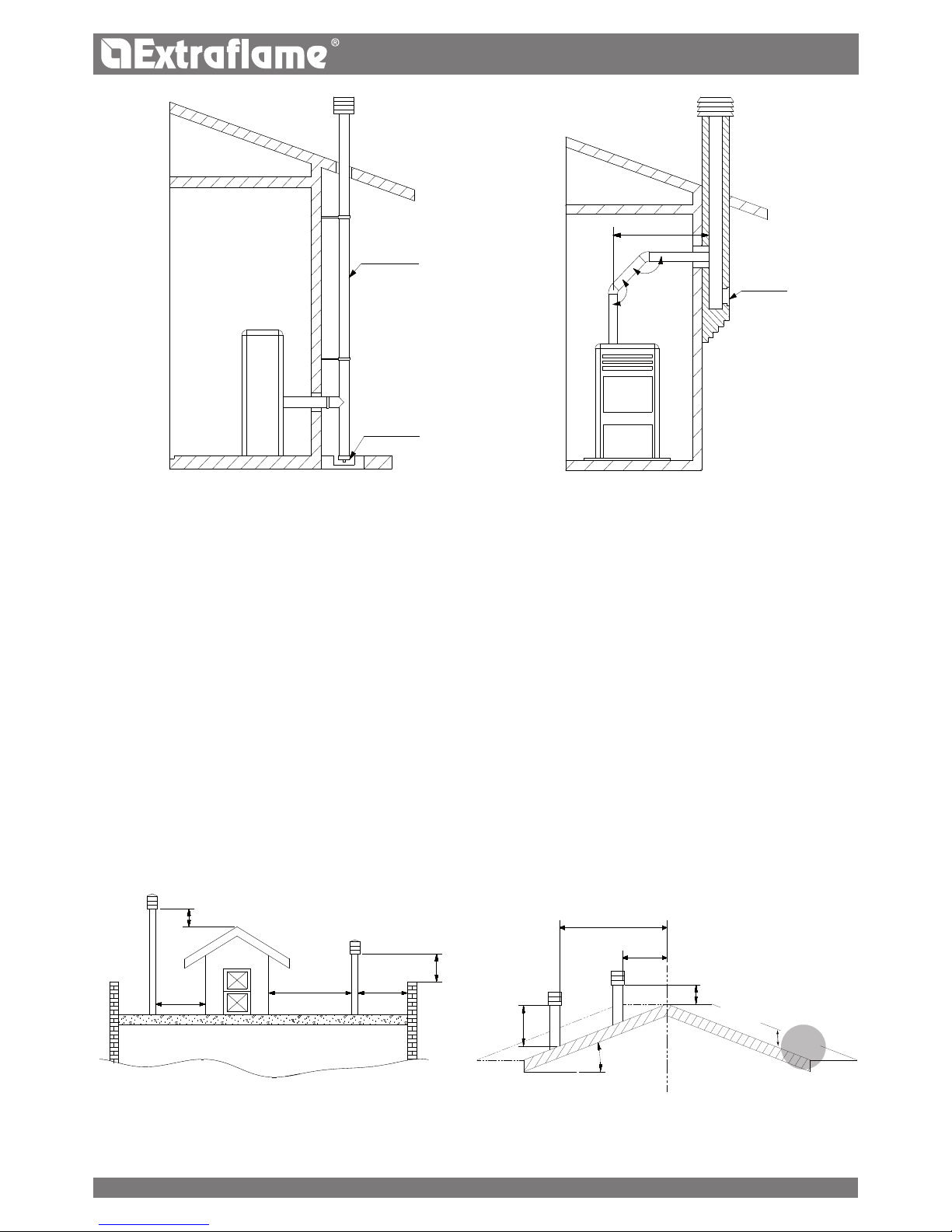
The mounting of horizontal routes must be avoided.
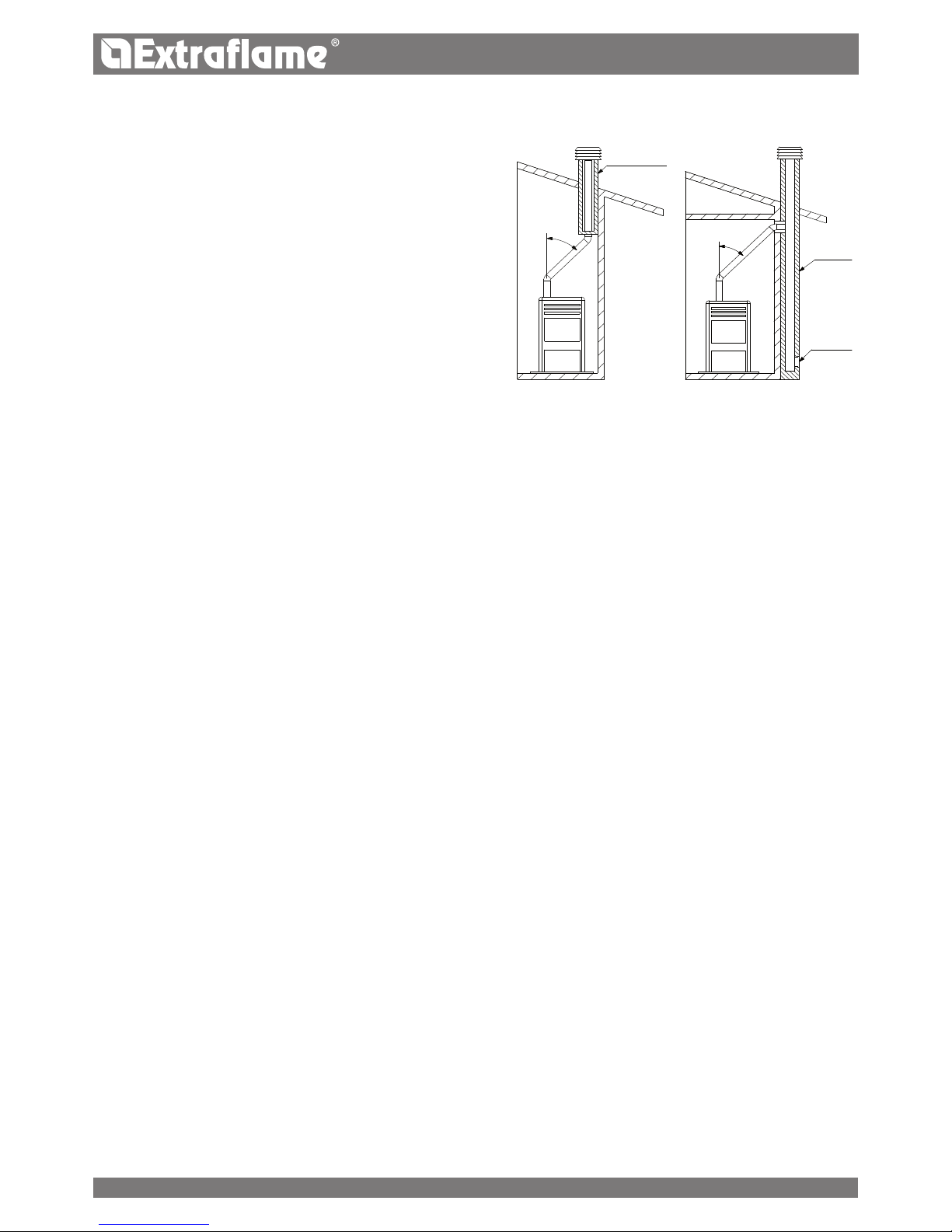
For appliances where ceiling or wall non-coaxial discharges
with respect to the appliance combustion product outlet have
to be reached, the direction changes will have to be realised
using open bends not greater than 45° (see gures below).
For the heat generator appliances equipped with electric fan
for expelling combustion products, the instructions below
must be followed:
45°
<
45°
<
The horizontal routes will have to have a minimum
upward slope of 3%
The length of the horizontal route must be minimal and,
however, not longer than 3 metres
The number of direction changes including the one for
eect of using the "T" element must not be more than 4.
In any case, the smoke channels must seal the combustion and
condensate products and be insulated if they pass outside the
installation room.
The use of counterslope elements is forbidden.
The smoke channel must allow the recovery of soot or be
brushable.
The smoke channel must have constant section. Any section
changes are only allowed at the ue coupling.
It is forbidden to have other air supply channels and pipes for
plant engineering, especially if over-sized, transit inside the
smoke channels. The mounting of manual draught adjustment
devices on forced draught appliances is forbidden.
Insulating
product
Flue
pipe
Inspection
ENGLISH
B
C
A
S
< 3 m
3 - 5 %
7
CHIMNEY OR INDIVIDUAL FLUE
The chimney or individual ue must respond to the following requisites:
seal the combustion products, be waterproof and adequately insulated in line with the use conditions;
be realised with materials which resist the normal mechanical stress, heat, action of the combustion products and any
condensate;
have mainly vertical progress with deviations from the axis not higher than 45°;
be adequately distanced from fuel or ammable materials through air space or opportune insulation;
have preferably circular internal section: the square or rectangular sections must have round corners with a radius not
lower than 20 mm;
have constant internal section, free and independent;
have rectangular section with max. ratio between the sides of 1.5.
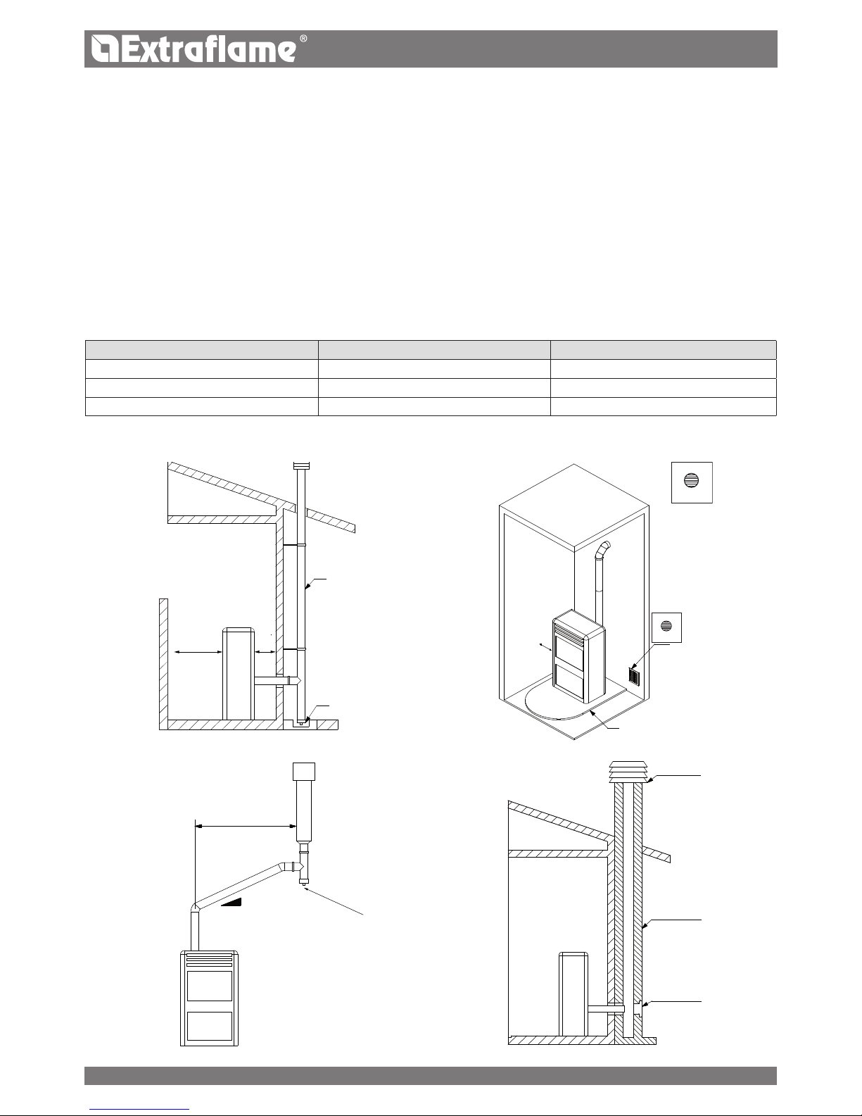
It is recommended that the smoke pipe be equipped with a collection chamber for solid materials and any condensate situated
under the smoke channel inlet, so that it can be easily opened and inspected from airtight door.
REFERENCES INFLAMMABLE OBJECTS NONINFLAMMABLE OBJECTS
A 200 mm 100 mm
B 1,500 mm 750 mm
C 200 mm 100 mm
Minimum 80 cm
2
S= oor protection
Air inlets
Chimney cap
Flue
Inspection
Inspection
Flue
Inspection
ENGLISH
< 3 m
45°
45°
50 cm
< 5 m
> 5 m
< 5 m
50 cm
H min
β
>A
<A
>50 cm
Z
8
External pipe
that is isolated
Inspection
Inspection
Appliance connection to the ue and combustion products evacuation
The ue must receive the discharge from only one heat generator.
Direct discharge towards closed spaces is forbidden, even with clear sky.
The direct discharge of the combustion products must be at roof and the smoke pipe must have the features provided in the
"Chimney or individual ue" section.
CHIMNEY CAP
The chimney cap must comply with the following requisites:
have an internal section equivalent to that of the chimney;
have useful outlet section not lower than double the chimney internal section;
be built in order to avoid rain, snow, foreign bodies penetrating the chimney and so that, in the event of winds in any
direction and inclination, the discharge of the combustion products is assured.
be positioned in a way to guarantee an adequate dispersion and dilution of the combustion products and, however, outside
the reux area in which the formation of counterpressures occurs. Such area has dierent dimensions and conguration
depending on the covering inclination angle. It is therefore necessary to adopt the minimum heights indicated in the gure
layouts below.
The chimney cap must not have mechanical intake means.
FLAT ROOF
SLOPING ROOF
Z=REFLUX AREA
ENGLISH
9
CONNECTION TO EXTERNAL AIR INLETS
The appliance must be able to use the necessary air to guarantee regular functioning through external air inlet. The air inlets
must comply with the following requisites:
have a total free section of at least 80 cm².
must be protected by grates, metal net or suitable protections as long as they do not reduce the minimum section stated
in the previous point and positioned in order to avoid them being obstructed.
If the combustion agent air is withdrawn directly from outside through a pipe, a downward bend must be mounted outside
or a protection against the wind and no grates or similar must be positioned, (it is recommended that the air vent always
communicates directly with the installation room even if the air is withdrawn from outside through a pipe). The air ow can also
be obtained from an adjacent room, as long as the ow takes place freely through permanent openings communicating with
the outside.
The adjacent room, with respect to the installation room, must not be put in depression with respect to the external environment
by means of reverse draught caused by the presence of another used appliance or intake device in such room. The permanent
openings in the adjacent room must comply with the above-described requisites. The adjacent room cannot be set up as garage,
storage for combustion material or activity with danger of re.
INSULATION, FINISHINGS, COVERING AND SAFETY RECOMMENDATIONS
The coverings, independently from the materials from which they are made, must constitute a self-supporting construction
with respect to the heating block and not be in contact with it.
The cross members and nishings in wood or combustion materials must be positioned outside the hearth radiation area or
adequately insulated.
If coverings in combustion material or sensitive to heat exist in the space above the generator, an insulating and non combustible
protection diaphragm must be inserted.
Elements in combustible or inammable material like wooden furniture, curtains, etc. directly exposed to the hearth radiation,
must be positioned at a safe distance. The appliance installation must guarantee easy access for cleaning the appliance itself,
discharge gas pipe and ue.
CHIMNEY CAPS, DISTANCES AND POSITIONING
Roof inclination Distance between the ridge and the chimney Minimum chimney height (measured from outlet)
β A (m) H (m)
15°
< 1,85 0.50 m over the ridge
> 1,85 1,00 m from roof
30°
< 1,50 0.50 m over the ridge
> 1,50 1,30 m from roof
45°
< 1,30 0.50 m over the ridge
> 1,30 2,00 m from roof
60°
< 1,20 0.50 m over the ridge
> 1,20 2.60 m from roof
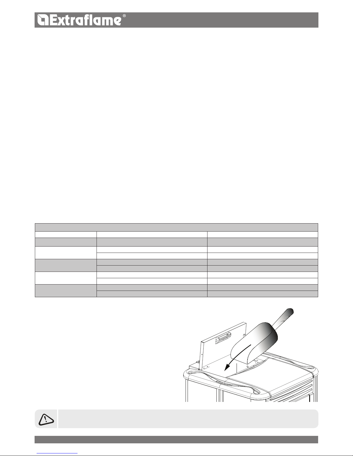
Open the tank lid and load the pellets using a scoop.
PELLETS AND FEEDING
The pellets used must comply with the features described by
the Standard:
Ö-norm M 7135
DIN plus 51731
UNI CEN/TS 14961
Extraame recommends the use of pellets with
a 6 mm diameter for its products.
THE USE OF EXPIRED PELLETS OR ANY OTHER MATERIAL DAMAGES THE FUNCTIONS OF YOUR STOVE AND CAN
DETERMINE THE INVALIDITY OF THE WARRANTY AND THE ANNEXED RESPONSIBILITY OF THE MANUFACTURER.
ENGLISH
 Loading...