


HP 15 22 30
MANUALE UTENTE CALDAIE A PELLET
PELLET STOVES USER MANUAL
MANUEL UTILISATEUR POÊLES À PELLET
BENUTZERHANDBUCH PELLETÖFEN
MANUAL DEL USUARIO ESTUFAS DE PELLET
IT/EN/FR/DE/ES

2

Vi ringraziamo per aver scelto la nostra azienda; il nostro prodotto è un’ottima soluzione di riscaldamento
nata dalla tecnologia più avanzata con una qualità di lavorazione di altissimo livello ed un design sempre
attuale, al ne di farVi godere sempre in assoluta sicurezza la fantastica sensazione che il calore della
amma può darVi.
Nous vous remercions d'avoir choisi notre produit. Notre appareil est une solution de chauage optimale
née de la technologie la plus avancée avec une qualité de fabrication de très haut niveau et un design
toujours actuel, pour vous faire proter – en toute sécurité – de la merveilleuse sensation que procure la
chaleur de la amme.
We thank you for having chosen our company; our product is a great heating solution developed from the
most advanced technology with top quality machining and modern design, aimed at making you enjoy
the fantastic sensation that the heat of a ame gives, in complete safety.
Le agradecemos por haber elegido nuestra empresa; nuestro producto es una óptima solución de
calefacción nacida de la tecnología más avanzada, con una calidad de trabajo de altísimo nivel y un
diseño siempre actual, con el objetivo de hacerle disfrutar siempre, con toda seguridad, la fantástica
sensación que el calor de la llama le puede dar.
Wir danken Ihnen dafür, dass Sie sich für unsere Firma entschieden haben; unser Produkt ist eine ideale
Heizlösung, die auf der neuesten Technologie basiert, sehr hochwertig verarbeitet ist und ein zeitloses
Design aufweist, damit Sie stets in aller Sicherheit das fantastische Gefühl genießen können, das Ihnen die
Wärme der Flamme geben kann

ITALIANO ...................................................................................................................................................................................................................................9
CARATTERISTICHE TECNICHE ......................................................................................................................................................................... 9
IDENTIFICAZIONE DEI COMPONENTI ..............................................................................................................................................................................................10
INTRODUZIONE .............................................................................................................................................................................................. 11
DISTANZE RACCOMANDAT E PER VANO CALDAIA ..................................................................................................................................... 12
AVVERTENZE .................................................................................................................................................................................................. 13
SICUREZZA ..................................................................................................................................................................................................... 13
ORDINARIA MANUTENZIONE ....................................................................................................................................................................... 13
IMPIANTO IDRAULICO ................................................................................................................................................................................... 14
INSTALLAZIONE E DISPOSITIVI DI SICUREZZA .............................................................................................................................................................................14
SICUREZZE PER IMPIANTO A VASO CHIUSO .................................................................................................................................................................................14
DISTANZE DEI DISPOSITIVI DI SICUREZZA SECONDO LA NORMATIVA ..............................................................................................................................14
TIPOLOGIA DI IMPIANTO .............................................................................................................................................................................. 15
IMPIANTO A VASO CHIUSO .................................................................................................................................................................................................................15
VALVOLE DI SICUREZZA ........................................................................................................................................................................................................................15
VASO D’ESPANSIONE CHIUSO .............................................................................................................................................................................................................16
CONTROLLI ALLA PRIMA ACCENSIONE ..........................................................................................................................................................................................16
DISPOSITIVO ANTICONDENSA OBBLIGATORIO ........................................................................................................................................................................16
SCHEMA BASE IMPIANTO IDRAULICO ........................................................................................................................................................17
POSIZIONAMENTO STUFA ....................................................................................................................................................................................................................18
RIARMI ............................................................................................................................................................................................................. 18
CARATTERISTICHE .........................................................................................................................................................................................18
DISPOSITIVI ....................................................................................................................................................................................................19
NORME DI RIFERIMENTO .............................................................................................................................................................................. 19
GENERALITÀ ...............................................................................................................................................................................................................................................20
INSTALLAZIONE .............................................................................................................................................................................................21
INSTALLAZIONE INSERTI .......................................................................................................................................................................................................................21
SISTEMA DI EVACUAZIONE DEI FUMI .......................................................................................................................................................... 22
REQUISITI GENERALI ...............................................................................................................................................................................................................................22
CANALI DA FUMO ....................................................................................................................................................................................................................................23
CAMINO........................................................................................................................................................................................................................................................25
COMIGNOLI ................................................................................................................................................................................................................................................25
REQUISITI DI PRODOTTO PER IL SISTEM
A DI EVACUAZIONE FUMI .....................................................................................................................................26
QUOTA DI SBOCCO DEI PRODOTTI DELLA COMBUSTIONE ....................................................................................................................................................26
DOCUMENTAZIONE TECNICA DELL'INSTALLAZIONE ................................................................................................................................................................27
PELLET E CARICAMENTO .............................................................................................................................................................................. 28
DISP LAY TOUCH SCREEN .............................................................................................................................................................................. 29
QUADRO COMANDI E ICONE ........................................................................................................................................................................ 30
FUNZIONE TASTI ............................................................................................................................................................................................ 31
STRUTTURA MENU ........................................................................................................................................................................................ 31
ISTRUZIONI DI BASE ...............................................................................................................................................................................................................................31
IMPOSTAZ IONI PER LA PRIMA ACCENSIONE .............................................................................................................................................. 32
FREQUENZA DI RETE 50/ 60HZ ...........................................................................................................................................................................................................32
SET OROLOGIO ..........................................................................................................................................................................................................................................32
SET LINGUA .................................................................................................................................................................................................................................................32
FUNZIONAMENTO E LOGICA ...............................................................................................................................................................................................................33
TERMOSTATO AMBIENTE SUPPLEMENTARE .............................................................................................................................................. 34
FUNZIONAMENTO TERMOSTATO AMBIENTE SUPPLEMENTARE CON STBY ATTIVO STBY ON ..............................................................................34
FUNZIONAMENTO TERMOSTATO AMBIENTE SUPPLEMENTARE CON STBY DISATTIVO STBY OFF ......................................................................34
AUX ..................................................................................................................................................................................................................34
SET POTENZA ................................................................................................................................................................................................ 35
SET TEMPERATURE ........................................................................................................................................................................................ 35
SET REGOLAZIONI ......................................................................................................................................................................................... 35
PUL BRACIERE ............................................................................................................................................................................................................................................35
STAND BY .....................................................................................................................................................................................................................................................35
ABILITA CRONO .........................................................................................................................................................................................................................................36
REGOLAZIONE PELLET ...........................................................................................................................................................................................................................36
STATO .............................................................................................................................................................................................................. 36
MENU UTENTE ................................................................................................................................................................................................ 36
CRONO ..........................................................................................................................................................................................................................................................37
LINGUA .........................................................................................................................................................................................................................................................37
DISPLAY ........................................................................................................................................................................................................................................................37
RESET .............................................................................................................................................................................................................................................................38
ALTRE FUNZIONI ............................................................................................................................................................................................ 38
SCARICO ARIA ............................................................................................................................................................................................................................................38
PRIMO CARICO ..........................................................................................................................................................................................................................................38
PULIZIA CAMERA COMBUSTIONE .....................................................................................................................................................................................................38
PRIMO CARICO ..........................................................................................................................................................................................................................................38
PULIZIA E MANUTENZIONE ..............................................................................................................
............................................................ 39
PULIZIA E MANUTENZIONE A CARICO DEL UTENTE .................................................................................................................................................................39
MANUTENZIONE ORDINARIA ......................................................................................................................................................................39
VISUALIZZAZIONI ..........................................................................................................................................................................................43
ALLARMI ......................................................................................................................................................................................................... 43
4

ENGLISH .................................................................................................................................................................................................................................. 45
SPECIFICATIONS ............................................................................................................................................................................................ 45
IDENTIFIC ATION OF COMPONENTS .................................................................................................................................................................................................46
INTRODUCTION ............................................................................................................................................................................................. 47
RECOMMENDED DISTANCES FOR THE BOILER COMPARTMENT .............................................................................................................. 48
WARNINGS ...................................................................................................................................................................................................... 49
SAFETY ............................................................................................................................................................................................................ 49
ROUTINE MAINTENANCE .............................................................................................................................................................................. 49
HYDRAULIC SYSTEM ...................................................................................................................................................................................... 50
INSTALLATION AND SAFETY DEVICES .............................................................................................................................................................................................50
SAFETY DEVICES FOR CLOSED VESSEL SYSTEM ..........................................................................................................................................................................50
DISTANCES OF SAFETY DEVICES ACCORDING TO THE STANDARD .....................................................................................................................................50
TYPE OF SYSTEM ............................................................................................................................................................................................ 51
CLOSED VESSEL PLANT .........................................................................................................................................................................................................................51
SAFETY VALVES .........................................................................................................................................................................................................................................51
CLOSED EXPANSION VESSEL ...............................................................................................................................................................................................................52
COMMISSIONING CHECKS ....................................................................................................................................................................................................................52
AUTOMATIC THERMOSTATIC MIXER VALVE MANDATORY ....................................................................................................................................................52
BASIC HYDRAULIC SYSTEM DIAGRAM ....................................................................................................................................................... 53
STOVE POSITIONING ...............................................................................................................................................................................................................................54
REARMS ........................................................................................................................................................................................................... 54
FEATURES........................................................................................................................................................................................................54
DEVICES .......................................................................................................................................................................................................... 55
REFERENCE STA NDARDS .............................................................................................................................................................................. 55
GENERAL ......................................................................................................................................................................................................................................................56
INSTALLATION ................................................................................................................................................................................................ 57
INSERTS INSTALLATION .........................................................................................................................................................................................................................57
FUMES EXHAUST SYSTEM............................................................................................................................................................................. 58
GENERAL REQUIREMENTS ....................................................................................................................................................................................................................58
SMOKE DUCT .............................................................................................................................................................................................................................................59
CHIMNEY ......................................................................................................................................................................................................................................................61
CHIMNEY CAPS .........................................................................................................................................................................................................................................61
FUMES EXHAUST SYSTEM PRODUCT REQUIREMENTS .............................................................................................................................................................62
COMBUSTION PRODUCTS OUTLET QUOTA ..................................................................................................................................................................................62
TECHNICAL INSTALLATION DOCUMENTATION ...........................................................................................................................................................................63
PELLETS AND FEEDING ................................................................................................................................................................................. 64
TOUCH SCREEN DISP LAY .............................................................................................................................................................................. 65
CONTROL PANEL AN
D ICONS ....................................................................................................................................................................... 66
KEY FUNCTIONS ............................................................................................................................................................................................. 67
MENU STRUCTURE ......................................................................................................................................................................................... 67
BASIC INSTRUCTIONS ............................................................................................................................................................................................................................67
COMMISSIONING SETTINGS ......................................................................................................................................................................... 68
MAINS FREQUENCY 50/ 60HZ .............................................................................................................................................................................................................68
SET CLOCK ...................................................................................................................................................................................................................................................68
SET LANGUAGE .........................................................................................................................................................................................................................................68
OPERATION AND LOGICS .............................................................................................................................................................................. 69
ADDITIONAL ROOM THERMOSTAT .............................................................................................................................................................. 70
ADDITIONAL ROOM THERMOSTAT FUNCTIONING WITH STBY ACTIVE STBY ON ......................................................................................................70
OPERATION OF THE AMBIENT ADDITIONAL THERMOSTAT WITH STBY DISABLED STBY OFF ..............................................................................70
AUX ..................................................................................................................................................................................................................70
SET POWER .................................................................................................................................................................................................... 71
SET TEMPERATURE ........................................................................................................................................................................................ 71
USER REGU LATION ........................................................................................................................................................................................ 71
BURN POT CLEANING .............................................................................................................................................................................................................................71
STAND BY .....................................................................................................................................................................................................................................................71
ENABLE CHRONO .....................................................................................................................................................................................................................................72
PELLET REGULATION ..............................................................................................................................................................................................................................72
STATUS ............................................................................................................................................................................................................ 72
USER MENU..................................................................................................................................................................................................... 72
CHRONO ......................................................................................................................................................................................................................................................73
LANGUAGE ..................................................................................................................................................................................................................................................73
DISPLAY ........................................................................................................................................................................................................................................................73
RESET .............................................................................................................................................................................................................................................................74
OTHER FUNCTIONS ........................................................................................................................................................................................ 74
AIR DISCHARGE .........................................................................................................................................................................................................................................74
FIRST LOAD .................................................................................................................................................................................................................................................74
COMBUSTION CHAMBER CLEANING ...............................................................................................................................................................................................74
FIRST LOAD .................................................................................................................................................................................................................................................74
CLEANING AND MAINTENANCE ................................................................................................................................................................... 75
CLEANING AND MAINTENANCE BY THE USER .............................................................................................................................................................................75
ROUTINE MAINTENANCE ............................................................................................................................................................................. 75
DISPL AYS ........................................................................................................................................................................................................ 79
ALARMS .......................................................................................................................................................................................................... 79
5

FRANÇAIS ............................................................................................................................................................................................................................... 81
CARACTÉRISTIQUES TECHNIQUES .............................................................................................................................................................. 81
IDENTIFIC ATION DES COMPOSANTS ...............................................................................................................................................................................................82
INTRODUCTION ............................................................................................................................................................................................. 83
DISTANCES CONSEILLÉES POUR COMPARTIMENT CHAUDIÈRE .............................................................................................................. 84
MISES EN GARDE ............................................................................................................................................................................................ 85
SÉCURITÉ ........................................................................................................................................................................................................ 85
ENTRETIEN ORDINAIRE ................................................................................................................................................................................. 85
INSTALLATION HYDRAULIQUE ..................................................................................................................................................................... 86
INSTALLATION ET DISPOSITIFS DE SÉCURITÉ ...............................................................................................................................................................................86
DISPOSITIFS DE SÉCURITÉ POUR INSTALLATION À VASE FERMÉ .........................................................................................................................................86
DISTANCES DES DISPOSITIFS DE SÉCURITÉ CONFORMÉMENT À LA NORMATIVE ........................................................................................................86
TYPOLOGIE D'INSTALLATION .......................................................................................................................................................................87
INSTALLATION À VASE FERMÉ ............................................................................................................................................................................................................87
SOUPAPES DE SÉCURITÉ........................................................................................................................................................................................................................87
VASE D'EXPANSION FERMÉ ..................................................................................................................................................................................................................88
CONTRÔLES AU PREMIER ALLUMAGE .............................................................................................................................................................................................88
VANNE MÉLANGEUSE ANTICONDENSATION OBLIG ATOIRE ..............................................................................................................................................88
SCHÉMA DE BASE DE L'INSTALLATION HYDRAULIQUE ............................................................................................................................89
POSITIONNEMENT DU POÊLE .............................................................................................................................................................................................................90
RÉARMEMENTS .............................................................................................................................................................................................. 90
CARACTÉRISTIQUES ...................................................................................................................................................................................... 90
DISPOSITIFS ................................................................................................................................................................................................... 91
NORMES DE RÉFÉRENCE ............................................................................................................................................................................... 91
GÉNÉRALITÉS .............................................................................................................................................................................................................................................92
INSTALLATION ................................................................................................................................................................................................ 93
INSTALLATION DES INSERTS ................................................................................................................................................................................................................93
SYSTÈME D'ÉVACUAT ION DES FUMÉES ....................................................................................................................................................... 94
CONDITIONS GÉNÉRALES .....................................................................................................................................................................................................................94
CANAUX DE FUMÉE .................................................................................................................................................................................................................................95
CHEMINÉE ...................................................................................................................................................................................................................................................97
POTS DE CHEMINÉE .................................................................................................................................................................................................................................97
C
ONDITIONS DES PRODUITS POUR LE SYSTÈME D’ÉVACUAT ION DES FUMÉES ............................................................................................................98
COTE D'EMBOUCHURE DES PRODUITS DE LA COMBUSTION................................................................................................................................................98
DOCUMENTATION TECHNIQUE DE L'INSTALLATION .................................................................................................................................................................99
PELLET ET CHARGEMENT ............................................................................................................................................................................ 100
ÉCRANTACTILE ........................................................................................................................................................................................... 101
TABLEAU DE COMMANDES ET ICÔNES ...................................................................................................................................................... 102
FONCTION DES TOUCHES ...........................................................................................................................................................................103
STRUCTURE MENU ....................................................................................................................................................................................... 103
INSTRUCTIONS DE BASE ...................................................................................................................................................................................................................103
CONFIGURATIONS POUR LE PREMIER ALLUMAGE .................................................................................................................................. 104
FRÉQUENCE DE RÉSEAU 50/60 HZ .................................................................................................................................................................................................104
SET HORLOGE ......................................................................................................................................................................................................................................... 104
SET LANGUE ............................................................................................................................................................................................................................................104
FONCTIONNEMENT ET LOGIQUE ...............................................................................................................................................................105
THERMOSTAT AMBIANT SUPPLÉMENTAIRE ............................................................................................................................................. 106
FONCTIONNEMENT DU THERMOSTAT AMBIANT SUPPLÉMENTAIRE AVEC STBY ACTIVÉ STBY ON ................................................................. 106
FONCTIONNEMENT DU THERMOSTAT AMBIANT SUPPLÉMENTAIRE AVEC STBY DÉSACTIVÉ STBY OFF ....................................................... 106
AUX ................................................................................................................................................................................................................106
SET PUISSANCE ........................................................................................................................................................................................... 107
SET TEMPERATURE ......................................................................................................................................................................................107
REGLAGE UTILISATEUR ............................................................................................................................................................................... 107
NET TOY. BRASIER ................................................................................................................................................................................................................................... 107
STANDBY ................................................................................................................................................................................................................................................. 107
HABILIT. CHRONO .................................................................................................................................................................................................................................108
REGLAGE PELLET ................................................................................................................................................................................................................................... 108
ETAT ............................................................................................................................................................................................................... 108
MENU UTILISATEUR .....................................................................................................................................................................................108
CHRONO ...................................................................................................................................................................................................................................................109
LANGUE .....................................................................................................................................................................................................................................................109
DISPLAY .....................................................................................................................................................................................................................................................109
RESET .......................................................................................................................................................................................................................................................... 110
AUTRES FONCTIONS .................................................................................................................................................................................... 110
EVAC. AIR ..................................................................................................................................................................................................................................................110
CHARGE INITIALE ..................................................................................................................................................................................................................................110
NETTOYAGE CHAMBRE DE COMBUSTION ....
..............................................................................................................................................................................110
CHARGE INITIALE ..................................................................................................................................................................................................................................110
NETTOYAGE ET ENTRETIEN ......................................................................................................................................................................... 111
NETTOYAGE ET ENTRETIEN INCOMBANT À L'UTILISATEUR .................................................................................................................................................111
ENTRETIEN ORDINAIRE ..............................................................................................................................................................................111
VISUALISATIONS .......................................................................................................................................................................................... 115
ALARMES ...................................................................................................................................................................................................... 115
6

DEUTSCH ..............................................................................................................................................................................................................................117
TECHNISCHE EIGENSCHAFTEN ..................................................................................................................................................................117
KENNZEICHNUNG DER BAUTEILE ...................................................................................................................................................................................................118
EINLEITUNG ..................................................................................................................................................................................................119
EMPFOHLENE ABSTÄNDE FÜR DEN HEIZRAUM ....................................................................................................................................... 120
WARNHINWEISE ........................................................................................................................................................................................... 121
SICHERHEIT .................................................................................................................................................................................................. 121
ORDENTLICHE WARTUNG ........................................................................................................................................................................... 121
HYDRAULIKANLAGE .................................................................................................................................................................................... 122
INSTALLATION UND SICHERHEITSVORRICHTUNGEN ............................................................................................................................................................. 122
SICHERHEITSEINRICHTUNGEN FÜR ANLAGE MIT GESCHLOSSENEM AUSDEHNUNGSGEFÄSS ............................................................................ 122
VORSCHRIFTSGEMÄSSE ABSTÄNDE DER SICHERHEITSVORRICHTUNGEN ...................................................................................................................122
ANLAGENART ............................................................................................................................................................................................... 123
ANLAGE MIT GESCHLOSSENEM AUSDEHNUNGSGEFÄSS ................................................................................................................................................... 123
SICHERHEITSVENTILE ..........................................................................................................................................................................................................................123
GESCHLOSSENES AUSDEHNUNGSGEFÄSS ................................................................................................................................................................................. 124
KONTROLLEN BEI DER ERSTMALIGEN ZÜNDUNG ................................................................................................................................................................... 124
AUTOMATISCHES THERMOSTATMISCHVENTIL VERBINDLICH .........................................................................................................................................124
BASISSCHEMA HYDRAULIKANLAGE ........................................................................................................................................................ 125
AUFSTELLUNG DES OFENS ................................................................................................................................................................................................................126
RÜCKSETZUNG .............................................................................................................................................................................................126
EIGENSCHAFTEN .......................................................................................................................................................................................... 126
VORRICHTUNGEN ........................................................................................................................................................................................127
RECHTSVORSCHRIFTEN ..............................................................................................................................................................................127
ALLGEMEINES .........................................................................................................................................................................................................................................128
INSTALLATION .............................................................................................................................................................................................. 129
INSTALLATION VON EINSÄTZEN ......................................................................................................................................................................................................129
RAUCHGASABZUGSANLAGE ...................................................................................................................................................................... 130
ALLGEMEINE ANFORDERUNGEN .................................................................................................................................................................................................... 130
RAUCHGASKANÄLE ..............................................................................................................................................................................................................................131
SCHORNSTEIN ........................................................................................................................................................................................................................................133
SCHORNSTEINKÖPFE ........................................................................................................................................................................................................................... 133
ANFORDERUNGEN AN PRODUKTE FÜR DIE RAUCHGASABZUGSANLAGE ...................................................................................................................134
AUSLASSHÖHE DER VERBRENNUNGSPRODUKTE ................................................................................................................................................................... 134
TECHNISCHE DOKUMENTATION DER INST
ALLATION ............................................................................................................................................................ 135
PELLETS UND PELLETZUFUHR ...................................................................................................................................................................136
TOUCHSCREEN ............................................................................................................................................................................................137
STEUERTAFEL UND SYMBOLE .................................................................................................................................................................... 138
TASTENFUNKTION ....................................................................................................................................................................................... 139
MENÜAUFBAU ..............................................................................................................................................................................................139
GRUNDANWEISUNGEN ......................................................................................................................................................................................................................139
EINSTELLUNGEN FÜR DIE ERSTE INBETRIEBNAHME ............................................................................................................................... 140
NETZFREQUENZ 50/ 60 HZ ................................................................................................................................................................................................................140
SET UHR .....................................................................................................................................................................................................................................................140
SPRACHE EINSTELLEN .........................................................................................................................................................................................................................140
FUNKTIONSWEISE UND LOGIK ................................................................................................................................................................. 141
ZUSÄTZLICHER RAUMTHERMOSTAT .........................................................................................................................................................142
FUNKTIONSWEISE DES ZUSÄTZLICHEN RAUMTHERMOSTAT BEI AKTIVIERTEM STBY STBY ON ....................................................................... 142
FUNKTIONSWEISE DES ZUSÄTZLICHEN RAUMTHERMOSTAT BEI DEAKTIVIERTEM STBY STBY OFF ................................................................142
AUX ................................................................................................................................................................................................................142
SET LEISTUNG .............................................................................................................................................................................................. 143
SET TEMPERATUR ........................................................................................................................................................................................143
USERREGELUNG.......................................................................................................................................................................................... 143
REINIG. BRENNSCHALE .......................................................................................................................................................................................................................143
STAND BY .................................................................................................................................................................................................................................................. 143
FREIGABE CHRONO ..............................................................................................................................................................................................................................144
PELLETREGELUNG ...............................................................................................................................................................................................................................144
STATUS ..........................................................................................................................................................................................................144
BENUTZERMENÜ .......................................................................................................................................................................................... 144
CHRONO ...................................................................................................................................................................................................................................................145
SPRACHE ................................................................................................................................................................................................................................................... 145
DISPLAY ..................................................................................................................................................................................................................................................... 145
RESET .......................................................................................................................................................................................................................................................... 146
SONSTIGE FUNKTIONEN .............................................................................................................................................................................146
LUFTABLASS ............................................................................................................................................................................................................................................146
ERSTE LADUNG ......................................................................................................................................................................................................................................146
REINIGUNG BRENNRAUM ..................................................................................................................................................................................................................146
ERSTE LADUNG ......................................................................................................................................................................................................................................146
REINIGUNG UND WARTUNG ....................................................................................................................................................................... 147
REINIGUNG UND WARTUNG IN VERANTWORTUNG DER NUTZENDEN .......................................................................................................................... 147
ORDENTLICHE WARTUNG ..........................................................................................................................................................................147
ANZEIGEN .....................................................................................................................................................................................................151
AL
ARME ........................................................................................................................................................................................................ 151
7

ESPAÑOL ...............................................................................................................................................................................................................................153
CARACTERÍSTICAS TÉCNICAS .................................................................................................................................................................... 153
IDENTIFICACIÓN DE LOS COMPONENTES .................................................................................................................................................................................. 154
INTRODUCCIÓN ........................................................................................................................................................................................... 155
DISTANCIAS RECOMENDADAS PAR A EL COMPARTIMENTO DE LA CALDERA ...................................................................................... 156
ADVERTENCIAS ............................................................................................................................................................................................157
SEGURIDAD .................................................................................................................................................................................................. 157
MANTENIMIENTO ORDINARIO ...................................................................................................................................................................157
INSTA LACIÓN HIDRÁULICA ........................................................................................................................................................................158
INSTALACIÓN Y DISPOSITIVOS DE SEGURIDAD .......................................................................................................................................................................158
DISPOSITIVOS DE SEGURIDAD PARA LA INSTALACIÓN CON VASO CERRADO ............................................................................................................158
DISTANCIAS DE LOS DISPOSITIVOS DE SEGURIDAD SEGÚN LA NORMATIVA .............................................................................................................. 158
TIPO DE INSTALACIÓN ................................................................................................................................................................................ 159
INSTALACIÓN DE VASO CERRADO ...............................................................................................................................................................................................159
VÁLVULAS DE SEGURIDAD ................................................................................................................................................................................................................159
VASO DE EXPANSIÓN CERRADO .....................................................................................................................................................................................................160
CONTROLES CON EL PRIMER ENCENDIDO ................................................................................................................................................................................. 160
VÁLVULA MEZCLADORA TERMOSTÁTICA OBLIGATORIA ................................................................................................................................................... 160
ESQUEMA BASE INSTAL ACIÓN HIDRÁULICA ........................................................................................................................................... 161
COLOCACIÓN DE LA ESTUFA ............................................................................................................................................................................................................ 162
REARMES ...................................................................................................................................................................................................... 162
CARACTERÍSTICAS ....................................................................................................................................................................................... 162
DISPOSITIVOS .............................................................................................................................................................................................. 163
NORMAS DE REFERENCIA ...........................................................................................................................................................................163
CARACTERÍSTICAS GENERALES ....................................................................................................................................................................................................... 164
INSTA LACIÓN ............................................................................................................................................................................................... 165
INSTALACIÓN INSERTOS..................................................................................................................................................................................................................... 165
SISTEMA DE EVACUACIÓN DE HUMOS ...................................................................................................................................................... 166
REQUISITOS GENERALES ....................................................................................................................................................................................................................166
CANALES DE HUMO ............................................................................................................................................................................................................................. 167
CHIMENEA ................................................................................................................................................................................................................................................ 169
SOMBRERETES ........................................................................................................................................................................................................................................169
REQUISITOS DE LOS PRODUCTOS PARA EL SISTEM
A DE EVACUACIÓN DE HUMOS .................................................................................................170
ALTURA DE SALIDA DE LOS PRODUCTOS DE LA COMBUSTIÓN ........................................................................................................................................170
DOCUMENTACIÓN TÉCNICA DE LA INSTALACIÓN ..................................................................................................................................................................171
PELLET Y CARGA .......................................................................................................................................................................................... 172
PANTALLA TÁCTIL ....................................................................................................................................................................................... 173
CUADRO DE MANDOS E ICONOS ................................................................................................................................................................ 174
FUNCIÓN TECLAS ......................................................................................................................................................................................... 175
ESTRUCTURA DEL MENÚ ............................................................................................................................................................................ 175
INSTRUCCIONES DE BASE .................................................................................................................................................................................................................175
CONFIGURACIONES PARA EL PRIMER ENCENDIDO ................................................................................................................................. 176
FRECUENCIA DE RED 50/ 60HZ ........................................................................................................................................................................................................ 176
SET RELOJ .................................................................................................................................................................................................................................................176
SET IDIOMA .............................................................................................................................................................................................................................................. 176
FUNCIONAMIENTO Y LÓGICA ..................................................................................................................................................................... 177
TERMOSTATO AMBIENTE SUPLEMENTARIO ............................................................................................................................................. 178
FUNCIONAMIENTO DEL TERMOSTATO AMBIENTE SUPLEMENTARIO CON STBY ACTIVADO STBY ON ..........................................................178
FUNCIONAMIENTO DEL TERMOSTATO AMBIENTE SUPLEMENTARIO CON STBY DESACTIVADO STBY OFF.................................................178
AUX ................................................................................................................................................................................................................178
SET POTENCIA ............................................................................................................................................................................................. 179
SET TEMPERATURA ...................................................................................................................................................................................... 179
REGULACIÓN USUARIO ............................................................................................................................................................................... 179
LIMP. BRASERO .......................................................................................................................................................................................................................................179
STAND BY .................................................................................................................................................................................................................................................. 179
HABILIT. CRONO .....................................................................................................................................................................................................................................180
REGULACIÓN PELLET ...........................................................................................................................................................................................................................180
ESTADO .........................................................................................................................................................................................................180
MENÚ DE USUARIO ......................................................................................................................................................................................180
CRONO .......................................................................................................................................................................................................................................................181
IDIOMA ......................................................................................................................................................................................................................................................181
PANTALLA .................................................................................................................................................................................................................................................181
RESET ..........................................................................................................................................................................................................................................................182
OTRAS FUNCIONES ...................................................................................................................................................................................... 182
DESCARGA AIRE ..................................................................................................................................................................................................................................... 182
CARGA INICIAL .......................................................................................................................................................................................................................................182
LIMPIEZA CAMARA DE COMBUSTION .......................................................................................................................................................................................... 182
CARGA INICIAL .......................................................................................................................................................................................................................................182
LIMPIEZA Y MANTEN
IMIENTO.................................................................................................................................................................... 183
LIMPIEZA Y MANTENIMIENTO A CARGO DEL USUARIO ........................................................................................................................................................ 183
MANTENIMIENTO ORDINARIO ..................................................................................................................................................................183
VISUALIZACIONES .......................................................................................................................................................................................187
ALARMAS ...................................................................................................................................................................................................... 187
8
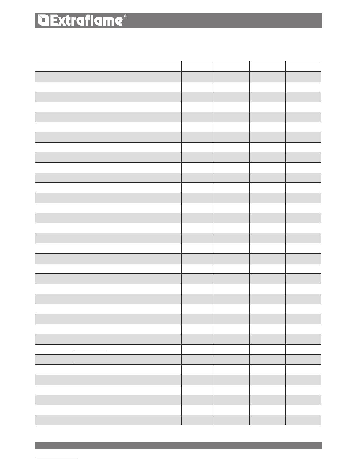
HP 15 HP 22 HP 30
ITALIANO
CARATTERISTICHE TECNICHE
CARATTERISTICHE
Peso kg 250 260 350
Altezza mm 1304 1304 1408
Larghezza mm 560 560 780
Profondità mm 685 785 775
Diametro tubo scarico fumi mm 120 120 120
Diametro tubo aspirazione aria mm 50 50 60
Potenza termica globale max kW 16,9 25 33,9
Potenza termica utile max (resa all’acqua) kW 15,2 22,5 31
Potenza termica globale min kW 5 7,4 9,5
Potenza termica utile min kW 4,4 6,6 8,6
Consumo orario combustibile max kg/h 3,5 5,2 7
Consumo orario combustibile min kg/h 1 1,5 2
Capacità serbatoio pellet kg 43 60 71
Tiraggio del camino consigliato mbar 0,03-0,1 0,03-0,1 0,03-0,1
Potenza elettrica nominale W 450 450 450
Potenza elettrica a Q
MIN W 140 140 160
Potenza elettrica a Q
N W 180 180 200
Potenza in stand By W 3,5 4,0 4,0
Tensione nominale Vac 230 230 230
Frequenza nominale Hz 50 50 50
Diametro tubo entrata/uscita acqua “ 1 1 1
Diametro tubo scarico automatico “ 1/2 1/2 1/2
Prevalenza pompa m 5 5 5
Max pressione idrica di esercizio ammessa bar 2,5 2,5 2,5
Min pressione idrica di esercizio ammessa bar 0,6 0,6 0,6
Temperatura fumi a potenza ridotta °C 56.5 62.7 63
Temperatura fumi a potenza nominale °C 103 136 122
Portata dei fumi potenza ridotta kg/s 0,0055 0,0065 0,0081
Portata dei fumi potenza nominale kg/s 0,0128 0,0164 0,0194
Classe caldaia 5 5 5
Periodo di combustione h 12 12 10
Campo di regolazione termostato acqua °C 65-80 65-80 65-80
Temperatura minima ritorno acqua °C 55 55 55
Rendimento diretto a potenza nominale % >90 >90 91,4
Rumorosità
*
dB 40 40 40
* Valore rilevato in camera anecoica con apparecchio funzionante a potenza nominale.
9
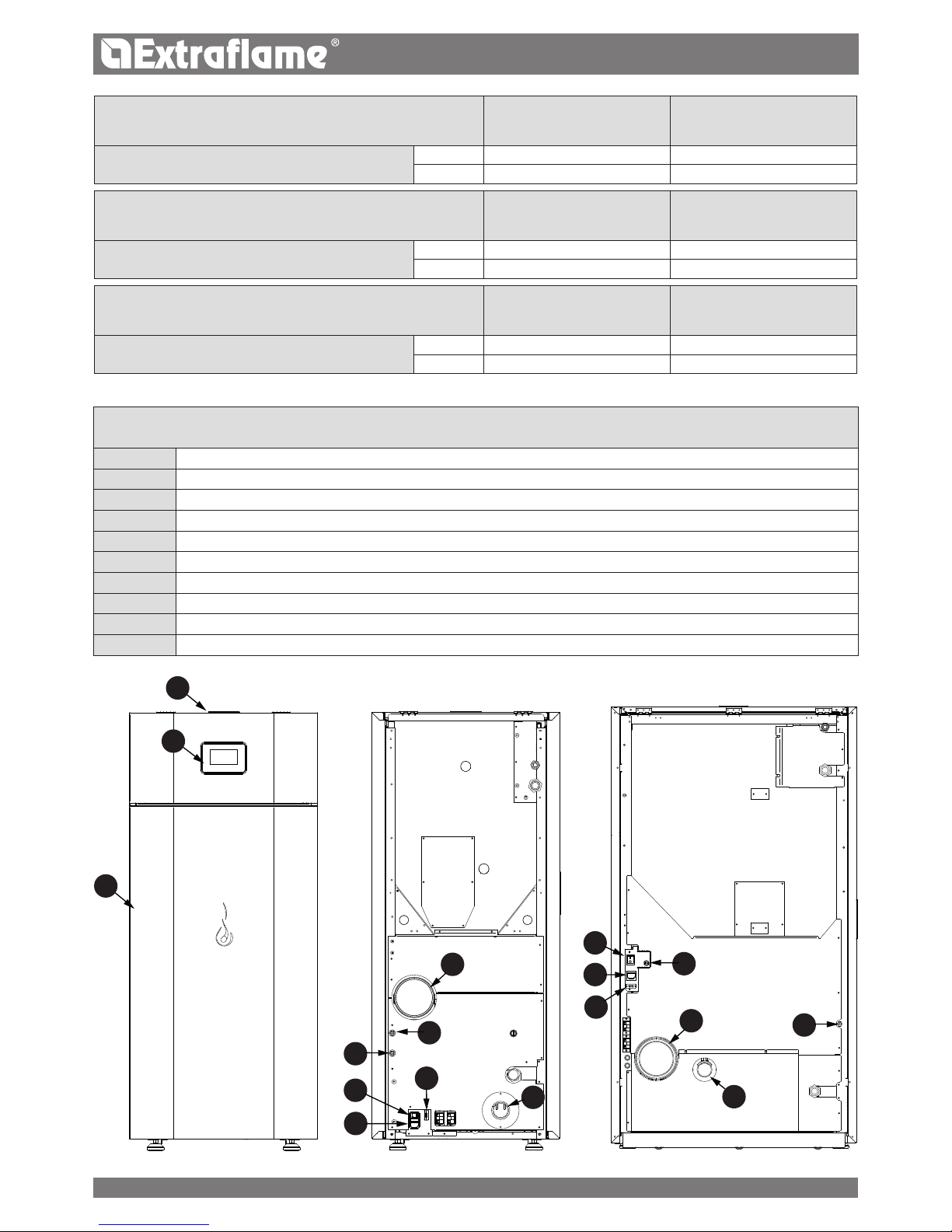
A
B
C
D
D
F
E
F
E
G
G
H
H
I
I
J
J
HP30
HP 15 - 22
ITALIANO
HP 15
FLUSSO D’ACQUA
(kg/h)
RESISTENZA
LATO ACQUA
(mbar)
Salto di temperatura corrispondente
T = 10K 1312 160
T = 20K 656 40
HP 22
FLUSSO D’ACQUA
(kg/h)
RESISTENZA
LATO ACQUA
(mbar)
Salto di temperatura corrispondente
T = 10K 1938 367
T = 20K 969 92
HP 30
FLUSSO D’ACQUA
(kg/h)
RESISTENZA
LATO ACQUA
(mbar)
Salto di temperatura corrispondente
T = 10K 2668 687
T = 20K 1334 172
IDENTIFICAZIONE DEI COMPONENTI
A Display
B Coperchio serbatoio Pellet
C Porta
D Presa alimentazione per cavo elettrico
E Termostato di sicurezza (riarmo manuale) 100°C
F Termostato di sicurezza (riarmo manuale) 85°C
G Tubo scarico fumi di combustione
H Tubo aspirazione aria per la combustione
I Interruttore principale di avviamento
J Porta seriale
10

ITALIANO
INTRODUZIONE
I generatori prodotti nel nostro stabilimento vengono costruiti facendo attenzione anche ai singoli componenti in modo
da proteggere sia l’utente sia l’installatore da eventuali incidenti. Si raccomanda quindi al personale autorizzato, dopo ogni
intervento eettuato sul prodotto, di prestare particolare attenzione ai collegamenti elettrici, soprattutto per quanto riguarda
la parte spellata dei conduttori che non deve uscire in alcun modo dalla morsettiera, evitando così il possibile contatto con le
parti vive del conduttore.
Il presente manuale di istruzione costituisce parte integrante del prodotto: assicurarsi che sia sempre a corredo dell’apparecchio,
anche in caso di cessione ad un altro proprietario o utente oppure di trasferimento su altro luogo. In caso di suo danneggiamento
o smarrimento richiedere un altro esemplare al servizio tecnico di zona.
Questo generatore deve essere destinato all’uso per il quale è stato espressamente realizzato. E’ esclusa qualsiasi responsabilità
contrattuale ed extracontrattuale del costruttore per danni causati a persone, animali o cose, da errori di installazione, di
regolazione di manutenzione e da usi impropri.
INSTALLAZIONE
L’installazione del generatore e degli equipaggiamenti ausiliari, relativi all’impianto di riscaldamento, deve essere conforme a
tutte le norme e regolamentazioni attuali ed a quanto previsto dalla legge. L’installazione deve essere eseguita da personale
autorizzato, che dovrà rilasciare all’acquirente una dichiarazione di conformità dell’impianto, fornire istruzioni necessarie per
l'utilizzo iniziale e si assumerà l’intera responsabilità garantendo il buon funzionamento del prodotto installato.
E’ necessario tenere in considerazione anche tutte le leggi e le normative nazionali, regionali, provinciali e comunali presenti nel
paese in cui è stato installato l’apparecchio.
Non vi sarà responsabilità da parte del fabbricante in caso di mancato rispetto di tali precauzioni. Prima dell’installazione, si
consiglia di eettuare un lavaggio accurato di tutte le tubazioni dell’impianto onde rimuovere eventuali residui che potrebbero
compromettere il buon funzionamento dell’apparecchio. E’ necessario durante l’installazione informare l’utente che:
a. In caso di fuori uscite d’acqua deve chiudere l’alimentazione idrica ed avvisare con sollecitudine il servizio tecnico di assistenza.
b. La pressione di esercizio dell’impianto deve essere periodicamente controllata. In caso di non utilizzo del generatore per un
lungo periodo è consigliabile l’intervento del servizio tecnico di assistenza per eettuare almeno le seguenti operazioni:
- Posizionare l’interruttore generale sulla posizione 0.
- Chiudere i rubinetti dell’acqua sia dell’impianto termico sia del sanitario.
- Svuotare l’impianto termico e sanitario se c’è rischio di gelo.
PRIMA ACCENSIONE
Dopo aver tolto l’imballo, assicurarsi dell’integrità e della completezza del contenuto.
In caso di non rispondenza, rivolgersi al rivenditore da cui è stato acquistato l’apparecchio.
Durante la prima accensione del prodotto è necessario vericare il corretto funzionamento di tutti i dispositivi, sia di sicurezza che
di controllo, che costituiscono il generatore. Tutti i componenti elettrici che costituiscono il generatore, garantendone il corretto
funzionamento, dovranno essere sostituiti con pezzi originali esclusivamente da un centro di assistenza tecnica autorizzato.
Prima di lasciare l’impianto, il personale incaricato alla prima accensione dovrà controllare il funzionamento del generatore
per almeno un ciclo completo di lavoro. La manutenzione del generatore deve essere eseguita almeno una volta all’anno,
programmandola per tempo con il servizio tecnico di assistenza.
NORMATIVE
Le caldaie sono state progettate e realizzate in conformità alle seguenti normative:
UNI EN 303-5 Caldaie per riscaldamento. Caldaie per combustibili solidi, con alimentazione manuale e automatica, con
una potenza termica nominale no a 500 kW
DIRETTIVE
2004/108/CE: direttiva EMC
2006/95/CE: direttiva bassa tensione
2006/42/CE: direttiva macchine
2011/65/EU: direttiva RoHS 2”
PER LA SICUREZZA
E’ vietato l’uso del generatore da parte di bambini o di persone inabili non assistite.
Non toccare il generatore se si è a piedi nudi e con parti del corpo bagnate o umide.
E’ vietato modicare i dispositivi di sicurezza o di regolazione senza l’autorizzazione o le indicazioni del costruttore.
11
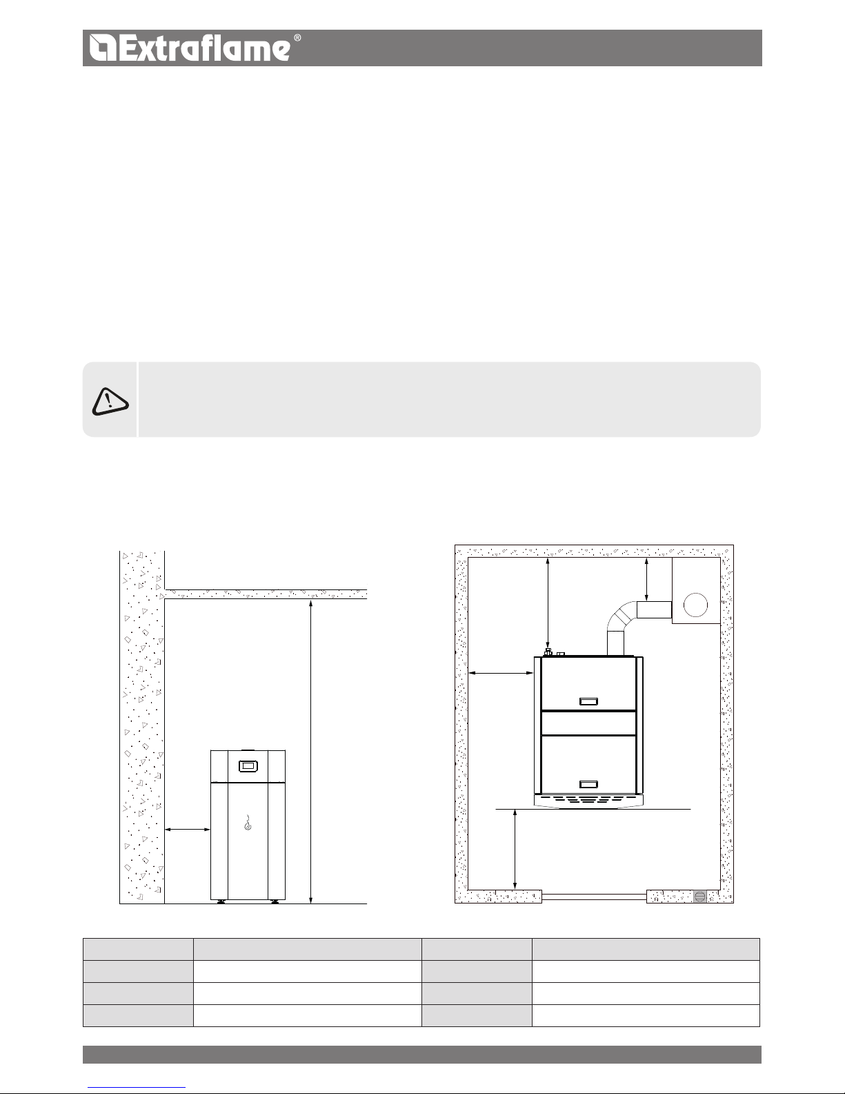
A
F
A
B
D
E
C
ITALIANO
Non tirare, staccare, torcere i cavi elettrici fuoriuscenti dal generatore anche se questa è scollegata dalla rete di alimentazione
elettrica.
Evitare di tappare o ridurre dimensionalmente le aperture di aerazioni del locale di installazione.
Le aperture di aerazione sono indispensabili per una corretta combustione.
Non lasciare gli elementi dell’imballo alla portata dei bambini o di persone inabili non assistite.
Durante il normale funzionamento del prodotto la porta del focolare deve rimanere sempre chiusa.
Evitare il contatto diretto con parti dell’apparecchio che durante il funzionamento tendono a surriscaldarsi.
Controllare la presenza di eventuali ostruzioni prima di accendere l’apparecchio in seguito ad un lungo periodo di mancato
utilizzo.
Il generatore è stato progettato per funzionare con qualsiasi condizione climatica (anche critica), in caso di condizioni
particolarmente avverse (vento forte, gelo) potrebbero intervenire sistemi di sicurezza che portano il generatore in
spegnimento.
Se si verica ciò contattare il servizio di assistenza tecnica e, in ogni caso, non disabilitare i sistemi di sicurezza.
In caso di incendio della canna fumaria munirsi di adeguati sistemi per soocare le amme o richiedere l’intervento dei
vigili del fuoco.
In caso di blocco del generatore evidenziato da segnalazioni sul display e non relativi a mancanza di manutenzione
ordinaria consultare il servizio di assistenza tecnica.
QUESTE CALDAIE DEVONO ESSERE USAT E PER IL RISCALDAMENTO DELL’ACQUA A UNA TEMPERATURA
CHE NON SUPERI QUELLA DI EBOLLIZIONE NELLE CONDIZIONI DI INSTALLAZIONE.
DISTANZE RACCOMANDATE PER VANO CALDAIA
Sotto sono riportate alcune immagini relative alle distanze minime richieste nel locale caldaia.
L'azienda raccomanda di rispettare le misure riportate.
RIFERIMENTI OGGETTI NON INFIAMMABILI RIFERIMENTI OGGETTI NON INFIAMMABILI
A 500 mm D 300 mm
B 1000 mm E > 100 cm
2
C 1000mm F 230cm
12

ITALIANO
AVVERTENZE
Il presente manuale di istruzione costituisce parte integrante del prodotto: assicurarsi che sia sempre a corredo dell’apparecchio,
anche in caso di cessione ad un altro proprietario o utente, oppure di trasferimento su un altro luogo. In caso di suo danneggiamento
o smarrimento richiedere un altro esemplare al servizio tecnico di zona. Questo prodotto deve essere destinato all’uso per il quale
è stato espressamente realizzato. E’ esclusa qualsiasi responsabilità contrattuale ed extracontrattuale del costruttore per danni
causati a persone, animali o cose, da errori d’installazione, di regolazione di manutenzione e da usi impropri.
L’installazione deve essere eseguita da personale qualicato e abilitato, il quale si assumerà l’intera responsabilità
dell’installazione denitiva e del conseguente buon funzionamento del prodotto installato. E’ necessario tenere in
considerazione anche tutte le leggi e le normative nazionali, regionali, provinciali e comunali presente nel paese in cui
è stato installato l’apparecchio, nonché delle istruzioni contenute nel presente manuale.
Non vi sarà responsabilità da parte del fabbricante in caso di mancato rispetto di tali precauzioni.
Dopo aver tolto l’imballo, assicurarsi dell’integrità e della completezza del contenuto. In caso di non rispondenza, rivolgersi al
rivenditore da cui è stato acquistato l’apparecchio.
Tutti i componenti elettrici che costituiscono il prodotto garantendone il corretto funzionamento, dovranno essere sostituiti
con pezzi originali esclusivamente da un centro di assistenza tecnica autorizzato.
SICUREZZA
E’ vietato l’uso del generatore da parte di persone (inclusi bambini) con capacità siche, sensoriali e mentali ridotte, o
inesperte, a meno che non vengano super visionate ed istruite nell’uso dell’apparecchio da una persona responsabile per la
loro sicurezza.
I bambini devono essere controllati per assicurarsi che non giochino con l’apparecchio.
Non toccare il generatore se si è a piedi nudi e con parti del corpo bagnate o umide.
E’ vietato modicare i dispositivi di sicurezza o di regolazione senza l’autorizzazione o le indicazioni del costruttore.
Non tirare, staccare, torcere i cavi elettrici fuoriuscenti dalla stufa anche se questa è scollegata dalla rete di alimentazione
elettrica.
Si raccomanda di posizionare il cavo di alimentazione in modo che non venga in contatto con parti calde dell’apparecchio.
La spina di alimentazione deve risultare accessibile dopo l’installazione.
Evitare di tappare o ridurre dimensionalmente le aperture di aerazione del locale di installazione, le aperture di aerazione
sono indispensabili per una corretta combustione.
Non lasciare gli elementi dell’imballo alla portata dei bambini o di persone inabili non assistite.
Durante il normale funzionamento del prodotto la porta del focolare deve rimanere sempre chiusa.
Quando l'apparecchio è in funzione è caldo al tatto, in particolare tutte le superci esterne, per questo si raccomanda di
prestare attenzione
Controllare la presenza di eventuali ostruzioni prima di accendere l’apparecchio in seguito ad un lungo periodo di mancato
utilizzo.
Il generatore è stato progettato per funzionare con qualsiasi condizione climatica (anche critica), in caso di condizioni
particolarmente avverse (vento forte, gelo) potrebbero intervenire sistemi di sicurezza che portano il generatore in
spegnimento. Se si verica ciò contattare il servizio di assistenza tecnica e, in ogni caso, non disabilitare i sistemi di sicurezza.
In caso di incendio della canna fumaria munirsi di adeguati sistemi per soocare le amme o richiedere l’intervento dei
vigili del fuoco.
Questo apparecchio non deve essere utilizzato come inceneritore di riuti
Non utilizzare alcun liquido inammabile per l’accensione
In fase di riempimento non portare il sacco di pellet a contatto con il prodotto
Le maioliche sono prodotti di alta fattura artigianale e come tali possono presentare micro-puntinature, cavillature ed
imperfezioni cromatiche. Queste caratteristiche ne testimoniano la pregiata natura. Smalto e maiolica, per il loro diverso
coeciente di dilatazione, producono micro screpolature (cavillatura) che ne dimostrano l’eettiva autenticità. Per la pulizia
delle maioliche si consiglia di usare un panno morbido ed asciutto; se si usa un qualsiasi detergente o liquido, quest’ultimo
potrebbe penetrare all’interno dei cavilli evidenziando gli stessi.
ORDINARIA MANUTENZIONE
In base al decreto 22 gennaio 2008 n°37 art.2 per ordinaria manutenzione sono intesi gli interventi nalizzati a contenere il
degrado normale d'uso, nonché a far fronte ad eventi accidentali che comportano la necessità di primi interventi, che comunque
non modicano la struttura dell'impianto su cui si interviene o la sua destinazione d'uso secondo le prescrizioni previste dalla
normativa tecnica vigente e dal libretto di uso e manutenzione del costruttore.
13
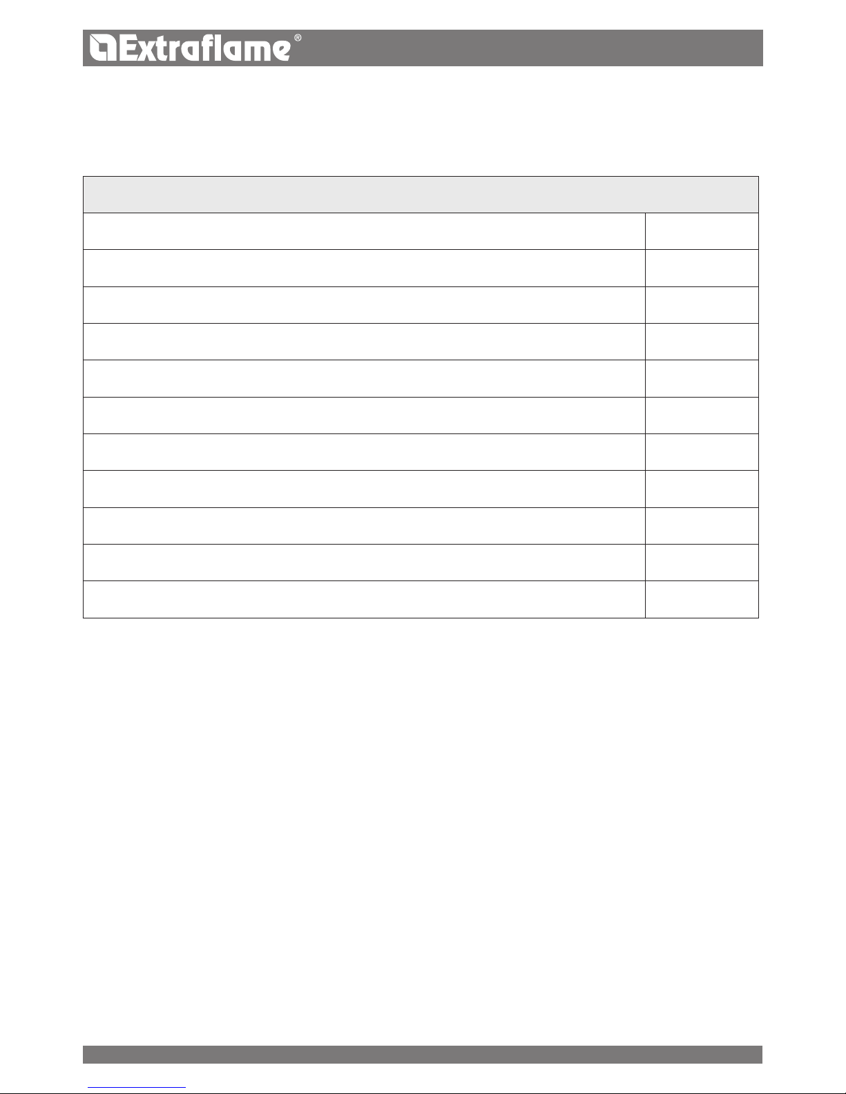
ITALIANO
IMPIANTO IDRAULICO
In questo capitolo sono descritti alcuni concetti che fanno riferimento alla normativa italiana UNI 10412-2 (2009).
Come descritto in precedenza, per l’installazione dovranno essere rispettate tutte le eventuali normative nazionali, regionali,
provinciali e comunali vigenti previste dal paese in cui è stato installato l’apparecchio.
Durante l’installazione del generatore è OBBLIGATORIO adeguare l’impianto con un manometro per la visualizzazione della
pressione dell’acqua.
INSTALLAZIONE E DISPOSITIVI DI SICUREZZA
L’installazione, i relativi collegamenti dell’impianto, la messa in servizio e la verica del corretto funzionamento dovranno essere
eseguiti a regola d’arte, nel pieno rispetto delle normative vigenti, sia nazionali che regionali e comunali, nonché delle presenti
istruzioni.
Per l’Italia, l’installazione deve essere eseguita da personale professionalmente autorizzato (DM 22 gennaio 2008 n^37).
Il Fabbricante declina ogni responsabilità per danni a cose e/o persone provocati dall’impianto.
SICUREZZE PER IMPIANTO A VASO CHIUSO
Secondo la norma UNI 10412-2 (2009) vigente in Italia, gli impianti chiusi devono essere provvisti di: valvola di sicurezza,
termostato di comando del circolatore, termostato di attivazione dell’allarme acustico, indicatore di temperatura, indicatore di
pressione, allarme acustico, interruttore termico automatico di regolazione, interruttore termico automatico di blocco (termostato
di blocco), sistema di circolazione, sistema di espansione, sistema di dissipazione di sicurezza incorporato al generatore con
valvola di scarico termico (auto azionata), qualora l’apparecchiatura non sia provvista di un sistema di autoregolazione della
temperatura.
DISTANZE DEI DISPOSITIVI DI SICUREZZA SECONDO LA NORMATIVA
I sensori di sicurezza della temperatura devono essere a bordo macchina o a una distanza non superiore a 30 cm dal collegamento
di mandata.
TABELLA DEI DISPOSITIVI PER IMPIANTO A VASO CHIUSO PRESENTI E NON PRESENTI NEL PRODOTTO
Valvola di sicurezza
R
Termostato di comando del circolatore (viene gestito dalla sonda acqua e dal programma scheda)
R
Termostato di attivazione dell’allarme acustico
Indicatore di temperatura acqua (display)
R
Trasduttore di pressione con visualizzazione a display
R
Allarme acustico
Interruttore termico automatico di regolazione (gestito dal programma scheda)
R
Trasduttore di pressione con allarme pressostato minima e massima
R
Interruttore termico automatico di blocco (termostato di blocco) sovratemperatura acqua
R
Sistema di circolazione (pompa)
R
Sistema di espansione
R
14

ITALIANO
Qualora i generatori non siano provvisti di tutti i dispositivi, quelli mancanti, possono essere installati sulla tubazione di mandata
del generatore, entro una distanza, dalla macchina, non superiore a 1 m.
COMPONENTE DISTANZA
Sensori di sicurezza della temperatura A bordo macchina o non superiore a 30 cm
Dispositivi mancanti perché non di serie Non superiore a un metro, sul tubo di mandata
Gli apparecchi per riscaldamento di tipo domestico a caricamento automatico devono: essere dotati di un termostato di
blocco del combustibile oppure essere dotati un circuito di rareddamento predisposto dal costruttore dell’apparecchio.
Il circuito di rareddamento deve essere attivato da una valvola di sicurezza termica tale da garantire che non venga superata
la temperatura limite imposta dalla norma.
Il collegamento tra il gruppo di alimentazione e la valvola deve essere privo di intercettazioni.
La pressione a monte del circuito di rareddamento deve essere di almeno 1,5 bar.
TIPOLOGIA DI IMPIANTO
Esistono 2 dierenti tipologie di impianto:
Impianto a vaso aperto e impianto a vaso chiuso.
Il prodotto è stato progettato e realizzato per lavorare con impianti a vaso chiuso.
IMPIANTO A VASO CHIUSO
Impianto in cui l’acqua in esso contenuta non è in comunicazione diretta o indiretta con l’atmosfera. In generale l’impianto a
vaso chiuso è dotato di uno dei seguenti dispositivi di espansione:
Vaso d’espansione chiuso precaricato, con membrana impermeabile al passaggio dei gas.
Sistema d’espansione chiuso automatico con compressore e membrana impermeabile al passaggio dei gas.
Sistema d’espansione chiuso automatico, con pompa di trasferimento e membrana impermeabile al passaggio dei gas.
Sistema di espansione senza diaframma.
GENERALITÀ
Gli impianti chiusi devono essere provvisti di:
Valvola di sicurezza
Termostato di comando del circolatore
Termostato di attivazione dell’allarme acustico
Indicatore di temperatura
Indicatore di pressione
Allarme acustico
Interruttore termico automatico di regolazione
Interruttore termico automatico di blocco (termostato di blocco)
Sistema di circolazione
Sistema di espansione
Sistema di dissipazione di sicurezza incorporato al generatore con valvola di scarico termico (auto azionata), qualora
l’apparecchiatura non sia provvista di un sistema di autoregolazione della temperatura
VALVOLE DI SICUREZZA
La portata di scarico della valvola di sicurezza deve essere tale da consentire lo scarico di un quantitativo di vapore, non inferiore
a: Q / 0,58 [kg/h] dove: Q è la potenza utile resa all’acqua del generatore espressa in kilowatt. Il diametro della minima sezione
trasversale netta dell’entrata della valvola deve comunque essere non minore di 15 mm. La pressione di scarico della valvola, pari
alla pressione di taratura, aumentata della sovrapressione, non può superare la pressione massima di esercizio del generatore di
calore. Il progettista deve vericare che la pressione massima esistente in ogni punto dell’impianto non superi quella massima
di esercizio di ogni suo componente. La valvola di sicurezza deve essere collegata alla parte più alta del generatore di calore o
alla tubazione di uscita, nelle immediate vicinanze del generatore. La lunghezza del tratto di tubazione compreso tra l’attacco
al generatore e la valvola di sicurezza non deve comunque essere maggiore di 1 m. La tubazione di collegamento della valvola
15
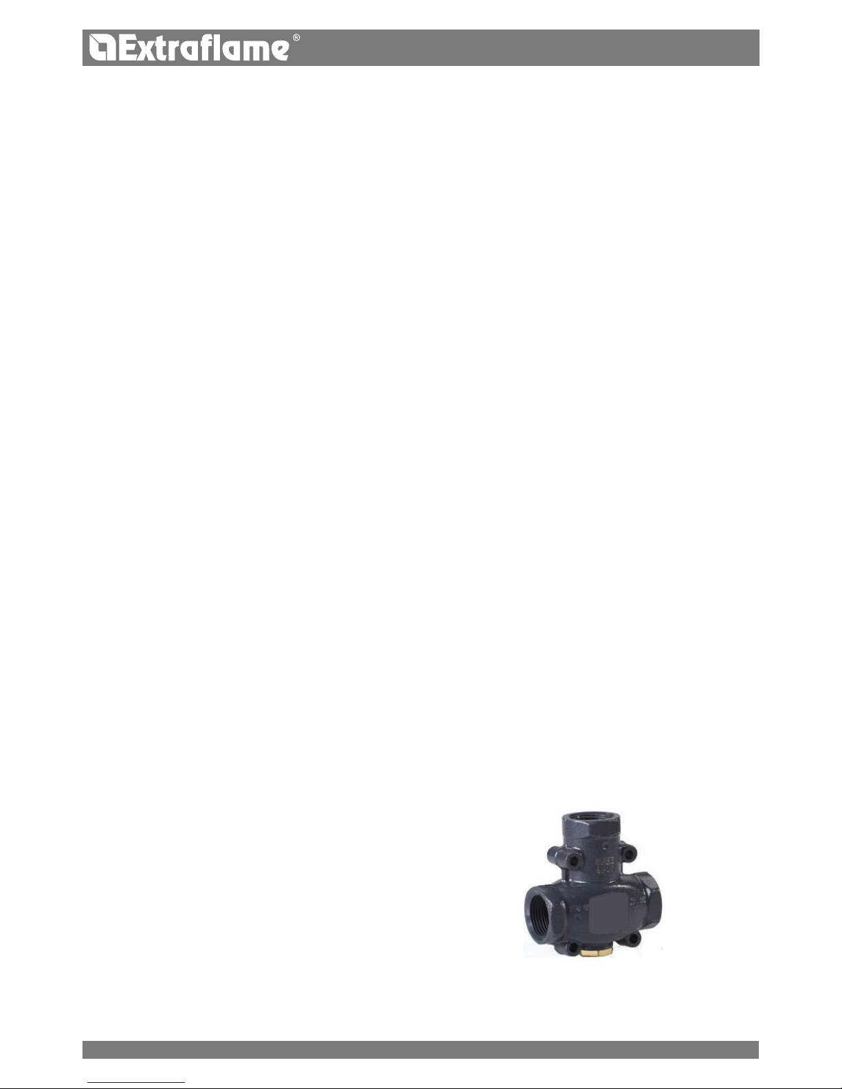
1
2
3
ITALIANO
di sicurezza al generatore di calore non deve essere intercettabile e non deve presentare, in nessun punto, sezione inferiore
a quella di ingresso della valvola di sicurezza o alla somma delle sezioni di ingresso nel caso di più valvole facenti capo ad
un’unica tubazione. La tubazione di scarico della valvola di sicurezza deve essere realizzata in modo da non impedire la regolare
funzionalità delle valvole e da non arrecare danno alle persone; lo scarico deve sboccare nelle immediate vicinanze della valvola
di sicurezza ed essere accessibile e visibile. Il diametro della tubazione di scarico non deve comunque essere inferiore a quello
del raccordo di uscita della valvola di sicurezza. Quale diametro del raccordo di uscita va inteso il diametro interno minimo
sull’uscita della valvola a monte dell’eventuale lettatura interna.
VASO D’ESPANSIONE CHIUSO
Avvertenze: vericare che la precarica del vaso di espansione sia ad una pressione di 1.5 bar.
La pressione massima di esercizio del vaso deve essere non inferiore alla pressione di taratura della valvola di sicurezza,
aumentata dalla sovrapressioni caratteristica della valvola stessa, tenuto conto dell’eventuale dislivello tra vaso e valvola e della
pressione generata dal funzionamento della pompa. La capacità del o dei vasi d’espansione è valutata in base alla capacità
complessiva dell’impianto quale risulta dal progetto. I vasi di espansione chiusi devono essere conformi alle disposizioni per gli
apparecchi a pressione in materia di progettazione, fabbricazione, valutazione di conformità ed utilizzazione. Sulla tubazione di
collegamento, che può essere costituita da porzioni d’impianto, non devono essere inseriti organi di intercettazione né praticate
diminuzioni di sezione. E’ consentito l’inserimento di una valvola di intercettazione a tre vie che permetta il collegamento del
vaso con l’atmosfera, per operazioni di manutenzione. Tale dispositivo deve essere protetto contro le manovre accidentali. Il
tubo di collegamento deve essere realizzato in modo da non presentare punti di accumulo di incrostazioni o depositi. Nel caso
di più generatori di calore che alimentano uno stesso impianto o uno stesso circuito secondario, ciascun generatore di calore
deve essere collegato direttamente al vaso di espansione o al gruppo dei vasi di espansione dell’impianto complessivamente
dimensionati per il volume totale dell’acqua contenuta nello stesso impianto e nello stesso circuito indipendente. Ove si renda
necessario separare il singolo generatore di calore dal vaso di espansione o dal gruppo di vasi di espansione, si deve ricorrere,
sulla tubazione di collegamento del generatore al vaso, ad un rubinetto a tre vie con le stesse caratteristiche elencate sopra, in
modo da assicurare comunque, in ogni posizione, il collegamento del generatore o con il vaso di espansione o con l’atmosfera.
I vasi di espansione, le tubazioni di collegamento, i tubi di sato e di scarico devono essere protetti dal gelo ove tale fenomeno
possa vericarsi. La soluzione adottata a tal ne deve essere descritta nel progetto.
CONTROLLI ALLA PRIMA ACCENSIONE
Prima di allacciare la caldaia prevedere:
a) un lavaggio accurato di tutte le tubazioni dell’impianto onde rimuovere eventuali residui che potrebbero compromettere il
buon funzionamento di qualche componente dell’impianto (pompe, valvole, ecc.).
b) un controllo per vericare che il camino abbia un tiraggio adeguato, non presenti strozzature e che non siano inseriti nella
canna fumaria scarichi di altri apparecchi.
Questo per evitare aumenti di potenza non previsti. Solo dopo questo controllo può essere montato il raccordo camino fra
caldaia e canna fumaria. Si consiglia un controllo dei raccordi con canne fumarie preesistenti.
DISPOSITIVO ANTICONDENSA OBBLIGATORIO
E' obbligatorio realizzare un adeguato circuito di anticondensa, che garantisca una temperatura di ritorno dell’apparecchio di
almeno 55°C . La valvola anticondensa, ad esempio, trova applicazione nelle caldaie a combustibile solido in quanto previene il
ritorno di acqua fredda nello scambiatore.
Le tratte 1 e 3 sono sempre aperte e, assieme alla pompa
installata sul ritorno, garantiscono la circolazione dell’acqua
all’interno dello scambiatore del generatore.
Una elevata temperatura di ritorno permette di migliorare
l’ecienza, riduce la formazione di condensa dei fumi e
allunga la vita del generatore .
Le valvole in commercio presentano svariate tarature,
Il fabbricante consiglia l’utilizzo del modello 55°C con
connessioni idrauliche da 1’’.
Una volta raggiunta la temperatura di taratura della
valvola, viene aperta la tratta 2 e l’acqua della caldaia va
all’impianto attraverso la mandata.
Valvola in vendita come accessorio (opzione)
16
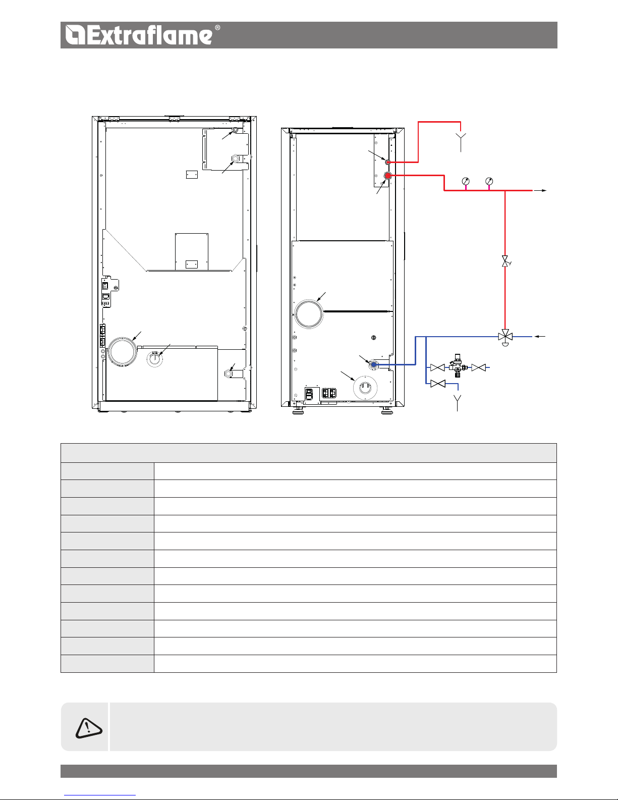
T1
T2
T3
B
A
T1
T2
B
T3
A
1 2
3
SI
T
M
S
G
VB
VMTA
HP 30
HP 15/22
ITALIANO
SCHEMA BASE IMPIANTO IDRAULICO
LEGENDA
A Entrata aria comburente
B Uscita scarico fumi
T1 Scarico valvola sicurezza 3 bar
T2 Mandata / uscita caldaia
T3 Ritorno / ingresso caldaia
M Manometro
T Termometro
G Gruppo di riempimento
S Scarico valvola di sicurezza
SI Scarico impianto
VB Valvola di bilanciamento
VMTA Valvola miscelatrice termostatica 55°C
SI RACCOMANDA DI CONSULTARE IL MANUALE DIME PRESENTE NEL SITO PER MAGGIORI INFORMAZIONI
RELATIVE AI COLLEGAMENTI IDRAULICI, ASPIRAZIONE ARIA/ SCARICO FUMI E SPECIFICHE DIMENSIONI DEL
PRODOTTO INTERESSATO.
17
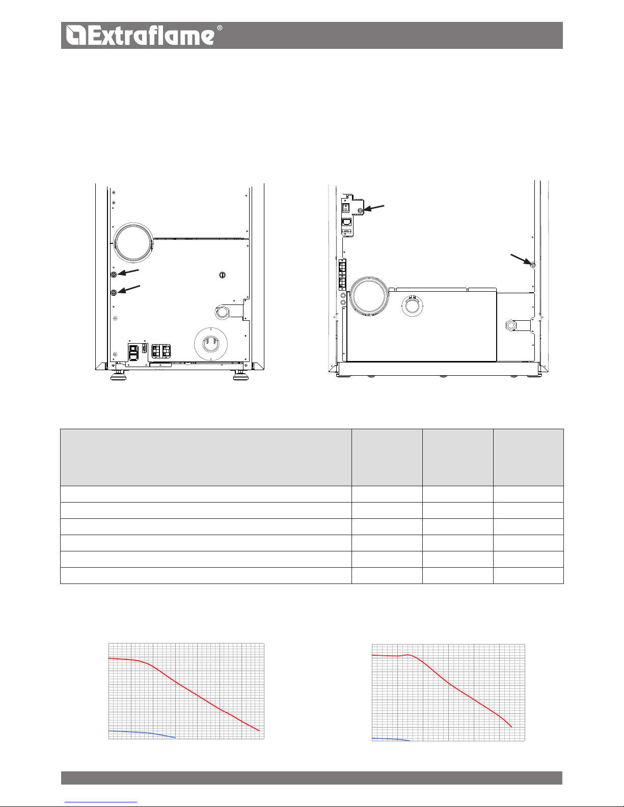
H
0
1
2
3
4
5
6
7
0 0,5 1 1,5 2 2,5 3
85°C
100°C
H
85°C
100°C
HP 30
HP15 - 22
0
1
2
3
4
5
6
7
0 0,5 1 1,5 2 2,5 3 3,5
HP15
HP22-30
ITALIANO
POSIZIONAMENTO STUFA
Per un corretto funzionamento del prodotto si raccomanda di posizionarlo in modo che sia perfettamente in piano, con l’ausilio
di una livella.
Il graco riportato a lato illustra il comportamento del circolatore utilizzato nei nostri termoprodotti alle velocità impostabili.
Portata (m
3
/h)
Prevalnza (m)
CARATTERISTICHE
HP 15 HP22 HP 30
Contenuto d’acqua scambiatore (l) del termoprodotto 32 32 66
Volume vaso espansione integrato nel termoprodotto (l) 8 8 12
Valvola sicurezza 3 bar integrata nel termoprodotto
P P P
Pressostato di minima e massima integrato nel termoprodotto
P P P
Circolatore integrato nel termoprodotto
P P P
Prevalenza max circolatore (m) 6 6 6
* PREVEDERE EVENTUALE VASO DI ESPANSIONE INTEGRATIVO IN BASE AL CONTENUTO D'ACQUA DELL'IMPIANTO.
RIARMI
Nelle gure sottostanti sono ragurati le posizioni dei riami del serbatoio (85°C) e H2O (100°C). Si raccomanda di contattare il
tecnico abilitato qualora dovesse scattare uno dei riarmi, per vericarne la causa.
Portata (m
3
/h)
Prevalnza (m)
18
ITALIANO
DISPOSITIVI
(nei modelli previsti)
Micro porta: Con la porta aperta viene bloccato il
funzionamento del sistema di pulizia del braciere
Pressostato elettronico: in caso di pressione inadeguata porta
la macchina in allarme
Fusibile F 2.5 A 250 V (stufe): protegge la macchina da sbalzi
di corrente violenti
Bulbo meccanico tarato 85°C a riarmo manuale: interviene
bloccando il carico di combustibile qualora la t° del serbatoio
del pellet raggiunga il limite di 85°C. Il riarmo deve essere
eseguito da personale qualicato e/o assistenza tecnica del
costruttore
Sonda controllo temperatura serbatoio pellet: in caso
di surriscaldamento del serbatoio la macchina modula in
automatico per ritornare ai valori di temperatura normali
Pressostato meccanico aria: blocca il pellet in caso di
depressione insuciente.
NORME DI RIFERIMENTO
L’installazione deve essere conforme a:
UNI 10683 (2012) generatori di calore alimentati a
legna o altri combustibili solidi: installazione.
I camini devono essere conformi a:
UNI EN 13063-1 e UNI EN 13063-2, UNI EN 1457, UNI EN
1806 nel caso di camini non metallici:
UNI EN 13384 metodo di calcolo delle caratteristiche
termiche e uido-dinamiche dei camini.
UNI EN 1443 (2005) camini: requisiti generali.
UNI EN 1457 (2012) camini: condotti interni di terracotta
e ceramica.
UNI/TS 11278 (2008) Camini/ canali da fumo/condotti/
canne fumarie metallici.
UNI 7129 punto 4.3.3 disposizioni, regole locali e
prescrizioni dei VVFF.
REGOLAMENTAZIONI NAZIONALI,
REGIONALI,PROVINCIALI E COMUNALI
E’ necessario tenere in considerazione anche tutte le leggi e le
normative nazionali, regionali, provinciali e comunali presenti
nel paese in cui è stato installato l’apparecchio
TERMINI E DEFINIZIONI
Aerazione: Ricambio dell'aria necessaria sia per lo smaltimento
dei prodotti della combustione, sia per evitare miscele con un
tenore pericoloso di gas non combusti.
Apparecchio a focolare chiuso: Apparecchio previsto per il
funzionamento con camera di combustione chiusa.
Apparecchio a tiraggio forzato: Apparecchio dotato di
ventilazione nel circuito fumi e di combustione con mandata
dei fumi con una pressione positiva rispetto all'ambiente.
Camino: Struttura consistente di una o più pareti contenente
una o più vie di eusso.
Tale elemento ad andamento prevalentemente verticale ha lo
scopo di espellere a conveniente altezza dal
suolo i prodotti della combustione.
Canale da fumo: Componente o componenti che raccordano
l'uscita del generatore di calore al camino.
Comignolo: Dispositivo che posto alla bocca del camino
permette la dispersione dei prodotti della combustione anche
in presenza di avverse condizioni atmosferiche.
Condensa: Prodotti liquidi che si formano quando la
temperatura dei fumi è minore o uguale al punto di rugiada
dell'acqua.
Condotto per intubamento: Condotto composto da
uno o più elementi a sviluppo prevalentemente verticale
specicatamente adatto a raccogliere ed espellere i fumi,
nonché a resistere nel tempo ai componenti degli stessi e
delle loro eventuali condense,
idoneo per essere inserito in un camino, vano tecnico esistente
o di nuova costruzione, anche in nuovi edici.
Installazione stagna: Installazione di un apparecchio a
funzionamento stagno in modo che tutta l'aria necessaria per
la combustione sia prelevata dall'esterno.
Manutenzione: Insieme degli interventi necessari per
garantire nel tempo la sicurezza e la funzionalità e conservare
l'ecienza dell'impianto entro i parametri prescritti.
Sistema camino: Camino installato utilizzando una
combinazione di componenti compatibili, fabbricati o
specicati da un solo fabbricante la cui responsabilità di
prodotto riguarda l'intero camino.
Sistema di evacuazione fumi: Impianto per l'evacuazione
dei fumi indipendente dall'apparecchio costituito da canale
da fumo, camino, torrino ed eventuale comignolo.
Zona di irraggiamento: Zona immediatamente adiacente
al focolare in cui si dionde il calore radiante provocato dalla
combustione.
Zona di reusso: Zona oltre l'estradosso del tetto in cui
si vericano sovrappressioni o depressioni che possono
inuenzare la corretta evacuazione dei prodotti della
combustione.
19

ITALIANO
SCHEMA FUNZIONALE DELLE OPERAZIONI
L'esecuzione a regola d'arte e il corretto esercizio dell'impianto comprendono una serie di operazioni:
1. Attività preliminari:
Vericare l'idoneità della potenza del generatore di calore in base alle caratteristiche dell'impianto;
verica dell' idoneità del locale di installazione,
verica dell' idoneità del sistema di evacuazione fumi,
verica dell'idoneità delle prese d'aria esterna;
2. Installazione:
realizzazione della ventilazione e collegamento alle prese d'aria esterne,
realizzazione e collegamento al sistema di evacuazione fumi,
montaggio e posa in opera,
eventuali collegamenti elettrici ed idraulici,
posa di coibentazione,
prova di accensione e di funzionalità,
posa di niture e rivestimenti;
3. Rilascio della documentazione complementare;
4. Controllo e manutenzione.
Altri adempimenti possono essere richiesti in relazione a speciche richieste dell'Autorità competente.
ATTIVITÀ PRELIMINARI
GENERALITÀ
La verica di compatibilità dell'impianto, delle eventuali limitazioni disposte da regolamenti amministrativi locali, prescrizioni
particolari o convenzionali derivanti da regolamento di condominio, servitù o leggi o atti amministrativi, deve precedere ogni
altra operazione di montaggio o posa in opera.
In particolare deve essere vericata l'idoneità:
dei locali d'installazione, la presenza nei locali di installazione ed in quelli adiacenti e comunicanti di apparecchi già
installati, anche alimentati con combustibili diversi, con particolare riferimento alle installazioni non ammesse.
del sistema di evacuazione fumi
delle prese d'aria esterne
IDONEITÀ DEL SISTEMA DI EVACUAZIONE FUMI
L'installazione deve essere preceduta da una verica di compatibilità tra l'apparecchio e il sistema di evacuazione fumi attraverso
la verica di:
esistenza della documentazione relativa all'impianto;
esistenza e contenuto della placca camino;
adeguatezza della sezione interna del camino;
assenza di ostruzioni lungo tutto il camino;
altezza e sviluppo prevalentemente verticale del camino;
esistenza e idoneità del comignolo;
distanza della parete esterna del camino e del canale da fumo dai materiali
combustibili;
tipo e materiale del camino;
assenza di altri allacciamenti al camino.
20

B
C
A
S
ITALIANO
INSTALLAZIONE
E' vietata l'installazione all'interno di locali con pericolo incendio. E' inoltre vietata l'installazione all'interno di locali ad uso
abitativo (ad eccezione degli apparecchi del tipo a funzionamento stagno):
nei quali siano presenti apparecchi a combustibile liquido con funzionamento continuo o discontinuo che prelevano l'aria
comburente nel locale in cui sono installati, oppure
nei quali siano presenti apparecchi a gas di tipo B destinato al riscaldamento degli ambienti, con o senza produzione di
acqua calda sanitaria e in locali ad essi adiacenti e comunicanti, oppure
nei quali comunque la depressione misurata in opera fra ambiente esterno e interno sia maggiore a 4 Pa
Installazioni in bagni, camere da letto e monolocali
In bagni, camere da letto e monolocali è consentita esclusivamente l'installazione stagna o di apparecchi a focolare chiuso con
prelievo canalizzato dell'aria comburente dall'esterno.
Requisiti del locale di installazione
l piani di appoggio e/o punti di sostegno devono avere una capacità portante idonea a sopportare il peso complessivo
dell'apparecchio, degli accessori e dei rivestimenti del medesimo. Le pareti adiacenti laterali e posteriori e il piano di appoggio a
pavimento devono essere realizzate in materiale non combustibile . E' ammessa l'installazione in adiacenza a materiali combustibili
o sensibili al calore purché sia interposta idonea distanza di sicurezza, che per le stufe a pellet è pari a:
RIFERIMENTI OGGETTI INFIAMMABILI OGGETTI NON INFIAMMABILI
A 200 mm 100 mm
B 1500 mm 750 mm
C 200 mm 100 mm
In ogni caso la temperatura dei materiali combustibili adiacenti non deve raggiungere una temperatura uguale o maggiore
della temperatura ambiente aumentata di 65 °C.
Il volume minimo del locale in cui installare l'apparecchio deve essere maggiore di 15 m³.
INSTALLAZIONE INSERTI
Nel caso di installazione d'inserti, deve essere impedito l'accesso alle parti interne dell'apparecchio, e durante l'estrazione non
deve essere possibile accedere alle parti sotto tensione.
Eventuali cablaggi come ad esempio cavo di alimentazione o sonde ambiente devono essere posizionati in modo da non
rimanere danneggiati durante il movimento dell'inserto o venire a contatto con parti calde.
Presa d'aria
S= salva pavimento
Canna fumaria
Ispezione
gura 1 gura 2
21
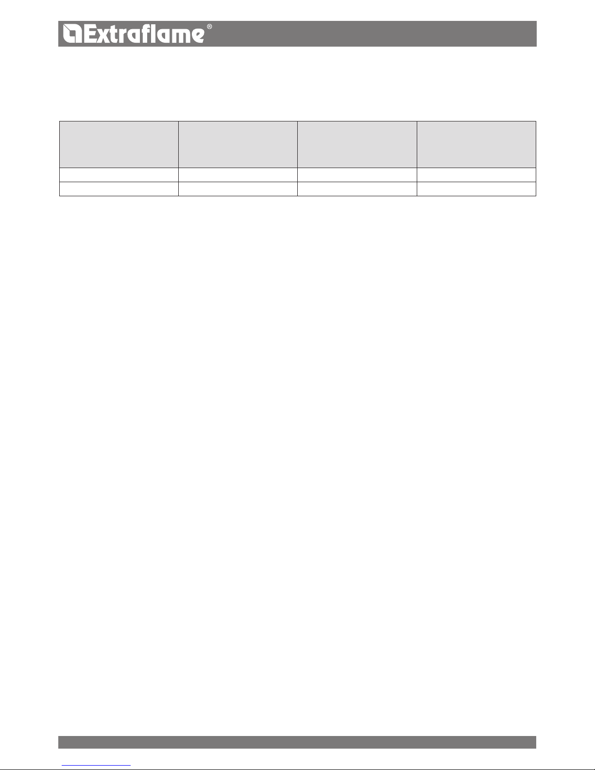
ITALIANO
VENTILAZIONE ED AERAZIONE DEI LOCALI DI INSTALLAZIONE
La ventilazione si ritiene suciente quando il locale è provvisto di prese d'aria in base alla tabella:
Prese d'aria
Vedi gura 2
Categorie di apparecchi Norma di riferimento
Percentuale della sezione
netta di apertura rispetto
alla sezione di uscita fumi
dell'apparecchio
Valore minimo netto di
apertura condotto di
ventilazione
Stufe a pellet UNI EN 14785 - 80 cm²
Caldaie UNI EN 303-5 50% 100 cm²
In ogni caso la ventilazione si ritiene suciente, quando la dierenza di pressione fra ambiente esterno ed interno risulta uguale
o minore di 4 Pa.
In presenza di apparecchi a gas di tipo B a funzionamento intermittente non destinati al riscaldamento deve essere ad essi
dedicata un'apertura di aerazione e/o ventilazione. Le prese d'aria devono soddisfare i requisiti seguenti:
essere protette mediante griglie, reti metalliche, ecc., senza ridurne, peraltro, la sezione utile netta;
essere realizzate in modo da rendere possibili le operazioni di manutenzione;
posizionate in maniera tale da non poter essere ostruite;
L'ausso dell'aria pulita e non contaminata può essere ottenuto anche da un locale adiacente a quello di installazione ( aereazione
e ventilazione indiretta) purché tale usso possa avvenire liberamente attraverso aperture permanenti comunicanti con l'esterno.
Il locale adiacente non può essere adibito ad autorimessa, magazzino di materiale combustibile né comunque ad attività con
pericolo incendio, bagno, camera da letto o locale comune dell' immobile.
SISTEMA DI EVACUAZIONE DEI FUMI
REQUISITI GENERALI
Il generatore di calore lavora in depressione ed è dotato di ventilatore in uscita per l'estrazione fumi. Ogni apparecchio deve
essere collegato ad un sistema di evacuazione fumi idoneo ad assicurare una adeguata dispersione in atmosfera dei prodotti
della combustione. Lo scarico dei prodotti della combustione deve avvenire a tetto. È vietato lo scarico diretto a parete o verso
spazi chiusi anche a cielo libero.
In particolare non è ammesso l'utilizzo di tubi metallici essibili estensibili.
Il camino deve ricevere lo scarico del solo canale da fumo collegato all'apparecchio, non sono quindi ammesse canne fumarie
collettive né il convogliamento nel medesimo camino o canale da fumo di scarichi di cappe sovrastante apparecchi di cottura
di alcun genere né scarichi provenienti da altri generatori.
Il canale da fumo e il camino devono essere collegati con soluzione di continuità, in modo da evitare che il camino appoggi
sull'apparecchio. È vietato far transitare all' interno dei sistemi di evacuazione dei fumi, ancorché sovradimensionati, altri canali
di adduzione dell'aria e tubazioni ad uso impiantistico.
l componenti del sistema evacuazione fumi devono essere scelti in relazione alla tipologia
di apparecchio da installare secondo:
nel caso di camini metallici UNI/ TS 11278, con particolare riguardo a quanto indicato nella designazione;
nel caso di camini non metallici: UNI EN 13063-1 e UNI EN 13063-2, UNI EN 1457, .-UNI EN 1806; in particolare tenendo
conto di:
classe di temperatura;
classe di pressione (tenuta ai fumi) almeno pari alla tenuta richiesta per l'apparecchio;
resistenza ad umido (tenuta alla condensa);
classe o livello di corrosione e speciche del materiale costituente la parete interna a contatto con i fumi.
classe di resistenza al fuoco di fuliggine;
distanza minima dai materiali combustibili
Nel caso in cui il generatore abbia una temperatura dei fumi minore di 160°C+ temperatura ambiente a causa dell' alto
rendimento (consultare dati tecnici) dovrà essere assolutamente resistente all'umidità.
L'installatore del sistema di evacuazione fumi, una volta terminata l'installazione ed eettuati i relativi controlli e veriche, deve
ssare in modo visibile, nelle vicinanze del camino, la placca camino fornita dal fabbricante a corredo del prodotto, che deve
essere completata con le seguenti informazioni:
22
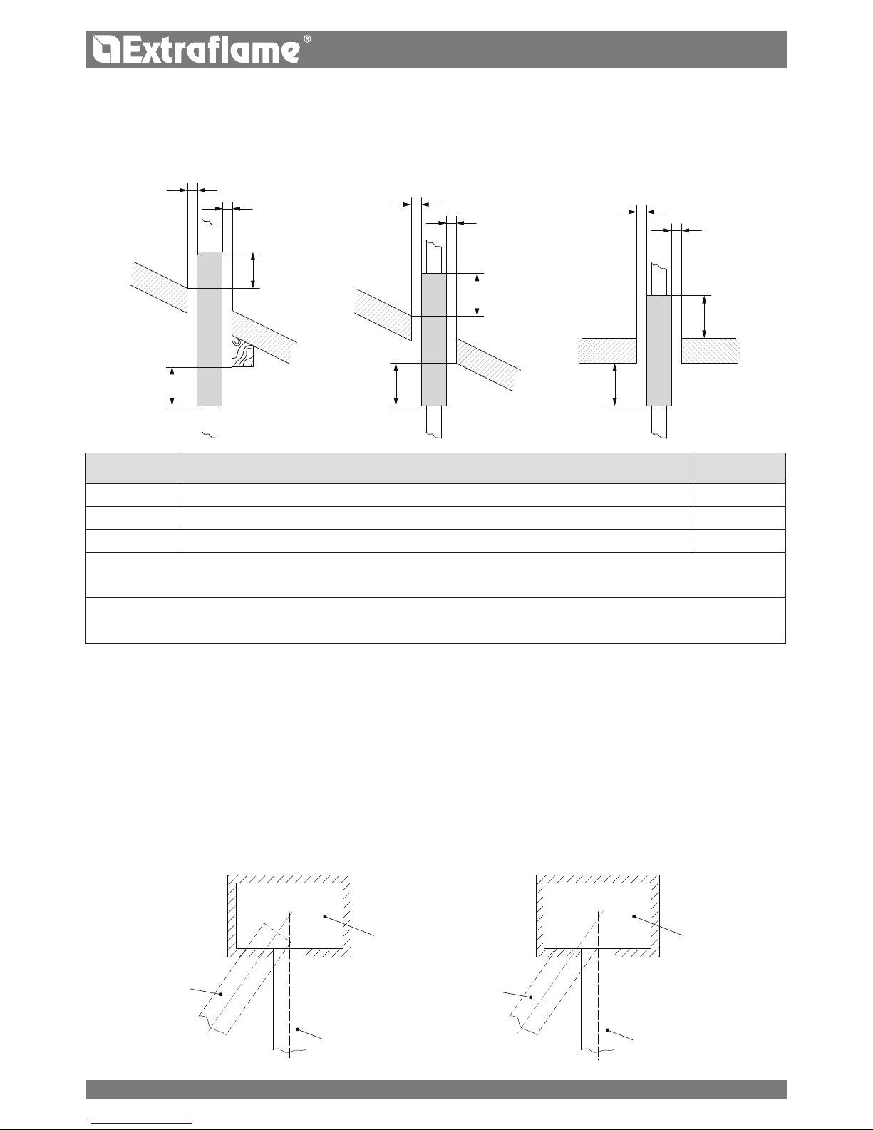
a
a
b.1
b
a
a
a
a
b.1
b.1
b b
OK
OK
ITALIANO
CANALI DA FUMO
Requisiti generali
l canali da fumo devono essere installati nel rispetto delle prescrizioni generali seguenti:
essere predisposti con almeno una presa a tenuta per eventuale campionamento fumi;
essere coibentati se passano all'interno di locali da non riscaldare o esterni all'edicio;
non devono attraversare locali nei quali è vietata l' installazione di apparecchi a combustione, né altri locali compartimentati
al fuoco o con pericolo incendio, né locali e/o spazi non ispezionabili;
essere installati in modo da consentire le normali dilatazioni termiche;
essere ssati all'imbocco del camino senza sporgere all'interno;
non è ammesso l'utilizzo di tubi metallici essibili per il collegamento dell'apparecchio al camino;
diametro nominale;
distanza dai materiali combustibili, indicata in millimetri, seguita dal simbolo della freccia e dalla amma;
dati dell'installatore e data di installazione.
Ogni qualvolta si devono attraversare materiali combustibili devono essere rispettate le seguenti indicazioni:
SIMBOLO DESCRIZIONE QUOTAMM
b Distanza minima dai materiali combustibili dall'intradosso dell'impalcato/solaio/parete 500
b.1 Distanza minima dai materiali combustibili dall'estradosso dell'impalcato/solaio 500
a Distanza minima dai materiali combustibili denita dal fabbricante G(xxx)
Con il colore bianco si deniscono i condotti monoparete.
Con il colore grigio si deniscono i sistemi camino in doppia parete coibentata.
È possibile derogare dalla quota A solo nel caso si utilizzi un opportuno schermo (per esempio: rosone) di protezione al
calore l'intradosso dell'impalcato/solaio
Camino
Camino
Sbagliato
Corretto
23
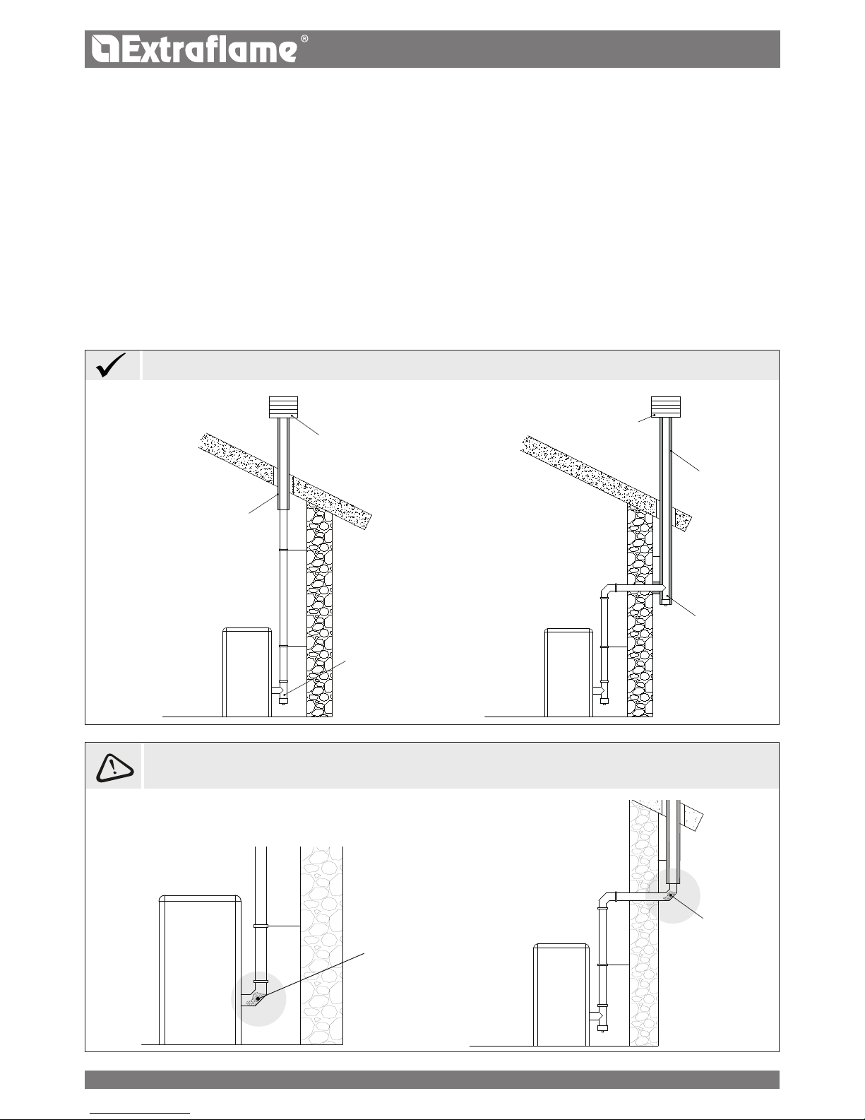
ITALIANO
non sono ammessi tratti in contro-pendenza;
i canali da fumo devono avere, per tutta la loro lunghezza un diametro non minore di quello dell'attacco del condotto di
scarico dell'apparecchio; eventuali cambiamenti di sezione sono ammessi solo in corrispondenza dell'imbocco al camino;
essere installati in modo da limitare la formazione di condense ed evitarne la fuori uscita dalle giunzioni;
devono essere posizionati ad una distanza dai materiali combustibili non minore a quella indicata nella designazione di prodotto;
il canale da fumo/condotto deve permettere il recupero della fuliggine ed essere scovolabile ed ispezionabile previo
smontaggio o attraverso aperture di ispezione quando non accessibile dall'interno dell'apparecchio.
PRESCRIZIONI AGGIUNTIVE PER APPARECCHI MUNITI DI ELETTROVENTIL ATORE PER L'ESPULSIONE DEI FUMI
Per gli apparecchi generatori di calore muniti di elettroventilatore per l’espulsione dei fumi, dovranno essere rispettate le
seguenti istruzioni:
I tratti orizzontali devono avere una pendenza minima del 3% verso l’alto
La lunghezza del tratto orizzontale deve essere minima e comunque non superiore a 3 metri
Il numero di cambi di direzione compreso quello per eetto dell’impiego di elemento a “T” non deve essere superiore a 4 .
Cenere depositata
nella curva 90°
Cenere depositata
nella curva 90°
Installazione con canna fumaria
interna
Protezione dalla
pioggia e vento
Protezione dalla
pioggia e vento
Canna fumaria
coinbentata
Raccordo a
"T" coibentato
anticondensa con
tappo di ispezione
Raccordo a "T"
anticondensa con
tappo di ispezione
Canna fumaria
coinbentata
Installazione con canna fumaria
interna - esterna
E’ SCONSIGLIATO INSTALLARE COME PRIMA PARTE INIZIALE UNA CURVA A 90°, POICHÉ LA CENERE OSTRUIREBBE
IN POCO TEMPO IL PASSAGGIO DEI FUMI, CAUSANDO PROBLEMI AL TIRAGGIO DEL GENERATORE. VEDI FIGURE
SOTTO:
ESEMPI DI CORRETTO COLLEGAMENTO AL CAMINO
24
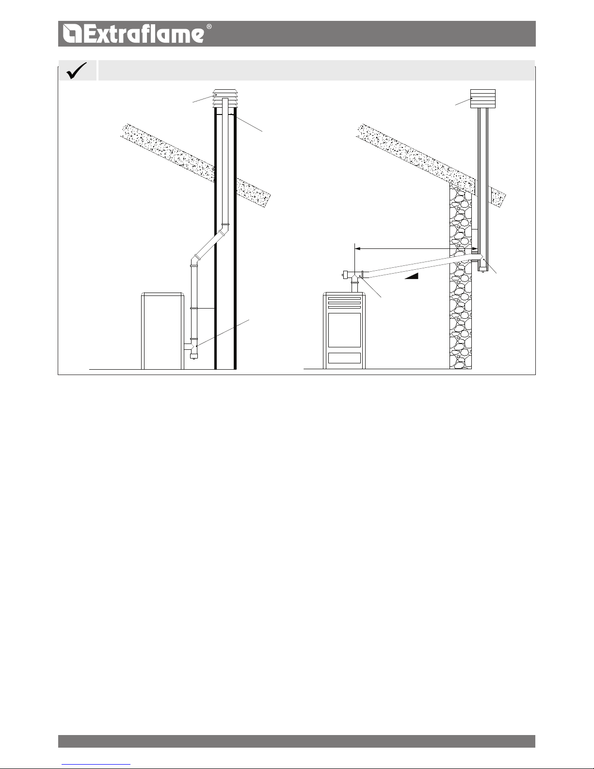
3 - 5%
Max 3 mt
ITALIANO
E’ obbligatorio l’utilizzo di tubazioni a tenuta.
CAMINO
l camini per l'evacuazione in atmosfera dei prodotti della combustione in aggiunta ai requisiti generali indicati devono:
funzionare in pressione negativa (non è ammesso il funzionamento in pressione positiva);
avere sezione interna di forma preferibilmente circolare; le sezioni quadrate o rettangolari devono avere angoli arrotondati
con raggio non minore di 20 mm (sezioni idraulicamente equivalenti possono essere utilizzate purché il rapporto tra il lato
maggiore ed il lato minore del rettangolo, che circoscrive la sezione stessa, non sia comunque maggiore di 1 ,5);
essere adibiti ad uso esclusivo dell'evacuazione dei fumi;
avere andamento prevalentemente verticale ed essere privi di qualsiasi strozzatura per tutta la loro lunghezza;
avere non più di due cambiamenti di direzione con un angolo d'inclinazione non maggiore di 45°;
essere dotati, nel caso di funzionamento ad umido, di un dispositivo per il drenaggio dei reui (condensa, acqua piovana)
Sistema intubato
Un sistema intubato può essere realizzato con uno o più condotti per intubamento funzionanti solo con pressione negativa
rispetto all'ambiente.
Il tubo essibile conforme alla UNI EN 1856-2, con caratteristiche T400-G soddisfa i requisiti.
COMIGNOLI
I comignoli devono soddisfare i requisiti seguenti:
avere sezione utile di uscita non minore del doppio di quella del camino/sistema intubato sul quale è inserito;
essere conformati in modo da impedire la penetrazione nel camino/sistema intubato di pioggia e neve;
essere costruiti in modo che, anche in caso di venti provenienti da ogni direzione ed con qualsiasi inclinazione, venga
comunque assicurata l'evacuazione dei prodotti della combustione;
devono essere privi di ausili meccanici di aspirazione.
Raccordo a "T"
con tappo di
ispezione
Lamiera in
acciaio
a tenuta stagna
Raccordo a
"T" coibentato
con tappo di
ispezione
Protezione dalla
pioggia e vento
Protezione dalla
pioggia e vento
Raccordo a "T" con
tappo di ispezione
ESEMPI DI CORRETTO COLLEGAMENTO AL CAMINO
25
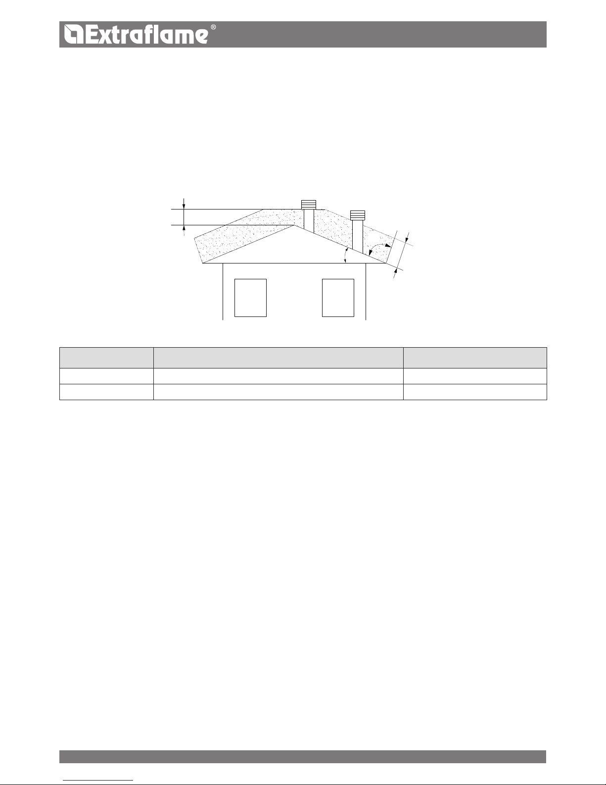
90°
c
a
ß
ITALIANO
Lo sbocco di un camino/sistema intubato non deve essere in prossimità di ostacoli che potrebbero creare zone di turbolenza
e/o ostacolare la corretta evacuazione dei prodotti della combustione e le operazioni di manutenzione da eettuarsi a tetto.
Vericare la presenza di altri comignoli o lucernari e abbaini.
REQUISITI DI PRODOTTO PER IL SISTEMA DI EVACUAZIONE FUMI
Classe di temperatura
Nel caso di apparecchio a pellet non sono ammesse classi di temperatura minori di T200.
Classe di resistenza al fuoco di fuliggine
Per sistema di evacuazione fumi asservito ad apparecchi alimentati con combustibili solidi è richiesta la resistenza al fuoco della
fuliggine, quindi la designazione deve essere indicata con la lettera G seguita dalla distanza dai materiali combustibili espressa
in millimetri (XX) (secondo la UNI EN 1443).
Nel caso di apparecchi a pellet i sistemi di evacuazione fumi devono essere a tenuta , se si utilizzino elementi a doppia
designazione (G e O, con o senza elastomero di tenuta) per il collegamento dell'apparecchio al camino, deve essere osservata
la distanza minima XX espressa in millimetri indicata per la designazione G; in caso di incendio da fuliggine si deve provvedere
al ripristino delle condizioni iniziali (sostituzione delle guarnizioni ed elementi danneggiati e pulizia di quelli rimasti in uso).
Prove di accensione
Il funzionamento dell'apparecchio deve essere vericato con prova di accensione , ovvero:
per gli apparecchi ad alimentazione meccanica si deve ultimare la fase di accensione, vericarne il corretto funzionamento
almeno per i successivi 15 min e il regolare spegnimento;
Per gli apparecchi inseriti in un impianto di riscaldamento ad acqua calda (termocaminetti, termostufe), il collaudo deve
estendersi anche all'intero circuito idraulico.
QUOTA DI SBOCCO DEI PRODOTTI DELLA COMBUSTIONE
La quota di sbocco si determina misurando l'altezza minima che intercorre tra il manto di copertura e il punto inferiore della
sezione di uscita dei fumi in atmosfera; tale quota deve essere al di fuori della zona di reusso e a distanza adeguata da ostacoli
che impediscano o rendano dicoltosa l'evacuazione dei prodotti della combustione o da aperture o zone accessibili.
Zona di reusso
La quota di sbocco deve trovarsi al di fuori della zona di reusso calcolata in base alle seguenti indicazione riportate sotto.
In prossimità del colmo si considera la minore tra le due.
Zona di rispetto per quota di sbocco
Zona di ·rispetto per a quota di sbocco sopra il tetto in pendenza ( ß >10°)
RIFERIMENTO DESCRIZIONE ZONA DA RISPETTARE MM
c Distanza misurata a 90° dalla supercie del tetto 1300
a Altezza sopra il colmo del tetto 500
26
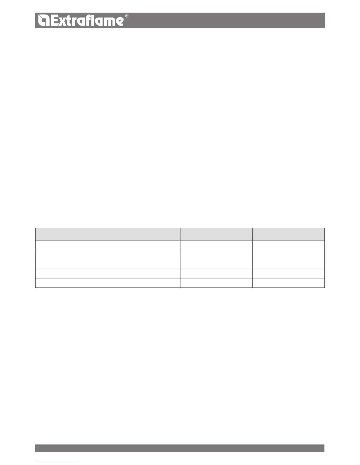
ITALIANO
Rivestimenti e niture
l rivestimenti e le niture devono essere applicati solo dopo aver vericato il corretto funzionamento dell'apparecchio secondo
le modalità indicate
DOCUMENTAZIONE TECNICA DELL'INSTALLAZIONE
Ad installazione conclusa, l'installatore deve consegnare al proprietario o a chi per esso, ai sensi della legislazione vigente, la
dichiarazione di conformità dell'impianto, correlata di:
1) il libretto d' uso e manutenzione dell' apparecchio e dei componenti dell'impianto (come per esempio canali da fumo,
camino, ecc.);
2) copia fotostatica o fotograca della placca camino;
3) libretto d'impianto (ove previsto).
Si raccomanda all'installatore di farsi rilasciare ricevuta della documentazione consegnata e conservarla unitamente a copia della
documentazione tecnica relativa all'installazione eettuata.
Installazione eettuata da soggetti diversi
Qualora le singole fasi dell'installazione siano svolte da soggetti diversi, ciascuno deve documentare la parte di lavoro svolto a
benecio del committente e dell'incaricato della fase successiva.
CONTROLLO E MANUTENZIONE
Periodicità delle operazioni
La manutenzione dell'impianto di riscaldamento e dell'apparecchio devono essere eseguiti con periodicità regolare in base alla
tabella sottostante:
TIPOLOGIA DI APPARECCHIO INSTALLATO <15kW (15- 35) kW
Apparecchio a pellet 1 anno 1 anno
Apparecchi ad acqua
(termocamini, termostufe, termocucine )
1 anno 1 anno
Caldaie 1 anno 1 anno
Sistema evacuazione fumi 4 t di combustibile utilizzato 4 t di combustibile utilizzato
Maggiori dettagli consultare il capitolo " pulizia e manutenzione".
Rapporto di controllo e manutenzione
Al termine delle operazioni di controllo e/o manutenzione deve essere redatto un rapporto da rilasciare al proprietario, o chi
per esso, che ne deve confermare per iscritto il ricevimento. Nel rapporto devono essere indicate le situazioni riscontrate, gli
interventi eettuati, gli eventuali componenti sostituiti o installati e le eventuali osservazioni, raccomandazioni e prescrizioni.
Il rapporto deve essere conservato congiuntamente alla documentazione pertinente.
Nel rapporto di controllo e manutenzione si deve fare menzione di:
anomalie accertate e non eliminabili, che comportino rischi per l'incolumità dell'utilizzatore o di danno grave al fabbricato;
componenti manomessi.
Nel caso fossero individuate anomalie di cui sopra il proprietario, o chi per esso, deve essere didato in forma scritta, nel
rapporto di manutenzione, dall'utilizzare l'impianto no al completo ripristino delle condizioni di sicurezza.
Nel rapporto di controllo e manutenzione devono essere indicati i dati signicativi del tecnico o dell'impresa che ha eseguito le
operazioni di controllo e/o manutenzione con i relativi recapiti, la data dell'intervento e la rma dell'operatore.
27
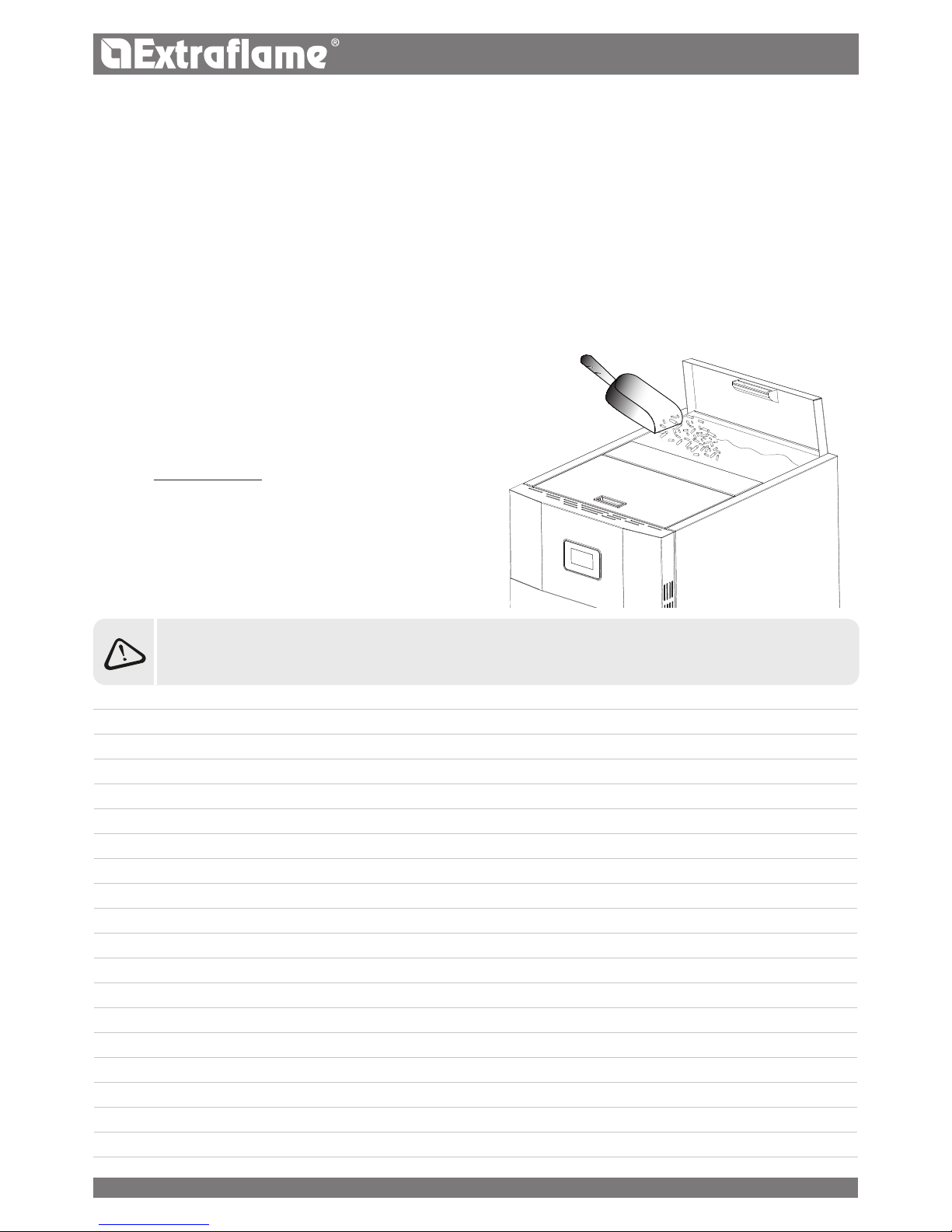
ITALIANO
PELLET E CARICAMENTO
I pellets vengono realizzati sottoponendo ad un’altissima pressione la segatura, ossia gli scarti di legno puro (senza vernici)
prodotti da segherie, falegnamerie ed altre attività connesse alla lavorazione e alla trasformazione del legno.
Questo tipo di combustibile è assolutamente ecologico in quanto non si utilizza alcun collante per tenerlo compatto. Infatti, la
compattezza dei pellets nel tempo è garantita da una sostanza naturale che si trova nel legno: la lignite.
Oltre ad essere un combustibile ecologico, in quanto si sfruttano al massimo i residui del legno, il pellet presenta anche dei
vantaggi tecnici.
Mentre la legna presenta un potere calorico di 4,4 kWh/kg. (con il 15% di umidità, quindi dopo circa 18 mesi di stagionatura),
quello del pellet è di 5 kWh/kg.
La densità del pellet è di 650 kg/m3 ed il contenuto d’acqua è pari all’8% del suo peso. Per questo motivo non è necessario
stagionare il pellet per ottenere una resa calorica sucientemente adeguata.
L’IMPIEGO DI PELLETS SCADENTI O DL QUALSIASI ALTRO MATERIALE, DANNEGGIA LE FUNZIONI DEL
GENERATORE E PUÒ DETERMINARE LA CESSAZIONE DELLA GARANZIA E L’ANNESSA RESPONSABILITÀ DEL
PRODUTTORE.
Il pellet utilizzato dovrà essere conforme alle caratteristiche
descritte dalle norme:
EN PLUS UNI EN 16961 2 classe A1 oppure A2
ÖNORM M 7135
DIN PLUS 51731
Il fabbricante per i propri prodotti consiglia sempre di utilizzare
pellet del diametro di 6 mm.
IMMAGAZZINAMENTO PELLET
Per garantire una combustione senza problemi è necessario che
il pellet sia conservato in un luogo non umido.
Aprire il coperchio del serbatoio e caricare il pellet con l’ausilio
di una sessola.
28
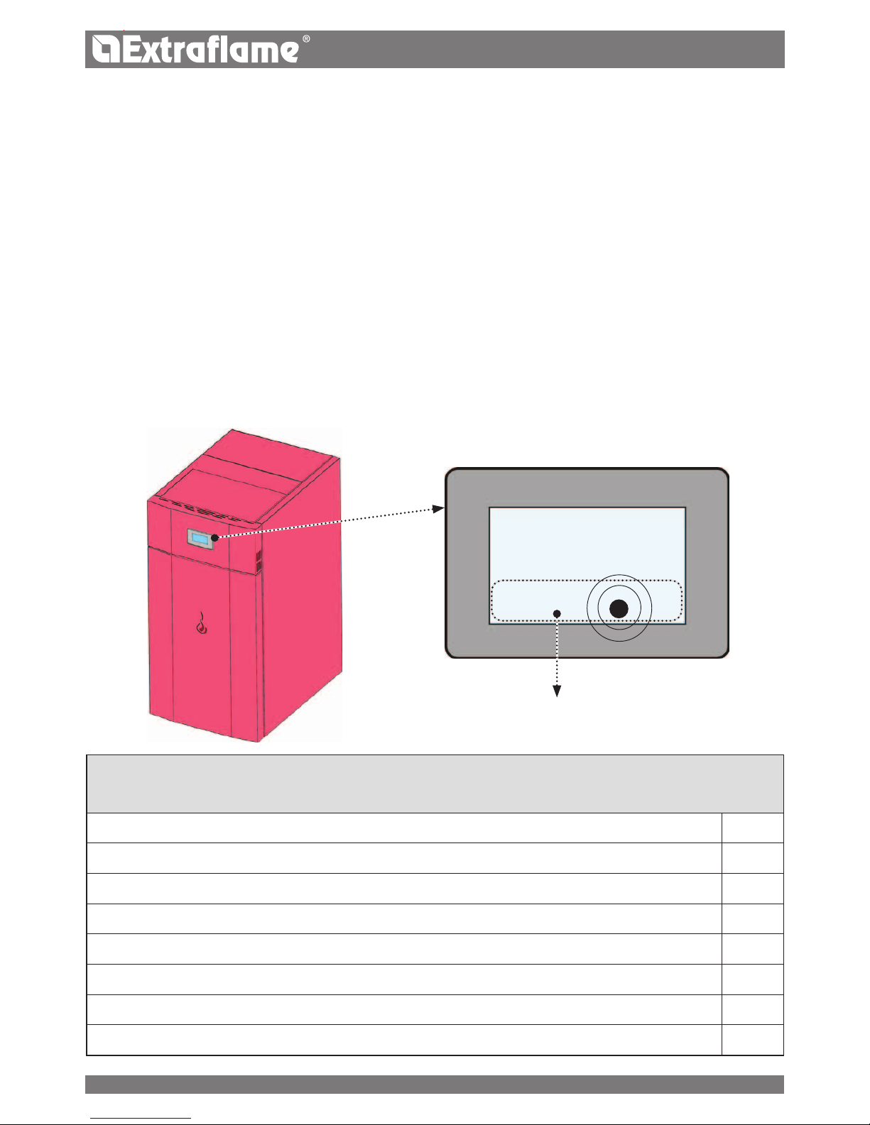
29ITALIANO
DISPLAY TOUCH SCREEN
La caldaia è equipaggiata con un moderno display touch-screen che permette la regolazione delle singole funzioni
dell'apparecchio in modo facile ed intuitivo da parte del utente.
Tutte le regolazioni ed impostazioni ragurate nelle schermate possono essere eseguite direttamente tramite il display touchscreen integrato.
Toccando i pulsanti (icone) sulla supercie di visualizzazione vengono attivate le azioni. La supercie del display touch-screen
reagisce con il tocco delle dita.
ATTENZIONE
Non utilizzate pellicole protettive, ciò potrebbe causare il mal funzionamento del display
Non mettete il display touch-screen a contatto diretto o indiretto con l'acqua. Il display touch-screen potrebbe non
funzionare correttamente in presenza di umidità o se esposto ad acqua.
Per evitare di danneggiare il display touch-screen, non deve essere toccato con oggetti appuntiti e non deve essere
esercitato eccessiva pressione con le dita.
PARTE SENSIBILE AL TATTO
Il produttore dispone di una scheda supplementare optional che permette alla caldaia le seguenti ulteriori
funzioni nella gestione dell’impianto. Nella tabella sottostante vengono indicate le varie possibilità che l’optional
può orire.
Gestione Accumulo sanitario
P
Gestione Puer
P
3 zone riscaldamento
P
Opzione acqua sanitaria istantanea
P
Gestione pompa puer o 4^ zona riscaldamento
P
Gestione antilegionella per accumulo sanitario
P
Gestione crono accumulo sanitario
P
Gestione e controllo uscita ausiliaria
P
L
29
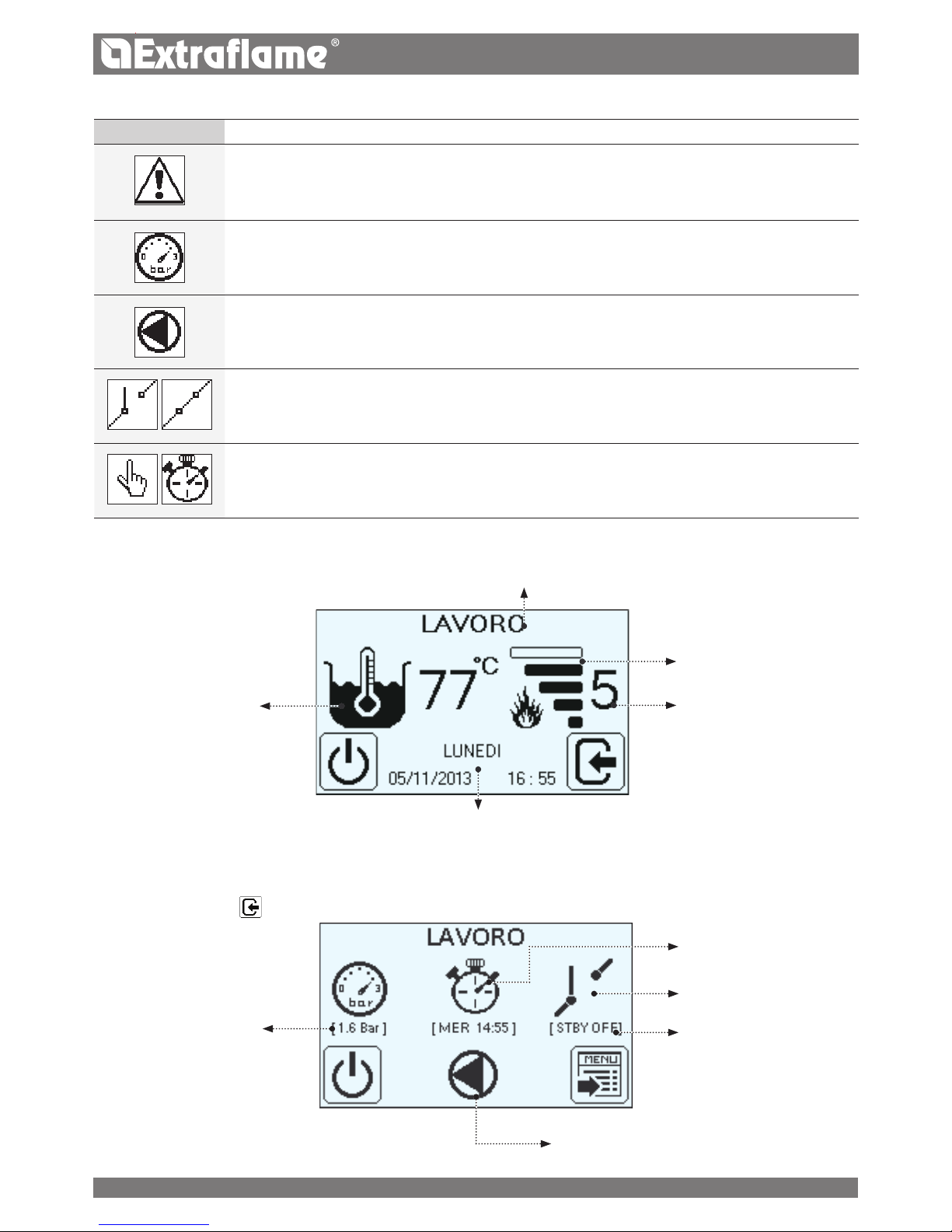
30 ITALIANO
QUADRO COMANDI E ICONE
VISUALIZZAZIONE DEI VAR I
MESSAGGI DI TESTO
POTENZA IMPOSTATA
POTENZA REALE
TEMPERATURA
H2O CALDAIA
Premendo brevemente appaiono delle informazioni aggiuntive, esempio:
PRESSIONE RILEVATA IN
CALDAIA
STATO DEL CONTATTO
ESTERNO
CIRCOLATORE, SE ATTIVO
CRONO ATTIVO
O FUNZIONE MANUALE
ICONA SIGNIFICATO
• Indica la presenza di una anomalia/ allarme. La macchina andrà in spegnimento.
• Indica la pressione dell'impianto rilevato dalla macchina.
• Indica il funzionamento del circolatore: Spenta = circolatore è disattivo ; Accesa = circolatore è attivo
Lampeggiante = è attiva la sicurezza (temperatura H2O > 85°C)
• Indica il contatto del termostato supplementare esterno
Contatto chiuso: il contatto del termostato supplementare esterno è chiuso.
Contatto aperto: il contatto del termostato supplementare esterno è aperto.
• Indica lo stato di funzionamento della macchina, funzionamento manuale o con programmazione settimanale.
Icona mano: la funzione la programmazione settimanale e disattivata (gestione manuale)
Icona crono: e attiva la funzione la programmazione settimanale
FUNZIONE STBY
GIORNO, DATA, ORA, ANNO
30

31ITALIANO
STRUTTURA MENU
ISTRUZIONI DI BASE
Durante le prime accensioni del generatore si deve prestare
attenzione ai seguenti consigli:
E’ possibile che vengano prodotti dei leggeri odori
dovuti all’essiccazione delle vernici e dei siliconi utilizzati.
Evitare una permanenza prolungata nell'ambiente.
Non toccare le superci in quanto potrebbero essere
ancora instabili.
Aerare bene il locale più volte.
L’indurimento delle superci viene terminato dopo
alcuni processi di riscaldamento.
Questo apparecchio non deve essere utilizzato come
inceneritore di riuti.
Prima di procedere con l’accensione del geratore è necessario
vericare i seguenti punti:
L'impianto idraulico deve essere terminato, rispettare le
indicazioni delle normative e del manuale.
Il serbatoio deve essere carico di pellet
La camera di combustione deve essere pulita
Il braciere deve essere completamente libero e pulito
Vericare la chiusura ermetica della porta fuoco e del
cassetto cenere
Vericare che il cavo di alimentazione sia collegato
correttamente
L'interruttore bipolare nella parte posteriore destra deve
essere posto su 1.
SET POTENZA
SET TEMPERATURE
SET REGOLAZIONI
STATO
MENÙ UTENTE
TARATURE TECNICO
RISERVATO AL TECNICO ABILITATO
STATO 1 2
PUL BRACIERE
STAND BY
ABILITA CRONO
PELLET
SET H2O
SET OROLOGIO
SET CRONO
LINGUA
DISPLAY
BLOCCO TASTI LUMINOSITÀ
RESET
TASTO FUNZIONE
Tenete premuto per più di 2 secondi per
accendere o spegnere la caldaia.
Tenete premuto per più di 2 secondi per
uscire dal menu.
Premendo brevemente è possibile tornare
indietro di un passo.
Permette di accedere alle info aggiuntive.
Permette di accedere al menu utente.
TASTO FUNZIONE
Consente di aumentare/selezionare (+) o
di diminuire (-) una impostazione (SET)
Consente di scorrere attraverso nei menu
Consente di attivare (ON) o disattivare (OFF)
Consente di retrocedere di un passo se
premuto brevemente, se premuto più a
lungo permette di uscire sino alla scremata
principale.
SET POTENZA
FUNZIONE TASTI
31

32 ITALIANO
NON UTILIZZARE ALCUN LIQUIDO INFIAMMABILE PER L’ ACCENSIONE!
IN FASE DI RIEMPIMENTO NON PORTARE IL SACCO DI PELLET A CON TATTO CON IL GENERATORE CALDO!
NEL CASO DI CONTINUE MANCANTE ACCENSIONI CONTATTARE UN TECNICO AUTORIZZATO.
SET OROLOGIO
Il set orologio consente di regolare l’orario e la data
SET LINGUA
Consente di impostare una delle lingue disponibili: Italiano - Inglese - Francese - Tedesco - Spagnolo.
IMPOSTAZIONI PER LA PRIMA ACCENSIONE
Una volta collegato il cavo di alimentazione nella parte posteriore del generatore, portare l’interruttore, sempre situato
posteriormente, nella posizione (I).
L’interruttore posto posteriormente al generatore serve per dare tensione alla scheda del generatore.
Il generatore rimane spenta e sul pannello compare una prima schermata con la scritta OFF .
FREQUENZA DI RETE 50/ 60HZ
Nel caso in cui il generatore sia installata in un paese con una frequenza di 60Hz, il generatore in visualizzerà "frequenza rete
errata ". Variare nel caso la frequenza a 60Hz.
32

33ITALIANO
FUNZIONAMENTO E LOGICA
ACCENSIONE
Una volta vericati le "istruzioni di base" precedentemente elencati, premere il per più di due secondi per accendere il
generatore.
Per la fase di accensione sono a disposizione 15 minuti, dopo l'avvenuta accensione e raggiungimento della temperatura di
controllo, il generatore interrompe la fase di accensione e passa in AVVIAMENTO.
AVVIAMENTO
Nella fase di avviamento il generatore stabilizza la combustione, aumentando progressivamente la combustione, e passando
in LAVORO.
LAVORO
Nella fase di lavoro il generatore si porterà nel set potenza impostato, vedi voce seguente.
REGOLAZIONE SET POTENZA
Impostare la potenza di funzionamento da 1 a 5.
Potenza 1 = livello minimo - Potenza 5 = livello massimo.
REGOLAZIONE SET TEMPERATURA H2O
Impostare la temperatura caldaia da 65 - 80°C .
FUNZIONAMENTO DEL CIRCOLATORE
Il circolatore attiva la circolazione dell’acqua quando nel generatore la t° dell’acqua raggiunge 60° C. Essendo il circolatore
sempre in funzionamento sopra i 60°, si consiglia una zona di riscaldamento sempre aperta per rendere più omogeneo il
funzionamento del prodotto, ed evitare blocchi per sovratemperatura, di solito questa zona viene denita “zona di sicurezza”.
PULIZIA BRACIERE
A intervalli prestabiliti il generatore eettua una pulizia del braciere, portando la macchina in spegnimento.
Terminata la fase di pulizia, il generatore si riaccenderà in automatico e proseguirà il suo lavoro portandosi nuovamente alla
potenza selezionata.
MODULAZIONE e H-OFF
A mano a mano che la temperatura dell’acqua si avvicina al set impostato la caldaia inizia a modulare portandosi
automaticamente alla minima potenza.
Se la temperatura aumenta superando il set impostato si porterà automaticamente in spegnimento segnalando HOFF, per
riaccendersi sempre in automatico appena la temperatura scende al di sotto del set impostato.
SPEGNIMENTO
Premere il tasto 1 per tre secondi.
Eseguita questa operazione l’apparecchio entra automaticamente nella fase di spegnimento, bloccando la fornitura dei pellets.
Il motore di aspirazione dei fumi resterà acceso no a che la temperatura del generatore non sarà scesa sotto i parametri di
fabbrica.
RIACCENSIONE
La riaccensione sia in automatico che manuale del generatore è possibile, solo quando le condizioni del ciclo di rareddamento
e il timer preimpostato sono state assolte.
33

34 ITALIANO
TERMOSTATO AMBIENTE SUPPLEMENTARE
N.B. : L’installazione deve essere eseguita da un tecnico autorizzato
Esiste la possibilità di termostatare un locale adiacente alla stanza dove è stata posizionato il generatore è suciente collegare
un termostato ambiente seguendo la procedura descritta al punto successivo (è consigliabile posizionare il termostato ambiente
meccanico opzionale ad un’altezza dal pavimento di 1,50 m). Il funzionamento del generatore con il termostato esterno collegato
nel morsetto STBY può essere diverso in base dall’ attivazione o disattivazione della funzione STBY.
Di fabbrica il morsetto STBY esce ponticellato per cui è sempre con contatto chiuso (in richiesta).
FUNZIONAMENTO TERMOSTATO AMBIENTE SUPPLEMENTARE CON STBY ATTIVO STBY ON
Quando il contatto o termostato esterno sarà soddisfatto (contatto aperto / temperatura raggiunta) il generatore andrà in
spegnimento. Appena il contatto o termostato esterno passerà allo stato “non soddisfatto” (contatto chiuso / temperatura da
raggiungere) si riavrà l’accensione.
Nota bene: il funzionamento del generatore è comunque dipendendente dalla temperatura dell’acqua interna al
termoprodotto e relativi vincoli di fabbrica impostati. Se il generatore è in H OFF (temperatura dell’acqua raggiunta), la
richiesta eventuale del contatto o termostato supplementare verrà ignorata.
FUNZIONAMENTO TERMOSTATO AMBIENTE SUPPLEMENTARE CON STBY DISATT IVO STBY OFF
Quando il contatto o termostato esterno sarà soddisfatto (contatto aperto / temperatura raggiunta) il generatore si porterà
al minimo. Appena il contatto o termostato esterno passerà allo stato “non soddisfatto” (contatto chiuso / temperatura da
raggiungere) il generatore ricomincerà a lavorare alla potenza pre-impostata.
Nota bene: il funzionamento del generatore è comunque dipendendente dalla temperatura dell’acqua interna al
generatore e relativi vincoli di fabbrica impostati. Se il generatore è in H OFF (temperatura dell’acqua raggiunta), la richiesta
eventuale del contatto o termostato supplementare verrà ignorata.
INSTALLAZIONE TERMOSTATO AMBIENTE SUPPLEMENTARE
Spegnere l’apparecchio utilizzando l’interruttore generale posto nel retro del generatore.
Togliere la spina dalla relativa presa di corrente.
Facendo riferimento allo schema elettrico, collegare i due cavetti del termostato nei relativi morsetti posti sul retro della
macchina, uno di colore rosso e l’altro nero (morsetto STBY).
AUX
Collegamento riservato per gli accessori del produttore a onde convogliate.
Per maggiori informazioni contattare il rivenditore.
HP30 HP15 - 22
AUX
STBY
H
STBY
AUX
AUX
STBY
34

35ITALIANO
SET POTENZA
Il seguente menù permette di impostare il set di potenza. Potenza minima 1, potenza massima 5.
SET TEMPERATURE
Il seguente menù permette di impostare la temperatura della caldaia Le impostazioni possibili sono: 65 - 80°C.
SET REGOLAZIONI
Il SET REGOLAZIONE consente di:
Regolare la frequenza della PULIZIA BRACIERE
Abilitare/ disabilitare lo STAND BY
Abilitare/ disabilitare il CRONO
Regolare il PELLET in percentuale.
• PUL BRACIERE
Il menù permette di aumentare la frequenza della pulizia
automatica del braciere. (Range 0-50)
• STAND BY
La funzione Stby viene utilizzata nel caso si desideri uno
spegnimento immediato del generatore o una modulazione
tramite termostato supplementare.
35

36 ITALIANO
• ABILITA CRONO
Consente di abilitare/disabilitare il crono e le diverse fasce orarie della caldaia
• REGOLAZIONE PELLET
Il seguente menù permette la regolazione in percentuale del
carico del pellet.
Nel caso il generatore presenti dei problemi di funzionamento
dovuti alla quantità dei pellets si può procedere direttamente
dal quadro comandi alla regolazione del carico pellet.
I problemi correlati alla quantità di combustibile possono
essere suddivisi in 2 categorie:
CARENZA DI COMBUSTIBILE:
il generatore non riesce mai a sviluppare una amma adeguata tendendo a rimanere sempre molto bassa anche a potenza
elevata.
alla minima potenza il generatore tende quasi a spegnersi portando il generatore in allarme “MANCANO PELLET”.
quando il generatore visualizza l’allarme “MANCANO PELLET” può esserci del pellet incombusto (non bruciato) all’interno del
braciere.
ECCESSO DI COMBUSTIBILE:
il
generatore
sviluppa una amma molto alta anche a basse potenze.
tende a sporcare molto il vetro panoramico oscurandolo quasi totalmente.
il braciere tende ad incrostarsi otturando i fori per l’aspirazione dell’aria a causa dell’eccessivo pellet caricato in quanto
viene bruciato solo parzialmente.
La regolazione da eseguire è di tipo percentuale, quindi una modica su questo parametro comporterà una variazione
proporzionale su tutte le velocità di caricamento del
generatore
.
Il caricamento e possibile nel ordine di -30% a +20%.
STATO
Riferimenti riservati al tecnico
MENU UTENTE
ll MENU UTENTE consente di:
Impostare data e ora (vedi capitolo prima accensione)
Impostare il la programmazione CRONO
Impostare la LINGUA
Impostare il DISPLAY
Utilizzare il RESET
36

37ITALIANO
RACCOMANDAZIONI ESEMPIO
Gli orari di accensione e spegnimento devono essere
compresi nell’arco di un’unica giornata, dalle 0 alle 24, e
non accavallate in più giorni.
Prima di utilizzare la funzione crono è necessario impostare
il giorno e l’orario corrente, per cui vericare di aver seguito
i punti elencati al sottocapitolo “Set orologio” per fare in
modo che la funzione crono lavori, oltre che a programmarla
occorre anche attivarla.
Accensione ore 07:00
CORRETTO
Spegnimento ore 18:00
Accensione ore 22:00
SBAGLIATO
Spegnimento ore 05:00
• CRONO
Il crono consente di programmare 4 fasce orarie all’interno di
una giornata da utilizzare per tutti i giorni della settimana.
In ogni fascia possono essere impostati l’orario di accensione
e spegnimento, i giorni di utilizzo della fascia programmata
e la temperatura acqua (65 - 80°C) desiderata.
PER ABILITARE IL CRONO SEGUIRE LE INDICAZIONI DESCRITTE
NEL CAPITOLO "ABILITA CRONO"
Orario di accensione
Orario di spegnimento
Set temperatura
Giorni abilitati
R
Giorni non abilitati
1= Lunedì
7= Domenica
Avanti
Indietro
Impostazione
• LINGUA
(vedi capitolo prima accensione)
• DISPLAY
- Cicalino
- Luminosità
- Contrasto
Il menu Display consente di:
Abilitare/ disabilitare la segnalazione acustica.
Regolare l’intensità luminosa del display
Regolare il contrasto del display
37

38 ITALIANO
CICALINO
Quando si imposta "OFF" viene disabilita la segnalazione
acustica.
LUMINOSITÀ
Consente di regolare la retroilluminazione del display.
Le impostazioni possibili sono da OFF - 10 a 30.
Attivando OFF, la retro illuminazione del display si spegnerà
dopo un ritardo preimpostato.
La retro illuminazione si accenderà non appena verrà premuto
un tasto, o se la macchina dovesse andare in allarme.
CONTRASTO
Consente di modicare il contrasto del display.
( Range da 2-50)
• RESET
Consente di riportare tutti i valori modicabili dall’utente
come da fabbrica
ALTRE FUNZIONI
SCARICO ARIA
Questa funziona permette di scaricare l'eventuale aria presente nel termoprodotto. (per 15 minuti Il circolatore funziona in
modo alternato 30 secondi attivo e 30 sec disattivo.
Per attivare la funzione:
Con il generatore freddo e in stato "OFF" premere
e successivamente "AIR" per 5 sec.
Per arrestare la funzione "Scarico aria" premere il tasto
PRIMO CARICO
Questa funzione permette di attivare il motoriduttore di
caricamento del pellet per un funzionamento in continuo.
Per attivare la funzione:
Con il generatore freddo e in stato "OFF" premere
e
successivamente "LOAD" per 5 sec.
Per arrestare la funzione "Primo carico" premere il tasto
PULIZIA CAMERA COMBUSTIONE
Questa funzione permette di aprire il fondo braciere, agevolando la pulizia della camera di combustione.
Per attivare la funzione:
Con il generatore freddo e in stato "OFF" premere
e successivamente per 5 sec.
Con l’attizzatoio in dotazione raschiare le pareti della camera di combustione e far conuire la cenere residua della camera nel
braciere a cassetto cenere.
Terminata la pulizia, premere a lungo il tasto
.
APRIRE LA PORTA SOLO AD OPERAZIONE ESEGUITA! IL DISPLAY SEGNALERÀ L'AVVENUTA APERTURA!
SCARICO ARIAPRIMO CARICO
PULIZIA
38

ITALIANO
PULIZIA E MANUTENZIONE
Per un corretto funzionamento, il generatore deve subire una manutenzione ordinaria da parte di un tecnico abilitato, almeno
una volta all’anno. Le operazioni di controllo e manutenzione devono essere eseguite da operatori tecnici specializzati ed a
conoscenza delle indicazioni presenti in questo manuale.
ESEGUIRE LE INDICAZIONI SEMPRE NELLA MASSIMA SICUREZZA!
Assicurarsi che la spina del cavo di alimentazione sia staccata in quanto il generatore potrebbe essere stata programmata
per accendersi.
Che il generatore sia freddo in ogni sua parte.
Le ceneri siano completamente fredde.
Garantire una ecace ricambio d'aria dell’ambiente durante le operazioni di pulizia del prodotto.
Una scarsa pulizia pregiudica il corretto funzionamento e la sicurezza!
SE IL CAVO DI ALIMENTAZIONE È DANNEGGIATO, D EVE ESSERE SOSTITUITO DAL SERVIZIO DI ASSISTENZA
TECNICA O COMUNQUE DA UNA PERSONA CON QUALIFICA SIMILARE, IN MODO DA PREVENIRE OGNI
RISCHIO.
OGNI ANNO FAR PULIRE L’IMPIANTO DI SCARICO FUMI, CANALI DA FUMO E RACCORDI A “ T ” C OMPRESI
E TAPPI D'ISPEZIONE SE PRESENTI CURVE E GLI EVENTUALI TR ATT I ORIZZONTALI!
LA FREQUENZA DI PULIZIA DEL GENERATORE SONO INDICATIVI! DIPENDONO DALLA QUALITÀ DEL
PELLET UTILIZ ZATO E DALLA FREQUENZA DI UTILIZZO.
PUÒ SUCCEDERE CHE TALI OPERAZIONI DEBBANO ESSERE COMPIUTE CON MAGGIORE FREQUENZA.
PULIZIA E MANUTENZIONE A CARICO DEL UTENTE
Le operazioni di pulizia a carico del utilizzatore del generatore devono essere eseguite prestando massima cura dopo aver letto
le indicazioni relative alla procedure descritte in questo manuale.
MANUTENZIONE DELLE SUPERFICI E RIVESTIMENTO
La pulizia delle superci deve avvenire a generatore e rivestimento completamente freddo. Per la manutenzione delle superci
e parti metalliche, e suciente utilizzare un panno inumidito con acqua o con acqua e sapone neutro.
Non utilizzare mai detergenti abrasivi o diluenti aggressivi per la pulizia! Il non rispetto delle indicazioni può danneggiare le
superci del generatore.
PULIZIA VETRO CERAMICO
La pulizia del vetro ceramico deve avvenire solo a vetro completamente freddo. Pulire il vetro ceramico utilizzando un pennello
asciutto o in caso di molto sporco un detergente specico spruzzandone una modesta quantità su un panno e passandolo
successivamente sul vetro ceramico.
Non spruzzare il detergente o qualsiasi altro liquido direttamente sul vetro o sulle guarnizioni.
PULIZIA DEL SERBATOIO PELLET
Quando il serbatoio si svuota completamente, staccare il cavo di alimentazione del generatore e rimuovere prima i residui
(polvere, trucioli, ecc.) dal serbatoio vuoto, prima di procedere al suo riempimento.
MANUTENZIONE ORDINARIA
Al ne di garantire il buon funzionamento e la sicurezza dell'apparecchio è necessario eettuare le operazioni indicate in seguito
stagionalmente o con frequenza maggiore qualora sia necessario.
GUARNIZIONI PORTA, CASSETTO CENERE E BRACIERE
Le guarnizioni garantiscono l’ermeticità del
generatore
e il conseguente buon funzionamento della stessa.
E’ necessario che esse vengano periodicamente controllate: nel caso risultassero usurate o danneggiate è necessario sostituire
immediatamente.
Queste operazioni dovranno essere eseguite da parte di un tecnico abilitato.
39

ITALIANO
SETTIMANALMENTE CAMERA DI
COMBUSTIONE E CASSETTO CENERE:
Si raccomanda almeno una volta alla settimana di aspirare
i depositi di ceneri nella camera di combustione con un
aspirapolvere adeguato.
Per agevolare la pulizia consigliamo l'attivazione della
funzione "PULIZIA CAMERA DI COMBUSTIONE" Vedi capitolo
a
ALTRE FUNZIONI.
Settimanalmente o quando ce ne sia il bisogno, svuotare la
cenere dal cassetto previsto.
GIORNALIERA RASCHIATORI:
HSYSTEM 15/22: La pulizia degli scambiatori termici deve
avvenire solo a generatore freddo! La sua pulizia permette
di garantire nel tempo una resa termica sempre costante.
Questo tipo di manutenzione deve essere eseguita almeno
una volta al giorno. Per fare questo è suciente utilizzare
gli appositi raschiatori posti nella parte superiore del
generatore, eseguendo
il movimento dal basso verso l’alto e
viceversa più volte.
HSYSTEM 30: La pulizia degli scambiatori termici viene
eseguita in modo automatico tramite un sistema meccanico
che permette di garantire nel tempo una resa calorica
sempre costante.
GIORNALIERA BRACIERE:
Tramite un sistema meccanico la pulizia del braciere viene eseguita ad intervalli pressiate in modo automatico dalla caldaia.
Nella gura sotto si può notare il braciere con l’apertura sottostante.
Si consiglia comunque di asportare tramite un aspiracenere eventuali residui di cenere almeno 1 volta ogni 2 giorni .
40

D
E
A
C
C
HP15 - 22
C
HP30
ITALIANO
J
UN BRACIERE PULITO GARANTISCE UN CORRETTO FUNZIONAMENTO!
MANTENENDO IL BRACIERE E I SUOI FORI SEMPRE BEN PULITI
DA EVENTUALI RESIDUI DI COMBUSTIONE, SI GARANTISCE AL
GENERATORE UN’OTTIMA COMBUSTIONE NEL TEMPO, EVITANDO
EVENTUALI MALFUNZIONAMENTI CHE POTREBBERO RICHIEDERE
L’INTERVENTO DEL TECNICO.
È POSSIBILE UTILIZZARE LA FUNZIONE NEL MENU UTENTE "SET
REGOLAZIONE CARICO PELLET" PER ADEGUARE LA COMBUSTIONE
IN BASE ALLE ESIGENZE DESCRITTE.
FOR BRACIERE
MANUTENZIONE ORDINARIA
C
Camera di combustione & scambiatore (pulizia
totale) compreso pulizia condotto candeletta
D
Serbatoio (svuotamento completo e pulizia).
E
Verica tubo di aspirazione aria ed eventuale
pulizia del sensore di usso
A
Motore fumi (smontaggio e pulizia e condotto
fumi e "T"), nuovo silicone nei punti previsti
B
Guarnizioni ispezioni, cassetto cenere e porta
(sostituire e applicare silicone dove previsto)
TUTTE LE IMMAGINI SONO A SCOPO ILLUSTRATIVO.
41

C
D
B
B
D
C
E
A
HP30
HP15 - 22 - 30
ITALIANO
C
Camera di combustione & scambiatore (pulizia
totale) compreso pulizia condotto candeletta
D
Serbatoio (svuotamento completo e pulizia).
E
Verica tubo di aspirazione aria ed eventuale
pulizia del sensore di usso
A
Motore fumi (smontaggio e pulizia e condotto
fumi e "T"), nuovo silicone nei punti previsti
B
Guarnizioni ispezioni, cassetto cenere e porta
(sostituire e applicare silicone dove previsto)
MANUTENZIONE ORDINARIA
TUTTE LE IMMAGINI SONO A SCOPO ILLUSTRATIVO.
42

ITALIANO
VISUALIZZAZIONI
DISPLAY MOTIVAZIONE
OFF
Generatore
spento
START
È in corso la fase di start
CARICA PELLET
È in corso il carico continuo del pellet durante l’accensione
ACCENSIONE
È in corso la fase dedicata all’ accensione
AVVIO
È in corso la fase di avvio
LAVORO
E’ in corso la fase di lavoro normale
MODULA
Il
generatore
sta lavorando al minimo
PULIZIA BRACIERE
È in corso la pulizia del braciere
PULIZIA BRACIERE
DEPRESSIONE
È in corso la pulizia del braciere - causa depressione insuciente.
PULIZIA FINALE
È in corso la pulizia nale
STANDBY
Generatore spento in attesa di riaccendersi a causa del termostato esterno
Il generatore ripartirà quando il termostato esterno lo richiederà
ATTESA
RAFFREDDAMENTO
Viene tentata una nuova accensione quando il generatore è stata appena spenta Quando il generatore eettua
uno spegnimento è necessario attendere il completo spegnimento del motore fumi, quindi eettuare la pulizia
del braciere. Solo dopo aver eettuato queste operazioni sarà possibile riaccendere
il generatore
.
HOFF
Generatore spento per temperatura acqua superiore set impostato
Appena la temperatura dell’acqua si abbasserà sotto i parametri prestabiliti, il generatore si riaccenderà
ATTESA
BLACK OUT
Il generatore
si sta rareddando dopo una mancanza di corrente.
Concluso il rareddamento si riaccenderà in modo automatico
ANTIGELO
È in corso il funzionamento antigelo in quanto la t° H2O è sotto la soglia impostata di fabbrica
il circolatore si attiva sino a che l’acqua ha raggiunto il parametro preimpostato di fabbrica +2°C
ANTIBLOCCO
È in corso la funzione di antibloccaggio del circolatore (solo se il generatore è rimasto in stato di O per
almeno 96 ore) il circolatore si attiva per il tempo prestabilito dal costruttore, in modo da evitare il blocco
dello stesso
SOFFIO AUTO
E’ attivo il soo automatico
BLOCCO
SCAMBIATORE
La pulizia dello scambiatore risulta bloccata
ALLARMI
DISPLAY SPIEGAZIONE RISOLUZIONE
Indica la presenza di un allarme.
Accesa: indica la presenza di un allarme
Lampeggiante: indica la disattivazione del sensore di
depressione.
L’allarme può essere resettato solo se il motore fumi si è
fermato e sono trascorsi 15 minuti dalla visualizzazione
dell’allarme, premendo il tasto 1 per 3 secondi.
43

ITALIANO
ASPIRAT. GUASTO
Guasto motore fumi Contattare centro assistenza
SONDA FUMI
Guasto sonda fumi. Contattare centro assistenza
HOT FUMI
Temperatura fumi elevata
Controllare carico pellet (vedi “Regolazione carico pellet”), nel
caso non si risolvi contattare tecnico abilitato.
SERBATOIO
VUOTO
La porta non è chiusa correttamente.
Il cassetto cenere non è chiuso
correttamente.
La camera di combustione è sporca.
Il condotto di espulsione dei fumi è ostruito.
Vericare la presenza o meno di pellet all’interno del serbatoio.
Vericare la chiusura ermetica della porta.
Vericare la chiusura ermetica del cassetto cenere.
Vericare la pulizia sia del condotto fumi, sensore nel canale aria
primaria che della camera di combustione.
Contattare centro assistenza
MANCATA
ACCENSIONE
Il serbatoio del pellet è vuoto.
Taratura carico pellet inadeguata.
Vericare la presenza o meno di pellet all’interno del serbatoio.
Regolare l’ausso di pellet (vedi “Regolazione carico pellet”).
Vericare le procedure descritte al capitolo “Accensione”.
NO ACC
BLACK OUT
Mancanza di corrente durante la fase di
accensione.
Portare il
generatore
in OFF tramite il tasto 1 e ripetere le
procedure descritte al capitolo “Accensione”.
MANCANO PELLET
Il serbatoio del pellet è vuoto.
Carenza di carico di pellet.
Il motoriduttore non carica pellet.
Vericare la presenza o meno di pellet all’interno del serbatoio.
Regolare l’ausso di pellet(vedi “Regolazione carico pellet”).
ALL. DEPR
La porta non è chiusa correttamente.
Il cassetto cenere non è chiuso
correttamente.
La camera di combustione è sporca.
Il condotto di espulsione dei fumi è ostruito
Vericare la chiusura ermetica della porta.
Vericare la chiusura ermetica del cassetto cenere.
Vericare la pulizia sia del condotto fumi che della camera di
combustione.
SENSORE PRESSIONE
GUASTO
Sensore di usso difettoso.
Sensore scollegato
Sensore pressione guasta
Contattare centro assistenza
SOVRATEMP. H20
L'acqua all’interno del
generatore
ha superato
i 95°C.
Possibile aria nell’impianto.
Mancanza di circolazione adeguata.
Mancanza della zona di sicurezza o non
adeguata.
Possibile anomalia del circolatore.
Contattare centro assistenza
BLOCCO BOTOLA
La pulizia automatica del braciere
risulta bloccata.
Contattare centro assistenza
PRESSIONE H2O MIN
La pressione impianto letta dal pressostato è
troppo bassa.
Possibile presenza di aria nell’impianto.
Possibile carenza di acqua o perdite dovute
ad anomalie in qualche componente
dell’impianto.
Contattare centro assistenza
SONDA ACQUA
Guasto sonda H2O Contattare centro assistenza
PRESSIONE H2O MAX
La pressione dell’ acqua ha superato la
soglia massima
Vericare i vasi di espansione che non siano danneggiati o
sotto dimensionati
Vericare che l’impianto a freddo sia caricato alla pressione
corretta
COMANDO COCLEA
Funzionamento anomalo
carico pellet
Contattare assistenza
BLOCCO COCLEA
Funzionamento anomalo
motore pellet
Contattare assistenza
SONDA BOILER
Guasto sonda boiler Contattare centro assistenza
SONDA PUFFER
Guasto sonda boiler Contattare centro assistenza
44

HP 15 HP 22 HP 30
ENGLISH
SPECIFICATIONS
FEATURES
Weight kg 250 260 350
Height mm 1304 1304 1408
Width mm 560 560 780
Depth mm 685 785 775
Exhaust tube diameter mm 120 120 120
Air intake tube diameter mm 50 50 60
Max global thermal power kW 16.9 25 33.9
Rated output thermal power (made with water) kW 15.2 22.5 31
Min global thermal power kW 5 7.4 9.5
Min thermal power output kW 4.4 6.6 8.6
Max hourly fuel consumption kg/h 3.5 5.2 7
Min hourly fuel consumption kg/h 1 1.5 2
Pellet tank capacity kg 43 60 71
Recommended chimney draught mbar 0.03-0.1 0.03-0.1 0.03-0.1
Rated electric power W 450 450 450
Electric power to Q
MIN W 140 140 160
Electric power to Q
N W 180 180 200
Stand By power W 3.5 4.0 4.0
Rated voltage Vac 230 230 230
Rated frequency Hz 50 50 50
Water inlet / outlet tube diameter " 1 1 1
Automatic exhaust tube diameter " 1/2 1/2 1/2
Pump head rating m 5 5 5
Maximum operating water pressure allowed bar 2.5 2.5 2.5
Min operating water pressure allowed bar 0.6 0.6 0.6
Flue gas temperature at reduced power °C 56.5 62.7 63
Flue gas temperature at rated power °C 103 136 122
Flue gas reduced power kg/s 0.0055 0.0065 0.0081
Flue gas rated power kg/s 0.0128 0.0164 0.0194
Class of the boiler 5 5 5
Combustion period h 12 12 10
Water supply control valve °C 65-80 65-80 65-80
Minimum return water temperature °C 55 55 55
Eciency at rated power % >90 >90 91.4
Noise
*
dB 40 40 40
* Value measured in an anechoic chamber with a device operating at rated power.
45

A
B
C
D
D
F
E
F
E
G
G
H
H
I
I
J
J
HP30
HP 15 - 22
ENGLISH
HP 15
WATER FLOW
(kg/h)
WATER SIDE
RESISTAN CE
(mbar)
Temperature jump corresponding
T = 10K 1312 160
T = 20K 656 40
HP 22
WATER FLOW
(kg/h)
WATER SIDE
RESISTAN CE
(mbar)
Temperature jump corresponding
T = 10K 1938 367
T = 20K 969 92
HP 30
WATER FLOW
(kg/h)
WATER SIDE
RESISTAN CE
(mbar)
Temperature jump corresponding
T = 10K 2668 687
T = 20K 1334 172
IDENTIFICATION OF COMPONENTS
A Display
B Pellet tank cover
C Door
D Power socket for electric cable
E Safety thermostat (manual reset) 100°C
F Safety thermostat (manual reset) 85°C
G Combustion ue pipe
H Air intake tube for combustion
I Main power switch
J Serial port
46

ENGLISH
INTRODUCTION
The boilers produced in our factory are built with attention to the individual components so as to protect both the user and
the installer from any accidents. It is therefore recommended that after any intervention on the product, the authorised sta
pay particular attention to the electric connections, especially the stripped parts of the wires. These must not escape from the
terminal board in any situation, thus preventing possible contact with the live parts of the wire.
The instruction manual is an integral part of the product: make sure that it always accompanies the appliance, even if transferred
to other owners or user or is transferred to another place. If it is damaged or lost, request another copy from the area technician.
This generator must be intended for the use it has been specically made for. The manufacturer is exemptded from any liability,
contractual and extracontractual, for injury/damage caused to persons/animals and objects, due to installation, adjustment and
maintenance errors and improper use.
INSTALLATION
Installation of the generator and auxiliary equipment in relation to the heating system must comply with all current Standards
and Regulations and to those envisioned by the law. Installation must be carried out by authorised sta, who must provide
the buyer with a declaration of conformity for the system and will assume full responsibility for nal installation and as a
consequence the correct functioning of the installed product.
It is necessary to bear in mind all laws and national, regional, provincial and town council Standards present in the country the
appliance has been installed.
The Manufacturer cannot be held responsible for the failure to comply with such precautions. It is recommended to wash all
the pipes of the system well before installation to remove any residue that could compromise the correct operation of the
appliance. During installation, inform the user regarding:
a. If water leaks, he must close the water supply and promptly inform the after-sales technical service.
b. The system working pressure must be checked periodically. If the generator is not used for a long period of time, it is
recommended to contact the after-sales technical service to carry out at least the following operations:
- Set the master switch to position 0.
- Close the water taps of both the heating system and the domestic hot water system.
- Empty the heating system and the domestic hot water system if there is risk of freezing.
COMMISSIONING
After removing the packaging, ensure that the content is intact and complete.
Otherwise, contact the dealer where the appliance was purchased.
When commissioning the product, verify that all safety and control devices the generator consists of work properly. All electrical
components that make up the generator must be replaced with original spare parts exclusively by an authorised technical
assistance centre, thereby guaranteeing correct operation.
Before leaving the system, the sta in charge of commissioning must monitor the operation of the generator for at least one
complete work cycle. The geneerator must be serviced at least once a year, programming it in advance with the technical
assistance centre
STANDARDS
The boilers have been designed and realised in compliance with the following Directives:
UNI EN 303-5 Boilers for central heating. Boilers for solid fuel, with manual and automatic feeding, with a nominal heat
output of up to 500 kW
DIRECTIVES
2004/108/EC: EMC directive
2006/95/EC: Low voltage directive
2006/42/EC: Machinery directive
2011/65/EU: RoHS 2” directive
FOR SAFETY
It is forbidden for the generator to be used by children or unassisted disabled persons.
Do not touch the generator when you are barefoot or when parts of the body are wet or humid.
The safety and adjustment devices must not be modied without the authorisation or indications of the manufacturer.
Do not pull, disconnect, twist electric cables leaving the gnerator, even if disconnected from the electric power supply
mains.
47

A
F
A
B
D
E
C
ENGLISH
Do not close or reduce the dimensions of the airing vents in the place of installation.
The airing vents are indispensable for correct combustion.
Do not leave the packaging elements within reach of children or unassisted disabled persons.
The hearth door must always be closed during normal functioning of the product.
Avoid direct contact with parts of the appliance that tend to heat up during functioning.
Check for the presence of any obstructions before switching the appliance on following a prolonged standstill period.
The generator has been designed to function in any climatic condition (also critical). In particularly adverse conditions
(strong wind, freezing) safety systems may intervene to switch the generator o.
If this occurs, contact the technical after-sales service and always disable the safety system.
If the ue should catch re, be equipped with suitable systems for suocating the ames or request help from the re
service.
If the generator should block, indicated by a signal on the display and that is not relative to lack of routine maintenance,
contact the technical after-sales centre.
THESE BOILERS MUST BE USED TO HEAT WATER TO A TEMPERATURE THAT DOES NOT EXCEED BOILING
POINT IN THE CONDITIONS OF INSTALLATION.
RECOMMENDED DISTANCES FOR THE BOILER COMPARTMENT
Below are a few images relative to the minimum distances required in the boiler room.
The company recommends the following measurements to be complied with:
REFERENCES NONINFLAMMABLE OBJECTS REFERENCES NONINFLAMMABLE OBJECTS
A 500 mm D 300 mm
B 1,000 mm E > 100 cm
2
C 1,000mm F 230cm
48

ENGLISH
WARNINGS
This instructions manual is an integral part of the product: make sure that it always accompanies the appliance, even if
transferred to another owner or user, or if transferred to another place. If it is damaged or lost, request another copy from the
area technician. This product is intended for the use for which it has been expressly designed. The manufacturer is exempt from
any liability, contractual and extracontractual, for injury/damage caused to persons/animals and objects, due to installation,
adjustment and maintenance errors and improper use.
Installation must be performed by qualied sta, which assumes complete responsibility for the denitive installation
and consequent good functioning of the product installed. One must also bear in mind all laws and national, regional,
provincial and town council Standards present in the country in which the appliance has been installed, as well as the
instructions contained in this manual.
The Manufacturer cannot be held responsible for the failure to comply with such precautions.
After removing the packaging, ensure that the content is intact and complete. Otherwise, contact the dealer where the appliance
was purchased.
All electric components that make up the product must be replaced with original spare parts exclusively by an authorised aftersales centre, thus guaranteeing correct functioning.
SAFETY
The generator must not be used by persons (including children) with reduced physical, sensory and mental capacities or
who are unskilled persons, unless they are supervised and trained regarding use of the appliance by a person responsible for
their safety.
Children must be checked to ensure that they do not play with the appliance.
Do not touch the generator when you are barefoot or when parts of the body are wet or damp.
The safety and adjustment devices must not be modied without the authorisation or indications of the manufacturer.
Do not pull, disconnect, twist electric cables leaving the stove, even if disconnected from the electric power supply mains.
It is advised to position the power supply cable so that it does not come into contact with hot parts of the appliance.
The power supply plug must be accessible after installation.
Do not close or reduce the dimensions of the airing vents in the place of installation. The airing vents are essential for
correct combustion.
Do not leave the packaging elements within reach of children or unassisted disabled persons.
The hearth door must always be closed during normal functioning of the product.
When the appliance is functioning and hot to the touch, especially all external surfaces, attention must be paid
Check for the presence of any obstructions before switching the appliance on following a prolonged period of inactivity.
The generator has been designed to function in any climatic condition (even critical). In particularly adverse conditions
(strong wind, freezing) safety systems may intervene that switch the generator o. If this occurs, contact the technical aftersales service and always disable the safety systems.
In the event the ue catches re, use suitable systems for suocating the ames or request help from the re brigade.
This appliance must not be used to burn waste
Do not use any ammable liquids for ignition
During the lling phase do not put the bag of pellets to into contact with the product
The majolicas are top quality artisan products and as such can have micro-dots, crackles and chromatic imperfections.
These features highlight their valuable nature. Due to their dierent dilation coecient, they produce crackling, which
demonstrate their eective authenticity. To clean the majolicas, it is recommended to use a soft, dry cloth. If a detergent or
liquid is used, the latter could penetrate inside the crackles, highlighting them.
ROUTINE MAINTENANCE
Based on Decree 22 January 2008 n°37 art.2, routine maintenance means interventions aimed at reducing degradation due to
normal use, as well as dealing with accidental events entailing the need of rst interventions, which however do not modify
the structure of the system upon which one is intervening or its intended use according to the requirements laid down by the
technical standards in force and by the manufacturer's use and maintenance manual.
49

ENGLISH
HYDRAULIC SYSTEM
Certain concepts referring to the Italian UNI 10412-2 (2009) Standard are described in this chapter.
As previously described, when installing, all national, regional, provincial and town council Standards in force provided by the
country in which the appliance has been installed must be complied with.
During installation of the stove it is MANDATORY to adjust the system with a manometer in order to display the water pressure.
INSTALLATION AND SAFETY DEVICES
The installation, relative system connections, commissioning and inspection of correct functioning must be carried out perfectly,
in total compliance with Standards in force, both national, regional and municipal, as well as these instructions.
For Italy, installation must be carried out by professionally authorised sta (Ministerial Decree dated 22.01.08 n°37).
The manufacturer declines all responsibility for damages to objects and/or persons caused by the system.
SAFETY DEVICES FOR CLOSED VESSEL SYSTEM
According to the UNI 10412-2 (2009) Standard in force in Italy, the closed systems must have: safety valve, pump control
thermostat, acoustic alarm activation thermostat, temperature indicator, pressure indicator, acoustic alarm, regulation automatic
circuit breaker switch, automatic circuit breaker block switch (block thermostat), circulation system, expansion system, safety
dissipation system incorporated with the generator with thermal safety valve (self-activated), whenever the appliance does not
have a temperature self-adjustment system.
DISTANCES OF SAFETY DEVICES ACCORDING TO THE STANDARD
The temperature safety sensors must be in place on the machine at a distance no greater than 30 cm from the ow connection.
TABLE OF DEVICES FOR CLOSED VESSEL SYSTEM, PRESENT AND NOT PRESENT IN THE PRODUCT
Safety valve
R
Pump control thermostat (managed by the water probe and board program)
R
Acoustic alarm activation thermostat
Water temperature indicator (display)
R
Pressure transducer with display
R
Acoustic alarm
Automatic circuit breater switch (managed by board program)
R
Pressure transducer with minimum and maximum pressure switch alarm
R
Water overheating automatic circuit breaker (blocking thermostat)
R
Circulation system (pump)
R
Expansion system
R
50

ENGLISH
Whenever the generators lack a device, those missing can be installed on the generator ow pipe, within a distance no greater
than 1m from the machine.
COMPONENT DISTANCE
Temperature safety sensors On the machine or not exceeding 30 cm
Missing devices because not as per standard Not exceeding one metre, on the ow pipe
The domestic heating appliances with automatic feeding must: be equipped with a fuel block thermostat or with a cooling
circuit set up by the appliance manufacturer.
The cooling circuit must be activated by a thermal safety valve, in order to ensure that the limit temperature set forth by the
Standard is not exceeded.
Connection between the power supply unit and the valve must be free from interceptions.
The pressure upstream from the cooling circuit must be at least 1.5 bar.
TYPE OF SYSTEM
There are two dierent types of system:
Open vessel plant and closed vessel plant.
The product has been designed and realised to work with closed vessel systems.
CLOSED VESSEL PLANT
System in which the water it contains is not in direct or indirect communication with the atmosphere. Generally, the closed
vessel system has one of the following expansion vessels:
Pre-loaded closed expansion vessel with membrane impermeable to the passage of gases.
Automatic closed expansion system with compressor and membrane impermeable to the passage of gases.
Automatic closed expansion system with transfer pump and membrane impermeable to the passage of gases.
Expansion system without diaphragm.
GENERALITY
The closed systems must have:
Safety valve
Pump control thermostat
Acoustic alarm activation thermostat
Temperature indicator
Pressure indicator
Acoustic alarm
Adjustment automatic circuit breaker switch
Automatic circuit breaker switch (block thermostat)
Circulation system
Expansion system
Safety dissipation system incorporated with the generator with thermal safety valve (self-activated), whenever the
appliance does not have a temperature self-adjustment system
SAFETY VALVES
The load capacity of the safety valve must allow the discharge of a quantity of vapour, not lower than: Q / 0.58 [kg/h] where: Q
is the useful outlet power to the generator water expressed in kilowatt. The diameter of the minimum net transversal section
of the valve inlet must not be lower than 15 mm. The valve load pressure, equal to the calibration pressure, increased by the
overpressure, cannot exceed the maximum exercise pressure of the heat generator. The designer must check that the maximum
pressure existing in every point of the system, does not exceed the maximum exercise pressure of its every component . The
safety valve must be connected to the upper part of the heat generator or outlet pipes, very close to the generator. The length
of the piping between the generator coupling and the safety valve must not exceed 1 m. The piping connecting the safety valve
to the heat generator must not be interrupted and must not have, in any point, a cross-section lower than than that of the safety
51

1
2
3
ENGLISH
valve inlet or than the sum of the inlet cross-sections, in the event of several valves serving a single pipe. The discharge piping
of the safety valve must be realised in order not to prevent the regular functioning of the valves and not to cause damages to
persons; the discharge must ow immediately near the safety valve and be accessible and visible. The diameter of the discharge
piping must not however be lower than that of the outlet connection of the safety valve. For diameter of outlet connection it is
intended the minimum internal diameter on the valve outlet upstream of the eventual internal threading.
CLOSED EXPANSION VESSEL
Warnings: check that the preload of the expansion vessel is set to 1.5 bar.
The vessel maximum exercise pressure must not be lower than the calibration pressure of the safety valve, increased by
overpressures, characteristic of the same valve, bearing in mind the eventual level dierence between vessel and valve and
the pressure generated by the functioning of the pump. The capacity of the expansion vessel/s is evaluated depending on the
total system capacity as results from the project. The closed expansion vessels must comply with the provisions concerning the
design, manufacturing, conformity assessment and use of pressure appliances. Intercepting objects or section decreases must
be inserted/practiced on the connection piping, which can be constituted by system portions. The insertion of a three-way
intercepting valve which allows connection between the vessel and the atmosphere for maintenance Operations, is allowed.
Such device must be protected against accidental manoeuvres. The connection pipe must be realised in order not to present
scales or deposits storage points. In case of more heat generators which feed the same plant or the same secondary circuit, each
heat generator must be connected directly to the expansion vessel or plant expansion vessels unit, altogether dimensioned
for the total volume of water contained in the same plant or the same independent circuit. Where it is necessary to separate
the individual heat generator from the expansion vessel or expansion vessels unit, a three-way tap must be applied on the
connection piping between the generator and the vessel, in order to ensure, in every position, the connection of the generator
with the expansion vessel or with the atmosphere. The expansion vessels, the connecting pipes, the bleed pipes and drain pipes
must be protected from freezing, where this phenomenon occurs. The solution used for this purpose is described in the design.
COMMISSIONING CHECKS
Before connecting the boiler:
a) wash all system piping in order to remove any residues which might compromise the correct functioning of certain system
components (pumps, valves, etc.).
b) check to verify that the ue has adequate draft, is not narrowed and that other appliances do not discharge into the ue.
This is to prevent unexpected power increases. Only after this control can the ue tting be mounted between the boiler and
the ue. A check of the connections with pre-existing ues is recommended.
AUTOMAT IC THERMOSTATIC MIXER VALVE MANDATORY
It is required to create an adequate anti-condensation circuit that ensures a return temperature for the appliance of at least 55°
C. The anti-condensation valve, for example, is applied in solid fuel boilers as it prevents the return of cold water in the heat
exchanger.
Routes 1 and 3 are always open and, together with the pump
installed on the return, they guarantee water circulation
inside the biomass boiler exchanger.
A high return temperature allows eciency improvement,
reduces formation of smoke condensation and prolongs the
life span of the generator.
Valves on the market have dierent calibrations. The manufacturer
advises use of model 55°c with 1" hydraulic connections.
Once the valve calibration temperature is reached,
route 2 is opened and the boiler water goes to the system via
the ow.
Valve sold as an accessory (optional)
52

T1
T2
T3
B
A
T1
T2
B
T3
A
1 2
3
SI
T
M
S
G
VB
VMTA
HP 30
HP 15/22
ENGLISH
BASIC HYDRAULIC SYSTEM DIAGRAM
KEY
A Combustion air inlet
B Smoke exhaust outlet
T1 3 bar safety valve
T2 Boiler ow/output
T3 Boiler return/inlet
M Pressure Gauge
T Thermometer
G Filling system
S Safety valve discharge
SI System exhaust
VB Balance valve
VMTA Thermostatic mixer valve 55°C
IT IS RECOMMENDED TO CONSULT THE TEMPLATES MANUAL AT FOR FURTHER INFORMATION RELATIVE TO THE
HYDRAULIC CONNECTIONS, AIR INTAKE/FLUE EXHAUST AND DIMENSION SPECIFICATIONS OF THE PRODUCT IN
QUESTION.
53

H
0
1
2
3
4
5
6
7
0 0,5 1 1,5 2 2,5 3
85°C
100°C
H
85°C
100°C
HP 30
HP15 - 22
0
1
2
3
4
5
6
7
0 0,5 1 1,5 2 2,5 3 3,5
HP15
HP22-30
ENGLISH
STOVE POSITIONING
For correct product functioning, it is recommended to position it so that it is perfectly level, using a spirit level.
The diagram to the side illustrates the behaviour of the pump used on our thermo-products at the speeds that can be set.
Flow rate (m
3
/h)
Head (m)
REARMS
The gures below illustrate the positions of the tank (85°C) and H2O (100°C) rearms. Contact the qualied technician if one of
the rearms should be triggered, so as to verify the cause.
FEATURES
HSYSTEM 15HSYSTEM 22HSYSTEM
30
Water content of the thermo-product heat exchanger (l) 32 32 66
Volume of expansion vessel integrated in the thermo-product (l) 8 8 12
3 bar safety valve integrated in the thermo-product
P P P
Minimum and maximum pressure switch integrated into the thermo-
product
P P P
Pump integrated into the thermo-product
P P P
Pump max. head (m) 6 6 6
* ENVISION A POSSIBLE ADDITIONAL EXPANSION VESSEL DEPENDING ON THE SYSTEM WATER CONTENT..
Flow rate (m
3
/h)
Head (m)
54

ENGLISH
DEVICES
(in the relevant models)
Door micro switch: With the door open, the operation of the
burn pot cleaning system is blocked
Electronic pressure switch: in the event of inadequate pression,
it sends the machine in alarm conditions
F 2.5 A 250 V fuse (stoves): protects the machine from violent
current surges
85°C calibrated mechanical bulb with manual rearm:
intervenes by blocking fuel feed if the pellet tank t° reaches the
limit of 85°C. Rearm must be performed by qualied sta and/
or the manufacturer's technical after-sales assistance.
Pellet tank temperature control probe: if the tank over-heats,
the machine automatically modulates to return to normal
temperature values
Mechanical air pressure switch: blocks the pellet in the event of
insucient depression
REFERENCE STANDARDS
The installation must be in compliance with:
UNI 10683 (2012) heat generators fed with wood and
other solid fuels: installation.
The chimneys must be in compliance with:
UNI EN 13063-1 and UNI EN 13063-2, UNI EN 1457, UNI
EN 1806 in the event of non-metallic chimneys:
EN 13384-1 (13384) chimneys. Thermal and uid dynamic
calculation methods.
UNI EN 1443 (2005) chimneys: general requirements.
UNI EN 1457 (2012) chimneys: clay/ceramic ue liners.
UNI/TS 11278 (2008) Metal - chimneys/ue liners/ue
ducts.
UNI 7129 point 4.3.3 Fire Brigade provisions, local rules
and regulations.
NATIONAL, REGIONAL, PROVINCIAL AND TOWN
COUNCIL REGU LATIONS
One must also bear in mind all laws and national, regional,
provincial and town council Standards present in the country
in which the appliance has been installed.
TERMS AND DEFINITIONS
Aeration: Air renewal is required both for the disposal of
the combustion products, and to prevent mixtures with a
hazardous content of non-combusted gases.
Closed hearth appliance: Appliance designed for operation
with closed combustion chamber.
Forced draught appliance: Appliance with ventilation in the
fumes circuit and combustion with fumes ow at a positive
pressure with respect to the environment.
Chimney: Structure consisting in one or several walls
containing one or several outow airways.
The purpose of this predominantly vertical element is to expel
the combustion products at a convenient height from the
ground.
Smoke duct: Component or components that connect the
outlet of the heat generator to the chimney.
Chimney cap: Device that placed on the chimney outlet
allows the dispersion of the combustion products even in
presence of adverse weather conditions.
Condensation: Liquid products which form when the fumes
temperature is lower or equal to the water dew point.
Ducting pipe: Pipe made up of one or several predominantly
vertical elements, specically suitable for collecting and
expelling the fumes, as well as to withstand the relative
components and any condensate over time,
suitable to be installed in a chimney, existing or new technical
compartment, even in new buildings.
Sealed installation: Installation of an appliance with sealed
operation, so that all the air required for combustion is taken
from outside.
Maintenance: Set of procedures required to ensure and
maintain safety and functionality over time and maintain the
eciency of the system within the prescribed parameters.
Chimney system: Chimney installed using a combination
of compatible components, manufactured or specied by a
sole manufacturer whose product liability covers the entire
chimney.
Fumes exhaust system: Flue gas exhaust system,
independent from the appliance made up of a smoke duct,
chimney or individual ue and chimney cap.
Radiation area: Area immediately in front of the hearth in
which the radiant heat caused by combustion is diused.
Reux area: Area beyond the extrados of the roof in which
overpressure or depressions occur, which may aect the
proper discharge of the combustion products.
55

ENGLISH
FUNCTIONAL OPERATIONS DIAGRAM
State of the art installation and proper system operation include a series of activities:
1. Preliminary activities:
Verication of the suitability of the power of the heat generator based on the characteristics of the system
verication of the suitability of the installation site,
verication of the suitability of the fumes exhaust system,
verication of the suitability of the outside air inlets;
2. Installation:
implementation of ventilation and connection to the outer air inlets,
implementation and connection to the fumes exhaust system,
assembly and installation,
electric and hydraulic connections,
installation of insulation,
ignition and operation test,
installation of nishings and coverings;
3. Issue of complementary documentation;
4. Inspection and maintenance.
Other actions may be required in relation to specic requests of the competent authority.
PRELIMINARY ACTIVITIES
GENERAL
Verication of compatibility of the system, of any restrictions required by local administrative regulations, special or conventional
requirements resulting from condominium regulations, constraints, laws or administration deeds must precede any other
assembly or installation operation.
One must especially verify the suitability:
of the installation premises, of the appliances already installed in the installation premises and in the adjacent and
adjoining premises, also powered by dierent fuels, with particular reference to non-compliant installations.
of the fumes exhaust system
of the outside air inlets
SUITABILITY OF THE FUMES EXHAUST SYSTEM
Installation must be preceded by a compatibility test between the appliance and the fumes exhaust system, by verifying:
the existence of documentation relating to the system;
existence and content of the chimney plaque;
suitability of the internal section of the chimney;
absence of obstructions all along the chimney;
predominantly vertical height and development of the chimney;
existence and suitability of the chimney cap;
distance of the outside wall of the chimney and of the smoke duct from
combustible materials;
chimney type and material;
absence of other chimney connections.
56

B
C
A
S
ENGLISH
INSTALLATION
Installation in premises with re hazards is forbidden. Installation in residential premises (except for sealed operation appliances)
is also forbidden:
in which there are liquid fuel-operated appliances with continuous or intermittent operation, which draw the combustion
air in the room in which they are installed, or
in which there are type B gas appliances intended for room heating, with or without production of domestic hot water and
in adjacent and adjoining premises, or
in which, in any case, the depression measured during installation between the internal and external environment is
greater than 4 Pa
Installations in bathrooms, bedrooms and studio ats
Installation in bathrooms, bedrooms and studio ats is only allowed for sealed or closed hearth appliances with ducted
combustion air taken from the outside.
Installation premises requirements
The support surfaces and/or points must have a suitable load-bearing capacity to support the weight of the appliance, of the
accessories and coatings.
The adjacent, side and rear walls and the supporting surface must be made of non-combustible material. Installation near combustible
materials or those sensitive to heat is permitted as long as there is a suitable safety distance, which for pellet stoves is equal to:
REFERENCES INFLAMMABLE OBJECTS NONINFLAMMABLE OBJECTS
A 200 mm 100 mm
B 1500 mm 750 mm
C 200 mm 100 mm
In any case the temperature of the adjacent combustible materials must not reach a temperature equal to or greater than the
room temperature increased by 65°C.
The minimum volume of the premises in which to install the appliance must be greater than 15 m³.
INSERTS INSTALLATION
In the event of installation of inserts, access to the internal parts of the device is to be prevented and, during extraction, it should
not be possible to access to live parts.
Any wiring, such as a power supply cable or room sensors must be positioned so as not to be damaged during movement of the
insert, or come into contact with hot parts.
Air inlet
S= oor protection
Flue
Inspection
gure 1 gure 2
57

ENGLISH
VENTILATION AND AERATION OF THE INSTALLATION PREMISES
Ventilation is deemed sucient when the room is equipped with air inlets according to the table:
Air inlet
See gure 2
Appliance categories Reference standard
Percentage of the
net opening section with
respect to the appliance fumes
outlet section
Minimum net opening value of
the ventilation duct
Pellet stoves UNI EN 14785 - 80 cm²
Boilers UNI EN 303-5 50% 100 cm²
In any case ventilation is deemed sucient when the pressure dierence between the external and internal environment is
equal to or less than 4 Pa.
In the presence of type B gas appliances with intermittent operation not intended for heating, they must have their own aeration
and/or ventilation opening. The air inlets must meet the following requirements:
they must be protected with grids, metal mesh, etc., but without reducing the net useful section;
they must be made so as to make the maintenance operations possible;
positioned so that they cannot be obstructed;
The ow of clean, uncontaminated air can also be obtained from a room adjacent to that of installation (indirect aeration and
ventilation), as long as the ow takes place freely through permanent openings communicating with the outside.
The adjacent room cannot be used as a garage, warehouse of combustible material or for any other activity with a re hazard,
bathroom, bedroom or common room of the building.
FUMES EXHAUST SYSTEM
GENERAL REQUIREMENTS
The heat generator works in a vacuum and has an output fan for fume extraction. Each appliance must be connected to a suitable
fumes exhaust system and ensure adequate dispersion of the combustion products into the atmosphere. The combustion products
must discharged above the roof. Direct discharge from the wall or towards closed spaces is forbidden, even with clear skies.
In particular, it is forbidden to use exible and extendible metal pipes.
The chimney should only receive the exhaust of the smoke duct connected to the appliance; collective ues or conveying
exhausts from hoods above cooking appliances of any kind, or exhausts from other generators into the chimney itself or smoke
duct are not allowed.
The smoke duct and the chimney must be connected with a continuity solution, in order to prevent the chimney from resting
on the appliance.
It is forbidden to have other air supply channels and pipes for plant engineering transit inside the fumes exhaust systems,
especially if over-sized.
The components of the fumes exhaust system must be chosen in relation to the type
of appliance to be installed in compliance with:
in the event of metal chimneys, UNI/ TS 11278, with particular attention to what is stated in the specication;
in the event of non-metallic chimneys: UNI EN 13063-1 and UNI EN 13063-2, UNI EN 1457, .-UNI EN 1806; considering especially:
temperature class;
pressure class (fumes seal) at least equal to the seal required for the appliance;
moisture resistance (resistance to condensation);
class or level of corrosion and specication of the materials constituting the inner wall in contact with the fumes.
soot re resistance class;
minimum distance from combustible materials
Where due to high eciency a pellet stove has fumes at a temperature of less than 160°C + ambient (see technical data)
it must be resistant to moisture.
The installer of the fumes exhaust system, once the installation is complete and the relevant checks and inspections have been
made, must x the chimney plaque supplied by the manufacturer with the product in a visible manner, near the replace, and
which must be completed with the following information:
58

a
a
b.1
b
a
a
a
a
b.1
b.1
b b
OK
OK
ENGLISH
SMOKE DUCT
General requirements
The smoke ducts must be installed in compliance with the following general requirements:
be equipped with at least one sealed outlet for eventual fumes sampling;
they must be insulated if they cross through rooms that are not to be heated or outside the building;
they must not cross rooms in which the installation of combustion appliances is forbidden, nor in other premises
compartmentalised against re or with a re hazard, nor in rooms and/or areas that cannot be inspected;
they must be installed so as to allow normal thermal expansion;
they must be tted to the opening of the chimney without protruding inwards;
the use of exible metal pipes to connect the appliance to the chimney is not allowed;
nominal diameter;
distance from combustible materials, indicated in millimetres, followed by the arrow and ame symbol;
installer data and date of installation.
Every time one must cross combustible materials, the following indications must be complied with:
SYMBOL DESCRIPTION QUOTAMM
b Minimum distance of combustible materials from the intrados of the framework/oor/wall 500
b.1 Minimum distance of combustible materials from the extrados of the framework/oor 500
a Minimum distance from combustible materials dened by the manufacturer G(xxx)
The single wall pipes are indicated in white.
The insulated double wall chimney systems are indicated in grey.
One can disregard the quota only in the event of using an appropriate heat protection screen (for example: wall plate) to
protect the intrados of the framework/oor
Chimney
Chimney
Incorrect
Correct
59

ENGLISH
counter-slope sections are not allowed;
the smoke ducts must have, along their entire length, a diameter that is no less than that of the attachment of the appliance
exhaust pipe; any section changes are allowed only on the inlet to the chimney;
they must be installed so as to limit the formation of condensation and prevent their release from the joints;
they must be positioned at a distance no less than that indicated in the product specications from combustible materials;
the smoke channel/duct must allow to collect the soot and to be cleaned using a swab and inspected after being
disassembled, or through inspection openings when not accessible from inside the appliance.
ADDITIONAL REQUIREMENTS FOR APPLIANCES FITTED WITH AN ELECTRIC FAN FOR FUMES EXPULSION
For the heat generator appliances equipped with electric fan for expelling fumes, the instructions below must be followed:
The horizontal sections must have a minimum upward slope of 3%
The length of the horizontal section must be minimal and, in any case, no longer than 3 metres
The number of direction changes including the one due to the use of the "T" element must not be more than 4.
Ash deposited in
the 90° bend
Ash deposited in
the 90° bend
Installation with internal ue
Protection from
rain and wind
Protection from
rain and wind
Insulated ue
Insulated
condensationproof "T" tting
with inspection
plug
Condensation-proof
"T" tting with
inspection plug
Insulated ue
Installation with internal - external
ue
IT IS NOT RECOMMENDED TO INSTALL A 90° BEND AS THE FIRST INITIAL PART, SINCE THE ASH WOULD BLOCK THE
PASSAGE OF THE FUMES IN A SHORT TIME, CAUSING PROBLEMS TO THE GENERATOR DRAUGHT.:
EXAMPLES OF CORRECT CONNECTION TO THE CHIMNEY
60

3 - 5%
Max 3 mt
ENGLISH
It is mandatory to use airtight pipes.
CHIMNEY
In addition to the general requirements, the chimneys for releasing combustion products into the atmosphere must:
operate under negative pressure (operation under positive pressure is not allowed);
have a preferably circular internal section; square or rectangular sections must have rounded corners with a radius of no
less than 20 mm (hydraulically equivalent sections may be used, as long as the ratio between the longer side and the shorter
side of the rectangle, which circumscribes the section, is in any case no greater than 1.5);
be designed for fumes be designed for fumes expulsion;
be predominantly vertical and have no narrowing along their entire length;
have no more than two direction changes with a slope angle no greater than 45°;
be tted with, in the event of operating in damp conditions, a device for reux drainage (condensation, rainwater);
Ducted system
A ducted system can be installed with one or more ducts, operating only with negative pressure with respect to the environment.
The exible hose compliant with UNI EN 1856-2, with T400-G characteristics, meets the requirements.
CHIMNEY CAPS
The chimney caps must meet the following requirements:
they must have a useful outlet section no less than double of that of the chimney/ducted system on which it is installed;
they must be adapted in order to prevent the penetration of rain and snow in the chimney/ducted system;
they must be built so that, in the event of winds coming from all directions and from any angle, the expulsion of combustion
products is in any case ensured;
they must be free from mechanical intake aids.
"T" tting with
inspection
plug
Steel plate,
airtight
Insulated "T"
tting with
inspection plug
Protection from rain
and wind
Protection from rain
and wind
"T" tting with
inspection plug
EXAMPLES OF CORRECT CONNECTION TO THE CHIMNEY
61

90°
c
a
ß
ENGLISH
The outlet of a chimney/ducted system must not be near obstacles that may create turbulence areas and/or prevent proper
expulsion of combustion products and maintenance operations to be carried out on the roof.
Verify the presence of other chimney caps or skylights and dormers.
FUMES EXHAUST SYSTEM PRODUCT REQUIREMENTS
Temperature class
In the event of a pellet appliance, temperature classes below T200 are not allowed.
Soot re resistance class
The fumes exhaust system interlocked with appliances supplied by solid fuels require soot re resistance, and the specication
must be indicated by the letter G followed by the distance from combustible materials in millimeters (XX) (in compliance with
UNI EN 1443) .
In the event of pellet appliances, the fumes exhaust systems must be airtight; if double designation elements are used (G and
O, with or without seal elastomer) for connecting the appliance to the chimney, one must comply with the minimum distance
XX in millimeters, indicated for designation G; in the event of re due to soot, one must ensure the restoration of the initial
conditions (by replacing the gaskets and damaged items and cleaning those remaining in use).
Ignition tests
Operation of the appliance must be veried with an ignition test, i.e.:
for mechanical feed appliances, one must complete the ignition test, verify proper operation for at least the next 15
minutes and adjust the switch-o;
For appliances installed in a hot water heating system (closed replaces, thermo-stoves), testing must also extend to the entire
hydraulic circuit.
COMBUSTION PRODUCTS OUTLET QUOTA
The outlet quota is determined by measuring the minimum height between the roof covering and the lower point of the fumes
expulsion section into the atmosphere; this quota must be outside the reux area and at an adequate distance from obstacles
which hinder or make the expulsion of the combustion products dicult or from openings or accessible areas.
Reux area
The outlet quota must be outside the reux area calculated according to the indications below.
Near the ridge one considers the lowest between the two.
Buer area for outlet quota
Clear area for outlet quota above the roof slope ( ß >10°)
REFERENCE DESCRIPTION CLEAR AREA MM
c Distance measured at 90° from the roof surface 1300
a Height above the ridge of the roof 500
62

ENGLISH
Coverings and nishings
The coverings and nishings must only be applied after having veried the proper operation of the appliance according to the
indicated modalities
TECHNICAL INSTALLATION DOCUMENTATION
When installation is complete, the installer must provide the owner or person acting for him, according to the legislation in
force, with the declaration of conformity, supplied with:
1) the use and maintenance manual of the appliance and of the system components (such as for example, the smoke ducts,
chimney, etc.);
2) photocopy or photograph of the chimney plaque;
3) system booklet (where applicable).
The installer must ask to be issued with a receipt stating that the documentation has been provided, and must keep it with a copy of
the technical documentation relating to the installation.
Installation performed by several parties
If the individual installation steps are carried out by dierent parties, each must document the work carried out for the customer
and the for the operator working on the next step.
INSPECTION AND MAINTENANCE
Frequency of operations
Maintenance of the heating system and of the appliance must be carried out on a regular basis according to the table below:
TYPE OF APPLIANCE INSTALLED <15kW (15- 35) kW
Pellet operated appliance 1 year 1 year
Water operated appliances
(closed replaces, thermo-stoves, thermo-kitchens)
1 year 1 year
Boilers 1 year 1 year
Fumes exhaust system 4 t of fuel used 4 t of fuel used
For further details refer to the "cleaning and maintenance" chapter.
Inspection and maintenance report
At the end of the inspection and/or maintenance operations, a report must be issued and released to the owner, or person
acting for him, who must conrm its receipt in writing. The report must indicate the situations encountered, the action taken,
any components replaced or installed and any comments, recommendations and requirements.
The report must be kept with the relative documentation.
In the inspection and maintenance report one must mention:
anomalies detected that cannot be removed, which pose a risk to the safety of the user or serious damage to building;
components that have been tampered with.
If anomalies as per above were detected, the owner, or person acting for him, must be warned in writing, in the maintenance
report, to refrain from using the system until the safety conditions have been fully restored.
The inspection and maintenance report must include the main information of the technician or company who performed the
inspection and/or maintenance operations, with their contact details, date of intervention and the signature of the operator.
63

ENGLISH
PELLETS AND FEEDING
Pellets are made by applying high pressure to sawdust, or wood waste products (not containing paint) from sawmills, carpentry
and other activities related to processing and working with wood. Given that it does not use any glue to hold it together this
type of fuel is completely environmentally friendly. In fact the compactness of the pellets over time is guaranteed by a natural
substance found in the wood itself: wood coal. In addition to being an environmentally friendly fuel in that it pushes wood
residues to the limits pellets also have technical advantages. While wood has a caloric value of 4.4kWh/kg. (with 15% humidity
after around 18 months of seasoning) the caloric value of pellets is 5 kWh/kg. Pellet density is 650kg/m3 and the water content
is equal to 8% of its weight. For this reason they do not require seasoning in order to arrive at a suciently adequate degree of
heat yield.
THE USE OF EXPIRED PELLETS OR ANY OTHER MATERIAL WILL AFFECT THE FUNCTIONALITY OF YOUR
GENERATOR AND MAY LEAD TO THE TERMINATION OF THE WARRANTY AND CESSATION OF ANY ACCOMPANYING
RESPONSIBILITY ON THE PART OF THE MANUFACTURER
The pellets used must comply with the characteristics described
by the following standards:
EN PLUS UNI EN 16961 2 class A1 or A2
ÖNORM M 7135
DIN PLUS 51731
The manufacturer always recommended using pellets with a
diameter of 6 mm with its products.
PELLET STORAGE
In order to ensure problem-free combustion pellets must be
stored in a dry place.
Open the tank lid and load the pellets using a scoop.
64

65ENGLISH
TOUCH SCREEN DISPLAY
The boiler is equipped with a modern touch-screen display that allows the adjustment of the individual device functions in an
easy and intuitive way to the user.
All adjustments and settings depicted in the screens can be performed directly via the integrated touch-screen display.
Tapping the buttons (icons) on the display surface the dierent actions are activated. The surface of the touch-screen display
reacts with the touch of a nger.
WARNING
Do not use protective lms, this may cause the malfunction of the display
Do not put the touch screen to direct or indirect contact with the water. The touch screen display may malfunction in
humid conditions or when exposed to water.
To avoid damaging the touch-screen display, it should not be touched with sharp objects and too much pressure must be
exerted with your ngers.
TOUCH SENSITIVE PART.
The manufacturer has an additional card option that allows the boiler, the following additional
functions in system management. The table below shows the various possibilities which the optional can oer.
Management of domestic water accumulation
P
Puer management
P
3 heating areas
P
Option of instant domestic water
P
Management puer pump or 4th heating area
P
Anti-Legionnaires' disease management for domestic water accumulation
P
Chrono domestic water management accumulation
P
Auxiliary output management and control
P
L
65

66 ENGLISH
CONTROL PANEL AND ICONS
DISPLAYING THE VARIOUS
TEXT MESSAGES
POWER SET
ACTUAL POWER
TEMPERATURE
H20 BOILER
By briey pressing appear additional information, such as:
DETECTED PRESSURE IN THE
BOILER
STATUS OF THE CONTACT.
EXTERNAL
PUMP, IF ACTIVE
CHRONO ACTIVE
OR MANUAL MODE
ICON MEANING
• Indicates the presence of an alarm. The machine will turn o.
• This indicates the system pressure detected by the machine.
• It indicates the pump operation: O = pump OFF; ON = pump on
Flashing ling = the safety device is active (H2O temperature > 85°C)
• Indicates the contact of the external additional thermostat
Contact closed: the contact of the additional external thermostat is closed.
Contact open: the contact of the additional external thermostat is open.
• Indicates the operating status of the machine, with manual operation or weekly programming.
Hand icon: the weekly programming function is o (manual management)
Chrono icon: activates the weekly programming function
STANDBY FUNCTION
DAY, DATE, TIME, YEAR
66

67ENGLISH
MENU STRUCTURE
BASIC INSTRUCTIONS
The following recommendations must be followed the rst
times the generator is ignited:
It is possible that slight odours are produced due to the
drying of the paints and silicones used. Do not remain in the
environment for long periods.
Do not touch the surfaces as they could still be
unstable.
Air the room well several times.
The hardening of the surfaces is terminated after several
heating processes.
This appliance must not be used to burn waste.
Before igniting the generator, the following points must be
veried:
The hydraulic system must be completed in compliance
with the guidelines of the regulations and the manual.
The tank must be full of pellets
The combustion chamber must be clean
The burn pot must be completely free and clean
Check the hermetic closure of the re door and the ash
drawer
Check that the power supply cable is connected correctly
The bipolar switch in the rear right part must be positioned
on 1.
SET POWER
SET TEMPERATURE
USER REGULATION
STATUS
USER MENU
TECHNIC SET
RESERVED TO THE TECHNICIAN
STATUS 1 2
BURN POT CLEANING
STAND BY
ENABLE CHRONO
PELLET
SET H2O
SET CLOCK
SET CHRONO
LANGUAGE
DISPLAY
KEYS LOCKED BRIGHTNESS
RESET
KEY FUNCTION
Press and hold for more than 2 seconds to
turn on or turn o the boiler.
Press and hold for more than 2 seconds to
exit the menu.
Briey pressing you can go back to a step.
Allows access to additional info.
Allows access to the user menu.
KEY FUNCTION
Allows increases/select (+) or decrease (-)
a mode (SET)
Allows you to scroll through the menus
Allows to enable (ON) or disable (OFF)
It allows to go back a step if pressed briey,
if held longer allows to exit until the main
scream.
SET POWER
KEY FUNCTIONS
67

68 ENGLISH
DO NOT USE ANY INFLAMMABLE LIQUIDS FOR IGNITION!
DO NOT ALLOW THE BAG OF PELLETS TO COME INTO CONTACT WITH THE HOT GENERATOR!
IN THE EVENT OF CONTINUOUS NO IGNITION, CONTACT AN AUTHORISED TECHNICIAN.
SET CLOCK
Setting the clock allows to adjust the time and date
SET LANGUAGE
It enables the user to select one of the available languages. Italian - English - French - German - Spanish
COMMISSIONING SETTINGS
Once the power cable at the back of the generator has been connected, move the switch, located on the back, to position (I).
The switch at the back of the generator powers the generator board.
The generator stays o and the panel shows an initial screen with the word OFF.
MAINS FREQUENCY 50/ 60HZ
In the event the generator is installed in a country with 60Hz frequency, the generator will display "wrong mains frequency".
Change in the frequency to 60Hz.
68

69ENGLISH
OPERATION AND LOGICS
IGNITION
Once you have checked the "basic instructions" listed above, press the for more than two seconds to turn on the generator.
15 minutes are available for the ignition phase. After ignition and having reached the control temperature, the generator stops
the ignition phase and passes to STARTING.
STARTING
During the start-up phase, the generator stabilises combustion, increasing it progressively, then switching to WORK mode.
WORK
During the work phase, the generator reaches the set power; see following item.
ADJUSTMENT SET POWER
Set the operating power from 1 to 5.
Power 1 = minimum level - Power 5 = maximum level.
ADJUSTMENT SET TEMPERATURE H2O
Set the boiler temperature between 65 - 80°C .
PUMP OPERATION
The pump activates water circulation when the in the generator the t° of the water reaches 60°C. As the pump always functions
above 60°, an always open heating area is recommended to make product functioning increasingly uniform, preventing
overheating blocks. Normally this area is dened “Safety zone”.
BURNING POT CLEANING
At pre-set intervals the generator performs the brazier cleaning, switching the machine o.
When the cleaning phase is nished, the generator will re-start automatically and continue its work back to the power level
selected.
MODULATION and H-OFF
As the water temperature approaches the set point, the boiler starts to modulate automatically bringing itself to the minimum
power.
If the temperature increases beyond the set point, it will automatically switch o indicating HOFF and will automatically go
back on when the temperature drops below the set point.
SWITCHOFF
Press key 1 for three seconds.
When the operation has been performed, the appliance automatically enters the switch- o phase, blocking the supply of
pellets.
The ue gas exhaust motor will remain on until the generator temperature has dropped below the factory parameters.
REIGNITION
The genertor can be re-ignited both automatically or manually, when the cooling cycle conditions and the preset timer have
been satised.
69

70 ENGLISH
ADDITIONAL ROOM THERMOSTAT
PLEASE NOTE : Installation must be performed by an authorised technician
Is it possible to thermostat a room adjacent to the room where it was placed the generator just connecting a room thermostat
according to the procedure described in the next step (it is advisable to position the optional mechanical thermostat at a height
of 1.50 m from the oor) . The generator functioning with the external thermostat connected to the STBY terminal can be
dierent on the basis of the activation or disabling of the STBY function.
The STBY clamp leaves the factory jumpered, therefore it is always with closed contact (on request).
ADDITIONAL ROOM THERMOSTAT FUNCTIONING WITH STBY ACTIVE STBY ON
When the contact or the external thermostat is satised (open contact / temperature reached), the generator will switch o. As
soon as the contact or external thermostat switches to the "not satised" status (closed contact/temperature to be reached) it
will re-ignite.
PLEASE NOTE: the generator operation depends on the temperature of the water inside the thermal-product and
relevant factory setting. If the generator is in H OFF (water temperature reached), any additional contact or thermostat request
will be ignored.
OPERATION OF THE AMBIENT ADDITIONAL THERMOSTAT WITH STBY DISABLED STBY OFF
When the contact or external thermostat is satised (open contact / temperature reached), the generator will go to minimum.
As soon as the contact or external thermostat switches to the "not satised" status (closed contact / temperature to be reached)
the generator will start to work again at the pre-set power.
PLEASE NOTE: the generator operation depends on the temperature of the water inside the general and relevant factory
setting. If the generator is in H OFF (water temperature reached), any additional contact or additional thermostat request will
be ignored.
ADDITIONAL ROOM THERMOSTAT INSTALLATION
Switch the appliance o using the master switch positioned on the rear of the generator.
Remove the plug from the socket.
Refer to the electrical diagram to connect the two thermostat cables onto the relative clamps positioned on the rear of the
machine, one is red and the other one is black (STBY clamp).
AUX
Connection reserved for the productor's conveyed waves accessories.
Contact the dealer for further details.
HP30 HP15 - 22
AUX
STBY
H
STBY
AUX
AUX
STBY
70
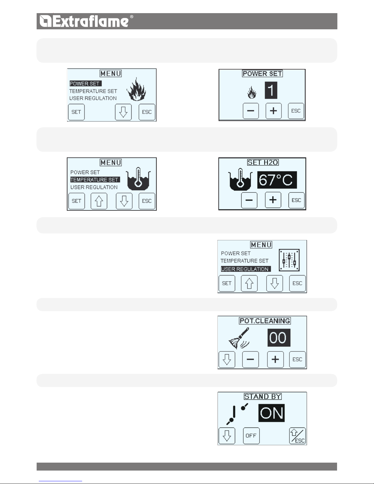
71ENGLISH
SET POWER
The following menu allows to set the power. Minimum power 1, maximum power 5.
SET TEMPERATURE
The following menu allows the boiler temperature to be set. Possible setting are: 65 - 80°C.
USER REGULATION
The USER REGULATION allows you to:
Adjust the frequency of the BURNING POT CLEANING
Enable / disable the STAND BY
Enable / disable the CHRONO
Adjust the PELLET in percentage.
• BURN POT CLEANING
The menu allows to increase the frequency of the automatic
cleaning of the brazier. (Range 0-50)
• STAND BY
The Stby function is used if immediate generator switch-o or
modulation via an additional thermostat.
71

72 ENGLISH
• ENABLE CHRONO
It allows to enable/disable the chrono and the various time slots of the boiler.
• PELLET REGULATION
The following menu allows to adjust the percentage of pellet
feed.
If the generator has operating problems due to the quantity of
pellets, you can adjust the pellet load directly from the control
panel.
Problems related to fuel quantity can be divided into 2
categories:
FUEL SHORTAGE:
the generator never manages to develop an adequate ame, tending to remain very low even at high power.
at minimum power the generator tends to almost switch-o taking the generator into “NO PELLETS” alarm.
when the generator displays the alarm for “
NO PELLETS
” there may be non-burnt pellet inside he brazier.
EXCESS FUEL:
the
generator
develops a very high ame even at low power.
the panoramic glass tends to get very dirty, almost completely darkening it.
the burn pot tends to become encrusted, blocking the holes for air intake due to the excessive pellet feed, as it is only
burned partially.
The adjustment to be performed is in percentage. Therefore a modication of this parameter will lead to a proportional variation
of all
generator
feeding speeds.
Feeding is from -30% to +20%.
STATUS
References reserved to the technician
USER MENU
The USER MENU allows you to:
Set date and time (See chapter before ignition)
Set the programming CHRONO
Set the LANGUAGE
Set the DISPLAY
Use the RESET
72

73ENGLISH
RECOMMENDATIONS EXAMPLE
The ignition and switch-o times must be within the arc of
one day, from 0 to 24 and not over several days:
Before using the chrono function, set the current day and
time. Therefore check that the points listed in the “Set
clock” sub-chapter have been followed, so that the chrono
function works. As well as programming it, activate it as
well.
Switch-on time 07:00
CORRECT
Switch-o time 18:00
Switch-on time 22:00
INCORRECT
Switch-o time 05:00
• CHRONO
The chrono allows to program 4 time spans within a day to use
every day of the week.
The switch-on and switch-o time can be set in every time
slot, along with the days of use of the programmed time slot
and the desired water temperature (65 - 80°C).
TO ENABLE THE CHRNONO, FOLLOW THE INSTRUCTIONS
DESCRIBED IN "ENABLE CHRONO" CHAPTER
Ignition hour
Shutdown hours:
Temperature set
Days enabled
R
Days not enabled
1 = Monday
2 = Sunday
Forward
Back
Setting
• LANGUAGE
(See chapter before ignition)
• DISPLAY
- Buzzer
- Brightness
- Contrast
The Display menu allows you to:
Enable / disable the buzzer.
Adjust the brightness of the display
Adjust the contrast of the display
73

74 ENGLISH
BUZZER
When set to "OFF" the acoustic signal is disabled.
BRIGHTNESS
It allows you to adjust the backlight of the display.
The possible settings range from OFF - 10 to 30.
Activating OFF, the back light of the display will go o after a
preset delay.
The back light will go on as soon as a key is pressed or if an
alarm should be triggered in the machine.
CONTRAST
Allows you to change the display contrast.
(Range from 2-50)
• RESET
Allows to reset all values modiable by the user to the
default values.
OTHER FUNCTIONS
AIR DISCHARGE
This function allows to bleed any air in the thermal-product. (For 15 minutes the pump operates alternately, 30 seconds on and
30 seconds o)
To activate the function:
With the generator cold and in "OFF" state press
and then "AIR" for 5 secs.
To stop the "air Bleeding function press the button
FIRST LOAD
This function allows to activate the pellet feeding motor reducer
for continuous functioning.
To activate the function:
With the generator cold and in "OFF" state press
and then
"LOAD" for 5 secs.
To stop the "First load" press the key
COMBUSTION CHAMBER CLEANING
This feature allows you to open the bottom brazier, facilitating the cleaning of the combustion chamber.
To activate the function:
With the generator cold and in "OFF" state press and subsequently for 5 sec.
With the ash hook supplied as standard scrape the walls of the combustion chamber and transfer the residual ash in the
brazier room a into the ash tray.
After
cleaning, press and hold the button
.
OPEN THE DOOR ONLY WHEN THE OPERATION IS PERFORMED! THE DISPLAY WILL INDICATE THE SUCCESSFUL OPENING!
AIR DISCHARGEFIRST LOAD
CLEANING
74

ENGLISH
CLEANING AND MAINTENANCE
For proper operation, the generator must undergo routine maintenance carried out by a qualied technician, at least once a
year. Inspection and maintenance activities must be performed by specialized technicians who are familiar with the instructions
in this manual.
ALWAYS FOLLOW THE INSTRUCTIONS IN MAXIMUM SAFETY CONDITIONS!
Make sue the power cable is unplugged since the generator could be programmed to start.
That the generator is cold in its entirety.
The ashes are completely cold.
Ensure an eective exchange of air in the room during the cleaning of the product.
A poor cleaning is detrimental to the proper functioning and safety!
IF THE POWER SUPPLY CABLE IS DAMAGED, IT MUST BE REPLACED BY THE AFTERSALES SERVICE OR BY
A SIMILARLY QUALIFIED PERSON, SO AS TO AVOID ALL RISKS.
EVERY YEAR MAKE THE EXHAUST FUMES, SMOKE DUCTS AND "T"FITTINGS, INCLUDING CAPS AND
INSPECTION DOORS BE CLEANED IF ANY CURVES AND ANY HORIZONTAL SECTIONS!
THE CLEANING OF THE GENERATOR FREQUENCY IS APPROXIMATE! THEY DEPEND ON THE QUALITY OF
THE PELLETS USED AND THE FREQUENCY OF USE.
IT CAN HAPPEN THAT THESE OPERATIONS SHOULD BE PERFORMED MORE FREQUENTLY.
CLEANING AND MAINTENANCE BY THE USER
The cleaning process should be borne by the user of the generator and must be done by paying maximum attention after
reading the information on the procedures described in this manual.
MAINTENANCE OF SURFACES AND COAT ING
The surface cleaning must take place when both the generator and the coating are completely cold. For the maintenance of
surfaces and metal parts, simply use a damp cloth with water or mild soap and water.
Never use abrasive cleaning agents or aggressive solvents for cleaning! Failure to observe the instructions may damage the
surface of the generator.
CLEANING THE CERAMIC GLASS
The cleaning of the ceramic glass is allowed only when the latter is completely cold. Clean the ceramic glass surface using a dry
brush or in the case of a very dirty surface a specic detergent by sprinkling a small amount on a cloth and then passing it on
the ceramic glass.
Do not spray cleaner or any other liquid directly on the glass or on the gaskets.
CLEANING THE TANK PELLETS
When the tank empties completely, unplug the power cord from the generator and remove residues (dust, chips, etc..) from the
tank empty, before lling it.
ROUTINE MAINTENANCE
In order to guarantee proper functioning and safety of the device, the operations indicated below must be performed every
season or more often when necessary.
DOOR, ASH DRAWER AND BRAZIER GASKETS
The gaskets ensure the tightness of the
generator
and its resulting good operation.
It is necessary that they are checked periodically and if worn or damaged they must be replaced immediately.
These operations must be carried out by a qualied technician.
75

ENGLISH
WEEKLY COMBUSTION CHAMBER AND THE
ASH TRAY:
It is recommended to remove the ash in the combustion
chamber at least once a week using a suitable vacuum
cleaner.
To facilitate cleaning, we recommend the activation of the
"CLEAN COMBUSTION CHAMBER" See chapter a OTHER
FUNCTIONS.
Empty the ash drawer every week or when required.
DAILY SCRAPERS:
HSYSTEM 15/22: The heat exchangers must only be cleaned
when the generator is cold! Cleaning the heat exchangers
allows to ensure constant heat output over time. This type of
maintenance must be performed at least once a day. To do
this, just use the relevant scrapers positioned in the upper
part of the generator, making
the upward movements and
vice versa several times.
HSYSTEM 30: The cleaning of the heat exchangers is carried
out automatically using a mechanical system that allows to
guarantee over time constant heat output.
DAILY BRAZIER:
Through a mechanical system, the burn pot is cleaned at set intervals automatically by the boiler. In the picture below one
can see the burn pot with the opening underneath it.
It is in any case recommended to remove any ash residue using a vacuum cleaner, at least once every 2 days.
76

D
E
A
C
C
HP15 - 22
C
HP30
ENGLISH
J
A CLEAN BRAZIER ENSURES SUCCESSFUL OPERATION!
KEEPING THE BRAZIER AND ITS HOLES A LWAYS THOROUGHLY
CLEAN FROM ANY RESIDUE FROM THE COMBUSTION, GUARANTEES
EXCELLENT COMBUSTION OF THE GENERATOR OVER TIME, TO AVOID
ANY MALFUNCTIONS THAT MAY REQUIRE THE INTERVENTION OF THE
TECHNICIAN.
IT IS POSSIBLE TO USE THE FUNCTION IN THE USER MENU
"ADJUSTMENT SET PELLET LOAD TO ADJUST COMBUSTION BASED
ON THE DESCRIBED REQUIREMENTS.
BURN POT
HOLES
ROUTINE MAINTENANCE
C
Combustion chamber & heat exchanger (full
cleaning) and ignition plug duct cleaning
D
Tank (complete emptying and cleaning).
E
Air intake pipe inspection and of ow sensor
cleaning
A
Fumes motor (disassembly and cleaning and fumes
pipe and "T"), new silicone in required points
B
Inspections of gaskets, ash drawer and door
(replace them and apply silicone where required)
THE IMAGES SHOWN ARE FOR ILLUSTRATIVE PURPOSES ONLY
77

C
D
B
B
D
C
E
A
HP30
HP15 - 22 - 30
ENGLISH
C
Combustion chamber & heat exchanger (full
cleaning) and ignition plug duct cleaning
D
Tank (complete emptying and cleaning).
E
Air intake pipe inspection and of ow sensor
cleaning
A
Fumes motor (disassembly and cleaning and fumes
pipe and "T"), new silicone in required points
B
Inspections of gaskets, ash drawer and door
(replace them and apply silicone where required)
ROUTINE MAINTENANCE
THE IMAGES SHOWN ARE FOR ILLUSTRATIVE PURPOSES ONLY
78

ENGLISH
DISPLAYS
DISPLAY REASON
OFF
Generatore
spento
START
The start-up phase is in progress
PELLET FEEDING
Continuous pellet feeding is in progress during the ignition phase
IGNITION
The ignition phase is in progress
STARTUP
The start-up phase is in progress
WORK
The normal work phase is in progress
MODULATION
The stove is working at minimum
BURNING POT
CLEANING
Automatic burn pot cleaning is in progress
BURNING POT
CLEANING VACUUM
It's going to clean the brazier - insucient cause depression.
FINAL CLEANING
The nal cleaning is in progress
STAND BY
Stove o waiting for re-ignition due to an external thermostat
The stove will only re-start when the external thermostat makes a request
WAITING COOLING
A new ignition is attempted when the generator has just been switched o when the generator switches o, it
is necessary to wait for the complete shutdown of the engine smokes, then clean the burn pot.
The stove can
only be re-ignited when these operations have been performed.
HOFF
Stove o due to water temperature over set
As soon as the water temperature drops below the pre-set parameters, the stove will switch back on
WAITING BLACK OUT
The stove is cooling after a power cut.
Once cooling is completed it will re-start automatically
ANTIFREEZE
The anti-freeze function is in progress as the H2O t° is below the factory set threshold
the pump is active until the water reaches the pre-set factory parameter +2°C
ANTILOCK
The pump antilock function is in progress (only if the stove has been in an OFF state for at least 96 hours);
the pump is activated for the time pre-set by the manufacturer, in order to prevent it from blocking
AUTO BLOW
The automatic blow is active
EXCHANGER BLOCKED
The cleaning of the heat exchanger is blocked
ALARMS
DISPLAY EXPLANATION RESOLUTION
Indicates the presence of an alarm.
On: indicates the presence of an alarm
Flashing: indicates the deactivation of the depression
sensor.
The alarm can be reset by pressing key 1 for 3 seconds only
if the fumes motor has stopped and if 15 minutes have
elapsed from when the alarm was displayed.
79

ENGLISH
FUME MOTOR KO
Fumes motor fault Contact after-sales centre
FUMES PROBE
Fumes probe failure. Contact after-sales centre
HOT FUMES
High ue gas temperature
Check pellet feed (see “Pellet feed adjustment”). If the problem
cannot be solved, contact an authorised technician.
EMPTY TANK
The door is not closed correctly.
The ash drawer is not closed correctly.
The combustion chamber is dirty.
The ue exhaust pipe is blocked.
Check for the presence of pellets in the pellet tank
Check hermetic door closure.
Check hermetic closure of the ash drawer.
Check cleanliness of the fumes pipe, of the sensor in the
primary air channel and the combustion chamber.
Contact after-sales centre
NO IGNITION
The pellet feed-box is empty.
Pellet feed calibration inadequate.
Check for the presence of pellets in the feed-box.
Adjust the pellet ow (see “Pellet feed adjustment”).
Check the procedures described in the “Ignition” chapter.
NO IGNITION BLACK
OUT
No current during the ignition phase.
Set the
generator
to OFF though the button 1 and repeat the
procedures described in Chapter "Ignition".
NO PELLETS
The pellet feed-box is empty.
No pellet feed.
The motor reducer does not feed pellets.
Adjust the pellet ow (see “Pellet feed adjustment”).
WARNING VACUUM
The door is not closed correctly.
The ash drawer is not closed correctly.
The combustion chamber is dirty.
The ue exhaust pipe is blocked
Check hermetic door closure.
Check hermetic closure of the ash drawer.
Check cleanliness of the fumes pipe and the combustion
chamber.
PRESSURE SENSOR
DAMAGED
Flow sensor faulty.
Sensor disconnected
Pressure sensor faulty
Contact after-sales centre
OVERTEMPERATURE
H2O
The water in the
generator
has exceeded 95°C.
Possible air in the system.
Lack of adequate circulation.
Lack of or inadequate safety zone.
Possible circulator anomaly.
Contact after-sales centre
TRAPDOOR BLOCK
The automatic door of the brazier
is blocked.
Contact the after-sales centre
H2O MIN PRESSURE
The system pressure read by the pressure
switch is too low.
Presence of air in the system:
Possible lack of water or leaks due to
anomalies in some system component.
Contact the after-sales centre
WATER PROBE
H2O probe failure Contact the after-sales centre
H2O MAX PRESSURE
The pressure of the water has exceeded
the max threshold
Check that the expansion vessels are not damaged or
under-dimensioned
Check that the cold system is loaded at the correct pressure
COMMAND AUGER
Anomalous functioning
of pellet feeding
Contact the technical support
AUGER BLOCKED
Anomalous functioning
pellet engine
Contact the technical support
SANITARY TANK PROBE
Faulty boiler probe Contact the after-sales centre
BUFFER PROBE
Faulty boiler probe Contact the after-sales centre
80

HP 15 HP 22 HP 30
FRANCAIS
CARACTÉRISTIQUES TECHNIQUES
CARACTÉRISTIQUES
Poids kg 250 260 350
Hauteur mm 1304 1304 1408
Largeur mm 560 560 780
Profondeur mm 685 785 775
Diamètre du tuyau d'évacuation des fumées mm 120 120 120
Diaètre du tuyau d'aspiration de l'air mm 50 50 60
Puissance thermique globale maxi kW 16,9 25 33,9
Puissance thermique utile maxi (rendue à l'eau) kW 15,2 22,5 31
Puissance thermique globale min. kW 5 7,4 9,5
Puissance thermique utile min. kW 4,4 6,6 8,6
Consommation horaire du combustible maxi kg/h 3,5 5,2 7
Consommation horaire du combustible min. kg/h 1 1,5 2
Capacité du réservoir à pellet kg 43 60 71
Tirage de la cheminée conseillé mbar 0,03-0,1 0,03-0,1 0,03-0,1
Puissance électrique nominale W 450 450 450
Puissance électrique à Q
MIN W 140 140 160
Puissance électrique à Q
N W 180 180 200
Puissance en stand By W 3,5 4,0 4,0
Tension nominale Vac 230 230 230
Fréquence nominale Hz 50 50 50
Diamètre du tuyau entrée/sortie eau “ 1 1 1
Diamètre du tuyau d'évacuation automatique “ 1/2 1/2 1/2
Hauteur d'élévation de la pompe m 5 5 5
Pression hydraulique d'exercice maxi admise bar 2,5 2,5 2,5
Pression hydraulique d'exercice min. admise bar 0,6 0,6 0,6
Température des fumées à puissance réduite °C 56.5 62.7 63
Température des fumées à puissance nominale °C 103 136 122
Débit des fumées puissance réduite kg/s 0,0055 0,0065 0,0081
Débit des fumées puissance nominale kg/s 0,0128 0,0164 0,0194
Classe chaudière 5 5 5
Période de combustion h 12 12 10
Champ de réglage thermostat de l'eau °C 65-80 65-80 65-80
Température minimale retour de l'eau °C 55 55 55
Rendement direct à puissance nominale % >90 >90 91,4
Bruit
*
dB 40 40 40
* Valeur relevée dans la chambre anéchoïque avec l'appareil fonctionnant à puissance nominale.
81

A
B
C
D
D
F
E
F
E
G
G
H
H
I
I
J
J
HP30
HP 15 - 22
FRANCAIS
HP 15
FLUX D'EAU
(kg/h)
RÉSISTAN CE
CÔTÉ EAU
(mbar)
Saut de température correspondant
T = 10K 1312 160
T = 20K 656 40
HP 22
FLUX D'EAU
(kg/h)
RÉSISTAN CE
CÔTÉ EAU
(mbar)
Saut de température correspondant
T = 10K 1938 367
T = 20K 969 92
HP 30
FLUX D'EAU
(kg/h)
RÉSISTAN CE
CÔTÉ EAU
(mbar)
Saut de température correspondant
T = 10K 2668 687
T = 20K 1334 172
IDENTIFICATION DES COMPOSANTS
A Écran
B Couvercle du réservoir à pellet
C Porte
D Prise d'alimentation pour câble électrique
E Thermostat de sécurité (réarmement manuel) 100°C
F Thermostat de sécurité (réarmement manuel) 85°C
G Tuyau d'évacuation des fumées de combustion
H Tuyau d'aspiration de l'air pour la combustion
I Interrupteur principal de démarrage
J Port sériel
82

FRANCAIS
INTRODUCTION
Les générateurs produits dans nos usines sont fabriqués en faisant aussi attention à chaque élément an de protéger aussi bien
l'utilisateur que l'installateur contre tout éventuel accident. Nous recommandons donc au personnel technique agréé de veiller
tout particulièrement, après chaque intervention eectuée sur le produit, aux branchements électriques, surtout en ce qui
concerne la partie dénudée des conducteurs, qui ne doit jamais dépasser du bornier, an d’éviter tout contact avec les parties
vives du conducteur.
Ce manuel d’instructions fait partie intégrante du produit : s’assurer qu’il accompagne toujours l’appareil, y compris en cas de
cession à un autre propriétaire ou utilisateur, ou en cas de nouvelle installation, dans un autre emplacement. Si ce manuel devait
être abîmé ou perdu, en demander un autre exemplaire au service d’Assistance Technique le plus proche.
Ce générateur doit être destiné à l’utilisation pour laquelle il a été expressément réalisé. Toute responsabilité contractuelle ou
extracontractuelle du fabricant, en cas de dommages causés à des personnes, animaux ou choses, dus à des erreurs d’installation,
de réglage, d’entretien et d’utilisation incorrects, est exclue.
INSTALLATION
L’installation du générateur et des équipements auxiliaires relatifs à l’installation de chauage, doit être conforme à toutes les
normes et aux réglementations actuelles et aux conditions prévues par la loi. L'installation doit être eectuée par du personnel
autorisé, qui devra remettre à l'acheteur une déclaration de conformité de l'installation, fournir les instructions nécessaires pour
l’utilisation initiale et s’assumer toute la responsabilité en garantissant le bon fonctionnement du produit installé.
Il faut également respecter toutes les lois et réglementations nationales, régionales, provinciales et communales existants dans
le pays où a été installé l’appareil.
En cas de non respect de ces précautions, le fabricant ne s'assumera aucune responsabilité. Avant de procéder à l'installation,
nous conseillons de laver soigneusement toutes les tuyauteries de l'installation an d'éliminer les éventuels résidus qui
pourraient compromettre le bon fonctionnement de l'appareil. Pendant l'installation, il faut informer l'utilisateur que:
a. En cas de perte d'eau, il faut fermer l'alimentation hydrique et prévenir avec insistance le service d'Assistance technique.
b. La pression d'exercice de l'installation doit être contrôlée périodiquement.En cas d’inutilisation prolongée du générateur,
nous conseillons l'intervention du service d'assistance technique pour eectuer au moins les opérations suivantes :
- Placer l'interrupteur général en position 0.
- Fermer les robinets d'eau des installations thermique et sanitaire.
- En prévision du gel, vider l'installation thermique et sanitaire.
PREMIÈRE MISE EN MARCHE
Après avoir enlevé l’emballage, s’assurer que le contenu est intact et qu’il ne manque rien.
Le cas échéant, s'adresser au revendeur auprès duquel l’appareil a été acheté.
Lors de la première mise en service de l'appareil, vérier que tous les dispositifs de sécurité et de contrôle qui constituent le générateur
fonctionnent correctement. Tous les composants électriques qui constituent le générateur, tout en garantissant le fonctionnement
correct, devront être remplacés par des pièces originales et exclusivement par un centre d'assistance technique agréé.
Avant de partir, le personnel préposé à la première mise en service devra contrôler le fonctionnement du générateur pendant au
moins un cycle complet de travail. La maintenance du générateur doit être eectuée au moins une fois par an en la programmant
à l'avance au service d'assistance technique.
RÉGLEMENTATIONS
Les chaudières ont été conçues et réalisées conformément aux réglementations suivantes :
UNI EN 303-5 Chaudières pour chauage. Chaudières pour combustibles solides, avec alimentation manuelle et
automatique, ayant une puissance thermique nominale allant jusqu'à 500 kW
DIRECTIVES
2004/108/CE : directive CEM
2006/95/CE : directive basse tension
2006/42/CE : directive machines
2011/65/EU : directive ROHS 2 »
POUR LA SÉCURITÉ
L’utilisation du générateur par des enfants ou des personnes handicapées est strictement interdite.
Ne pas toucher le générateur si vous êtes pieds nus et avec des parties du corps mouillées ou humides.
Interdiction de toucher aux dispositifs de sécurité ou de réglage, sans l’autorisation ou les indications du fabricant.
83

A
F
A
B
D
E
C
FRANCAIS
Ne pas tirer, enlever, tordre les câbles électriques qui sortent du générateur, même si ce dernier n’est pas branché au
réseau d’alimentation électrique.
Eviter de boucher ou obstruer les ouvertures d’aération du local d’installation.
Les ouvertures d'aération sont indispensables pour une combustion correcte.
Ne pas laisser les éléments de l'emballage à la portée des enfants ou de personnes handicapées, non assistés.
Lorsque l'appareil est en état de marche, la porte du foyer doit toujours rester fermée.
Eviter tout contact direct avec les parties de l’appareil qui, lors du fonctionnement, peuvent devenir brûlantes.
Contrôler la présence éventuelle d’obstructions avant d’allumer un appareil après une longue période d’inactivité.
Le générateur a été conçu pour fonctionner dans n’importe quelle condition climatique (même critique) en cas de
conditions particulièrement défavorables (vent fort, gel) les systèmes de sécurité pourraient se déclencher en provoquant
l’arrêt du générateur.
Si cela se vérie, contacter le Service d’Assistance Technique et surtout ne pas désactiver les systèmes de sécurité.
En cas d'incendie du conduit de fumée, se munir d'extincteurs pour étouer les ammes ou appeler les pompiers.
Il faut contacter le service d'assistance technique si l'éventuel blocage du générateur, mis en évidence sur l'écran, ne
dépend pas d'une maintenance ordinaire non eectuée.
CES CHAUDIÈRES DOIVENT ÊTRE UTILISÉES POUR CHAUFFER L'EAU À UNE TEMPÉRATURE QUI NE DÉPASSE
PAS CELLE D'ÉBULLITION MENTIONNÉE DANS LES CONDITIONS D'INSTALLATION.
DISTANCES CONSEILLÉES POUR COMPARTIMENT CHAUDIÈRE
Ci-dessous, quelques images illustrant les distances minimales exigées dans la pièce destinée à la chaudière.
L'entreprise recommande de respecter ces mesures.
RÉFÉRENCES OBJETS NON INFLAMMABLES RÉFÉRENCES OBJETS NON INFLAMMABLES
A 500 mm D 300 mm
B 1000 mm E > 100 cm
2
C 1000mm F 230cm
84

FRANCAIS
MISES EN GARDE
Ce manuel d'instructions fait partie intégrante du produit: s'assurer qu'il soit toujours avec l'appareil, même en cas de cession
à un autre propriétaire ou utilisateur, ou en cas de transfert à un autre emplacement. Si ce manuel devait être abîmé ou perdu,
en demander un autre exemplaire au service technique le plus proche. Ce produit doit être réservé à l'usage pour lequel il a
expressément été réalisé. Toute responsabilité contractuelle et extracontractuelle du fabricant, en cas de dommages causés à
des personnes, animaux ou biens, dus à des erreurs d’installation, de réglage, d’entretien et d’utilisation incorrects, est exclue.
L'installation doit être exécutée par du personnel qualié et autorisé, qui assumera toute la responsabilité de
l'installation dénitive ainsi que du bon fonctionnement ultérieur du produit installé. Il faut respecter toutes les lois et
règlementations nationales, régionales, provinciales et communales existant dans le pays où a été installé l’appareil,
ainsi que les instructions contenues dans le présent manuel.
En cas de non respect de ces précautions, le fabricant n'assume aucune responsabilité.
Après avoir enlevé l’emballage, s’assurer que le contenu est intact et qu’il ne manque rien. Le cas échéant, s'adresser au revendeur
auprès duquel l’appareil a été acheté.
Toutes les pièces électriques qui composent le produit et qui garantissent son bon fonctionnement, devront être remplacées
par des pièces d'origine et uniquement par un Centre d'Assistance Technique agréé.
SÉCURITÉ
L'utilisation du générateur par des personnes (y compris les enfants) ayant des capacités physiques, sensorielles et
mentales réduites, ou des personnes inexpérimentées est interdite à moins qu'une personne responsable de leur sécurité ne
les surveille et les instruise.
Les enfants doivent être contrôlés pour s'assurer qu'ils ne jouent pas avec l'appareil.
Ne pas toucher le générateur nu-pieds ou avec d'autres parties du corps mouillées ou humides.
Interdiction de toucher aux dispositifs de sécurité ou de réglage, sans l’autorisation ou les indications du fabricant.
Ne pas tirer, débrancher ou tordre les câbles électriques qui sortent du poêle, même si celui-ci n’est pas branché au réseau
d’alimentation électrique.
Il est recommandé de positionner le câble d'alimentation de façon à ce qu'il n'entre pas en contact avec les parties chaudes
de l'appareil.
La che d'alimentation doit être accessible après l'installation.
Éviter de réduire les dimensions ou d'obstruer les ouvertures d'aération de la pièce d'installation. Les ouvertures d'aération
sont indispensables pour une combustion correcte.
Ne pas laisser les éléments de l'emballage à la portée des enfants ou de personnes handicapées, non assistés.
Lorsque l'appareil est en état de marche, la porte du foyer doit toujours rester fermée.
Quand l'appareil fonctionne, il est chaud au toucher, en particulier toutes les surfaces extérieures; il est donc recommandé
de faire attention.
Contrôler la présence éventuelle d’obstructions avant d’allumer un appareil après une longue période d’inactivité.
Le générateur a été conçu pour être utilisé dans n’importe quelle condition climatique (même critique). Cependant, en cas
de climat particulièrement défavorable (vent fort, gel), les systèmes de sécurité pourraient se déclencher, provoquant ainsi l’arrêt
du générateur. Si cela se vérie, contacter le Service d’Assistance Technique et surtout ne pas désactiver les systèmes de sécurité.
En cas d'incendie du conduit de fumée, se munir d'extincteurs pour étouer les ammes ou appeler les pompiers.
Cet appareil ne doit pas être utilisé comme incinérateur de déchets.
N'utiliser aucun liquide inammable pour l'allumage
Au cours du remplissage, veiller à ce que le sac de pellets n'entre pas en contact avec l'appareil.
Les faïences sont des produits artisanaux et en tant que tels, elles peuvent présenter des micro-grumeaux, des craquelures
et des imperfections chromatiques. Ces caractéristiques en démontrent la valeur. Étant donné leur coecient de dilatation
diérent, l'émail et la faïence produisent des micro-ssures (craquelures) qui témoignent de leur authenticité. Pour nettoyer
les faïences, nous conseillons d'utiliser un chion doux et sec. Si un détergent ou du liquide est utilisé, ce dernier pourrait
pénétrer à l'intérieur des ssures et les mettre en évidence.
ENTRETIEN ORDINAIRE
Selon le décret du 22 janvier 2008 n°37 art.2, l'expression «entretien ordinaire» dénit les interventions ayant pour but de
contenir la dégradation normale d'usage, et d'aronter les événements accidentels qui comportent la nécessité de premières
interventions, qui ne modient cependant pas la structure de l'installation sur laquelle on intervient, ou sa destination d'usage
selon les prescriptions prévues par la règlementation technique en vigueur et le manuel d'utilisation et d'entretien du fabricant.
85

FRANCAIS
INSTALLATION HYDRAULIQUE
Ce chapitre décrit quelques concepts qui font référence à la norme italienne UNI 10412-2 (2009).
Comme déjà indiqué précédemment, lors de l’installation, il faudra respecter toutes les normes éventuelles aussi bien nationales
que régionales, départementales et communales en vigueur dans le pays où l’appareil sera installé.
Pendant l'installation du poêle il est OBLIGATOIRE d'insérer sur l'installation un manomètre pour la visualisation de la pression de
l'eau.
INSTALLATION ET DISPOSITIFS DE SÉCURITÉ
L'installation, les raccordements de l'installation, la mise en service et la vérication du fonctionnement correct devront être eectués
dans les règles de l'art, dans le respect total des normes en vigueur, aussi bien nationales que régionales, ainsi que de ces instructions.
Pour l'Italie, l'installation doit être eectuée par du personnel professionnellement autorisé (DM 22 janvier 2008 n°37).
Le fabricant décline toute responsabilité quant aux dommages aux biens et/ou aux personnes provoqués par l'installation.
DISPOSITIFS DE SÉCURITÉ POUR INSTALLATION À VASE FERMÉ
Selon la norme UNI 10412-2 (2009) en vigueur en Italie, les installation fermées doivent être dotées de : une soupape de sécurité,
un thermostat de commande du circulateur, un thermostat d'activation de l'alarme acoustique, un indicateur de température, un
indicateur de pression, une alarme acoustique, un interrupteur thermique automatique de régulation, un interrupteur thermique
automatique de blocage (thermostat de blocage), un système de circulation, un système d'expansion, un système de dissipation
de sécurité incorporé au générateur avec une vanne de décharge thermique (à actionnement automatique), si l'appareil n'est pas
équipé d'un système de régulation automatique de la température.
DISTANCES DES DISPOSITIFS DE SÉCURITÉ CONFORMÉMENT À LA NORMATIVE
Les capteurs de sécurité de la température doivent se trouver sur la machine ou à une distance de 30 cm maximum du raccordement
de refoulement
.
Dans le cas où les générateurs seraient dépourvus de tous les dispositifs, ceux manquants peuvent être installés sur la tuyauterie
TABLEAU DES DISPOSITIFS POUR INSTALLATION À VASE CLOS PRÉSENTS ET NON PRÉSENTS À BORD DU PRODUIT
Vane de sécurité
R
Thermostat de commande du circulateur (il est géré par la sonde eau du programme carte)
R
Thermostat d’activation de l’alarme acoustique
Indicateur de la température de l’eau (acheur)
R
Transducteur de pression avec visualisation sur l’acheur
R
Alarme acoustique
Interrupteur thermique automatique de réglage (géré par le programme carte)
R
Transducteur de pression avec alarme pressostat minimale et maximale
R
Interrupteur thermique automatique de blocage (thermostat de blocage) échauement limite de l'eau
R
Système de circulation (pompe)
R
Système d’expansion
R
86

FRANCAIS
de refoulement du générateur, à une distance maximale de 1 m. de la machine.
COMPOSANT DISTANCE
Capteurs de sécurité de la température Sur la machine ou non supérieure à 30 cm
Dispositifs manquants parce qu'ils ne sont pas fournis de série Non supérieure à un mètre, sur le tube de refoulement
Les appareils pour le chauage à usage domestique à chargement automatique doivent: être dotés d'un thermostat de
blocage du combustible ou être dotés d'un circuit de refroidissement prédisposé par le fabricant de l'appareil.
Le circuit de refroidissement doit être activé par une soupape de sécurité thermique qui garantisse que la température limite
réglementée par la norme ne soit pas dépassée.
Le branchement entre le groupe d'alimentation et la vanne ne doit pas être sectionné.
La pression en amont du circuit de refroidissement doit être d'au moins 1,5 bar.
TYPOLOGIE D'INSTALLATION
Il existe 2 types diérents d'installations:
Installation à vase ouvert et installation à vase fermé.
Le produit a été projeté et réalisé pour travailler avec des installations à vase fermé.
INSTALLATION À VASE FERMÉ
Installation où l'eau contenue n'est pas en communication directe ou indirecte avec l'atmosphère. En général, l'installation à
vase fermé est dotée d'un des dispositifs d'expansion suivants:
Vase d'expansion fermé préchargé, avec membrane imperméable au passage des gaz.
Système d'expansion fermé automatique avec compresseur et membrane imperméable au passage des gaz.
Système d'expansion fermé automatique, avec pompe de transfert et membrane imperméable au passage des gaz.
Système d'expansion sans diaphragme.
GÉNÉRALITÉS
Les installations fermées doivent être dotées de:
Soupape de sécurité
Thermostat de commande du circulateur
Thermostat d'activation de l'alarme acoustique
Indicateur de température
Indicateur de pression
Alarme acoustique
Interrupteur thermique automatique de régulation
Interrupteur thermique automatique de blocage (thermostat de blocage)
Système de circulation
Système d'expansion
Système de dissipation de sécurité incorporé au générateur avec vanne de décharge thermique (à actionnement
automatique), si l'appareil n'est pas doté d'un système de régulation automatique de la température
SOUPAPES DE SÉCURITÉ
Le débit d’évacuation de la soupape de sécurité doit être tel qu’il puisse permettre l’évacuation d’une quantité de vapeur non
inférieure à : Q / 0,58 [kg/h] où Q est la puissance utile rendue à l'eau du générateur exprimée en kilowatt. Le diamètre de la
section transversale minimale nette de l’entrée de la soupape doit dans tous les cas ne pas être inférieur à 15 mm. La pression
d’évacuation de la soupape, égale à la pression d’étalonnage, augmentée de la surpression, ne peut dépasser la pression
maximum d’exercice du générateur de chaleur. Le concepteur du projet doit s’assurer que la pression maximale présente en
chaque point de l’installation ne dépasse pas la pression maximale d’exercice de chaque composant. La soupape de sécurité
doit être connectée à la partie la plus haute du générateur de chaleur ou à la tuyauterie de sortie, près du générateur. La
longueur de la section de tuyauterie comprise entre la connexion au générateur et la soupape de sécurité ne doit pas, dans
87

1
2
3
FRANCAIS
tous les cas, dépasser les 1 m. La tuyauterie de connexion de la soupape de sécurité au générateur de chaleur ne doit pas être
interceptable et elle ne doit présent en aucun point une section inférieure à celle d'entrée de la soupape de sécurité ou à la
somme des sections d'entrée dans le cas de plusieurs vannes à la tête d'un seul tuyau. La tuyauterie d’évacuation de la soupape
de sécurité doit être réalisée de façon à ne pas empêcher le fonctionnement normal et ne doit pas présenter un quelconque
risque aux personnes ; l'évacuation doit sortir le plus près possible de la soupape de sécurité et doit être accessible et visible.
Cependant, le diamètre de la tuyauterie d’évacuation ne doit pas être inférieur à celui du raccordement de sortie de la soupape
de sécurité. Le diamètre du raccordement de sortie est le diamètre intérieur minimum sur la sortie de la soupape en amont de
l'éventuel letage interne.
VASE D'EXPANSION FERMÉ
Mises en garde: vérier que la pression de précharge du vase d'expansion soit de 1.5 bar.
La pression maximale d’exercice du vase ne doit pas être inférieure à la pression de réglage de la soupape de sécurité à laquelle il faut additionner
la surpression caractéristique de la soupape elle-même, en considérant le dénivellement éventuel entre vase et soupape et la pression engendrée
par le fonctionnement de la pompe. La capacité du (ou des) vase(s) d’expansion est évaluée en fonction de la capacité totale du système mentionné
dans le projet. Les vases d’expansion fermés doivent être conformes aux dispositions pour les appareils à pression en matière de conception,
fabrication, évaluation de la conformité et utilisation. Sur la tuyauterie de raccordement, qui peut être constituée de portions d'installation, aucun
organe d'interception ne doit être introduit et aucune diminution de section ne doit être pratiquée. Il est permis d'insérer une vanne d'arrêt à trois
voies qui permette la connexion du vase avec l'atmosphère, lors d'opérations d'entretien. Ce dispositif doit être protégé contre les manœuvres
accidentelles. Le tuyau de raccordement doit être réalisé de façon à ne pas présenter de points d'accumulation d'incrustations ou de dépôts.
Dans le cas de plusieurs générateurs de chaleur alimentant un même système ou un même circuit secondaire, chaque générateur de chaleur doit
être connecté directement au vase d'expansion ou au groupe des vases d'expansion du système dimensionné dans l’ensemble pour le volume
total de l'eau contenue dans le même système et dans le même circuit indépendant. Lorsqu'il faut séparer le générateur de chaleur du vase
d’expansion ou du groupe de vases d’expansion, il faut utiliser un robinet à trois voies ayant les mêmes caractéristiques décrites précédemment,
sur la tuyauterie de connexion du générateur au vase employé de façon à assurer la connexion du générateur avec le vase d’expansion ou avec
l’atmosphère dans n’importe quelle position. Les vases d'expansion, les tuyauteries de raccordement, les tuyaux de purge et d'évacuation doivent
être protégés contre le gel si ce phénomène est probable. La solution adaptée dans ce but doit être décrite dans le projet.
CONTRÔLES AU PREMIER ALLUMAGE
Avant de raccorder la chaudière, prévoir:
a) un lavage soigné de toutes les tuyauteries de l'installation an d'enlever tout résidu éventuel qui pourrait compromettre le bon
fonctionnement de certains composants de l'installation (pompes, vannes, etc.).
b) un contrôle pour vérier que la cheminée ait un tirage adéquat, qu'elle n'ait pas d'étranglement et qu'aucune autre évacuation venant
d'autres appareils ne soit insérée dans le même tuyau d'évacuation des fumées.
Ceci pour éviter des augmentations de puissance non prévues. Uniquement après ce contrôle, il est possible de monter le raccord cheminée
entre la chaudière et le tuyau d'évacuation des fumées. Nous conseillons un contrôle des raccords avec les tuyaux d'évacuation des fumées
préexistants.
VANNE MÉLANGEUSE ANTICONDENSAT ION OBLIGATOIRE
Il est obligatoire de réaliser un circuit d’anti-condensation adéquat, qui garantit une température de retour de l’appareil d’au moins
55º C. La soupape anti-condensation, par exemple, peut être utilisée dans les chaudières à combustible solide car il prévient le
retour d’eau froide dans l’échangeur
Les liaisons 1 et 3 sont toujours ouvertes et, avec la pompe
installée sur le retour, elles garantissent la circulation de l'eau à
l'intérieur de l'échangeur de la chaudière à biomasse.
Une température de retour élevée permet d'améliorer le
rendement, réduit la formation de condensation des fumées et
prolonge la durée de vie du générateur.
Les vannes en commerce proposent diérents réglages,
le fabricant conseille d'utiliser le modèle 55°C avec des
raccordements hydrauliques de 1”.
Lorsque la température de réglage de la vanne est atteinte,
la liaison 2 s'ouvre et l'eau de la chaudière se dirige vers
l'installation par le refoulement.
Vanne en vente comme accessoire (en option)
88

T1
T2
T3
B
A
T1
T2
B
T3
A
1 2
3
SI
T
M
S
G
VB
VMTA
HP 30
HP 15/22
FRANCAIS
SCHÉMA DE BASE DE L'INSTALLATION HYDRAULIQUE
LÉGENDE
A Entrée de l'air comburant
B Sortie évacuation des fumées
T1 Décharge soupape de sécurité 3 bar
T2 Refoulement / sortie chaudière
T3 Retour / entrée chaudière
M Manomètre
T Thermomètre
G Groupe de remplissage
S Évacuation soupape de sécurité
SI Décharge de l'installation
VB Soupape d'équilibrage
VMTA Vanne mélangeuse thermostatique 55°C
IL EST RECOMMANDÉ DE CONSULTER LA MANUEL GABARITS PRÉSENT SUR LE SITE POUR OBTENIR PLUS
D'INFORMATIONS À PROPOS DES RACCORDEMENTS HYDRAULIQUES, D E L'A SPIRATION DE L'AIR / L'ÉVACUATION
DES FUMÉES ET DES DIMENSIONS SPÉCIFIQUES DU PRODUIT CONCERNÉ.
89

H
0
1
2
3
4
5
6
7
0 0,5 1 1,5 2 2,5 3
85°C
100°C
H
85°C
100°C
HP 30
HP15 - 22
0
1
2
3
4
5
6
7
0 0,5 1 1,5 2 2,5 3 3,5
HP15
HP22-30
FRANCAIS
POSITIONNEMENT DU POÊLE
Pour un fonctionnement correcte du produit, il est recommandé de le positionner à l'aide d'un niveau, de manière à ce qu'il soit
parfaitement horizontal.
Le graphique gurant ci-contre illustre le comportement du circulateur utilisé sur nos thermoproduits aux vitesses congurables.
Débit (m
3
/h)
Hauteur d'élévation (m)
RÉARMEMENTS
Les gures ci-dessous montrent les positions des réarmements du réservoir (85°C) et H2O (100°C). Il est conseillé de contacter
le technicien agréé en cas de déclenchement d'un des réarmements, pour en vérier la cause.
CARACTÉRISTIQUES
HSYSTEM 15HSYSTEM 22HSYSTEM
30
Contenu d'eau échangeur (I) du thermoproduit 32 32 66
Volume vase d'expansion intégré sur le thermoproduit (l)
8
* 8* 12*
Soupape de sécurité 3 bars intégrée sur le thermoproduit
P P P
Pressostat de minimum et de maximum intégré sur le thermoproduit
P P P
Circulateur intégré sur le thermoproduit
P P P
Hauteur d'élévation max. circulateur (m) 6 6 6
* PRÉVOIR UN ÉVENTUEL VASE D'EXPANSION SUPPLÉMENTAIRE SELON LE CONTENU D'EAU DE L'INSTALLATION
Débit (m
3
/h)
Hauteur d'élévation (m)
90

FRANCAIS
DISPOSITIFS
(sur les modèles prévus)
Microrupteur porte : Avec la porte ouverte, le fonctionnement du
système de nettoyage du brasier est bloqué
Pressostat électronique : en cas de dépression inadaptée, il met la
machine en alarme.
Fusible F 2.5 A 250 V (poêles) : il protège la machine contre les écarts
de courant violents
Bulbe mécanique réglé à 85°C à réarmement manuel : il agit en
bloquant le chargement de combustible si la température (t°) du
réservoir de pellet atteint la limite de 85°C. Le réarmement doit être
eectué par un personnel qualié et/ou l'assistance technique du
fabricant
Sonde de contrôle de température du réservoir à pellet : en cas de
surchaue du réservoir, la machine module automatiquement pour
revenir aux valeurs de température normales
Pressostat mécanique air : il bloque le pellet en cas de dépression
insusante
NORMES DE RÉFÉRENCE
L'installation doit être conforme à :
UNI 10683 (2012) Générateurs de chaleur alimentés au
bois ou avec d'autres combustibles solides :
Les cheminées doivent être conformes à :
UNI EN 13063-1 et UNI EN 13063-2, UNI EN 1457, UNI EN 1806
en cas de cheminées non métalliques :
EN 13384 méthode de calcul des caractéristiques thermo-
aérauliques des cheminées.
UNI EN 1443 (2005) cheminées : conditions générales.
UNI EN 1457 (2012) cheminées : conduits internes en terre
cuite et céramique.
UNI/TS 11278 cheminées (2008) Cheminées/ Conduits de
fumée/ Conduits/ Tuyaux d'évacuation métalliques.
UNI 7129 point 4.3.3 dispositions, règles locales et
prescriptions des Sapeurs Pompiers.
RÈGLEMENTATIONS NATIONALES, RÉGIONALES,
DÉPARTEMENTALES ET COMMUNALES
Il faut respecter toutes les lois et règlementations nationales,
régionales, provinciales et communales existant dans le pays où a
été installé l’appareil.
TERMES ET DÉFINITIONS
Aération : Renouvellement de l'air nécessaire pour éliminer les
produits de la combustion et pour éviter les mélanges ayant une
teneur dangereuse en gaz non brûlés.
Appareil à foyer fermé : Appareil prévu pour le fonctionnement
avec chambre de combustion fermée.
Appareil à tirage forcé : Appareil équipé de ventilation dans le
circuit de fumées et de combustion, avec refoulement des fumées
avec une pression positive par rapport au milieu.
Cheminée : Structure consistant en une ou plusieurs parois
contenant une ou plusieurs voies d'échappement.
Cet élément, dont la structure est surtout verticale, a pour but
d'expulser, à une hauteur convenable par rapport au
sol, les produits de la combustion.
Conduit de cheminée : Composant ou composants qui raccordent
la sortie du générateur de chaleur à la cheminée.
Pot de cheminée : Dispositif placé à l'embouchure de la cheminée,
permettant la dispersion des produits de la combustion, même en
présence de conditions atmosphériques défavorables.
Condensation : Produits liquides qui se forment lorsque la
température des fumées est inférieure ou égale au point de rosée
de l’eau.
Conduit pour tuyauterie : Conduit composé d'un ou plusieurs
élément(s) dont la structure est surtout verticale, adapté(s) de
façon spécique pour recueillir et expulser les fumées, et pour
résister dans le temps contre les composants et les éventuelles
condensations des fumées.
Il est adapté pour être inséré dans une cheminée, un compartiment
technique déjà présent ou neuf, même dans les nouveaux
bâtiments.
Installation étanche : Installation d'un appareil à fonctionnement
étanche, de façon à ce que tout l'air nécessaire à la combustion soit
prélevé de l'extérieur.
Maintenance : Ensemble des interventions nécessaires à garantir
dans le temps la sécurité et le fonctionnement, et à conserver
l'ecacité de l'installation selon les paramètres prescrits.
Système cheminée : Cheminée installée en utilisant une
combinaison de composants compatibles, fabriqués ou spéciés
par un seul fabricant dont la responsabilité du produit concerne
toute la cheminée.
Système d'évacuation des fumées : Installation pour l'évacuation
des fumées indépendante de l'appareil, constituée d'un canal de
fumée, d'une cheminée, d'une montée et d'un éventuel pot de
cheminée.
Zone de rayonnement : Zone immédiatement adjacente au foyer,
où se diuse la chaleur rayonnante provoquée par la combustion.
Zone de reux : Zone de l'extrados du toit où ont lieu des
surpressions ou dépressions pouvant inuencer la bonne
évacuation des produits de la combustion.
91

FRANCAIS
SCHÉMA DE FONCTIONNEMENT DES OPÉRATIONS
L'exécution dans les règles de l'art et le fonctionnement correct de l'installation comprennent une série d'opérations :
1. Activités préalables :
Vérication de l’adaptation de la puissance du générateur de chaleur en fonction des caractéristiques de l’installation;
vérication de l'adaptation de la pièce d'installation,
vérication de l'adaptation du système d'évacuation des fumées,
vérication de l'adaptation des prises d'air extérieur ;
2. Installation :
réalisation de la ventilation et raccordement aux prises d'air extérieur,
réalisation et raccordement au système d'évacuation des fumées,
montage et pose,
éventuels branchements électriques et hydrauliques,
pose de l'isolation,
essai d'allumage et de fonctionnement,
pose de nitions et revêtements ;
3. Remise de la documentation complémentaire ;
4. Contrôle et maintenance.
D'autres mesures peuvent être demandées selon les besoins spéciques des Autorités compétentes.
ACTIVITÉS PRÉALABLES
GÉNÉRALITÉS
Avant de procéder à toute opération de montage ou pose, il faut eectuer la vérication de compatibilité de l'installation,
des éventuelles limites disposées par des règlementations administratives locales, des prescriptions particulières ou
conventionnelles, dérivant d'un règlement de copropriété, domestique ou de lois ou actes administratifs.
Il faut notamment vérier l'adaptation :
des pièces d'installation ; la présence, dans les pièces d'installation et dans les pièces adjacentes et communicantes,
d'appareils déjà installés, même alimentés avec des combustibles diérents, en faisant particulièrement attention aux
installations non admises.
du système d'évacuation des fumées
des prises d'air externes
ADAPTATION DU SYSTÈME D'ÉVACUATION DES FUMÉES
L'installation doit être précédée d'une vérication de compatibilité entre l'appareil et le système d'évacuation des fumées, en
vériant les éléments suivants :
existence de la documentation de l'installation ;
existence et contenu de la plaquette de la cheminée ;
adaptation de la section interne de la cheminée ;
absence d'obstructions le long de toute la cheminée ;
hauteur et développement surtout vertical de la cheminée ;
existence et adaptation du pot de cheminée ;
distance de la paroi externe de la cheminée et du canal de fumée par rapport aux matériaux
combustibles ;
type et matériau de la cheminée ;
absence d'autres raccordements à la cheminée.
92

B
C
A
S
FRANCAIS
INSTALLATION
L'installation dans les pièces avec danger d'incendie est interdite. Il est également interdit d'eectuer l'installation à l'intérieur
de pièces à usage d'habitation (sauf pour les appareils à fonctionnement étanche) :
dans lesquelles se trouvent des appareils à combustible liquide à fonctionnement continu ou discontinu, qui prélèvent
l'air comburant dans la pièce où ils sont installés, ou bien
dans lesquelles se trouvent des appareils à gaz de type B destiné au chauage des pièces, avec ou sans production d'eau
chaude sanitaire, et dans les pièces adjacentes et communicantes, ou bien
dans lesquelles la dépression mesurée entre milieu extérieur et milieu intérieur serait supérieure à 4 Pa
Installations dans les salles de bain, chambres à coucher et studios
Dans les salles de bain, les chambres à coucher et les studios, seule l'installation étanche est permise, ou bien l'installation
d'appareil à foyer fermé, avec prélèvement canalisé de l'air comburant par l'extérieur.
Conditions de la pièce d'installation
Les plans d'appui et/ou les points de soutien doivent avoir une capacité portante pouvant supporter le poids global de l'appareil,
des accessoires et des revêtements de l'appareil.
Les murs adjacents latéraux et arrière, ainsi que le plan d'appui au sol, doivent être réalisés en matériau non combustible.
L’installation à proximité de matériaux combustibles ou sensibles à la chaleur est admise uniquement si une distance de sécurité
appropriée est interposée, qui pour les poêles à pellet est égale à :
RÉFÉRENCES OBJETS INFLAMMABLES OBJETS NON INFLAMMABLES
A 200 mm 100 mm
B 1500 mm 750 mm
C 200 mm 100 mm
Dans tous les cas, la température des matériaux combustibles adjacents ne doit pas atteindre une température supérieure ou
égale à la température ambiante augmentée de 65 °C.
Le volume minimum de la pièce où l'appareil est installé doit être supérieur à 15 m³.
INSTALLATION DES INSERTS
Lors de l’installation des inserts l’accès aux parties internes de l’appareil doit être interdit ainsi qu’aux parties sous tension lors
de l’extraction.
Les câblages éventuels, comme par exemple le câble d’alimentation ou les sondes ambiantes, doivent être positionnés de
manière à ne pas être endommagés pendant le mouvement de l’insert ou être en contact avec les parties chaudes.
Prise d'air
S= protection du sol
Conduit de
cheminée
Inspection
gure 1 gure 2
93

FRANCAIS
VENTILATION ET AÉRATION DES PIÈCES D'INSTALLATION
La ventilation est susante quand la pièce est équipée de prises d'air selon le tableau :
Prise d'air
Voir gure 2
Catégories d'appareils Norme de référence
Pourcentage de la section
nette d'ouverture par rapport à
la section de sortie des fumées
de l'appareil
Valeur minimale nette
d'ouverture du conduit de
ventilation
Poêles à pellet UNI EN 14785 - 80 cm²
Chaudières UNI EN 303-5 50% 100 cm²
Dans tous les cas, la ventilation est susante quand la diérence de pression entre milieu extérieur et milieu intérieur est
inférieure ou égale à 4 Pa.
En présence d'appareils à gaz de type B à fonctionnement intermittent, non destinés au chauage, il faut eectuer une ouverture
d'aération et/ou ventilation. Les prises d'air doivent répondre aux exigences suivantes :
être protégées par des grilles, grillages métalliques, etc., sans en réduire la section utile nette ;
être réalisées de façon à rendre possibles les opérations de maintenance ;
être placées de façon à ne pas pouvoir être bouchées ;
L'aux de l’air propre et non pollué peut être obtenu aussi d’une pièce adjacente à celle de l’installation (aération et ventilation
indirecte), pourvu que le ux puisse advenir librement à travers des ouvertures permanentes communicantes avec l’extérieur.
La pièce adjacente ne peut pas être utilisée comme garage, stock de matériau combustible ou autres activités comportant un
danger d'incendie, salle de bain, chambre à coucher ou pièce commune de l'immeuble.
SYSTÈME D'ÉVACUATION DES FUMÉES
CONDITIONS GÉNÉRALES
Le générateur de chaleur travaille en dépression et est équipé de ventilateur en sortie pour l’extraction des fumées .Chaque
appareil doit être raccordé à un système d'évacuation des fumées adéquat, et garantir une dispersion adéquate dans
l'atmosphère des produits de la combustion. L'évacuation des produits de la combustion doit avoir lieu par le toit. L’évacuation
directe par le mur vers des espaces fermés, même à ciel ouvert, est interdite.
Il n'est notamment pas permis d'utiliser des tuyaux métalliques souples extensibles.
La cheminée doit recevoir l'évacuation uniquement du canal de fumée raccordé à l'appareil. Les éléments suivants ne sont donc
pas admis : conduits de cheminée collectifs ; passage, dans la cheminée ou dans le canal de fumée, des évacuations de hottes
au-dessus des appareils de cuisson en tout genre ; évacuations provenant d'autres générateurs.
Le canal de fumée et la cheminée doivent être raccordés avec une solution de continuité, de façon à éviter que la cheminée ne
s'appuie sur l'appareil.
Il est interdit de faire passer à l’intérieur des systèmes d'évacuation des fumées, même surdimensionnés, d’autres canaux
d’adduction d’air et des tuyaux d’installations industrielles.
Les composants du système d'évacuation des fumées doivent être choisis selon la typologie
d'appareil à installer, selon :
en cas de cheminées métalliques : UNI/ TS 11278, en faisant particulièrement attention aux indications de la désignation ;
en cas de cheminées, non métalliques : UNI EN 13063-1 et UNI EN 13063-2, UNI EN 1457, UNI EN 1806 ; en tenant compte
notamment de :
classe de température ;
classe de pression (étanchéité aux fumées) au moins égale à l'étanchéité nécessaire pour l'appareil ;
résistance à l'humidité (étanchéité à la condensation) ;
classe ou niveau de corrosion et caractéristiques du matériau constituant la paroi interne en contact avec les fumées.
classe de résistance au feu provenant de la suie ;
distance maximale par rapport aux matériaux combustibles
Au cas où le générateur aurait une température des fumées inférieure à 160°C + température ambiante à cause du
rendement élevé (consulter les données techniques) il devra être absolument résistant à l'humidité.
L'installateur du système d'évacuation des fumées, une fois qu'il a terminé l'installation et eectué les contrôles et vérications,
doit xer de façon visible, près de la cheminée, la plaquette de la cheminée fournie par le fabricant avec le produit. Elle doit être
complétée par les informations suivantes :
94

a
a
b.1
b
a
a
a
a
b.1
b.1
b b
OK
OK
FRANCAIS
CANAUX DE FUMÉE
Conditions générales
Les canaux de fumée doivent être installés dans le respect des prescriptions générales suivantes :
être prévu avec au moins une prise étanche pour l'éventuel échantillonnage des fumées ;
être étanches s'ils passent à l'intérieur des pièces à ne pas chauer ou externes au bâtiment ;
ils ne doivent pas traverser de pièces dans lesquelles l'installation d'appareils à combustion est interdite, ni de pièces
compartimentées au feu ou comportant un danger d'incendie, ni de pièces et/ou espaces impossibles à inspecter ;
être installés de façon à permettre les dilatations thermiques normales ;
être xés à l'embouchure de la cheminée sans dépasser à l'intérieur ;
l'utilisation de tuyaux métalliques souples n'est pas admis pour le raccordement de l'appareil à la cheminée ;
diamètre nominal ;
distance par rapport aux matériaux combustibles, indiquée en millimètres, suivie du symbole de la èche et de la amme ;
données de l'installateur et date d'installation.
À chaque fois qu'il faut traverser des matériaux combustibles, il faut respecter les indications suivantes :
SYMBOLE DESCRIPTION COTEMM
b Distance minimale par rapport aux matériaux combustibles à partir de l'intrados du plancher/sol/paroi
500
b.1 Distance minimale par rapport aux matériaux combustibles à partir de l'intrados du plancher/sol
500
a Distance minimale par rapport aux matériaux combustibles dénie par le fabricant
G(xxx)
La couleur blanche dénit les conduits à une paroi.
La couleur grise dénit les systèmes cheminée en double paroi étanche.
Il est possible d'éliminer la cote A uniquement en cas d'utilisation d'un écran opportun (par exemple : rosace) de protection contre la
chaleur pour l'intrados du plancher/sol
Cheminée
Cheminée
Erroné
Correct
95

FRANCAIS
les tronçons en contre-pente ne sont pas admis ;
les canaux de fumée doivent avoir, sur toute leur longueur, un diamètre non inférieur à celui du raccord du conduit d'évacuation de
l'appareil ; d'éventuels changements de section ne sont admis qu'au niveau de l'embouchure de la cheminée ;
être installés de façon à limiter la formation de condensation et en éviter la sortie par les jonctions ;
ils doivent être placés à une distance par rapport aux matériaux combustibles non inférieure à celle indiquée dans la désignation du
produit ;
le canal de fumée/conduit doit permettre la récupération de la suie, et doit pouvoir être ramoné et inspecté après le démontage ou à
travers des ouvertures d'inspection, quand il n'est pas accessible par l'intérieur de l'appareil.
PRESCRIPTIONS SUPPLÉMENTAIRES POUR LES APPAREILS ÉQUIPÉS D'ÉLECTROVENTILATEURS POUR L'EXPULSION DES FUMÉES
Pour les appareils générateurs de chaleur munis d’électro-ventilateur pour l’expulsion des fumées, on devra respecter les conditions suivantes :
Les sections horizontales devront avoir une pente minimum de 3% vers le haut
La longueur de la section horizontale doit être minimale et de toute façon non supérieure à 3 mètres
Le nombre de changements de direction, y compris celui pour l'emploi d'élément en T, ne doit pas être supérieur à 4 .
Cendre déposée
dans le coude à
90°
Cendre déposée
dans le coude
à 90°
Installation avec conduit de
cheminée interne
Protection contre
pluie et vent
Protection
contre pluie et
vent
Conduit de
cheminée
étanche
Raccord en T
étanche anticondensation
avec bouchon
d'inspection
Raccord en T anticondensation avec
bouchon d'inspection
Conduit de
cheminée
étanche
Installation avec conduit de cheminée
interne - externe
IL EST DÉCONSEILLÉ D'INSTALLER COMME PREMIÈRE PARTIE INITIALE UN COUDE À 90°, CAR LA CENDRE
BOUCHERAIT VITE LE PASSAGE DES FUMÉES, CAUSANT AINSI DES PROBLÈMES AU TIRAGE DU GÉNÉRATEUR:
EXEMPLES DE RACCORDEMENT CORRECT À LA CHEMINÉE
96

3 - 5%
Max 3 mt
FRANCAIS
Il est obligatoire d'utiliser des tuyauteries étanches.
CHEMINÉE
Les cheminées pour l'évacuation dans l'atmosphère des produits de la combustion doivent, en plus des conditions générales :
fonctionner en pression négative (le fonctionnement en pression positive n'est pas admis) ;
avoir une section interne de forme circulaire de préférence ; les sections carrées ou rectangulaires doivent avoir des angles
arrondis avec rayon non inférieur à 20 mm (des sections équivalentes du point de vue hydraulique peuvent être utilisées si
le rapport entre le côté le plus petit et le côté le plus grand du rectangle qui circonscrit la section n'est pas supérieur à 1, 5) ;
être utilisées exclusivement pour l'évacuation des fumées ;
avoir une structure surtout verticale, et être privées de tout étranglement sur toute leur longueur ;
avoir pas plus de deux changements de direction, avec un angle d'inclinaison non supérieur à 45° ;
être équipées, en cas de fonctionnement humide, d'un dispositif pour le drainage des reux (condensation, eau de pluie) ;
Système tubé
Un système tubé peut être réalisé avec un ou plusieurs conduit(s) pour tuyauterie fonctionnant uniquement avec pression
négative par rapport au milieu.
Le tuyau exible conforme à la norme UNI EN 1856-2, ayant des caractéristiques T400-G, répond aux exigences.
POTS DE CHEMINÉE
Les pots de cheminée doivent répondre aux exigences suivantes :
avoir une section utile de sortie non inférieure au double de celle de la cheminée/système tubé sur lequel il est inséré ;
être conformés de façon à empêcher la pénétration dans la cheminée/système tubé de la pluie et de la neige ;
être construits de façon à garantir l'évacuation des produits de la combustion, même en cas de vents provenant de
n'importe quelle direction et avec n'importe quelle inclinaison ;
ils doivent être privés de moyens auxiliaires mécaniques d'aspiration.
Raccord en T
avec bouchon
d'inspection
Tôle en acier
étanche
Raccord en
T étanche
avec bouchon
d'inspection
Protection contre
pluie et vent
Protection contre
pluie et vent
Raccord en T
avec bouchon
d'inspection
EXEMPLES DE RACCORDEMENT CORRECT À LA CHEMINÉE
97

90°
c
a
ß
FRANCAIS
L'embouchure d'une cheminée/système tubé ne doit pas être à proximité d'obstacles pouvant créer des zones de turbulence et/
ou faire obstacle à la bonne évacuation des produits de la combustion et des opérations de maintenance à eectuer sur le toit.
Vérier la présence d'autres pots de cheminée ou de fenêtres de toit et lucarnes.
CONDITIONS DES PRODUITS POUR LE SYSTÈME D’ÉVACUATION DES FUMÉES
Classe de température
En cas d'appareil à pellets, les classes de température inférieures à T200 ne sont pas admises.
Classe de résistance au feu provenant de la suie
Pour un système d'évacuation des fumées asservi à des appareils alimentés, avec combustibles solides, la résistance au feu
provenant de la suie est nécessaire. La désignation doit donc être indiquée par la lettre G suivie de la distance par rapport aux
matériaux combustibles, exprimée en millimètres (XX) (selon la norme UNI EN 1443).
En cas d'appareils à pellets, les systèmes d'évacuation des fumées doivent être étanches. Si on utilise des éléments à double
désignation (E et O, avec ou sans élastomère d'étanchéité), pour le raccordement de l'appareil à la cheminée, il faudra respecter
la distance minimale XX, exprimée en millimètres, indiquée par la désignation G. En cas d'incendie provenant de la suie, il faut
restaurer les conditions initiales (remplacement des joints et éléments endommagés et nettoyage de ceux qui restent).
Essais d'allumage
Le fonctionnement de l'appareil doit être vérié par un essai d'allumage, c'est-à-dire :
pour les appareils à alimentation mécanique, il faut terminer la phase d'allumage, en vérier le bon fonctionnement au
moins pour les 15 minutes suivantes, ainsi que l'extinction ;
Pour les appareils insérés dans une installation de chauage à eau chaude (thermo-cheminées, thermo-chaudières), le test doit
s'étendre également à tout le circuit hydraulique.
COTE D'EMBOUCHURE DES PRODUITS DE LA COMBUSTION
La cote d'embouchure est déterminée en mesurant la hauteur minimale se trouvant entre le manteau de couverture et le point inférieur de la
section de sortie des fumées dans l'atmosphère. Cette cote doit être en-dehors de la zone de reux et à une distance adaptée par rapport aux
obstacles empêchant ou rendant dicile l'évacuation des produits de la combustion ou par rapport aux ouvertures ou zones accessibles.
Zone de reux
La cote d'embouchure doit se trouver en-dehors de la zone de reux, calculée selon les indications ci-dessous.
À proximité de la ligne de faîte, on considère la plus petite des deux.
Zone de respect pour cote d'embouchure
Zone de respect pour la cote d'embouchure au-dessus du toit en pente ( ß >10°)
RÉFÉRENCE DESCRIPTION ZONE À RESPECTER MM
c Distance mesurée à 90° par rapport à la surface du toit 1300
a Hauteur au-dessus du faîte du toit 500
98

FRANCAIS
Revêtements et nitions
Les revêtements et les nitions doivent être appliqués seulement après avoir vérié le bon fonctionnement de l'appareil selon
les modalités indiquées
DOCUMENTATION TECHNIQUE DE L' INSTALLATION
Une fois l'installation terminée, l'installateur doit remettre au propriétaire ou à la personne qui le représente, aux termes de la
loi en vigueur, la déclaration de conformité de l'installation, accompagnée de :
1) livret d'utilisation et de maintenance de l'appareil et des composants de l'installation (comme par exemple canaux de
fumées, cheminée, etc.) ;
2) copie photostatique ou photographique de la plaquette de la cheminée ;
3) livret d'installation (si prévu).
L'installateur doit se faire donner un reçu de la documentation remise, et la conserver avec une copie de la documentation technique
concernant l'installation eectuée.
Installation eectuée par diérentes personnes
Si les phases de l'installation sont réalisées par diérentes personnes, chacune d'entre elles doit documenter la partie de travail
eectuée, au bénéce du client et du préposé à la phase suivante.
CONTRÔLE ET MAINTENANCE
Régularité des opérations
La maintenance de l'installation de chauage et de l'appareil doit être eectuée régulièrement, selon le tableau suivant :
TYPOLOGIE D'APPAREIL INSTALLÉ <15kW (15- 35) kW
Appareil à pellet
1 an 1 an
Appareils à eau
(thermo-cheminées, thermo-chaudières, cuisinières-chaudières)
1 an 1 an
Chaudières
1 an 1 an
Système d'évacuation des fumées
4 t de combustible utilisé 4 t de combustible utilisé
Pour plus de détails, consulter le chapitre "nettoyage et maintenance".
Rapport de contrôle et maintenance
À la n des opérations de contrôle et/ou maintenance, il faut rédiger un rapport à remettre au propriétaire - ou son représentant
- conrmant par écrit la réception. Le rapport doit indiquer les situations rencontrées, les interventions eectuées, les éventuels
composants remplacés ou installés et les éventuelles observations, recommandations et prescriptions.
Le rapport doit être conservé avec la documentation pertinente.
Dans le rapport de contrôle et maintenance, il faut mentionner :
anomalies rencontrées et impossibles à éliminer, comportant des risques pour la sécurité de l'utilisateur ou des risques de
grave dommage pour le produit ;
composants manipulés.
En cas d'anomalies mentionnées ci-dessus, le propriétaire - ou son représentant - doit être averti par écrit, dans le rapport de
maintenance, de ne pas utiliser l'installation jusqu'au rétablissement complet des conditions de sécurité.
Dans le rapport de contrôle et maintenance, il faut indiquer les données signicatives du technicien ou de l'entreprise ayant
eectué les opérations de contrôle et/ou maintenance, avec ses coordonnées, la date de l'intervention et la signature de
l'opérateur.
99

FRANCAIS
PELLET ET CHARGEMENT
Les pellets sont réalisés en soumettant à une pression élevée la sciure, c'est-à-dire les copeaux de bois pure (sans peintures)
produits par des scieries, menuiseries et d'autres activités liées au travail et à la transformation du bois.
Ce type de combustible est absolument écologique du moment qu'aucun collant n'est utilisé pour le maintenir compact. En
eet, la compacité des pellets au l du temps est garantie par une substance naturelle qui se trouve dans le bois: la lignite.
Outre à être un combustible écologique, étant donné que les copeaux de bois sont le plus possible exploités, le pellet présente
également des avantages techniques.
Tandis que le bois présente un pouvoir calorique de 4,4 kWh/kg. (avec le 15% d'humidité, donc environ après 18 mois de
séchage), celui du pellet est de 5 kWh/kg.
La densité du pellet est 650 kg/m3 et le contenu d'eau est égal au 8% de son poids. Pour cette raison il n'est pas nécessaire de
sécher le pellet pour obtenir un rendement calorique susamment adéquat.
L'EMPLOI DE PELLETS DE MAUVAISE QUALITÉ OU DE TOUT AUTRE MATÉRIEL, ENDOMMAGE LES FONCTIONS
DU GÉNÉRATEUR ET PEUT DÉTERMINER LA CESSAT ION DE LA GARANTIE ET DE LA RESPONSABILITÉ DU
PRODUCTEUR JOINTE.
Le pellet utilisé devra être conforme aux caractéristiques
décrites par les normes:
EN PLUS UNI EN 16961 2 classe A1 ou bien A2
ÖNORM M 7135
DIN PLUS 51731
Le fabricant conseille pour ses produits de toujours utiliser le
pellet de 6 mm de diamètre.
STOCKAGE PELLET
Pour garantir une combustion sans problèmes il faut que le
pellet soit conservé dans un lieu sec.
Ouvrir le couvercle du réservoir et charger le pellet au moyen
d'une écope.
100
 Loading...