

Extraflame HP 15, HP 22, HP 30 User Manual

hP 15 - 22 -30
Pellet boilers User MANUAl
eNGlish/iNGlese

ENGLISH
2

ENGLISH
ENGLISH ...................................................................................................................................................................................... 4
SpEcIfIcatIoNS .............................................................................................................................................................................................. 4
IdentIfIcatIon of components ...................................................................................................................................................................................................5
INtRoDUctIoN ............................................................................................................................................................................................... 6
REcommENDED DIStaNcES foR tHE boILER compaRtmENt ................................................................................................................ 7
WaRNINGS ........................................................................................................................................................................................................ 8
SafEty .............................................................................................................................................................................................................. 8
RoUtINE maINtENaNcE ................................................................................................................................................................................ 8
HyDRaULIc SyStEm ........................................................................................................................................................................................ 9
InstallatIon and safety devIces ...............................................................................................................................................................................................9
aNtI-coNDENSatIoN DEVIcE (maNDatoRy) ............................................................................................................................................ 9
posItIonIng .............................................................................................................................................................................................................................................10
REaRmS ........................................................................................................................................................................................................... 10
fEatURES........................................................................................................................................................................................................ 10
INStaLLatIoN ................................................................................................................................................................................................ 11
general ......................................................................................................................................................................................................................................................11
pELLEtS aND fEEDING ................................................................................................................................................................................. 13
cHEcKS aND pREcaUtIoNS foR fIRSt IGNItIoN .................................................................................................................................... 13
tHe pellet loadIng motor does not WorK: ...............................................................................................................................................................13
toUcH ScREEN DISpLay ..............................................................................................................................................................................14
coNtRoL paNEL aND IcoNS ....................................................................................................................................................................... 15
KEy fUNctIoNS ............................................................................................................................................................................................. 16
mENU StRUctURE ......................................................................................................................................................................................... 16
BasIc InstructIons ............................................................................................................................................................................................................................16
commISSIoNING SEttINGS ......................................................................................................................................................................... 17
maIns frequency 50/ 60Hz .............................................................................................................................................................................................................17
set clocK ...................................................................................................................................................................................................................................................17
set language .........................................................................................................................................................................................................................................17
opERatIoN aND LoGIcS .............................................................................................................................................................................. 18
Stby - aDDItIoNaL Room tHERmoStat .................................................................................................................................................. 19
addItIonal room tHermostat functIonIng WItH stBy actIve (stBy on) ......................................................................................................19
operatIon of tHe amBIent addItIonal tHermostat WItH stBy dIsaBled [stBy off] ..............................................................................19
aUx .................................................................................................................................................................................................................. 19
SEt poWER .................................................................................................................................................................................................... 20
SEt tEmpERatURE ........................................................................................................................................................................................ 20
USER REGULatIoN ........................................................................................................................................................................................ 20
Burn pot cleanIng .............................................................................................................................................................................................................................20
stand By .....................................................................................................................................................................................................................................................20
enaBle cHrono .....................................................................................................................................................................................................................................21
pellet regulatIon ..............................................................................................................................................................................................................................21
StatUS ............................................................................................................................................................................................................ 21
USER mENU..................................................................................................................................................................................................... 21
cHrono ......................................................................................................................................................................................................................................................22
language ..................................................................................................................................................................................................................................................22
dIsplay ........................................................................................................................................................................................................................................................22
reset .............................................................................................................................................................................................................................................................23
otHER fUNctIoNS ........................................................................................................................................................................................ 23
aIr dIscHarge .........................................................................................................................................................................................................................................23
fIrst load .................................................................................................................................................................................................................................................23
comBustIon cHamBer cleanIng ...............................................................................................................................................................................................23
fIrst load .................................................................................................................................................................................................................................................23
cLEaNING aND maINtENaNcE ................................................................................................................................................................... 24
maINtENaNcE ............................................................................................................................................................................................... 24
cleanIng and maIntenance By tHe user .............................................................................................................................................................................24
RoUtINE maINtENaNcE pERfoRmED by qUaLIfIED tEcHNIcIaNS ....................................................................................................26
decommIssIonIng (end of season) .........................................................................................................................................................................................26
DISpLayS ........................................................................................................................................................................................................ 28
aLaRmS .......................................................................................................................................................................................................... 29
GUaRaNtEE tERmS ...................................................................................................................................................................................... 30
3
HP 15 HP 22 HP 30
ENGLISH
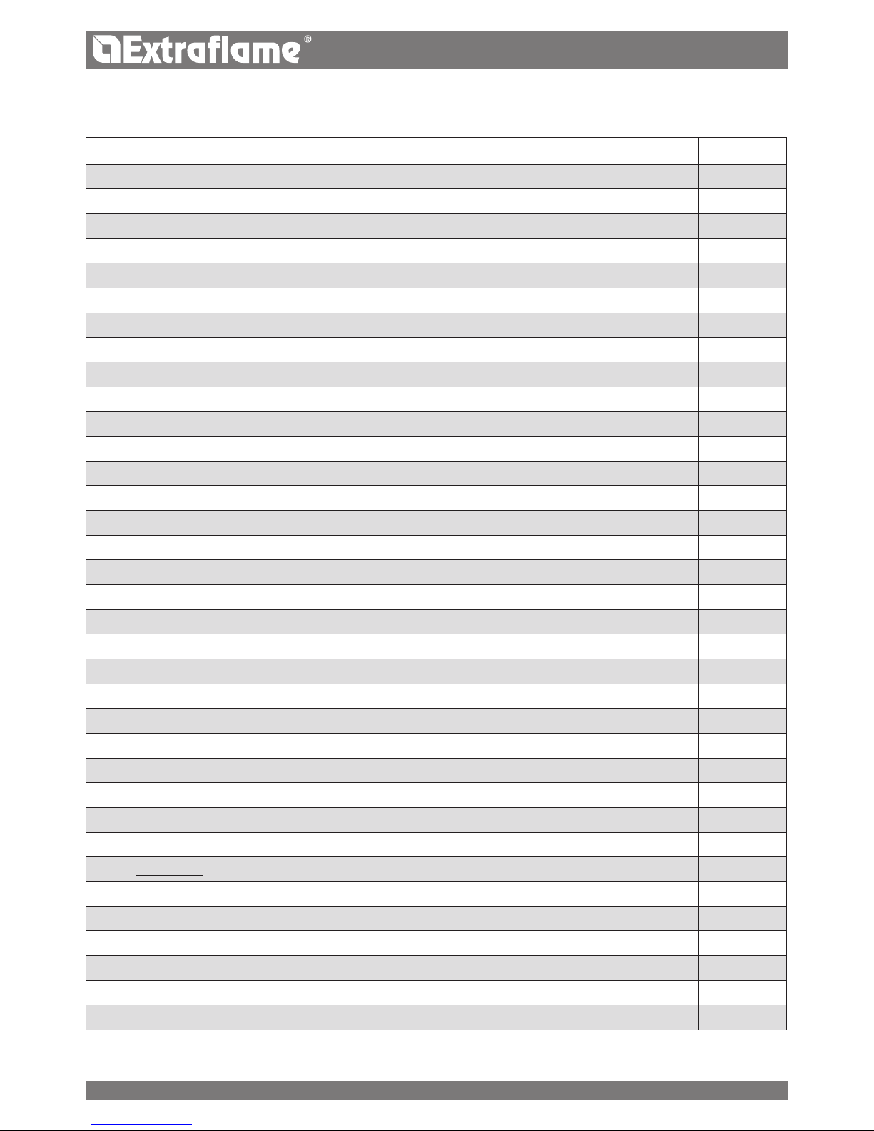
SPECIFICATIONS
FEATURES
Weight kg 256 260 335
Height mm 1304 1304 1408
Width mm 560 560 780
Depth mm 685 785 775
Exhaust tube diameter mm 120 120 120
Air intake tube diameter mm 50 50 60
Max global thermal power kW 16.9 25 33.9
Rated output thermal power (made with water) kW 15.2 22.5 31
Min global thermal power kW 5 7.4 9.5
Min thermal power output kW 4.4 6.6 8.6
Max hourly fuel consumption kg/h 3.5 5.2 7
Min hourly fuel consumption kg/h 1 1.5 2
Pellet tank capacity kg 43 60 71
Recommended chimney draught Pa 0.03-0.1 0.03-0.1 0.03-0.1
Rated electric power W 450 450 450
Electric power to Q
MIN
W 100 100 110
Electric power to Q
N
W 120 120 130
Stand By power W 3.5 4.0 4.0
Rated voltage Vac 230 230 230
Rated frequency Hz 50 50 50
Water inlet / outlet tube diameter " 1 1 1
Automatic exhaust tube diameter " 1/2 1/2 1/2
Pump head rating m 6 6 6
Maximum operating water pressure allowed bar 2.5 2.5 2.5
Min operating water pressure allowed bar 0.6 0.6 0.6
Flue gas temperature at reduced power °C 56.5 62.7 63
Flue gas temperature at rated power °C 103 136 122
Flue gas reduced power kg/s 0.0055 0.0065 0.0081
Flue gas rated power kg/s 0.0128 0.0164 0.0194
Class of the boiler 5 5 5
Combustion period h 12 12 10
Water supply control valve °C 65-80 65-80 65-80
Minimum return water temperature °C 55 55 55
Eciency at rated power % >90 >90 91.4
Noise
* dB 40 40 40
* Value measured in an anechoic chamber with a device operating at rated power.
4
A
B
C
D
D
F
E
F
E
G
G
H
H
I
I
J
J
HP30
HP 15 - 22
ENGLISH
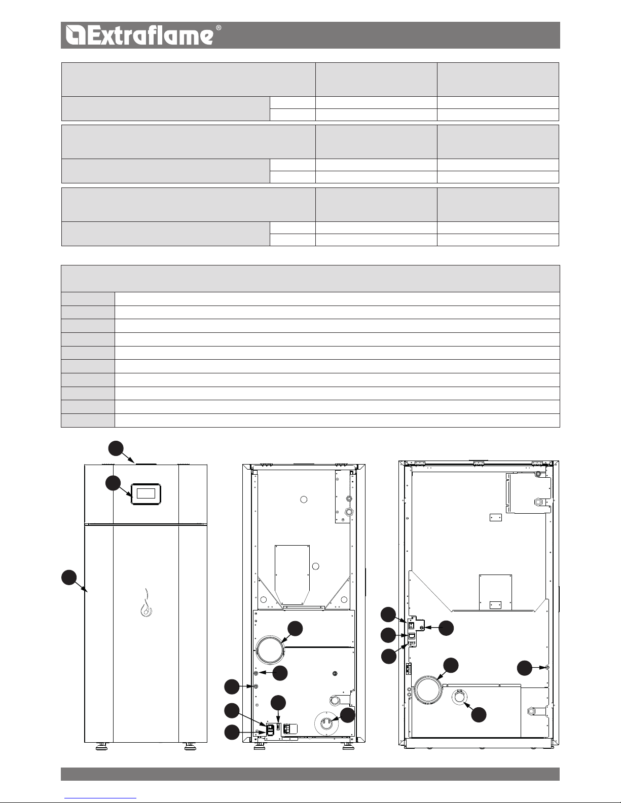
HP 15
WATER FLOW
(kg/h)
WATER SIDE
RESISTANCE
(Pa)
Temperature jump corresponding
ΔT = 10K 1312 160
ΔT = 20K 656 40
HP 22
WATER FLOW
(kg/h)
WATER SIDE
RESISTANCE
(Pa)
Temperature jump corresponding
ΔT = 10K 1938 367
ΔT = 20K 969 92
HP 30
WATER FLOW
(kg/h)
WATER SIDE
RESISTANCE
(Pa)
Temperature jump corresponding
ΔT = 10K 2668 687
ΔT = 20K 1334 172
IDENTIFICATION OF COMPONENTS
A Display
B Pellet tank cover
C Door
D Power socket for electric cable
E Safety thermostat (manual reset) 100°C
F Safety thermostat (manual reset) 85°C
G Combustion ue pipe
H Air intake tube for combustion
I Main power switch
J Serial port
5

ENGLISH
INTRODUCTION
The boilers produced in our factory are built with attention to the individual components so as to protect both the user and the
installer from any accidents. It is therefore recommended that after any intervention on the product, the authorised sta pay particular
attention to the electric connections, especially the stripped parts of the wires. These must not escape from the terminal board in any
situation, thus preventing possible contact with the live parts of the wire.
The instruction manual is an integral part of the product: make sure that it always accompanies the appliance, even if transferred to
other owners or user or is transferred to another place. If it is damaged or lost, request another copy from the area technician.
This generator must be intended for the use it has been specically made for. The manufacturer is exemptded from any liability,
contractual and extracontractual, for injury/damage caused to persons/animals and objects, due to installation, adjustment and
maintenance errors and improper use.
INSTALLATION
Installation of the generator and auxiliary equipment in relation to the heating system must comply with all current Standards and
Regulations and to those envisioned by the law. Installation must be carried out by authorised sta, who must provide the buyer with
a declaration of conformity for the system and will assume full responsibility for nal installation and as a consequence the correct
functioning of the installed product.
It is necessary to bear in mind all laws and national, regional, provincial and town council Standards present in the country the
appliance has been installed.
The Manufacturer cannot be held responsible for the failure to comply with such precautions. It is recommended to wash all the pipes
of the system well before installation to remove any residue that could compromise the correct operation of the appliance. During
installation, inform the user regarding:
a. If water leaks, he must close the water supply and promptly inform the after-sales technical service.
b. The system working pressure must be checked periodically. If the generator is not used for a long period of time, it is recommended
to contact the after-sales technical service to carry out at least the following operations:
- Set the master switch to position 0.
- Close the water taps of both the heating system and the domestic hot water system.
- Empty the heating system and the domestic hot water system if there is risk of freezing.
COMMISSIONING
After removing the packaging, ensure that the content is intact and complete.
Otherwise, contact the dealer where the appliance was purchased.
When commissioning the product, verify that all safety and control devices the generator consists of work properly. All electrical
components that make up the generator must be replaced with original spare parts exclusively by an authorised technical assistance
centre, thereby guaranteeing correct operation.
Before leaving the system, the sta in charge of commissioning must monitor the operation of the generator for at least one complete
work cycle. The geneerator must be serviced at least once a year, programming it in advance with the technical assistance centre
STANDARDS
The boilers have been designed and realised in compliance with the following Directives:
UNI EN 303-5 Boilers for central heating. Boilers for solid fuel, with manual and automatic feeding, with a nominal heat output
of up to 500 kW
DIRECTIVES
2004/108/EC: EMC directive
2006/95/EC: Low voltage directive
2006/42/EC: Machinery directive
2011/65/EU: RoHS 2” directive
FOR SAFETY
It is forbidden for the generator to be used by children or unassisted disabled persons.
Do not touch the generator when you are barefoot or when parts of the body are wet or humid.
The safety and adjustment devices must not be modied without the authorisation or indications of the manufacturer.
Do not pull, disconnect, twist electric cables leaving the gnerator, even if disconnected from the electric power supply mains.
Do not close or reduce the dimensions of the airing vents in the place of installation.
The airing vents are indispensable for correct combustion.
6
A
F
A
B
D
E
C
ENGLISH
Do not leave the packaging elements within reach of children or unassisted disabled persons.
The hearth door must always be closed during normal functioning of the product.
Avoid direct contact with parts of the appliance that tend to heat up during functioning.
Check for the presence of any obstructions before switching the appliance on following a prolonged standstill period.
The generator has been designed to function in any climatic condition. In particularly adverse conditions (strong wind, freezing)
safety systems may intervene to switch the generator o.
If this occurs, contact the technical after-sales service and always disable the safety system.
If the ue should catch re, be equipped with suitable systems for suocating the ames or request help from the re service.
If the generator should block, indicated by a signal on the display and that is not relative to lack of routine maintenance, contact
the technical after-sales centre.
THESE BOILERS MUST BE USED TO HEAT WATER TO A TEMPERATURE THAT DOES NOT EXCEED BOILING POINT
IN THE CONDITIONS OF INSTALLATION.
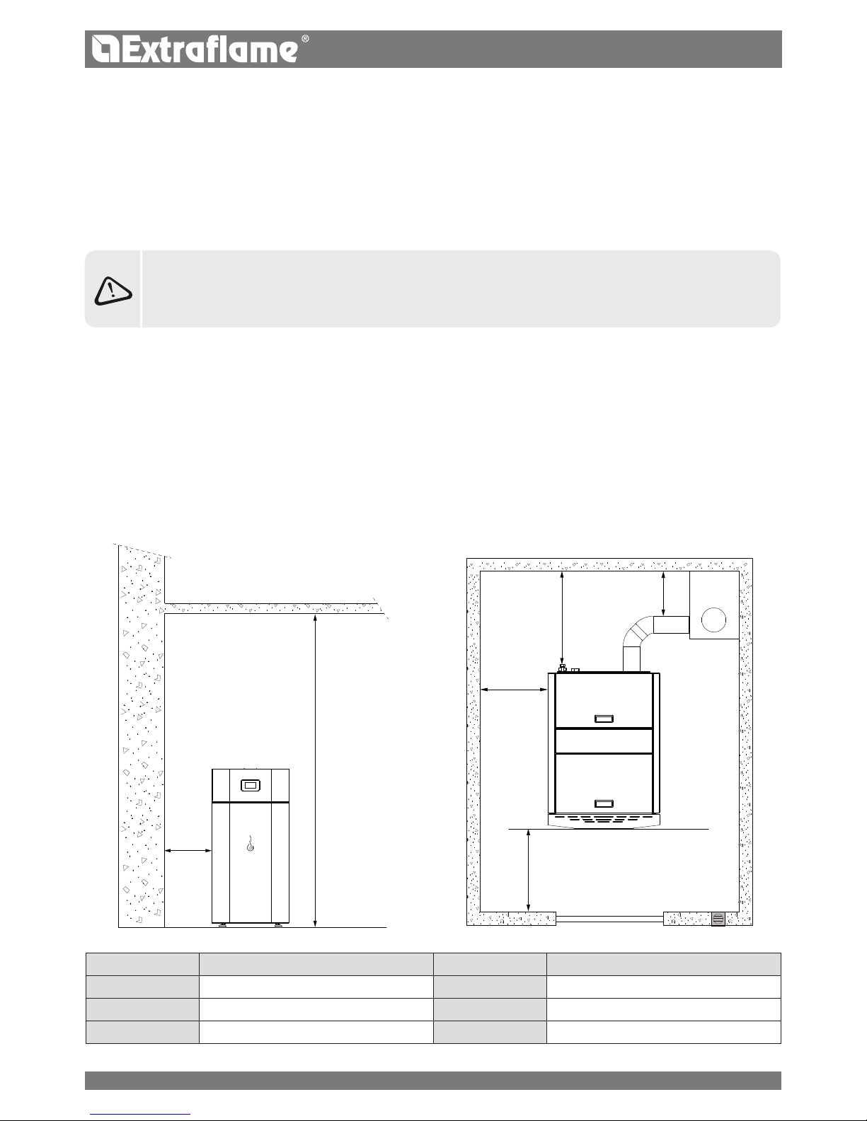
RECOMMENDED DISTANCES FOR THE BOILER COMPARTMENT
Below are a few images relative to the minimum distances required in the boiler room.
The company recommends the following measurements to be complied with:
REFERENCES NONINFLAMMABLE OBJECTS REFERENCES NONINFLAMMABLE OBJECTS
A 500 mm D 300 mm
B 1,000 mm E > 100 cm
2
C 1,000mm F 230cm
7

ENGLISH
WARNINGS
This instructions manual is an integral part of the product: make sure that it always accompanies the appliance, even if transferred to another
owner or user, or if transferred to another place. If it is damaged or lost, request another copy from the area technician. This product is
intended for the use for which it has been expressly designed. The manufacturer is exempt from any liability, contractual and extracontractual,
for injury/damage caused to persons/animals and objects, due to installation, adjustment and maintenance errors and improper use.
Installation must be performed by qualied sta, which assumes complete responsibility for the denitive installation and
consequent good functioning of the product installed. One must also bear in mind all laws and national, regional, provincial and
town council Standards present in the country in which the appliance has been installed, as well as the instructions contained in this
manual.
The Manufacturer cannot be held responsible for the failure to comply with such precautions.
After removing the packaging, ensure that the content is intact and complete. Otherwise, contact the dealer where the appliance was
purchased.
All electric components that make up the product must be replaced with original spare parts exclusively by an authorised after-sales centre,
thus guaranteeing correct functioning.
SAFETY
THE GENERATOR MUST NOT BE USED BY PERSONS INCLUDING CHILDREN WITH REDUCED PHYSICAL, SENSORY AND
MENTAL CAPACITIES OR WHO ARE UNSKILLED PERSONS, UNLESS THEY ARE SUPERVISED AND TRAINED REGARDING USE
OF THE APPLIANCE BY A PERSON RESPONSIBLE FOR THEIR SAFETY.
CHILDREN MUST BE CHECKED TO ENSURE THAT THEY DO NOT PLAY WITH THE APPLIANCE.
DO NOT TOUCH THE GENERATOR WHEN YOU ARE BAREFOOT OR WHEN PARTS OF THE BODY ARE WET OR DAMP.
THE SAFETY AND ADJUSTMENT DEVICES MUST NOT BE MODIFIED WITHOUT THE AUTHORISATION OR INDICATIONS
OF THE MANUFACTURER.
DO NOT PULL, DISCONNECT, TWIST ELECTRIC CABLES LEAVING THE STOVE, EVEN IF DISCONNECTED FROM THE
ELECTRIC POWER SUPPLY MAINS.
IT IS ADVISED TO POSITION THE POWER SUPPLY CABLE SO THAT IT DOES NOT COME INTO CONTACT WITH HOT PARTS
OF THE APPLIANCE.
THE POWER SUPPLY PLUG MUST BE ACCESSIBLE AFTER INSTALLATION.
DO NOT CLOSE OR REDUCE THE DIMENSIONS OF THE AIRING VENTS IN THE PLACE OF INSTALLATION. THE AIRING
VENTS ARE ESSENTIAL FOR CORRECT COMBUSTION.
DO NOT LEAVE THE PACKAGING ELEMENTS WITHIN REACH OF CHILDREN OR UNASSISTED DISABLED PERSONS.
THE HEARTH DOOR MUST ALWAYS BE CLOSED DURING NORMAL FUNCTIONING OF THE PRODUCT.
WHEN THE APPLIANCE IS FUNCTIONING AND HOT TO THE TOUCH, ESPECIALLY ALL EXTERNAL SURFACES, ATTENTION
MUST BE PAID
CHECK FOR THE PRESENCE OF ANY OBSTRUCTIONS BEFORE SWITCHING THE APPLIANCE ON FOLLOWING A
PROLONGED PERIOD OF INACTIVITY.
THE GENERATOR HAS BEEN DESIGNED TO FUNCTION IN ANY CLIMATIC CONDITION. IN PARTICULARLY ADVERSE
CONDITIONS STRONG WIND, FREEZING SAFETY SYSTEMS MAY INTERVENE THAT SWITCH THE GENERATOR OFF. IF THIS
OCCURS, CONTACT THE TECHNICAL AFTERSALES SERVICE AND ALWAYS DISABLE THE SAFETY SYSTEMS.
IN THE EVENT THE FLUE CATCHES FIRE, USE SUITABLE SYSTEMS FOR SUFFOCATING THE FLAMES OR REQUEST HELP
FROM THE FIRE BRIGADE.
THIS APPLIANCE MUST NOT BE USED TO BURN WASTE
DO NOT USE ANY FLAMMABLE LIQUIDS FOR IGNITION
DURING THE FILLING PHASE DO NOT PUT THE BAG OF PELLETS TO INTO CONTACT WITH THE PRODUCT
THE MAJOLICAS ARE TOP QUALITY ARTISAN PRODUCTS AND AS SUCH CAN HAVE MICRODOTS, CRACKLES AND
CHROMATIC IMPERFECTIONS. THESE FEATURES HIGHLIGHT THEIR VALUABLE NATURE. DUE TO THEIR DIFFERENT DILATION
COEFFICIENT, THEY PRODUCE CRACKLING, WHICH DEMONSTRATE THEIR EFFECTIVE AUTHENTICITY. TO CLEAN THE
MAJOLICAS, IT IS RECOMMENDED TO USE A SOFT, DRY CLOTH. IF A DETERGENT OR LIQUID IS USED, THE LATTER COULD
PENETRATE INSIDE THE CRACKLES, HIGHLIGHTING THEM.
ROUTINE MAINTENANCE
Based on Decree 22 January 2008 n°37 art.2, routine maintenance means interventions aimed at reducing degradation due to normal use,
as well as dealing with accidental events entailing the need of rst interventions, which however do not modify the structure of the system
upon which one is intervening or its intended use according to the requirements laid down by the technical standards in force and by the
manufacturer's use and maintenance manual.
We thank you for having chosen our company; our product is a great heating solution developed from the
most advanced technology with top quality machining and modern design, aimed at making you enjoy
the fantastic sensation that the heat of a ame gives, in complete safety.
8
ENGLISH
HYDRAULIC SYSTEM
Certain concepts referring to the Italian Standard UNI 10412-2 (2009) are described in this chapter.
As previously described, when installing, all national, regional, provincial and council Standards in force provided by the country in which the
appliance has been installed must be complied with.
During installation of the generator it is MANDATORY to adjust the system with a manometer in order to display the water pressure.
TABLE OF THE DEVICES FOR CLOSED VESSEL SYSTEMS PRESENT AND NOT PRESENT IN THE PRODUCT
Safety valve
p
Pump control thermostat (it is controlled by the water probe and the board program)
p
Acoustic alarm activation thermostat
Water temperature indicator (display)
p
Pressure transducer with view on the display
p
Acoustic alarm
Automatic adjustment circuit breaker switch (managed by board program)
p
Pressure transducer with minimum and maximum pressure switch alarm
p
Water overheating automatic circuit breaker switch (block thermostat)
p
Circulation system (pump)
p
Expansion system
p
INSTALLATION AND SAFETY DEVICES
The installation, relative system connections, commissioning and inspection of correct functioning must be carried out with the highest
professional standards, in full compliance with the national, regional and council Standards in force, as well as these instructions. For Italy,
installation must be carried out by professionally authorised sta (Ministerial Decree dated 22.01.08 n°37).
The Manufacturer declines all liability for damage/injury to objects/persons caused by the plant.
TYPE OF SYSTEM
There are 2 dierent types of system:
Open vessel system and closed vessel system.
The product has been designed and made to work with closed vessel systems.
CHECK THAT THE PRELOAD OF THE EXPANSION VESSEL IS SET TO 1.5 BAR.
SAFETY DEVICES FOR CLOSED VESSEL SYSTEM
According to Standard UNI 10412-2 (2009)in force in Italy, closed systems must be equipped with: safety valve, pump control thermostat,
acoustic alarm activation thermostat, temperature indicator, pressure indicator, acoustic alarm, regulation automatic circuit breaker switch,
automatic circuit breaker block switch (block thermostat), circulation system, expansion system, safety dissipation system incorporated with
the generator with thermal safety valve (self-activated), whenever the appliance does not have a temperature self-adjustment system.
DISTANCES OF SAFETY DEVICES ACCORDING TO THE STANDARD
The temperature safety sensors must be in place on the machine at a distance no greater than 30 cm from the ow connection. Whenever the
generators lack a device, those missing can be installed on the generator ow pipe, within a distance no greater than 1 m from the machine.
COMMISSIONING CHECKS
Before connecting the boiler:
a) wash all system piping thoroughly in order to remove any residues which might compromise the correct functioning of certain system
components (pumps, valves, etc.).
b) check to verify that the ue has adequate draught, that it is not narrowed and that other appliances do not discharge into the ue. This is to
prevent unexpected power increases. The ue tting can be mounted between the boiler and the ue only after this inspection. An inspection
of the connections with pre-existing ues is recommended.
ANTICONDENSATION DEVICE MANDATORY
Make sure a suitable anti-condensate circuit has been realised, which guarantees an appliance return temperature of at least 55°C. The
automatic thermostatic valve, for instance, is used in solid fuel boilers as it prevents cold water from returning into the exchanger. A high
return temperature allows eciency improvement, reduces formation of smoke condensation and prolongs the generator's life span. The
manufacturer recommends using the 55°C model with 1'' hydraulic connections.
Valve sold as an accessory (optional)
9
H
85°c
100°c
H
85°c
100°c
0
1
2
3
4
5
6
7
0 0,5 1 1,5 2 2,5 3 3,5
HP 30
HP15 - 22
ENGLISH
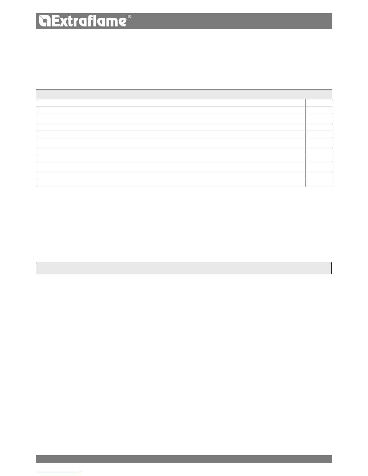
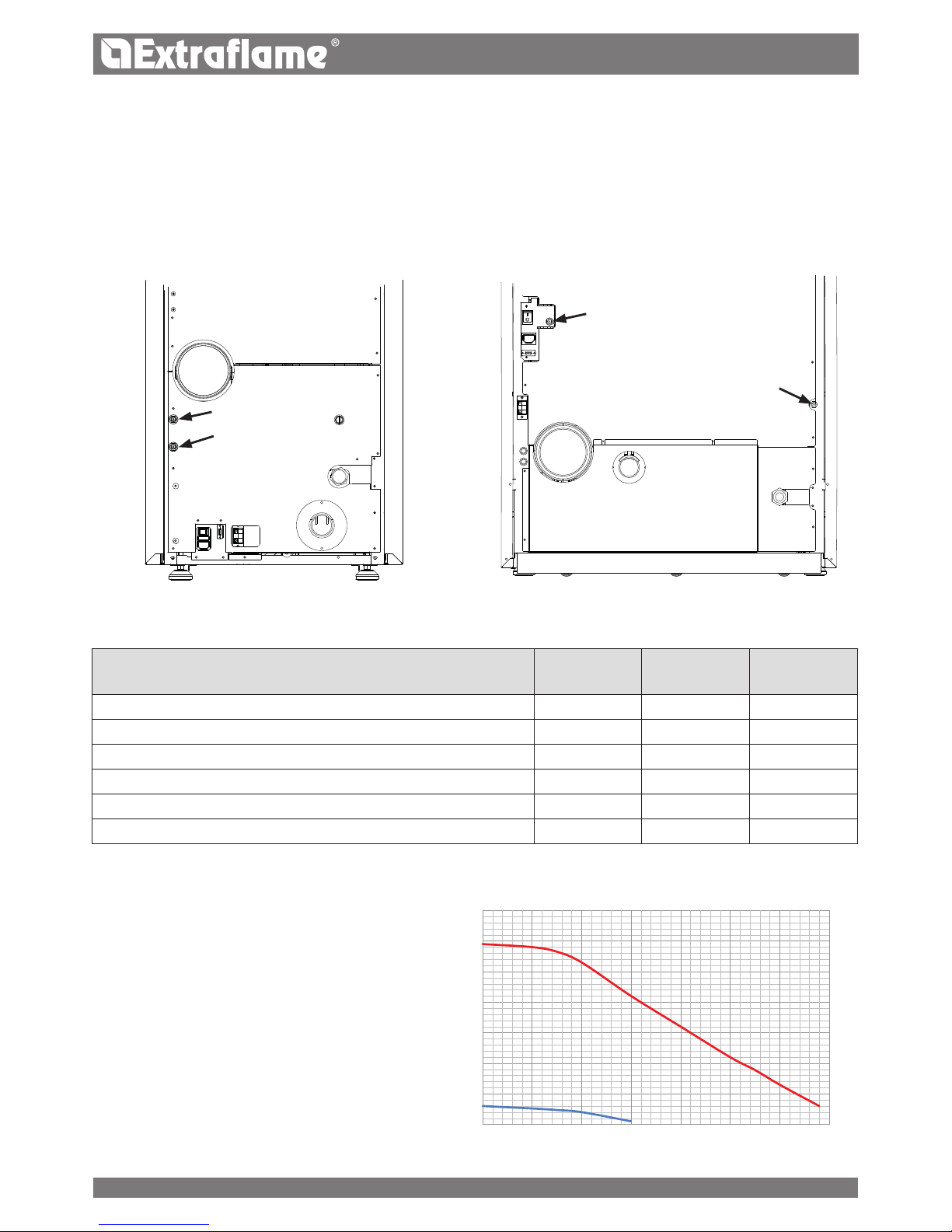
positioning
For correct product functioning, it is recommended to position it so that it is perfectly level, using a spirit level.
The diagram to the side illustrates the behaviour of the pump
used on our thermo-products at the speeds that can be set.
REARMs
The gures below illustrate the positions of the tank (85°C) and H2O (100°C) rearms. Contact the qualied technician if one of the rearms
should be triggered, so as to verify the cause.
FEAtUREs
Hp15 Hp22 Hp30
Water content of the thermo-product heat exchanger (l)
32
32 66
Volume of expansion vessel integrated in the thermo-product (l)
8
* 8* 12*
3 bar safety valve integrated in the thermo-product
P P P
Minimum and maximum pressure switch integrated into the thermo-
product
P P P
Pump integrated into the thermo-product
P P P
Pump max. head (m) 6 6 6
* Envision a possiblE additional Expansion vEssEl dEpEnding on thE systEm watEr contEnt.
Flow rate (m
3
/h)
Head (m)
10
 Loading...