

Extraflame FIANDRA IDRO User Manual

MADE IN ITALY
design & production
FIANDRA IDRO
004276688 - Rev 005
UK
THERMO PRODUCTS USER MANUAL

ENGLISH
2
ENGLISH
ENGLISH ............................................................................................................................................................................................................ 5
WarNINGS ........................................................................................................................................................................................................ 5
SafEty .............................................................................................................................................................................................................. 5
routINE MaINtENaNcE ................................................................................................................................................................................ 6
INStaLLatIoN .................................................................................................................................................................................................. 7
General ........................................................................................................................................................................................................................................................ 7
HErMEtIc INStaLLatIoN .............................................................................................................................................................................. 9
combustion air ......................................................................................................................................................................................................................................9
Fumes eXHaust sYstem....................................................................................................................................................................................................................... 9
HyDrauLIc SyStEM ...................................................................................................................................................................................... 10
installation and saFetY devices .............................................................................................................................................................................................10
aNtI-coNDENSatIoN DEVIcE (MaNDatory) .......................................................................................................................................... 11
fIaNDra IDro DEtaILS ................................................................................................................................................................................ 12
on/oFF .........................................................................................................................................................................................................................................................12
fEaturES........................................................................................................................................................................................................ 13
cHEckS aND MEaSurES for coMMISSIoNING ....................................................................................................................................... 13
tHe pellet load motor does not Function: ....................................................................................................................................................................13
bulb tHermostats - rearm ............................................................................................................................................................................................................13
StoVE poSItIoNING ..................................................................................................................................................................................... 14
NotE for corrEct opEratIoN ................................................................................................................................................................ 14
rearm...........................................................................................................................................................................................................................................................14
Fuse ...............................................................................................................................................................................................................................................................14
pELLEtS aND fEEDING ................................................................................................................................................................................. 15
pELLEt taNk - prESSurE cLoSurE. ........................................................................................................................................................... 15
raDIo/EMErGENcy carD ........................................................................................................................................................................... 16
LcD HaNDHELD rEMotE .............................................................................................................................................................................. 17
conFiGuration ......................................................................................................................................................................................................................................17
batterY tYpe and replacement .................................................................................................................................................................................................17
HaNDHELD fEaturES .................................................................................................................................................................................. 18
DISpLay .......................................................................................................................................................................................................... 19
GENEraL MENu ............................................................................................................................................................................................. 20
basic instructions ............................................................................................................................................................................................................................20
coMMISSIoNING SEttINGS ......................................................................................................................................................................... 21
date and time ........................................................................................................................................................................................................................................21
lanGuaGe ..................................................................................................................................................................................................................................................21
set deGrees ..............................................................................................................................................................................................................................................21
opEratIoN aND LoGIc ................................................................................................................................................................................ 22
SEt ................................................................................................................................................................................................................... 23
power ..........................................................................................................................................................................................................................................................23
room temperature .............................................................................................................................................................................................................................23
H2o temperature .................................................................................................................................................................................................................................23
ventilation ..............................................................................................................................................................................................................................................23
easY setup ................................................................................................................................................................................................................................................23
set cHrono ..............................................................................................................................................................................................................................................24
enable cHrono .....................................................................................................................................................................................................................................24
prG 1-4 .........................................................................................................................................................................................................................................................24
SEttINGS ........................................................................................................................................................................................................ 25
displaY ........................................................................................................................................................................................................................................................25
stand-bY ....................................................................................................................................................................................................................................................25
First load .................................................................................................................................................................................................................................................25
outlet air .................................................................................................................................................................................................................................................25
reset .............................................................................................................................................................................................................................................................25
aDDItIoNaL fuNctIoNS ............................................................................................................................................................................. 26
auX ................................................................................................................................................................................................................................................................26
lcd HandHeld remote room probe calibration ..........................................................................................................................................................26
additional tHermostat ..................................................................................................................................................................................................................26
additional tHermostat installation ...................................................................................................................................................................................26
cLEaNING aND MaINtENaNcE ...................................................................................................................................................................27
MaINtENaNcE ............................................................................................................................................................................................... 27
periodic cleaninG bY tHe user ...................................................................................................................................................................................................27
routINE MaINtENaNcE pErforMED by ENabLED tEcHNIcIaNS ...................................................................................................... 29
decommissioninG (end oF season) .........................................................................................................................................................................................29
DISpLayS ........................................................................................................................................................................................................ 31
aLarMS .......................................................................................................................................................................................................... 31
GuaraNtEE tErMS ...................................................................................................................................................................................... 33
attENtIoN
SurfacES caN bEcoME VEry Hot!
aLWayS uSE protEctIVE GLoVES!
During combustion, thermal energy is released that signicantly increases the heat of surfaces, doors, handles, controls, glass, exhaust
pipes, and even the front of the appliance. Avoid contact with those elements if not wearing protective clothing (protective gloves
included). Make sure children are aware of the danger and keep them away from the stove during operation.
3

ATTENZIONE TASSATIVO
PrImA dI mOVImENTArE lA STufA TOglIErE lE mAIOlIchE INdIcATE
PEr EVITArE dANNI.
ATTENTION - cOmPulSOrY
BEfOrE mOVINg ThE STOVE, kINdlY TAkE ThE cErAmIcS Off IN OrdEr TO
AVOId ANY dAmAgES
ATTENTION - OBlIgATOIrE
AVANT dE BOugEr lE POêlE , fAIrE ATTENTION à lEVEr lES cérAmIquES
INdIquéES POur éVITEr dES dégâTS
VOrSIchT - OBlIgATOrISch
BEVOr SIE dEN OfEN BEwEgEN , BITTE uNBEdINgT dIE BEZEIchNETE kErAmIk
kAchElN ENTfErNEN um SchädEN Zu VErmEIdEN
ATENcIÓN - PErENTOrIO
ANTES dE mOVEr lA ESTufA SAcAr lAS mAYÓlIcAS INdIcAdAS PArA EVITAr
dAñOS.
ENGLISH
4

ENGLISH
Warnings
This instructions manual is an integral part of the product: make sure that it always accompanies the
appliance, even if transferred to another owner or user, or if transferred to another place. If it is damaged
or lost, request another copy from the area technician. This product is intended for the use for which it has
been expressly designed. The manufacturer is exempt from any liability, contractual and extracontractual,
for injury/damage caused to persons/animals and objects, due to installation, adjustment and maintenance
errors and improper use.
Installation must be performed by qualied sta, which assumes complete responsibility for the
denitive installation and consequent good functioning of the product installed. One must also bear
in mind all laws and national, regional, provincial and town council Standards present in the country in
which the appliance has been installed, as well as the instructions contained in this manual.
The Manufacturer cannot be held responsible for the failure to comply with such precautions.
After removing the packaging, ensure that the content is intact and complete. Otherwise, contact the
dealer where the appliance was purchased.
All electric components that make up the product must be replaced with original spare parts exclusively
by an authorised after-sales centre, thus guaranteeing correct functioning.
safety
THE APPLIANCE MAY BE USED BY CHILDREN 8 YEARS OF AGE OR OLDER AND INDIVIDUALS
WITH REDUCED PHYSICAL, SENSORY, OR MENTAL CAPACITIES OR WITHOUT EXPERIENCE OR
THE NECESSARY KNOWLEDGE, PROVIDED THAT THEY ARE SUPERVISED OR HAVE RECEIVED
INSTRUCTIONS ON SAFE USE OF THE APPLIANCE AND THAT THEY UNDERSTAND THE INHERENT
DANGERS.
THE GENERATOR MUST NOT BE USED BY PERSONS (INCLUDING CHILDREN) WITH REDUCED
PHYSICAL, SENSORY AND MENTAL CAPACITIES OR WHO ARE UNSKILLED PERSONS, UNLESS THEY
ARE SUPERVISED AND TRAINED REGARDING USE OF THE APPLIANCE BY A PERSON RESPONSIBLE
FOR THEIR SAFETY.
THE CLEANING AND MAINTENANCE REQUIRED BY THE USER MUST NOT BE PERFORMED BY
CHILDREN WITHOUT SUPERVISION.
CHILDREN MUST BE CHECKED TO ENSURE THAT THEY DO NOT PLAY WITH THE APPLIANCE.
DO NOT TOUCH THE GENERATOR WHEN YOU ARE BAREFOOT OR WHEN PARTS OF THE BODY
ARE WET OR DAMP.
THE SAFETY AND ADjUSTMENT DEVICES MUST NOT BE MODIFIED WITHOUT THE AUTHORISATION
OR INDICATIONS OF THE MANUFACTURER.
DO NOT PULL, REMOVE, TWIST THE ELECTRICAL CABLES COMING OUT OF THE PRODUCT EVEN
IF IT IS DISCONNECTED FROM THE MAINS.
IT IS ADVISED TO POSITION THE POWER SUPPLY CABLE SO THAT IT DOES NOT COME INTO
CONTACT WITH HOT PARTS OF THE APPLIANCE.
THE POWER SUPPLY PLUG MUST BE ACCESSIBLE AFTER INSTALLATION.
DO NOT CLOSE OR REDUCE THE DIMENSIONS OF THE AIRING VENTS IN THE PLACE OF
INSTALLATION. THE AIRING VENTS ARE ESSENTIAL FOR CORRECT COMBUSTION.
We thank you for having chosen our company; our product is a great heating solution developed from the
most advanced technology with top quality machining and modern design, aimed at making you enjoy
the fantastic sensation that the heat of a ame gives, in complete safety.
5

ENGLISH
DO NOT LEAVE THE PACKAGING ELEMENTS WITHIN REACH OF CHILDREN OR UNASSISTED
DISABLED PERSONS.
THE HEARTH DOOR MUST ALWAYS BE CLOSED DURING NORMAL FUNCTIONING OF THE
PRODUCT.
WHEN THE APPLIANCE IS FUNCTIONING AND HOT TO THE TOUCH, ESPECIALLY ALL EXTERNAL
SURFACES, ATTENTION MUST BE PAID
CHECK FOR THE PRESENCE OF ANY OBSTRUCTIONS BEFORE SWITCHING THE APPLIANCE ON
FOLLOWING A PROLONGED PERIOD OF INACTIVITY.
THE GENERATOR HAS BEEN DESIGNED TO FUNCTION IN ANY CLIMATIC CONDITION. IN
PARTICULARLY ADVERSE CONDITIONS (STRONG WIND, FREEzING) SAFETY SYSTEMS MAY
INTERVENE THAT SWITCH THE GENERATOR OFF. IF THIS OCCURS, CONTACT THE TECHNICAL AFTERSALES SERVICE AND ALWAYS DISABLE THE SAFETY SYSTEMS.
IN THE EVENT THE FLUE CATCHES FIRE, USE SUITABLE SYSTEMS FOR SUFFOCATING THE FLAMES
OR REQUEST HELP FROM THE FIRE BRIGADE.
THIS APPLIANCE MUST NOT BE USED TO BURN WASTE
DO NOT USE ANY FLAMMABLE LIQUIDS FOR IGNITION
DURING THE FILLING PHASE DO NOT PUT THE BAG OF PELLETS TO INTO CONTACT WITH THE
PRODUCT
THE MAjOLICAS ARE TOP QUALITY ARTISAN PRODUCTS AND AS SUCH CAN HAVE MICRO-DOTS,
CRACKLES AND CHROMATIC IMPERFECTIONS. THESE FEATURES HIGHLIGHT THEIR VALUABLE
NATURE. DUE TO THEIR DIFFERENT DILATION COEFFICIENT, THEY PRODUCE CRACKLING, WHICH
DEMONSTRATE THEIR EFFECTIVE AUTHENTICITY. TO CLEAN THE MAjOLICAS, IT IS RECOMMENDED
TO USE A SOFT, DRY CLOTH. IF A DETERGENT OR LIQUID IS USED, THE LATTER COULD PENETRATE
INSIDE THE CRACKLES, HIGHLIGHTING THEM.
routine Maintenance
Based on Decree 22 January 2008 n°37 art.2, routine maintenance means interventions aimed at reducing
degradation due to normal use, as well as dealing with accidental events entailing the need of rst
interventions, which however do not modify the structure of the system upon which one is intervening or
its intended use according to the requirements laid down by the technical standards in force and by the
manufacturer's use and maintenance manual.
6
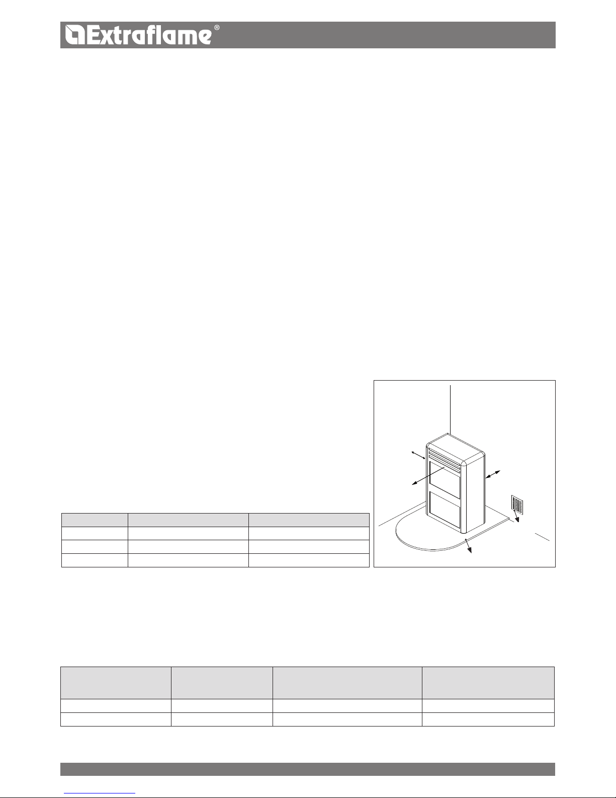
A
C
B
ENGLISH
Air inlet
REFERENCES INFLAMMABLE OBJECTS NONINFLAMMABLE OBJECTS
A 200 mm 100 mm
B 1500 mm 750 mm
C 200 mm 100 mm
oor protection
InstallIng Inserts
When installing inserts, access must be prevented to the internal parts of the appliance and it must not be possible to access live parts during
extraction operations.
Any wiring, for example the power cable or room probe, must be positioned so as not to be damaged during movement of the insert and
must not come into contact with hot parts.
VentIlatIon and aeratIon of the InstallatIon premIses
Ventilation is deemed sucient when the room is equipped with air inlets according to the table:
Appliance categories Reference standard
Percentage of the
net opening section with respect to the
appliance fumes outlet section
Minimum net opening value of the
ventilation duct
Pellet stoves UNI EN 14785 - 80 cm²
Boilers UNI EN 303-5 50% 100 cm²
In any case ventilation is deemed sucient when the pressure dierence between the external and internal environment is equal to or less
than 4 Pa.
InstallatIon
general
The ue gas exhaust and hydraulic connections must be carried out by qualied personnel who must issue installation conformity
documentation compliant with national standards.
The installer must provide the owner or person acting for him, according to the legislation in force, with the declaration of conformity,
supplied with:
1) the use and maintenance manual of the appliance and of the system components (such as for example, the smoke ducts, chimney, etc.);
2) photocopy or photograph of the chimney plaque;
3) system booklet (where applicable).
The installer must ask to be issued with a receipt stating that the documentation has been provided, and must keep it with a copy of the technical
documentation relating to the installation.
For installation in a condominium, prior approval from the condominium's administrator must be requested.
Where required, check the exhaust gas emissions after installation. Should a sampling point be installed, it must be airtight.
CompatIBIlItY
Installation in premises with re hazards is forbidden. Installation in residential premises (except for sealed operation appliances) is also forbidden:
in which there are liquid fuel-operated appliances with continuous or intermittent operation, which draw the combustion air in the
room in which they are installed, or
in which there are type B gas appliances intended for room heating, with or without production of domestic hot water and in adjacent
and adjoining premises, or
in which, in any case, the depression measured during installation between the internal and external environment is greater than 4 Pa
InstallatIons In Bathrooms, Bedrooms and studIo flats
Installation in bathrooms, bedrooms and studio ats is only allowed for sealed or closed hearth appliances with ducted combustion air taken
from the outside.
posItIonIng and safetY dIstanCes
The support surfaces and/or points must have a suitable capacity to bear the overall weight
of the appliance, accessories and coverings.
If the oor is made of a combustible material,
we recommending using a non-combustible material to protect the front part from any
burnt material which might fall during routine cleaning operations.
The generator must be level to function properly.
The adjacent, side and rear walls and the supporting surface must be made of noncombustible material. Installation adjacent to combustible or heat sensitive materials is
allowed as long as there is a suitable safety distance in between, which for pellet stoves is:
7
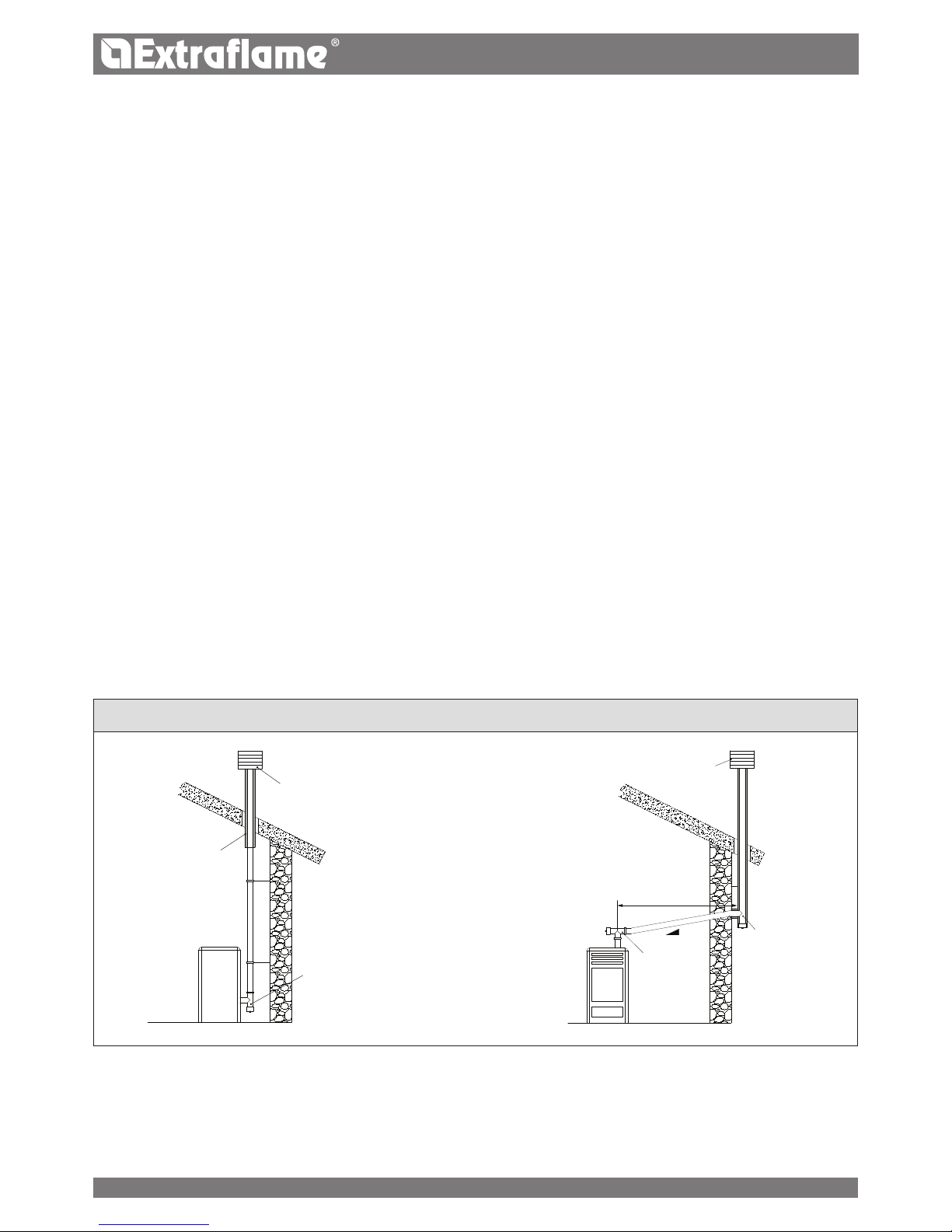
3 - 5%
Max 3 mt
ENGLISH
EXAMPLES OF CORRECT CONNECTION TO THE CHIMNEY
In the presence of type B gas appliances with intermittent operation not intended for heating, they must have their own aeration and/or
ventilation opening.
The air inlets must meet the following requirements:
they must be protected with grids, metal mesh, etc., but without reducing the net useful section;
they must be made so as to make the maintenance operations possible;
positioned so that they cannot be obstructed;
The clean and non-contaminated air ow can also be obtained from a room adjacent to that of installation (indirect aeration and
ventilation), as long as the ow takes place freely through permanent openings communicating with the outside.
The adjacent room cannot be used as a garage, or to store combustible material or for any other activity with a re hazard, bathroom,
bedroom or common room of the building.
flue gas eXhaust
The heat generator works in depression and is equipped with an outlet fan for ue gas extraction. There must be a single exhaust system for
the generator. Using a ue that is shared with other devices is not allowed.
The components of the ue gas exhaust system must be chosen in relation to the type of appliance to be installed in compliance with:
UNI/ TS 11278 in the event of metal chimneys, with particular attention to that stated in the specication;
UNI EN 13063-1 and UNI EN 13063-2, UNI EN 1457, UNI EN 1806 in the event of non-metallic chimneys.
The length of the horizontal section must be minimal and, in any case, no longer than 3 metres, with a minimum upward slope of 3%
There must not be more than 4 direction changes including the one due to the use of the "T" element.
A “T” tting with a condensation collection cap must be provided at the base of the vertical section.
If the exhaust is not inserted in an existing ue, a vertical section with a windproof end piece is required (UNI 10683).
The vertical duct can be inside or outside the building. If the smoke duct is inserted in an existing ue, it must be certied for solid fuel.
If the smoke duct is outside the building, it must always be insulated.
The smoke ducts must have at least one airtight inlet for ue gas sampling.
All the sections of the ue gas duct must be accessible to inspection.
Inspection openings must be provided for cleaning.
If the generator has a fume temperature lower than 160°C+ ambient temperature caused by the high yield (contact technicians) it
MUST be resistant to humidity.
ChImneY Cap
The chimney caps must meet the following requirements:
they must have a useful outlet section no less than double that of the chimney/ducted system on which it is installed;
they must be adapted in order to prevent the penetration of rain and snow in the chimney/ducted system;
they must be built so that, in the event of winds coming from all directions and from any angle, the expulsion of combustion products
is in any case ensured;
Protection from rain
and wind
Condensationproof "T" tting with
inspection plug
Insulated ue
Insulated "T"
tting with
inspection plug
Protection from rain and wind
"T" tting with
inspection
plug
ConneCtIon to the maIns eleCtrIC supplY
The generator is supplied with an electric power cable to be plugged into a 230V 50 Hz socket, possibly with a circuit breaker switch. The
socket must be easily accessible.
The electrical system must be compliant with standards. The eciency of the earthing circuit must be checked. Unsuitable earthing of the
system can cause malfunctioning for which the manufacturer will not be held liable.
Power supply variations beyond 10% can cause faulty operation of the product.
8
ENGLISH
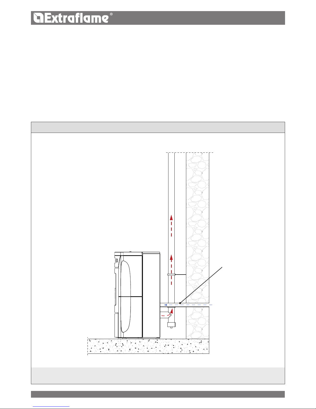
installation example
One must also bear in mind all laws and national, regional, provincial and town council regulations in force in the country in which the appliance has been
installed, as well as the instructions contained in this manual.
Max. 1.5 m - max.
2 elbows
Hermetic installation
Fiandra Idro is a completely sealed product with respect to the installation environment, which makes it ideal for passive houses, as it does
not take air from inside the homes.
combustion air
To respect the air-tight seal of the stove, the combustion air connection pipe must be directly connected to the outside using specic sealed
ttings and pipes.
Fumes exHaust sYstem
• If the generator has a fume temperature below 160°C+ (ambient temperature due to high eciency, see technical data), the fumes
exhaust system must be resistant to humidity.
• Should there be a possibility of the fumes condensating, provide an inspection "T" outside the stove.
9
ENGLISH
HYDRAULIC SYSTEM
Certain concepts referring to the Italian Standard UNI 10412-2 (2009) are described in this chapter.
As previously described, when installing, all national, regional, provincial and council Standards in force provided by the country in which the
appliance has been installed must be complied with.
During installation of the generator it is MANDATORY to adjust the system with a manometer in order to display the water pressure.
TABLE OF SAFETY DEVICES FOR CLOSED VESSEL SYSTEM AND NOT PRESENT IN THE PRODUCT
Safety valve
p
Pump control thermostat (it is managed by the water probe and the board program)
p
Water temperature indicator (display)
p
Pressure transducer with display
p
Automatic circuit breaker adjustment switch (managed by board program)
p
Pressure transducer with minimum and maximum pressure switch alarm
p
Water overheating automatic circuit breaker switch (block thermostat)
p
Circulation system (pump)
p
Expansion system
p
INSTALLATION AND SAFETY DEVICES
The installation, relative system connections, commissioning and inspection of correct functioning must be carried out perfectly, in full
compliance with Standards in force, national, regional and municipal, as well as these instructions. For Italy, installation must be carried out by
professionally qualied sta (Ministerial Decree dated 22.01.08 n°37).
Extraame S.p.A. declines all responsibility for damage to objects and/or persons caused by the system.
TYPE OF SYSTEM
There are 2 dierent types of system:
Open vessel system and closed vessel system.
The product has been designed and made to work with closed vessel systems.
CHECK THAT THE PRELOAD OF THE EXPANSION VESSEL IS SET TO 1.5 BAR.
SAFETY DEVICES FOR CLOSED VESSEL SYSTEM
In accordance with the UNI 10412-2 (2009) regulation in force in Italy, all the closed systems must be tted with: safety valve, pump control
thermostat, temperature indicator, pressure indicator, automatic circuit breaker block switch (block thermostat), circulation system,
expansion system, and safety dissipation built-in to the generator with thermal safety valve (self-activated), if the appliance does not have a
temperature self-adjustment system.
Pay attention to the correct sizing of the system:
generator power compared to the thermal requirement
possible need for a buer tank
10

ENGLISH
DISTANCES OF SAFETY DEVICES ACCORDING TO THE STANDARD
The temperature safety sensors must be in place on the machine at a distance no greater than 30 cm from the ow connection. Whenever the
generators lack a device, those missing can be installed on the generator ow pipe, within a distance no greater than 1 m from the machine.
COMMISSIONING CHECKS
Before connecting the boiler:
a) wash all system piping thoroughly in order to remove any residues which might compromise the correct functioning of certain system
components (pumps, valves, etc.).
b) The company highly recommends installing a magnetic lter in the generator return to increase the life of the boiler, facilitate removal of
impurities, and increase the overall eciency of the system.
c) check to verify that the ue has adequate draught, that it is not narrowed and that other appliances do not discharge into the ue. This is to
prevent unexpected power increases. The ue tting can be mounted between the boiler and the ue only after this inspection. An inspection
of the connections with pre-existing ues is recommended.
ANTICONDENSATION DEVICE MANDATORY
Make sure a suitable anti-condensate circuit has been realised, which guarantees an appliance return temperature of at least 55°C. The
automatic thermostatic valve, for instance, is used in solid fuel boilers as it prevents cold water from returning into the exchanger. A high
return temperature allows eciency improvement, reduces formation of smoke condensation and prolongs the generator’s life span. The
manufacturer recommends using the 55°C model with 1” hydraulic connections.
For the products with the PWM pump control thermostat, installation is considered equivalent to the realisation of a suitable anti-condensate
circuit in the case where::
- the heat generator pump is the only one in the installation, or
- there is a plate heat exchanger between the heat generator and the installation, or
- there is a hydraulic compensator or an inertial storage tank (buer) between the heat generator and the installation
Valve on sale as an accessory (optional)
11
 Loading...