

Extraflame Pellet stove, GRAZIOSA PLUS, IRMA PLUS, SOUVENIR, ILENIA User Manual
...
LED
pellet stoves UseR MANUAl
eNGlIsH/INGlese

ENGLISH
2

index
ENGLISH
We thank you for having chosen our company; our product is a great heating solution developed from the
most advanced technology with top quality machining and modern design, aimed at making you enjoy
the fantastic sensation that the heat of a ame gives, in complete safety.
enGLiSH .....................................................................................................................................................................................................................................4
WarninGS ........................................................................................................................................................................................................ 4
Safety .............................................................................................................................................................................................................. 4
routine Maintenance ................................................................................................................................................................................ 4
deviceS ............................................................................................................................................................................................................ 5
reference StandardS ................................................................................................................................................................................ 5
General ........................................................................................................................................................................................................................................................ 6
inStaLLation ..................................................................................................................................................................................................7
Inserts InstallatIon ........................................................................................................................................................................................................................... 7
fuMeS exHauSt SySteM............................................................................................................................................................................... 8
General requIrements ...................................................................................................................................................................................................................... 8
smoke duct ............................................................................................................................................................................................................................................... 9
chImney ......................................................................................................................................................................................................................................................11
chImney caps .........................................................................................................................................................................................................................................11
Fumes eXhaust system product requIrements .............................................................................................................................................................12
combustIon products outlet quota ..................................................................................................................................................................................12
technIcal InstallatIon documentatIon ...........................................................................................................................................................................13
Souvenir and iLenia SpacerS ................................................................................................................................................................. 14
Hot air ductinG ..........................................................................................................................................................................................14
elIsIr .............................................................................................................................................................................................................................................................14
souVenIr - IlenIa ..................................................................................................................................................................................................................................15
GraZIosa plus & Irma plus ...........................................................................................................................................................................................................16
emma plus & tosca plus ..................................................................................................................................................................................................................16
addItIonal thermostat For ductInG motor control .............................................................................................................................................17
rearMS ........................................................................................................................................................................................................... 17
inStaLLinG coMfort Maxi/ coMfort pLuS .......................................................................................................................................... 18
assembly wIth slIdInG base ..........................................................................................................................................................................................................18
comFort plus.........................................................................................................................................................................................................................................19
pedeStaL aSSeMbLy (optionaL): ............................................................................................................................................................. 19
front peLLet feedinG kit (optionaL) ...................................................................................................................................................20
air circuLation pipeS ................................................................................................................................................................................ 20
Insert eXtractIon ...............................................................................................................................................................................................................................22
mountInG the Frames ......................................................................................................................................................................................................................23
peLLetS and feedinG ................................................................................................................................................................................. 23
controL paneL ............................................................................................................................................................................................ 24
dIsplay Icons key .................................................................................................................................................................................................................................24
General menu ........................................................................................................................................................................................................................................25
basIc InstructIons ............................................................................................................................................................................................................................25
reMote controL ......................................................................................................................................................................................... 26
type and replacement oF batterIes .......................................................................................................................................................................................26
coMMiSSioninG SettinGS ......................................................................................................................................................................... 26
maIns Frequency 50/ 60hZ .............................................................................................................................................................................................................26
adjustInG tIme, day, month and year ...................................................................................................................................................................................27
adjustInG lanGuaGe.........................................................................................................................................................................................................................27
operation and LoGic ................................................................................................................................................................................ 28
additionaL tHerMoStat (optionaL) .................................................................................................................................................... 29
uSer Menu..................................................................................................................................................................................................... 29
dIsplay ........................................................................................................................................................................................................................................................29
pellet Feed adjustment .................................................................................................................................................................................................................29
V1- aIr...........................................................................................................................................................................................................................................................30
stand by .....................................................................................................................................................................................................................................................30
keys locked .............................................................................................................................................................................................................................................31
V2 - aIr..........................................................................................................................................................................................................................................................32
reset .............................................................................................................................................................................................................................................................32
enabLe cHrono ........................................................................................................................................................................................... 32
cHrono .......................................................................................................................................................................................................... 32
proGrammInG eXample ...................................................................................................................................................................................................................33
cLeaninG and Maintenance ...................................................................................................................................................................34
cleanInG and maIntenance by the user .............................................................................................................................................................................34
routine Maintenance ............................................................................................................................................................................. 39
diSpLayS ........................................................................................................................................................................................................42
aLarMS .......................................................................................................................................................................................................... 43
3

ENGLISH
WARNINGS
This instructions manual is an integral part of the product: make sure that it always accompanies the appliance, even if
transferred to another owner or user, or if transferred to another place. If it is damaged or lost, request another copy from the
area technician. This product is intended for the use for which it has been expressly designed. The manufacturer is exempt from
any liability, contractual and extracontractual, for injury/damage caused to persons/animals and objects, due to installation,
adjustment and maintenance errors and improper use.
Installation must be performed by qualied sta, which assumes complete responsibility for the denitive installation
and consequent good functioning of the product installed. One must also bear in mind all laws and national, regional,
provincial and town council Standards present in the country in which the appliance has been installed, as well as the
instructions contained in this manual.
The Manufacturer cannot be held responsible for the failure to comply with such precautions.
After removing the packaging, ensure that the content is intact and complete. Otherwise, contact the dealer where the appliance
was purchased.
All electric components that make up the product must be replaced with original spare parts exclusively by an authorised aftersales centre, thus guaranteeing correct functioning.
SAFETY
The generator must not be used by persons (including children) with reduced physical, sensory and mental capacities or
who are unskilled persons, unless they are supervised and trained regarding use of the appliance by a person responsible for
their safety.
Children must be checked to ensure that they do not play with the appliance.
Do not touch the generator when you are barefoot or when parts of the body are wet or damp.
The safety and adjustment devices must not be modied without the authorisation or indications of the manufacturer.
Do not pull, disconnect, twist electric cables leaving the stove, even if disconnected from the electric power supply mains.
It is advised to position the power supply cable so that it does not come into contact with hot parts of the appliance.
The power supply plug must be accessible after installation.
Do not close or reduce the dimensions of the airing vents in the place of installation. The airing vents are essential for
correct combustion.
Do not leave the packaging elements within reach of children or unassisted disabled persons.
The hearth door must always be closed during normal functioning of the product.
When the appliance is functioning and hot to the touch, especially all external surfaces, attention must be paid
Check for the presence of any obstructions before switching the appliance on following a prolonged period of inactivity.
The generator has been designed to function in any climatic condition (even critical). In particularly adverse conditions
(strong wind, freezing) safety systems may intervene that switch the generator o. If this occurs, contact the technical aftersales service and always disable the safety systems.
In the event the ue catches re, use suitable systems for suocating the ames or request help from the re brigade.
This appliance must not be used to burn waste
Do not use any ammable liquids for ignition
During the lling phase do not put the bag of pellets to into contact with the product
The majolicas are top quality artisan products and as such can have micro-dots, crackles and chromatic imperfections.
These features highlight their valuable nature. Due to their dierent dilation coecient, they produce crackling, which
demonstrate their eective authenticity. To clean the majolicas, it is recommended to use a soft, dry cloth. If a detergent or
liquid is used, the latter could penetrate inside the crackles, highlighting them.
ROUTINE MAINTENANCE
Based on Decree 22 January 2008 n°37 art.2, routine maintenance means interventions aimed at reducing degradation due to
normal use, as well as dealing with accidental events entailing the need of rst interventions, which however do not modify
the structure of the system upon which one is intervening or its intended use according to the requirements laid down by the
technical standards in force and by the manufacturer's use and maintenance manual.
4
ENGLISH
DEVICES
(in the relevant models)
Door micro switch: With the door open, the operation of the
burn pot cleaning system is blocked
Electronic pressure switch: in the event of inadequate pression,
it sends the machine in alarm conditions
F 2.5 A 250 V fuse (stoves): protects the machine from violent
current surges
85°C calibrated mechanical bulb with manual rearm:
intervenes by blocking fuel feed if the pellet tank t° reaches the
limit of 85°C. Rearm must be performed by qualied sta and/
or the manufacturer's technical after-sales assistance.
Pellet tank temperature control probe: if the tank over-heats,
the machine automatically modulates to return to normal
temperature values
Mechanical air pressure switch: blocks the pellet in the event of
insucient depression
REFERENCE STANDARDS
The installation must be in compliance with:
UNI 10683 (2012) heat generators fed with wood and
other solid fuels: installation.
The chimneys must be in compliance with:
UNI EN 13063-1 and UNI EN 13063-2, UNI EN 1457, UNI
EN 1806 in the event of non-metallic chimneys:
EN 13384-1 (13384) chimneys. Thermal and uid dynamic
calculation methods.
UNI EN 1443 (2005) chimneys: general requirements.
UNI EN 1457 (2012) chimneys: clay/ceramic ue liners.
UNI/TS 11278 (2008) Metal - chimneys/ue liners/ue
ducts.
UNI 7129 point 4.3.3 Fire Brigade provisions, local rules
and regulations.
NATIONAL, REGIONAL, PROVINCIAL AND TOWN
COUNCIL REGULATIONS
One must also bear in mind all laws and national, regional,
provincial and town council Standards present in the country
in which the appliance has been installed.
TERMS AND DEFINITIONS
Aeration: Air renewal is required both for the disposal of
the combustion products, and to prevent mixtures with a
hazardous content of non-combusted gases.
Closed hearth appliance: Appliance designed for operation
with closed combustion chamber.
Forced draught appliance: Appliance with ventilation in the
fumes circuit and combustion with fumes ow at a positive
pressure with respect to the environment.
Chimney: Structure consisting in one or several walls
containing one or several outow airways.
The purpose of this predominantly vertical element is to expel
the combustion products at a convenient height from the
ground.
Smoke duct: Component or components that connect the
outlet of the heat generator to the chimney.
Chimney cap: Device that placed on the chimney outlet
allows the dispersion of the combustion products even in
presence of adverse weather conditions.
Condensation: Liquid products which form when the fumes
temperature is lower or equal to the water dew point.
Ducting pipe: Pipe made up of one or several predominantly
vertical elements, specically suitable for collecting and
expelling the fumes, as well as to withstand the relative
components and any condensate over time,
suitable to be installed in a chimney, existing or new technical
compartment, even in new buildings.
Sealed installation: Installation of an appliance with sealed
operation, so that all the air required for combustion is taken
from outside.
Maintenance: Set of procedures required to ensure and
maintain safety and functionality over time and maintain the
eciency of the system within the prescribed parameters.
Chimney system: Chimney installed using a combination
of compatible components, manufactured or specied by a
sole manufacturer whose product liability covers the entire
chimney.
Fumes exhaust system: Flue gas exhaust system,
independent from the appliance made up of a smoke duct,
chimney or individual ue and chimney cap.
Radiation area: Area immediately in front of the hearth in
which the radiant heat caused by combustion is diused.
Reux area: Area beyond the extrados of the roof in which
overpressure or depressions occur, which may aect the
proper discharge of the combustion products.
5

ENGLISH
FUNCTIONAL OPERATIONS DIAGRAM
State of the art installation and proper system operation include a series of activities:
1. Preliminary activities:
Verication of the suitability of the power of the heat generator based on the characteristics of the system
verication of the suitability of the installation site,
verication of the suitability of the fumes exhaust system,
verication of the suitability of the outside air inlets;
2. Installation:
implementation of ventilation and connection to the outer air inlets,
implementation and connection to the fumes exhaust system,
assembly and installation,
electric and hydraulic connections,
installation of insulation,
ignition and operation test,
installation of nishings and coverings;
3. Issue of complementary documentation;
4. Inspection and maintenance.
Other actions may be required in relation to specic requests of the competent authority.
PRELIMINARY ACTIVITIES
GENERAL
Verication of compatibility of the system, of any restrictions required by local administrative regulations, special or conventional
requirements resulting from condominium regulations, constraints, laws or administration deeds must precede any other
assembly or installation operation.
One must especially verify the suitability:
of the installation premises, of the appliances already installed in the installation premises and in the adjacent and
adjoining premises, also powered by dierent fuels, with particular reference to non-compliant installations.
of the fumes exhaust system
of the outside air inlets
SUITABILITY OF THE FUMES EXHAUST SYSTEM
Installation must be preceded by a compatibility test between the appliance and the fumes exhaust system, by verifying:
the existence of documentation relating to the system;
existence and content of the chimney plaque;
suitability of the internal section of the chimney;
absence of obstructions all along the chimney;
predominantly vertical height and development of the chimney;
existence and suitability of the chimney cap;
distance of the outside wall of the chimney and of the smoke duct from
combustible materials;
chimney type and material;
absence of other chimney connections.
6
B
C
A
S
ENGLISH
INSTALLATION
Installation in premises with re hazards is forbidden. Installation in residential premises (except for sealed operation appliances)
is also forbidden:
in which there are liquid fuel-operated appliances with continuous or intermittent operation, which draw the combustion
air in the room in which they are installed, or
in which there are type B gas appliances intended for room heating, with or without production of domestic hot water and
in adjacent and adjoining premises, or
in which, in any case, the depression measured during installation between the internal and external environment is
greater than 4 Pa
Installations in bathrooms, bedrooms and studio ats
Installation in bathrooms, bedrooms and studio ats is only allowed for sealed or closed hearth appliances with ducted
combustion air taken from the outside.
Installation premises requirements
The support surfaces and/or points must have a suitable load-bearing capacity to support the weight of the appliance, of the
accessories and coatings.
The adjacent, side and rear walls and the supporting surface must be made of non-combustible material. Installation near combustible
materials or those sensitive to heat is permitted as long as there is a suitable safety distance, which for pellet stoves is equal to:
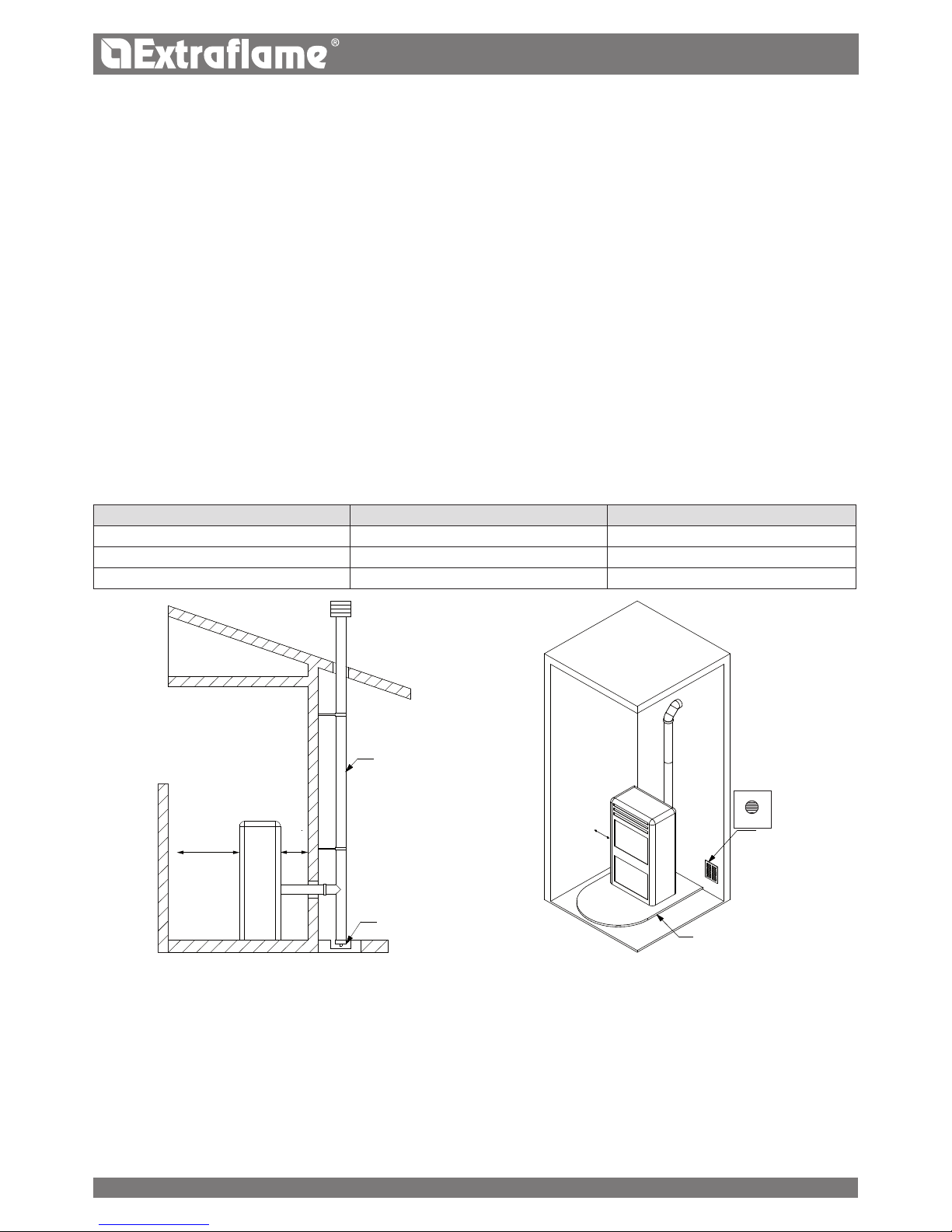
REFERENCES INFLAMMABLE OBJECTS NONINFLAMMABLE OBJECTS
A 200 mm 100 mm
B 1500 mm 750 mm
C 200 mm 100 mm
In any case the temperature of the adjacent combustible materials must not reach a temperature equal to or greater than the
room temperature increased by 65°C.
The minimum volume of the premises in which to install the appliance must be greater than 15 m³.
INSERTS INSTALLATION
In the event of installation of inserts, access to the internal parts of the device is to be prevented and, during extraction, it should
not be possible to access to live parts.
Any wiring, such as a power supply cable or room sensors must be positioned so as not to be damaged during movement of the
insert, or come into contact with hot parts.
Air inlet
S= oor protection
Flue
Inspection
gure 1 gure 2
7

ENGLISH
VENTILATION AND AERATION OF THE INSTALLATION PREMISES
Ventilation is deemed sucient when the room is equipped with air inlets according to the table:
Air inlet
See gure 2
Appliance categories Reference standard
Percentage of the
net opening section with
respect to the appliance fumes
outlet section
Minimum net opening value of
the ventilation duct
Pellet stoves UNI EN 14785 - 80 cm²
Boilers UNI EN 303-5 50% 100 cm²
In any case ventilation is deemed sucient when the pressure dierence between the external and internal environment is
equal to or less than 4 Pa.
In the presence of type B gas appliances with intermittent operation not intended for heating, they must have their own aeration
and/or ventilation opening. The air inlets must meet the following requirements:
they must be protected with grids, metal mesh, etc., but without reducing the net useful section;
they must be made so as to make the maintenance operations possible;
positioned so that they cannot be obstructed;
The ow of clean, uncontaminated air can also be obtained from a room adjacent to that of installation (indirect aeration and
ventilation), as long as the ow takes place freely through permanent openings communicating with the outside.
The adjacent room cannot be used as a garage, warehouse of combustible material or for any other activity with a re hazard,
bathroom, bedroom or common room of the building.
FUMES EXHAUST SYSTEM
GENERAL REQUIREMENTS
The heat generator works in a vacuum and has an output fan for fume extraction. Each appliance must be connected to a suitable
fumes exhaust system and ensure adequate dispersion of the combustion products into the atmosphere. The combustion products
must discharged above the roof. Direct discharge from the wall or towards closed spaces is forbidden, even with clear skies.
In particular, it is forbidden to use exible and extendible metal pipes.
The chimney should only receive the exhaust of the smoke duct connected to the appliance; collective ues or conveying
exhausts from hoods above cooking appliances of any kind, or exhausts from other generators into the chimney itself or smoke
duct are not allowed.
The smoke duct and the chimney must be connected with a continuity solution, in order to prevent the chimney from resting
on the appliance.
It is forbidden to have other air supply channels and pipes for plant engineering transit inside the fumes exhaust systems,
especially if over-sized.
The components of the fumes exhaust system must be chosen in relation to the type
of appliance to be installed in compliance with:
in the event of metal chimneys, UNI/ TS 11278, with particular attention to what is stated in the specication;
in the event of non-metallic chimneys: UNI EN 13063-1 and UNI EN 13063-2, UNI EN 1457, .-UNI EN 1806; considering especially:
temperature class;
pressure class (fumes seal) at least equal to the seal required for the appliance;
moisture resistance (resistance to condensation);
class or level of corrosion and specication of the materials constituting the inner wall in contact with the fumes.
soot re resistance class;
minimum distance from combustible materials
Where due to high eciency a pellet stove has fumes at a temperature of less than 160°C + ambient (see technical data)
it must be resistant to moisture.
The installer of the fumes exhaust system, once the installation is complete and the relevant checks and inspections have been
made, must x the chimney plaque supplied by the manufacturer with the product in a visible manner, near the replace, and
which must be completed with the following information:
8
a
a
b.1
b
a
a
a
a
b.1
b.1
b b
OK
OK
ENGLISH
SMOKE DUCT
General requirements
The smoke ducts must be installed in compliance with the following general requirements:
be equipped with at least one sealed outlet for eventual fumes sampling;
they must be insulated if they cross through rooms that are not to be heated or outside the building;
they must not cross rooms in which the installation of combustion appliances is forbidden, nor in other premises
compartmentalised against re or with a re hazard, nor in rooms and/or areas that cannot be inspected;
they must be installed so as to allow normal thermal expansion;
they must be tted to the opening of the chimney without protruding inwards;
the use of exible metal pipes to connect the appliance to the chimney is not allowed;
nominal diameter;
distance from combustible materials, indicated in millimetres, followed by the arrow and ame symbol;
installer data and date of installation.
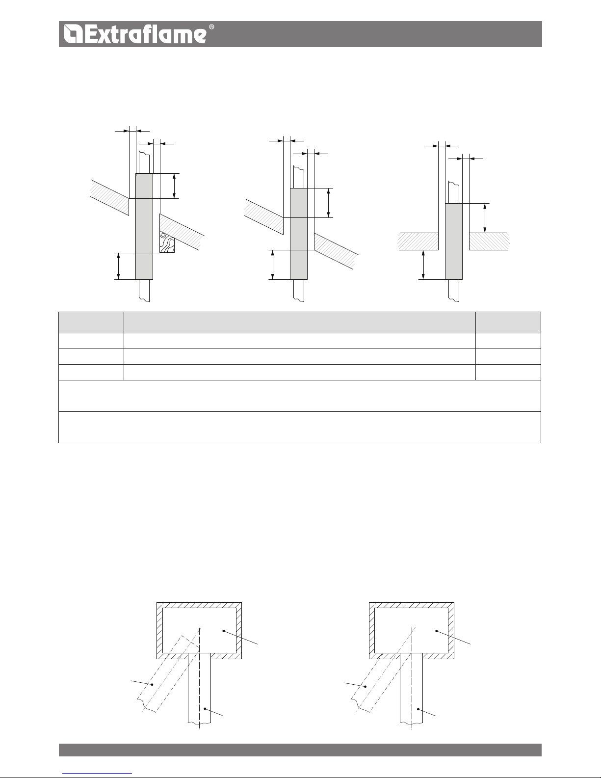
Every time one must cross combustible materials, the following indications must be complied with:
SYMBOL DESCRIPTION QUOTAMM
b Minimum distance of combustible materials from the intrados of the framework/oor/wall 500
b.1 Minimum distance of combustible materials from the extrados of the framework/oor 500
a Minimum distance from combustible materials dened by the manufacturer G(xxx)
The single wall pipes are indicated in white.
The insulated double wall chimney systems are indicated in grey.
One can disregard the quota only in the event of using an appropriate heat protection screen (for example: wall plate) to
protect the intrados of the framework/oor
Chimney
Chimney
Incorrect
Correct
9
ENGLISH
counter-slope sections are not allowed;
the smoke ducts must have, along their entire length, a diameter that is no less than that of the attachment of the appliance
exhaust pipe; any section changes are allowed only on the inlet to the chimney;
they must be installed so as to limit the formation of condensation and prevent their release from the joints;
they must be positioned at a distance no less than that indicated in the product specications from combustible materials;
the smoke channel/duct must allow to collect the soot and to be cleaned using a swab and inspected after being
disassembled, or through inspection openings when not accessible from inside the appliance.
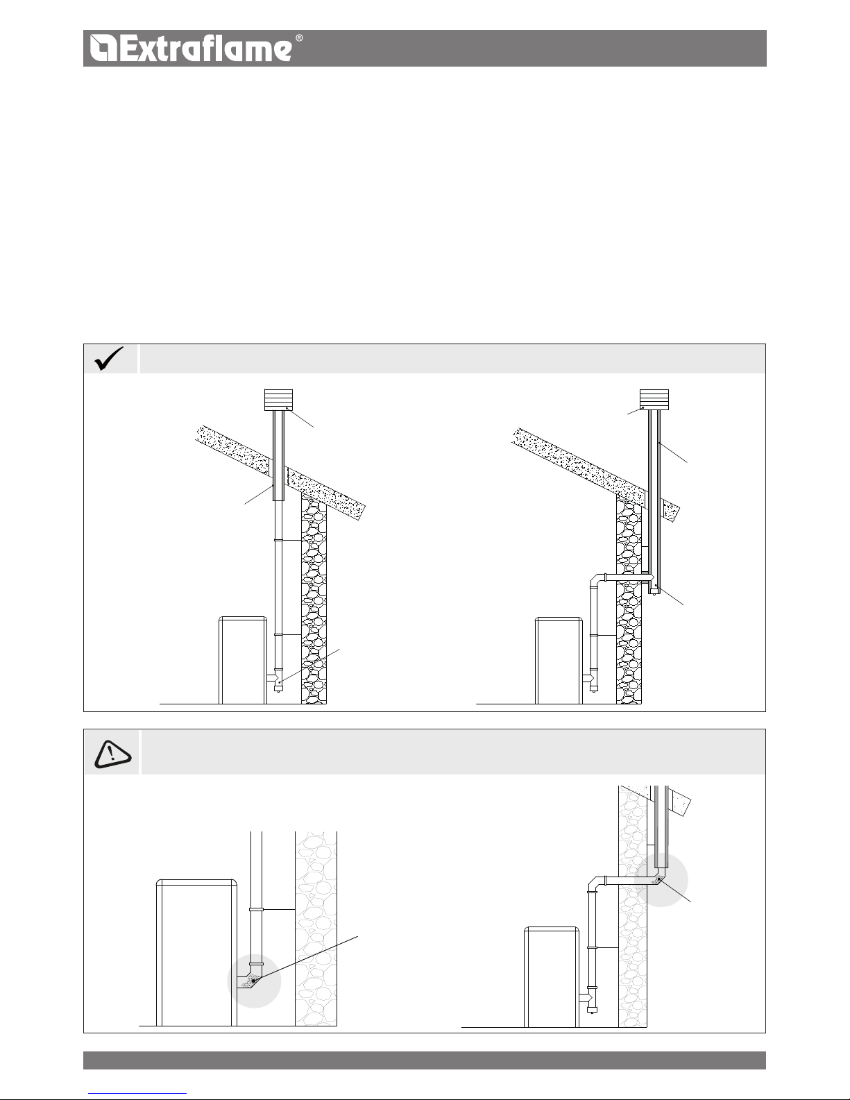
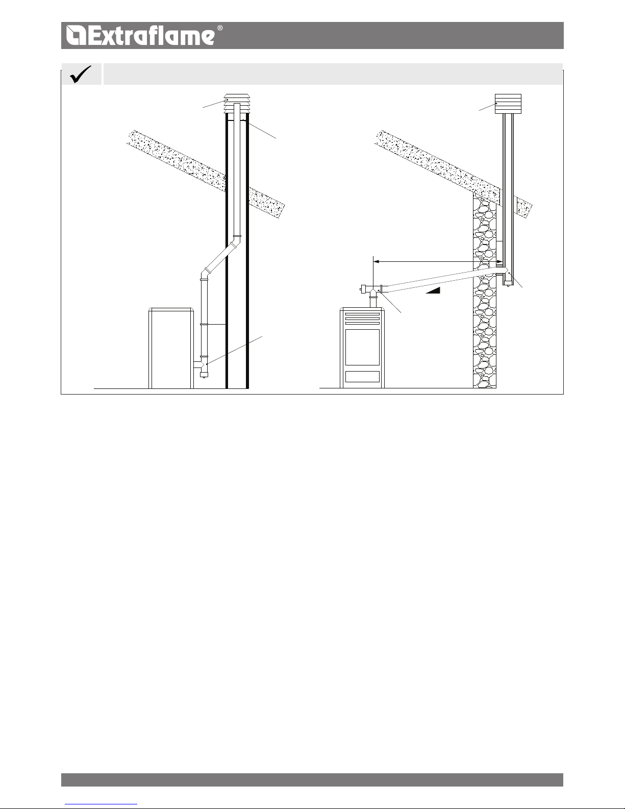
ADDITIONAL REQUIREMENTS FOR APPLIANCES FITTED WITH AN ELECTRIC FAN FOR FUMES EXPULSION
For the heat generator appliances equipped with electric fan for expelling fumes, the instructions below must be followed:
The horizontal sections must have a minimum upward slope of 3%
The length of the horizontal section must be minimal and, in any case, no longer than 3 metres
The number of direction changes including the one due to the use of the "T" element must not be more than 4.
Ash deposited in
the 90° bend
Ash deposited in
the 90° bend
Installation with internal ue
Protection from
rain and wind
Protection from
rain and wind
Insulated ue
Insulated
condensationproof "T" tting
with inspection
plug
Condensation-proof
"T" tting with
inspection plug
Insulated ue
Installation with internal - external
ue
IT IS NOT RECOMMENDED TO INSTALL A 90° BEND AS THE FIRST INITIAL PART, SINCE THE ASH WOULD BLOCK THE
PASSAGE OF THE FUMES IN A SHORT TIME, CAUSING PROBLEMS TO THE GENERATOR DRAUGHT.:
EXAMPLES OF CORRECT CONNECTION TO THE CHIMNEY
10
3 - 5%
Max 3 mt
ENGLISH
It is mandatory to use airtight pipes.
CHIMNEY
In addition to the general requirements, the chimneys for releasing combustion products into the atmosphere must:
operate under negative pressure (operation under positive pressure is not allowed);
have a preferably circular internal section; square or rectangular sections must have rounded corners with a radius of no
less than 20 mm (hydraulically equivalent sections may be used, as long as the ratio between the longer side and the shorter
side of the rectangle, which circumscribes the section, is in any case no greater than 1.5);
be designed for fumes be designed for fumes expulsion;
be predominantly vertical and have no narrowing along their entire length;
have no more than two direction changes with a slope angle no greater than 45°;
be tted with, in the event of operating in damp conditions, a device for reux drainage (condensation, rainwater);
Ducted system
A ducted system can be installed with one or more ducts, operating only with negative pressure with respect to the environment.
The exible hose compliant with UNI EN 1856-2, with T400-G characteristics, meets the requirements.
CHIMNEY CAPS
The chimney caps must meet the following requirements:
they must have a useful outlet section no less than double of that of the chimney/ducted system on which it is installed;
they must be adapted in order to prevent the penetration of rain and snow in the chimney/ducted system;
they must be built so that, in the event of winds coming from all directions and from any angle, the expulsion of combustion
products is in any case ensured;
they must be free from mechanical intake aids.
"T" tting with
inspection
plug
Steel plate,
airtight
Insulated "T"
tting with
inspection plug
Protection from rain
and wind
Protection from rain
and wind
"T" tting with
inspection plug
EXAMPLES OF CORRECT CONNECTION TO THE CHIMNEY
11

90°
c
a
ß
ENGLISH
The outlet of a chimney/ducted system must not be near obstacles that may create turbulence areas and/or prevent proper
expulsion of combustion products and maintenance operations to be carried out on the roof.
Verify the presence of other chimney caps or skylights and dormers.
FUMES EXHAUST SYSTEM PRODUCT REQUIREMENTS
Temperature class
In the event of a pellet appliance, temperature classes below T200 are not allowed.
Soot re resistance class
The fumes exhaust system interlocked with appliances supplied by solid fuels require soot re resistance, and the specication
must be indicated by the letter G followed by the distance from combustible materials in millimeters (XX) (in compliance with
UNI EN 1443) .
In the event of pellet appliances, the fumes exhaust systems must be airtight; if double designation elements are used (G and
O, with or without seal elastomer) for connecting the appliance to the chimney, one must comply with the minimum distance
XX in millimeters, indicated for designation G; in the event of re due to soot, one must ensure the restoration of the initial
conditions (by replacing the gaskets and damaged items and cleaning those remaining in use).
Ignition tests
Operation of the appliance must be veried with an ignition test, i.e.:
for mechanical feed appliances, one must complete the ignition test, verify proper operation for at least the next 15
minutes and adjust the switch-o;
For appliances installed in a hot water heating system (closed replaces, thermo-stoves), testing must also extend to the entire
hydraulic circuit.
COMBUSTION PRODUCTS OUTLET QUOTA
The outlet quota is determined by measuring the minimum height between the roof covering and the lower point of the fumes
expulsion section into the atmosphere; this quota must be outside the reux area and at an adequate distance from obstacles
which hinder or make the expulsion of the combustion products dicult or from openings or accessible areas.
Reux area
The outlet quota must be outside the reux area calculated according to the indications below.
Near the ridge one considers the lowest between the two.
Buer area for outlet quota
Clear area for outlet quota above the roof slope ( ß >10°)
REFERENCE DESCRIPTION CLEAR AREA MM
c Distance measured at 90° from the roof surface 1300
a Height above the ridge of the roof 500
12
ENGLISH
Coverings and nishings
The coverings and nishings must only be applied after having veried the proper operation of the appliance according to the
indicated modalities
TECHNICAL INSTALLATION DOCUMENTATION
When installation is complete, the installer must provide the owner or person acting for him, according to the legislation in
force, with the declaration of conformity, supplied with:
1) the use and maintenance manual of the appliance and of the system components (such as for example, the smoke ducts,
chimney, etc.);
2) photocopy or photograph of the chimney plaque;
3) system booklet (where applicable).
The installer must ask to be issued with a receipt stating that the documentation has been provided, and must keep it with a copy of
the technical documentation relating to the installation.
Installation performed by several parties
If the individual installation steps are carried out by dierent parties, each must document the work carried out for the customer
and the for the operator working on the next step.
INSPECTION AND MAINTENANCE
Frequency of operations
Maintenance of the heating system and of the appliance must be carried out on a regular basis according to the table below:
TYPE OF APPLIANCE INSTALLED <15kW (15- 35) kW
Pellet operated appliance 1 year 1 year
Water operated appliances
(closed replaces, thermo-stoves, thermo-kitchens)
1 year 1 year
Boilers 1 year 1 year
Fumes exhaust system 4 t of fuel used 4 t of fuel used
For further details refer to the "cleaning and maintenance" chapter.
Inspection and maintenance report
At the end of the inspection and/or maintenance operations, a report must be issued and released to the owner, or person
acting for him, who must conrm its receipt in writing. The report must indicate the situations encountered, the action taken,
any components replaced or installed and any comments, recommendations and requirements.
The report must be kept with the relative documentation.
In the inspection and maintenance report one must mention:
anomalies detected that cannot be removed, which pose a risk to the safety of the user or serious damage to building;
components that have been tampered with.
If anomalies as per above were detected, the owner, or person acting for him, must be warned in writing, in the maintenance
report, to refrain from using the system until the safety conditions have been fully restored.
The inspection and maintenance report must include the main information of the technician or company who performed the
inspection and/or maintenance operations, with their contact details, date of intervention and the signature of the operator.
13
ENGLISH
HOT AIR DUCTING
The pipe used for ducting the hot air must have an internal diameter of 80 mm, be insulated and protected against heat loss.
INsTAllATION Of THe RelevANT pIpes UseD fOR DUCTING THe HOT AIR mUsT be peRfORmeD by
qUAlIfIeD sTAff AND/OR THe mANUfACTUReR's TeCHNICAl AfTeR-sAles AssIsTANCe
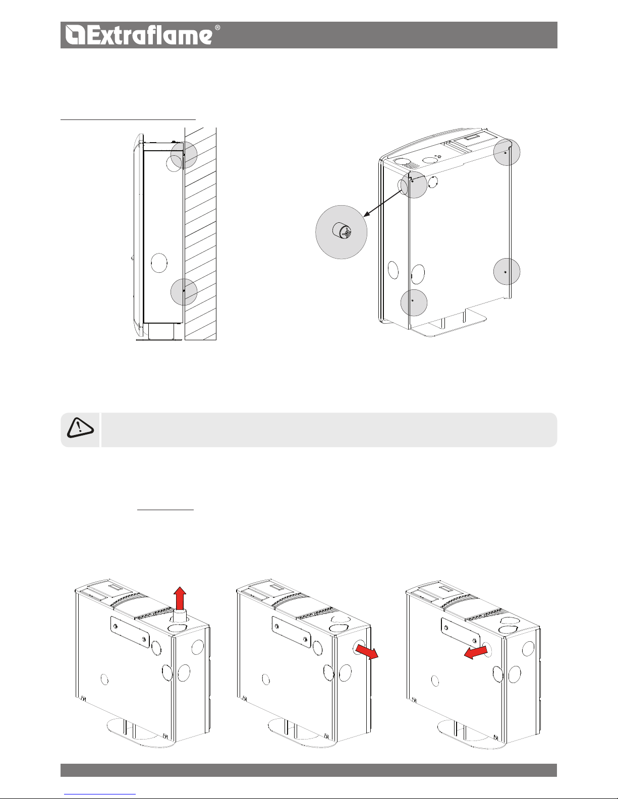
sOUveNIR AND IleNIA spACeRs
Models “SOUVENIR” and "ILENIA" feature 4 spacers at the back which delimit the minimum distance to be maintained from any
rear support.
The spacers must not be removed.
elIsIR
The “Elisir” model can be ducted at the back, to the side or at the top, for further details
relating to installation, refer to the instruction sheet included in the machine.
It is possible to use single ducting as required.
Features:
ducting outlet diameter: 80 mm
maximum recommended ducting length 6m
possibility to thermostat the ducting via an additional thermostat (option)
possibility to adjust the ventilation speed in percentage, ducting cannot be excluded.
14
3
2
1
ENGLISH
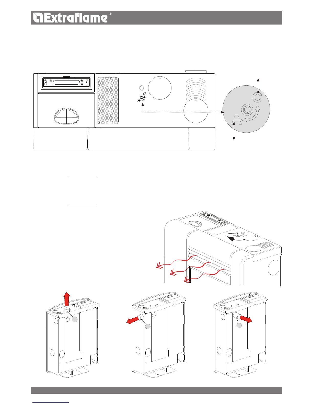
sOUveNIR - IleNIA
Models “SOUVENIR” and "ILENIA" can be ducted at the back (1), to the side (2) or at the top (3), for further details relating to
installation refer to the instruction sheet included in the machine.
There is the possibility to decide when to use the ducting by manually diverting the hot air ow, using a key, supplied, which
can be inserted in the relevant housing located on the upper part of the stove.
Features:
ducting outlet diameter: 80 mm
maximum recommended ducting length 6m
it is not possible to thermostat the ducting
possibility to adjust the fan speed in percentage.
DUCTING INTO THE
ROOM
POSITION "C"
- SOUVENIR
By turning it counterclockwise (position "C") part of the air is conveyed into the ducting, by turning it clockwise
(position "A") the ducting is conveyed into the room.
It is possible to use single ducting as required.
- ILENIA
By turning it counterclockwise (position "C") the air is conveyed into the ducting, by turning it clockwise
(position "A") the air is conveyed into the room.
It is possible to use single ducting as required.
POSITION "A"
15
 Loading...