

Page 1

PELLET STOVES
Instruction Manual
Ecologica Idro
Read these instructions carefully before installation, use and maintenance.
The instruction booklet is an integral part of the product.
Page 2

Page
2
Congratulations! You are now the owner of an EXTRAFLAME stove!
The EXTRAFLAME pellet stove is an ideal heating solution. It utilises the most advanced
technology and is manufactured to the highest standards with a contemporary design,
allowing you to enjoy the ambience and warmth of a natural flame in complete safety.
This manual tells you how to use your stove correctly. Please read the entire manual
carefully before using your stove.
IMPORTANT
Make sure that the dealer completes the following box with the details of the authorised
specialist who will help you if you have any problems in using your new pellet stove.
AUTHORISED SPECIALIST
COMPANY________________________________________________________________
NAME _______________________________________________________________
ADDRESS _____________________________________________________________
POST CODE ____________ CITY ____________________________________________
TEL. ________________________ FAX _______________________________________
All Extraflame products are manufactured according to the following directives:
•
89/106 EEC (CPD) construction materials
•
73/23 EEC (LVD) electrical safety
•
98/37 EEC machinery
•
2004/108 EEC (EMC) electromagnetic compatibility
And the following standards:
•
EN14785
•
EN60335.1 EN50165 EN50366
•
EN292 EN294
•
EN55014.1 EN55014.2 EN61000-3-2 EN61000-3-3
Page 3

Page
3
Contents
1 WARNINGS AND SAFETY 4
2 TECHNICAL SPECIFICATIONS 5
3 WHAT ARE PELLETS? 7
3.1 Pellet storage 7
3.2 Pellet loading 7
4 SAFETY DEVICES 8
4.1 Breakdown of hot air distribution fan 8
4.2 Breakdown of flue gas extractor 8
4.3 Breakdown of pellet load motor 8
4.4 Failed ignition 8
4.5 Temporary power cut 8
4.6 Electrical safety device 8
4.7 Flue gas exhaust safety device 8
4.8 Pellet temperature safety device 8
4.9 System pressure safety device 8
4.10 Boiling water safety device 8
4.11 External devices 8
4.12 Installation and safety devices 9
4.13 Safety devices for open tank systems 9
4.14 Safety devices for closed tank systems 9
5 ASSEMBLY AND INSTALLATION INSTRUCTIONS 10
5.1 Glossary 10
5.2 Installation 11
5.2.1 Connection to the flue gas evacuation system 12
5.2.2 Chimney or flue 13
5.2.3 Connecting the appliance to the flue and evacuation of combustion products 15
5.2.4 Chimney 15
5.2.5 Connection to external air inlets 16
5.2.6 Insulation, trims, facings and safety recommendations 16
5.2.7 National, regional, provincial and municipal regulations 16
6 CONTROL PANEL 17
7 ADJUSTING CURRENT TIME 18
8 USE 18
9 IGNITION 18
10 STOVE OPERATION 19
10.1 Normal operation 19
10.2 Switching-off 19
10.3 Remote control 20
11 ROOM THERMOSTAT 21
11.1 Digital thermostat (standard) 21
11.2 Mechanical thermostat (optional) 21
11.2.1 Installation of mechanical thermostat (optional) 21
11.2.2 Mechanical thermostat operation 21
11.2.3 Mechanical thermostat operation in Stby mode (to be used with remote actuator) 21
12 USER PARAMETERS 23
12.1 Water temperature adjustment 23
12.2 Weekly programmer 23
12.3 Day/night temperature function 26
12.4 Pellet load adjustment 28
13 CLEANING 29
13.1 Connection to the chimney 30
14 WIRING DIAGRAM 31
15 STOVE DISPLAY MESSAGE TABLES 33
16 WARRANTY 36
17 QUALITY CONTROL 38
18 COMPATIBILITY WITH RoHS AND WEEE DIRECTIVES 39
Page 4

Page
4
1. WARNINGS AND SAFETY
The stoves produced in our factory are built with
maximum dedication to the individual components
so as to protect both the user and the installer
from accidents. Authorised personnel are therefore
advised to pay special attention to the electrical
connections, above all after any servicing
operation on the product, especially with regard to
the stripped part of the wires, which must not
protrude in any way from the terminal block to
prevent possible contact with the live parts of the
wire.
Installation must be carried out by
authorised personnel, who have to provide a
declaration of conformity of the appliance
for the purchaser, who will then be fully
responsible for the permanent installation
and consequent correct operation of the
installed product. It is necessary to bear in
mind all the national, regional, provincial
and municipal laws and regulations present
in the country in which the appliance is
installed.
Extraflame S.p.A. may not be held
responsible in the event of failure to observe
these precautions.
This instruction manual constitutes an integral part
of the product. It must always accompany the
appliance, also when it is transferred to another
owner or user or moved to another location. If the
manual gets damaged or lost, ask your local
service centre for another copy.
This stove must only be used for the applications
for which it was expressly designed.
The manufacturer declines any responsibility,
contractually or extra-contractually, for any
damage caused to persons, animals or property by
errors in installation, adjustment, and
maintenance, or by improper use.
After removing the packaging, check to make sure
that the contents are intact and complete.
If this is not the case, contact the vendor from
whom the appliance was purchased
.
The electrical components of the stove, to
guarantee correct operation, must only be
replaced with original spare parts from an
authorised service centre.
General stove maintenance must be carried out at
least once a year, scheduled sufficiently in advance
with the service centre.
The following safety precautions must be
observed:
Do not allow the stove to be used by children or
unassisted disabled persons.
Do not touch the stove if you are bare-footed or if
parts of your body are wet or damp.
Modifying the safety or adjustment devices without
the manufacturer’s approval or instructions is
forbidden.
Never pull, detach, or twist the electrical cables
coming out of the stove, even if it is disconnected
from the electrical power supply.
Avoid blocking up or reducing the size of the air
vents of the room in which the stove is installed.
The air vents are critical for correct combustion.
Keep the packaging materials out of the reach of
children and unassisted disabled persons.
During product operation the door of the furnace
must always be closed.
Avoid direct contact with parts of the appliance
which tend to heat up during functioning.
Check for the presence of any obstructions before
switching the appliance on following a long
standstill period.
The stove has been designed to function in any
climatic conditions (even critical), in particularly
adverse conditions (strong wind, ice) safety
systems may intervene, which switch the stove off.
If this happens, contact the after-sales service and
under no circumstances disable the safety systems.
If the flue should catch fire use suitable systems to
suffocate the flames or request help from the fire
brigade.
Page 5
Page
5
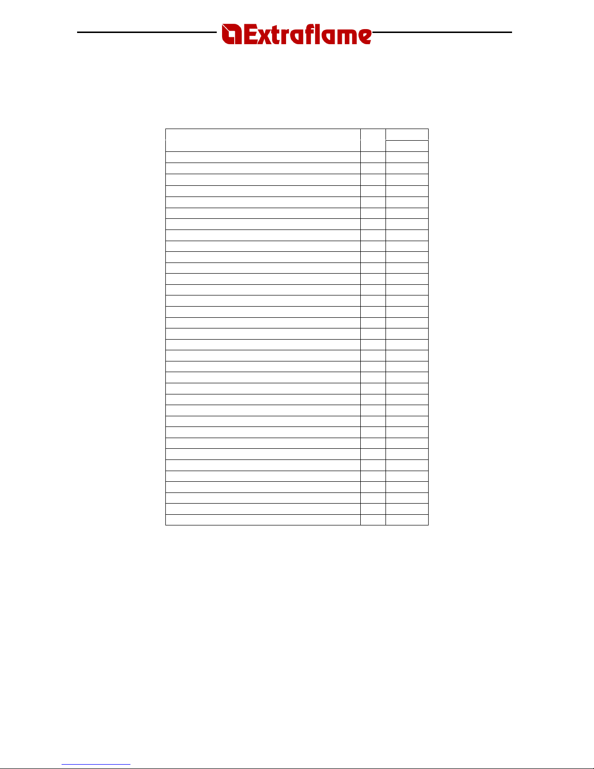
2. TECHNICAL SPECIFICATIONS
Valore
Features Unit
Value
Weight kg 159
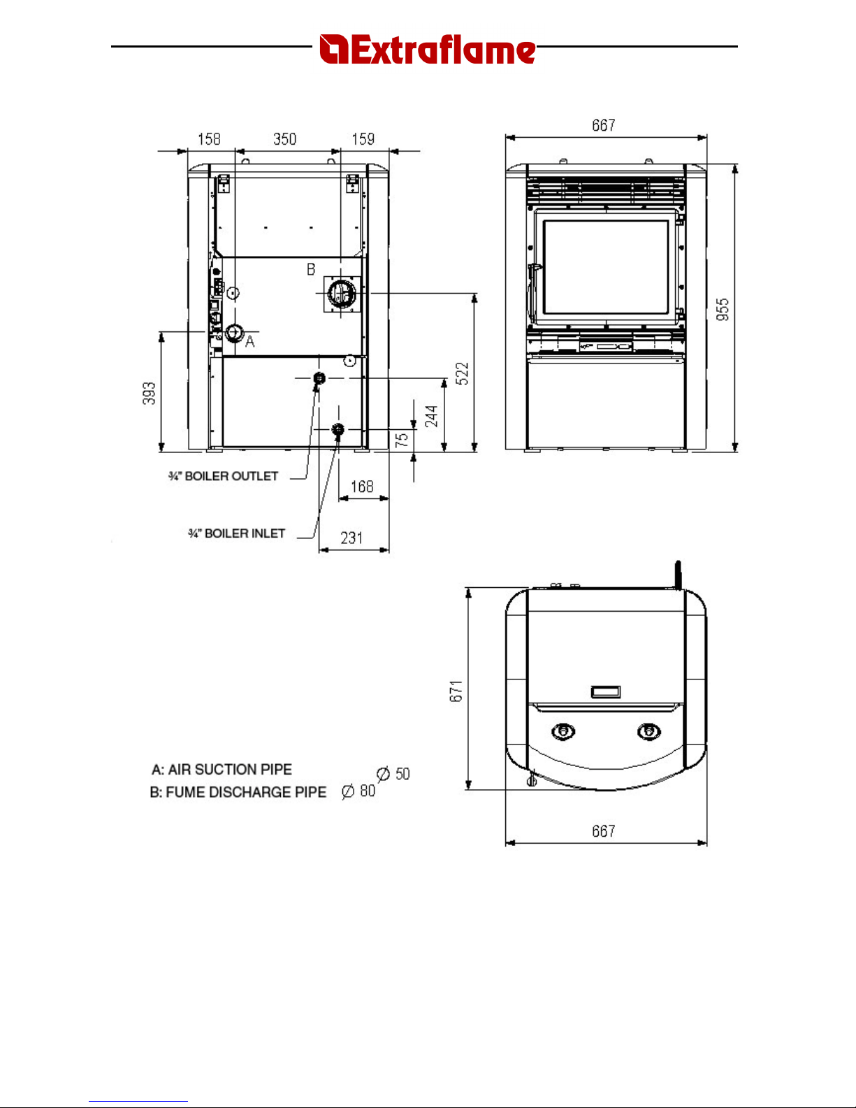
Height mm 955
Width mm 667
Depth mm 671
Flue gas exhaust pipe diameter mm 80
Air extraction pipe diameter mm 50
Max. overall thermal power kW 16
Max. useful thermal power kW 12.5
- output air power kW 1.0
- output water power kW 11.5
Min. useful thermal power kW 3.5
- output air power kW 0.5
- output water power kW 3.0
Min. hourly fuel consumption kg/h
0.8
Max. hourly fuel consumption kg/h
3.2
Tank capacity kg ~ 30
Recommended chimney draught Pa ~ 10
Chimney draught at max useful power Pa 12
Chimney draught at min useful power Pa 10
Rated electrical power W 310
Rated voltage Vac 230
Rated frequency Hz 50
Water inlet/outlet pipe diameter “ 3/4
Automatic discharge pipe diameter “ Pump head m 4
Max accepted working water power bar 1.5
CO measured at max useful power % 0.024
CO measured at min useful power % 0.033
Efficiency at max useful power % 80.8
Efficiency at min useful power % 91.5
Exhaust gas temp. at max useful power °C 214
Exhaust gas temp. at min useful power °C 76.8
Mass of gases emitted at max useful power
g/s 15.17
Mass of gases emitted at min useful power
g/s 6.38
Tests carried out using wooden pellets as fuel, with calorific value of 4.9 kW/h/kg.
The data stated above is a reference and not binding. The manufacturer reserves the right to carry
out any modifications in order to improve the performance of the product.
Page 6
Page
6
Page 7
Page
7
3. WHAT ARE PELLETS?
Pellets are made by applying very high pressure to sawdust; i.e. the residue of raw timber
(without paint) produced by sawmills, carpentry works and other activities involved in processing
wood.
This type of fuel is completely environmentally friendly, as no binders of any kind are used to keep
it compact. In fact, the compactness of the pellets over time is guaranteed by lignite, a natural
substance found in the wood itself.
As well as being an environmentally friendly fuel, since wood residues are exploited to the
maximum, pellets also have technical advantages.
While the heating power of wood is 4.4 kW/kg (with 15% humidity, after about 18 months
seasoning), the power of pellets is 5.3 kW/kg.
The density of the pellet is 650kg/m3 and the water content is 8% of its weight. For this reason,
pellets do not need to be seasoned to obtain a sufficient heating yield.
The pellet used must conform to the characteristics of the following regulations:
• Ö-Norm M 7135
• DIN plus 51731
• UNI CEN/TS 14961
Extraflame recommends always using 6 mm pellets for its products.
3.1 Pellet storage
To guarantee problem-free combustion, the pellets must be stored in a dry place.
3.2 Pellet loading
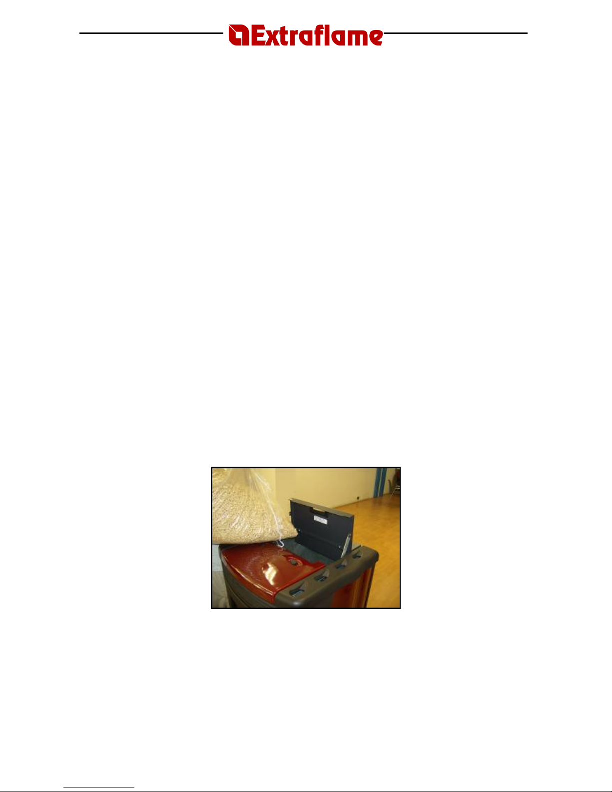
To load the pellets, open the tank cover positioned on the upper part of the stove and empty the
bag of pellets, paying attention not to let them escape.
WARNING
THE USE OF POOR QUALITY PELLETS OR ANY OTHER MATERIAL MAY DAMAGE YOUR STOVE
AND MAY LEAD TO THE INVALIDATION OF THE WARRANTY AND THE RELATED
RESPONSIBILITIES OF THE MANUFACTURER.
Page 8

Page
8
4. SAFETY DEVICES
4.1 Breakdown of hot air distribution fan
If the blower stops for any reason, the stove automatically shuts down to prevent overheating
4.2 Breakdown of flue gas extractor
If the extractor stops, the electronic unit immediately prevents pellet feeding.
4.3 Breakdown of pellet load motor
If the motor stops, the stove continues to operate until the minimum cooling level is reached.
4.4 Failed ignition
If no flame develops during the ignition phase, the appliance automatically attempts a new ignition, this
time, though, without loading pellets.
If, after this attempt, the stove still has no flame, the stove display shows “FAILED IGNITION”. If you
attempt to light the stove again, the display shows “COOLING WAIT” which means “WAIT”.
This function reminds you that before lighting the stove, you must be sure that the brazier is
free of dirt and debris.
4.5 Temporary power cut
The appliance will re-light automatically after a brief power failure. When the power goes off, the stove may
emit a minute quantity of smoke inside the house for a period of 3 to 5 minutes.
THIS DOES NOT POSE ANY SAFETY RISK.
4.6 Electrical safety device
The stove is protected against violent changes in power by a master fuse on the rear of the stove (2A 250V
delayed).
4.7 Flue gas exhaust safety device
If the exhaust system fails, an electronic pressure switch stops the stove and an alarm is signalled.
4.8 Pellet temperature safety device
In case of overheating inside the pellet tank, this safety device blocks stove operation; resetting is manual
and must be performed by an authorised technician.
4.9 System pressure safety device
A mechanical pressure switch blocks any over-pressure in the system.
Resetting is manual and must be carried out by an authorised technician.
4.10 Boiling water safety device
In the event of a lack or minimum quantity of water, this device blocks the pellet feed. Reset is manual and
must be carried out by an authorised technician.
4.11 External devices
During stove installation, it is MANDATORY to adapt the system with a pressure gauge for viewing the water
pressure and an automatic discharge valve calibrated at 3 bar pressure.
Page 9

Page
9
4.12 Installation and safety devices
The installation and respective system connections, the start-up and final testing for correct operation must
be carried out with all due diligence by authorised professional technicians (Italian Law no. 46 of 5 March
1990), in full respect for the regulations in force, both national and regional, as well as for the instructions
given in this manual.
Extraflame S.p.A. declines any responsibility for damage to objects and/or persons caused by
the system.
4.13 Safety devices for open expansion tank system
According to the UNI 10412-2 (2006) regulation, in force in Italy, systems with open expansion tank must be
equipped with:
• Open expansion tank
• Safety tube
• Loading tube
• Thermostat for circulator control (excluded for systems with natural circulation)
• Circulation system (excluded for systems with natural circulation)
• Device for acoustic alarm activation
• Acoustic alarm
• Temperature indicator
• Pressure indicator
• Automatic cut-out switch (cut-out thermostat)
The temperature safety sensors must be on-board the heat generator or at a distance no greater than 30 cm
from the delivery connection.
If the heat generators are not equipped with all the devices, the missing ones can be installed on the
delivery piping of the generator, at a distance of no more than 1 m from it.
4.14 Safety devices for closed tank system
According to the UNI 10412-2 (2006) regulation, in force in Italy, closed systems must be equipped with:
• Safety valve
• Circulator control thermostat
• Acoustic alarm activation thermostat
• Temperature indicator
• Pressure indicator
• Acoustic alarm
• Automatic thermal adjustment switch
• Automatic thermal cut-out switch (cut-out thermostat)
• Circulation system
• Expansion system
• Safety dissipation system incorporated into the generator with the blowdown valve (self-operated),
if the appliance is not equipped with a self-regulating temperature system
The temperature safety sensors must be on-board the heat generator or at a distance no greater than 30 cm
from the delivery connection.
If the generators are not equipped with all the devices, the missing ones can be installed on the delivery
piping of the generator, at a distance of no more than 1 m from the machine.
Domestic type automatic loading heating appliances must be equipped with a fuel blocking thermostat or a
cooling circuit provided by the manufacturer of the appliance, activated by a thermal safety valve in order to
guarantee that the temperature limit imposed by the regulation is not exceeded. The connection between
the power supply unit and the valve must not have interceptions. The pressure upstream from the cooling
circuit must be at least 1.5 bar.
Page 10

Page
10
5. ASSEMBLY AND INSTALLATION INSTRUCTIONS
The installation must comply with:
UNI 10683 (2005) heat generators fed with wood and other solid fuels: installation.
The chimneys must comply with:
UNI 9731 (1990) chimneys: classification according to thermal resistance.
EN 13384-1 (2006) calculation method of the thermal and fluid-dynamic features of the chimney.
UNI 7129 point 4.3.3 provisions, local rules and prescriptions of the fire brigade.
UNI 1443 (2005) chimneys: general requirements.
UNI 1457 (2004) chimneys: internal ducts in terracotta and ceramics.
5.1 Glossary
CLOSED HEARTH DEVICE
Heat generator that can only be opened to load fuel during use.
BIOMASS
Material of organic origin, excluding the material incorporated in geological formations and
fossilised.
BIOFUEL
Fuel produced directly or indirectly from biomass.
FLUE or CHIMNEY
Vertical pipe for collecting and expelling combustion products from a single appliance at a suitable
height from the floor.
EXHAUST PIPE or FITTING
Pipe or connecting element between the heat generating device and the chimney for extracting
the combustion products.
INSULATION
The series of measures taken and materials used to prevent heat transmission through a wall
dividing rooms at different temperatures.
CHIMNEY CAP
Device located at the top of the chimney that facilitates dispersion of the combustion products in
the atmosphere.
CONDENSATE
Liquid products that form when the temperature of the combustion gas is lower than or equal to
the dew point of the water.
HEAT GENERATOR
Device that permits the production of thermal energy (heat) by the rapid transformation of the
chemical energy of the fuel by means of combustion.
AIR LOCK
Mechanism for modifying the dynamic resistance of the combustion gases.
Page 11

Page
11
FLUE GAS VENTING SYSTEM
A system for flue gas exhaust venting that is independent from the appliance, composed of a pipe
or channel, chimney or single flue, and chimney cap.
FORCED DRAUGHT
Air circulation by means of a fan driven by an electric motor.
NATURAL DRAUGHT
Draught resulting in a chimney/flue due to the difference in the volume mass existing between the
(hot) fumes and the surrounding atmospheric air, without any mechanical suction aid installed
inside or on top of it.
RADIANCE AREA
Area immediately adjacent to the hearth in which the heat produced by combustion is diffused;
this area must not contain any objects made of combustible material.
REFLUX AREA
Area in which the combustion products come out from the appliance towards the room in which it
is installed.
5.2 Installation
Before carrying out installation, it is necessary to check the positioning of the chimneys, flues or
exhaust terminal ducts of the appliance, bearing in mind the following:
• Installation prohibitions
• Legal clearances
• Limitations set out by local administrative regulations or specific regulations of the
authorities.
• Common limitations deriving from building regulations, and easement or contract
regulations.
Admissible installations
In the room in which the heat generator is to be installed, any existing or installed appliances must
be airtight to the room and must not cause depression in the room with respect to the external
environment.
Appliances used for cooking foods and the related hoods without extractor can only be installed in
rooms used as kitchens.
Prohibited installations
The room in which the heat generator is to be installed must not contain any of the following
devices, either pre-existing or installed:
- Hoods with or without extractor;
- Ventilation ducts of the collective type.
Should these devices be located in adjacent rooms communicating with the installation room, it is
forbidden to use the heat generator simultaneously where there is the risk that one of the two
rooms may be subject to depression with respect to the other.
Page 12
Page
12
5.2.1 Connection to the flue gas venting system
Exhaust pipe or fitting
For the assembly of the exhaust pipes it is imperative to use non-flammable materials that are
resistant to combustion products and any condensates.
It is forbidden to use flexible metal pipes and asbestos cement for connecting the stove to the
flue, also for pre-existing exhaust channels.
There must be continuity between the exhaust pipe and the flue so that the flue does not lean on
the stove.
The exhaust pipes must not pass through rooms in which the installation of combustion devices is
forbidden.
The assembly of the exhaust pipes must be carried out in such a way as to ensure that they are
airtight for the operating conditions of the appliance, as well as to limit the formation of
condensates and prevent them from being conveyed towards the appliance.
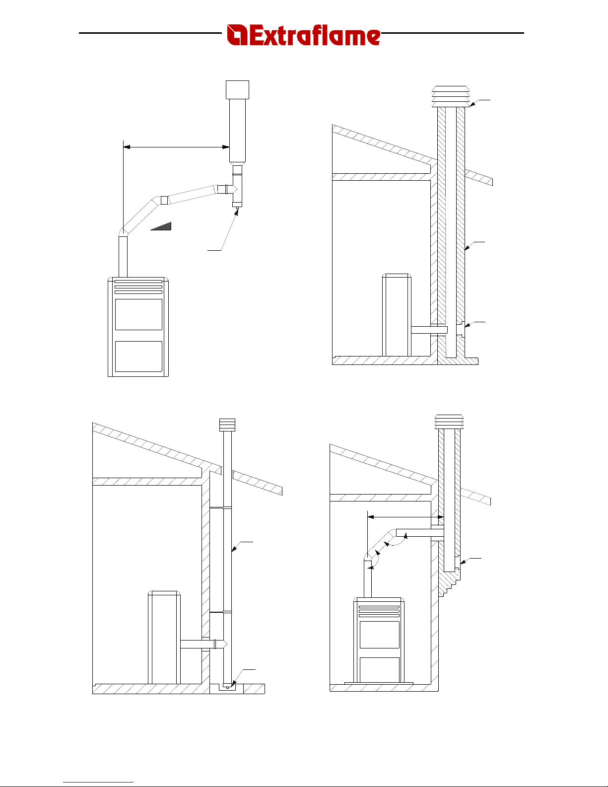
The assembly of horizontal sections must be avoided where possible.
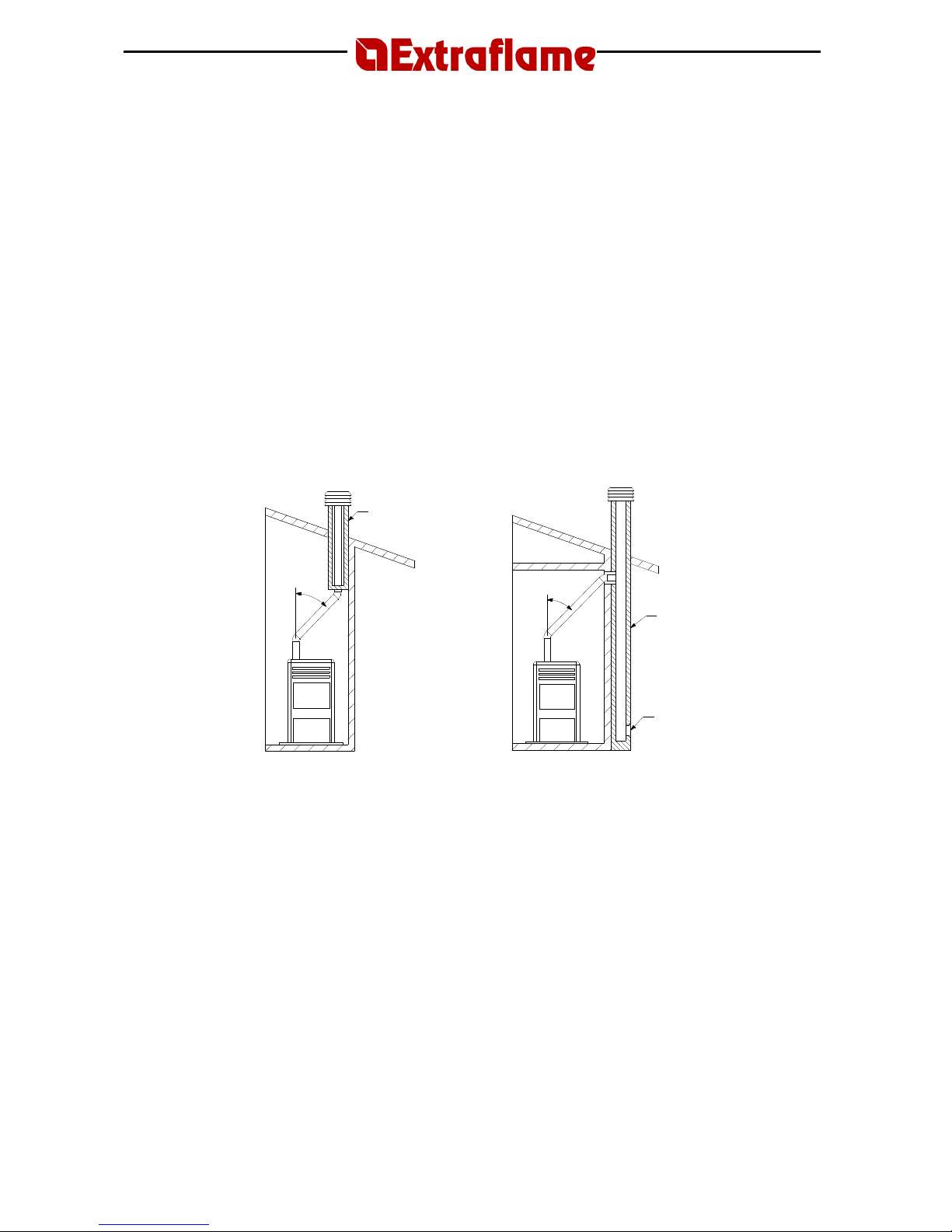
Where roof or wall exhaust outlets have to be reached that are not coaxial in relation to the
exhaust outlet from the appliance, the direction changes must be made using open elbows no
greater than 45° (see figures below).
For heat generating devices equipped with an electric exhaust fan, i.e. all products made by
Extraflame, it is necessary to observe the following instructions:
• Horizontal sections must have a minimum slope of 3% upwards.
• The length of the horizontal section must be as short as possible, and in any case no
greater than 3 metres.
• No more than four direction changes may be used, including the one resulting from the use
of the “T”-element. (When four bends are used, use double wall piping with a 100 mm
diameter.)
In any case, exhaust pipes must be sealed in relation to combustion products and condensates, as
well as insulated, if they pass outside the installation room.
It is forbidden to use elements in counter-slope.
The exhaust channel must allow soot recovery and cleaning using a swab.
The exhaust channel must have a constant cross-section. Any changes in cross-section are allowed
only at the flue connection. It is forbidden to run other air feed channels or piping for utilities
inside the exhaust channels, even if they are oversized. No manual draught regulation devices can
be mounted on forced draught appliances.
45° 45°
Insulation
Flue
Inspection
Page 13
Page
13
5.2.2 Chimney or single flue
The chimney or flue must meet the following requirements:
- be sealed to combustion products, waterproof and properly insulated according to the usage
conditions;
- be made of materials suitable to resist normal mechanical stress, as well as heat and the action
of combustion products and any condensates;
- have a predominantly vertical layout with deviations from the axis no greater than 45°;
- be situated at a proper distance from combustible or flammable materials by means of an air gap
or suitable insulation material;
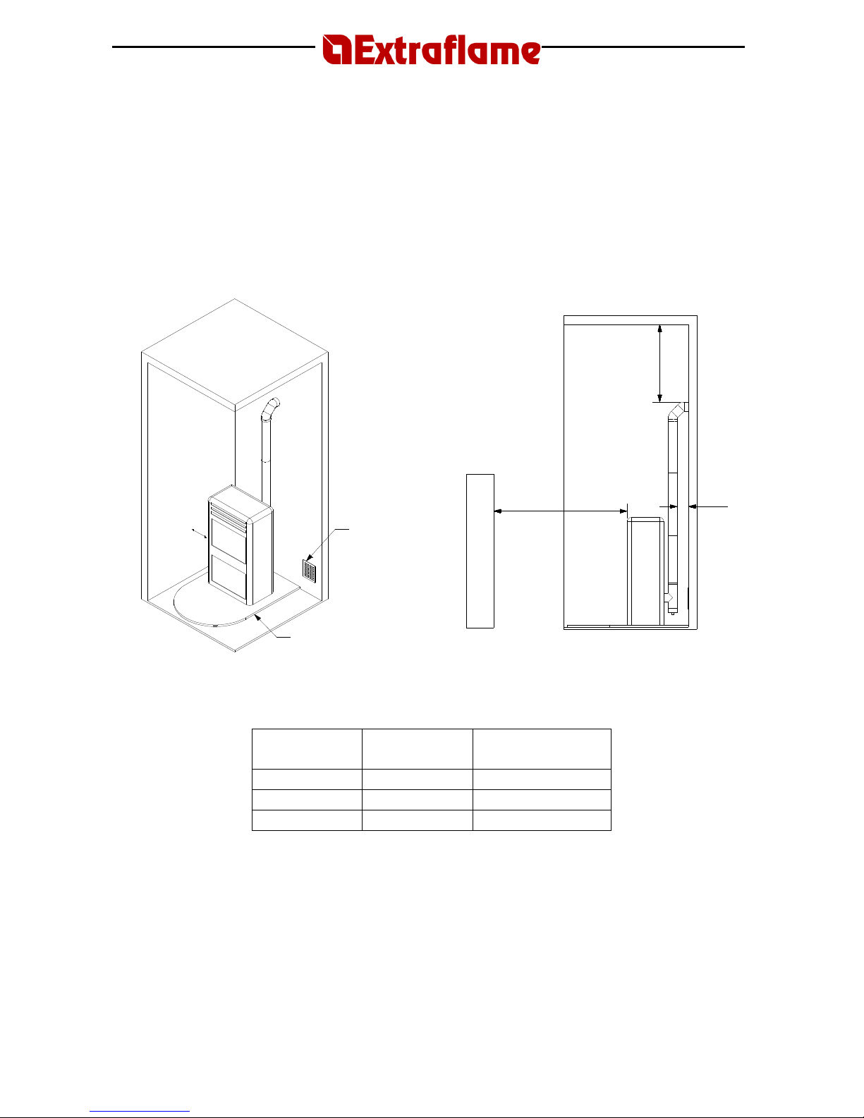
REFERENCES
Flammable
objects
Non-flammable
objects
A 200 100
B 1500 750
C 200 100
- preferably have a round internal section: square or rectangular sections must have rounded
edges with radius no less than 20 mm;
- have a constant, free and independent internal section;
- have rectangular sections with a maximum ratio between sides of 1.5.
The exhaust pipe should be equipped with a chamber for the collection of solid materials and any
condensates located below the mouth of the exhaust pipe, so that it is easy to open and inspect
from the airtight hatch.
A
Minimum 80 cm²
Flooring prote
ction
B
20 cm
C
Page 14
Page
14
Maximum 3 m
3 – 5 %
Inspection
Windproof
chimney cap
Flue
Inspection
External
insulated duct
Inspection
Maximum 3 m
45° Inspection
Page 15
Page
15
5.2.3 Connecting the appliance to the flue and evacuation of combustion products
The flue must receive exhaust from a single heat generator.
Direct discharge towards enclosed areas, even when roofless, is forbidden.
Direct discharge of combustion products must take place on the roof and the exhaust pipe must
have the features set out in the section
“Chimney or single flue”
.
5.2.4 Chimney cap
The chimney cap must meet the following requirements:
- have an internal section equivalent to that of the chimney;
- have a useful outlet section no less than twice the internal section of the chimney;
- be constructed in such a way as to prevent the penetration of rain, snow and foreign bodies into
the chimney, as well as to assure the discharge of the combustion products also in the presence of
winds coming from any direction and at any angle.
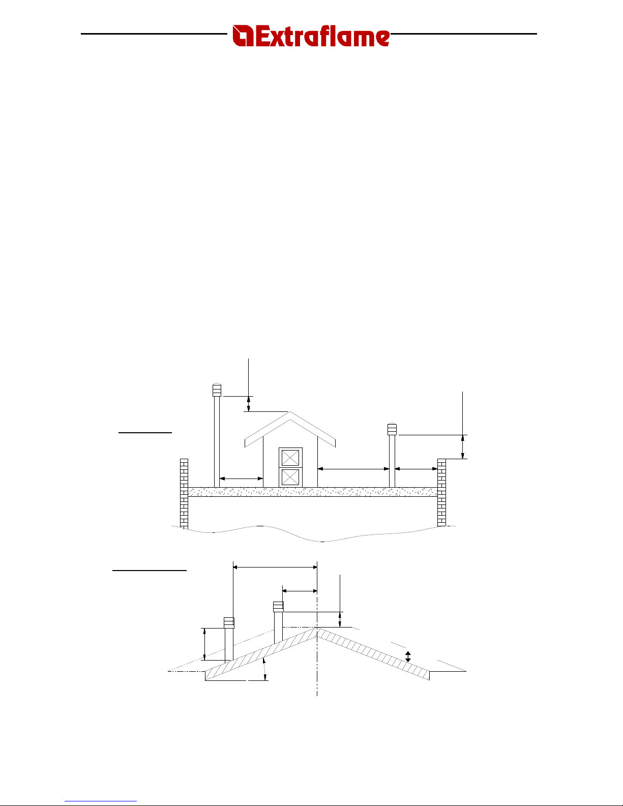
- be positioned in such a way as to assure proper dispersion and dilution of the combustion
products and, in any case, outside the reflux area in which the formation of counter-pressure is
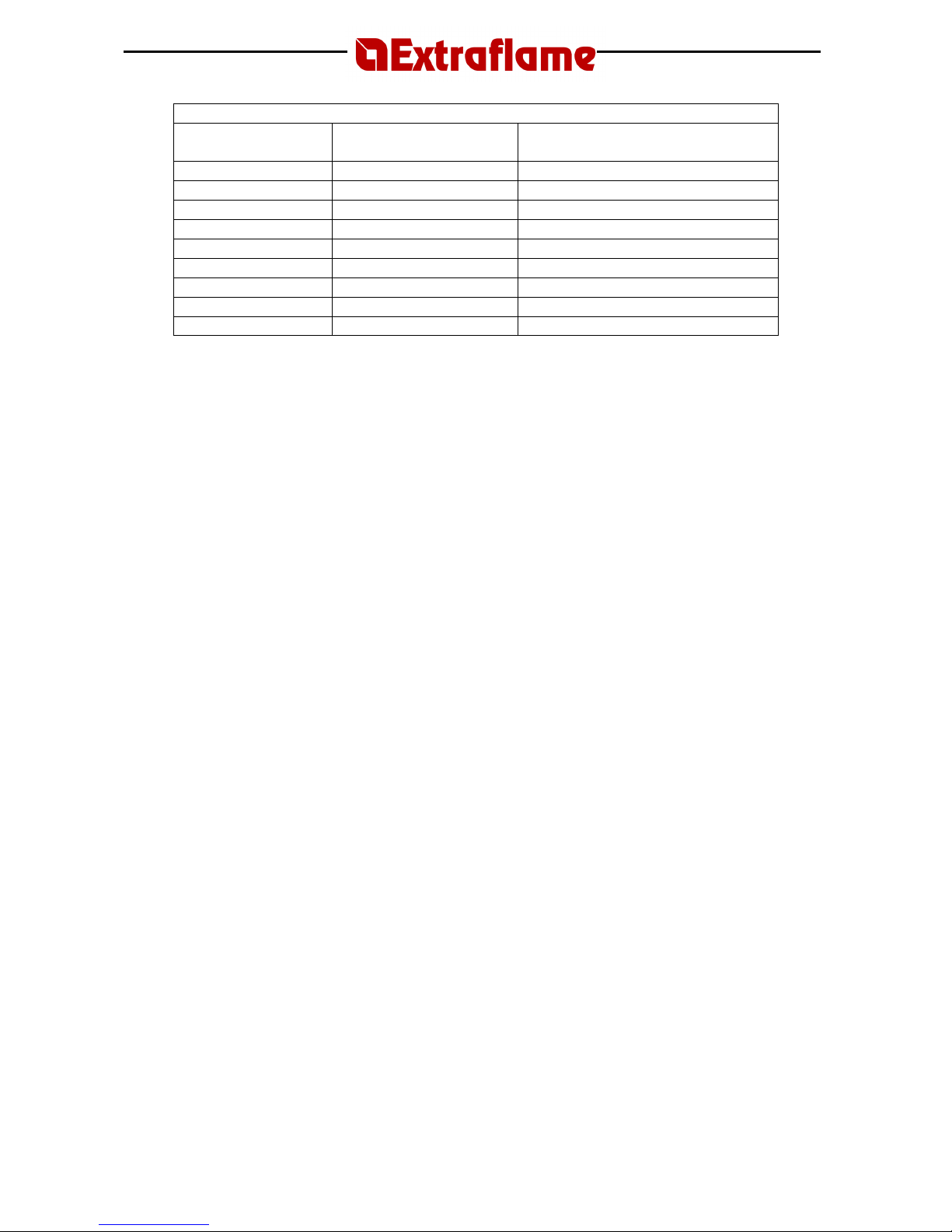
most likely to occur. This area has different sizes and shapes depending on the slope of the roof;
therefore, it is necessary to use the minimum heights indicated in the figures below.
The chimney cap must not have any mechanical suction devices.
50 cm
> 5 m
< 5 m
50 cm
< 5 m
FLAT ROOF
SLOPING ROOF
Distance
> A
Distance
< A
50 cm beyond the ridge beam
H min
β
REFLUX AREA
Reflux area height
Page 16
Page
16
CHIMNEYS, DISTANCES AND POSITIONING
Roof pitch
Distance between the
crown and the chimney
Minimum height of the chimney
(measured from the outlet)
β A (m) H (m)
15° < 1.85 0.50 m beyond the crown
> 1.85 1.00 m from the roof
30° < 1.50 0.50 m beyond the crown
> 1.50 1.30 m from the roof
45° < 1.30 0.50 m beyond the crown
> 1.30 2.00 m from the roof
60° < 1.20 0.50 m beyond the crown
> 1.20 2.60 m from the roof
5.2.5 Connection to external air inlets
To ensure correct operation, the appliance must have sufficient air available by means of external
air inlets, which must meet the following requirements:
a) They must have a total free section of at least 80 cm².
b) They must be protected by a grate, metal mesh, or other suitable protection provided that it
does not reduce the minimum section as per point a) and that it is positioned in such a way as to
prevent the intakes from being obstructed.
If the combustion air is collected directly from the outside by means of a pipe, it is necessary to fit
a downward bend or a wind hood on the outside. In addition, no grating or similar device should
be positioned. (Extraflame S.p.A. suggests creating an air intake directly communicating with the
installation room, even if air is collected from outside by means of a pipe). Air inflow can also be
obtained from a room adjacent to the installation room, provided that the flow can occur freely
through permanent openings communicating with the outside.
The adjacent room must not be subject to depression with respect to the outside as a result of the
opposing draught caused by the presence of another utility device or suction device in this room.
In the adjacent room, the permanent openings must meet the requirements described above.
The adjacent room cannot be used as a garage, storage area for combustible material, or for
activities involving fire hazards.
5.2.6 Insulation, trims, facings, and safety precautions
The facings, no matter what type of material they are made of, must constitute a self-bearing
structure with reference to the heating assembly and not in contact with it.
The beam and the trims in wood or combustible materials must be positioned outside of the
radiant area of the hearth or be properly insulated.
If the space above the heat generator has coverings made of combustible or heat-sensitive
material, a protective membrane made of non-combustible insulating material must be placed
between it and the generator.
All elements made of combustible or flammable material, such as wooden furnishings, curtains,
etc., which are directly exposed to the radiance of the hearth, must be placed at a safe distance.
The installation of the appliance must guarantee easy access for cleaning the appliance itself, of
the exhaust gas pipes and the flue.
5.2.7 National, regional, provincial and municipal laws
All the national, regional, provincial ad municipal laws of the country where the appliance has been
installed must be taken into consideration
Page 17
Page
17
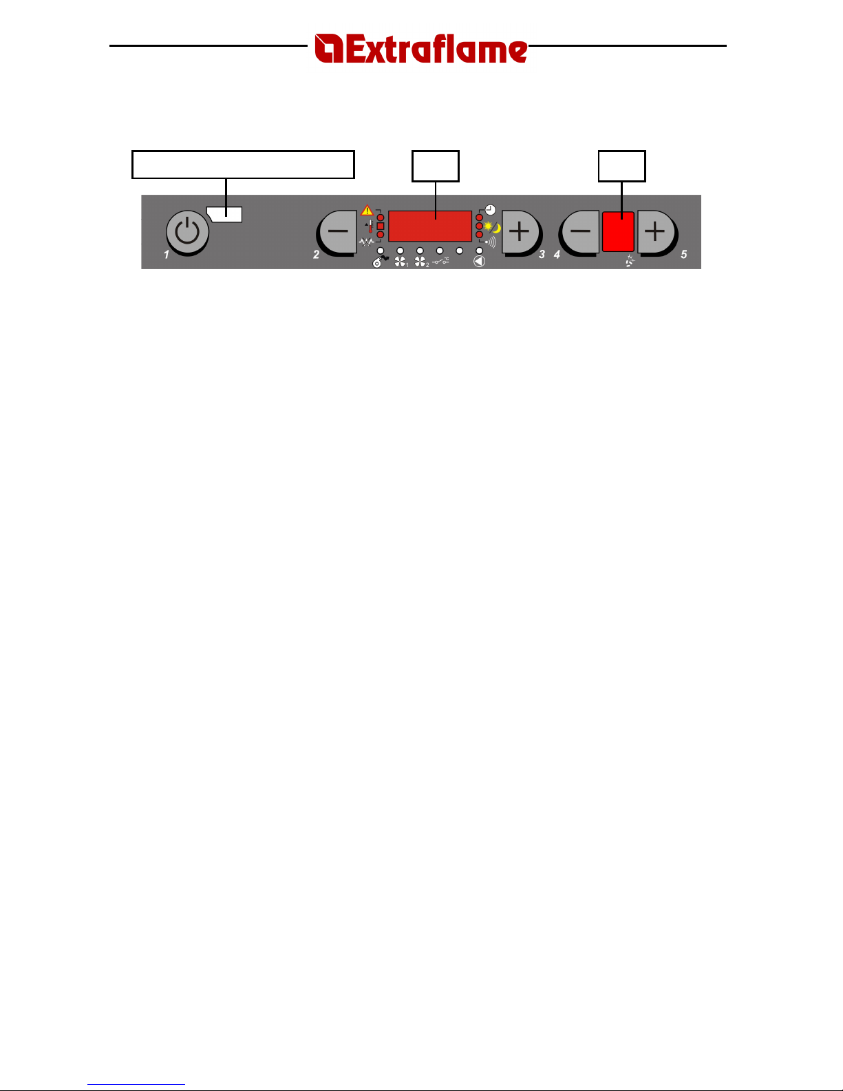
6. CONTROL PANEL
1 ON/OFF BUTTON
The stove can be turned on and off automatically by pressing button 1.
2-3 AIR TEMPERATURE SETTING
Buttons 2 and 3 are used to adjust the room temperature inside the house.
4-5 OPERATING POWER
Buttons 4 and 5 are used to adjust the heating power and warm air ventilation.
D1 Display for showing the various messages
D2 Display for showing the heat setting
REMOTE CONTROL SENSOR
D1 D2
Page 18

Page
18
7. CURRENT TIME AND DAY SETTINGS
To adjust these parameters follow the procedure below:
1. Disconnect and reconnect the power supply from the stove using the master switch or the
power cable.
2. The stove will firstly visualise the microprocessor version (Id_40 or later), “TIME”, “Li 3”
and then “OFF”.
3. When “TIME” appears, press button 5 to access the adjustment mode.
4. Display D1 will show the current time, the hours flash while the minutes are fixed: use
keys 2 and 3 to adjust the hours and then confirm using key 5.
5. At this point the hours are fixed and the minutes will start to flash: using keys 2 and 3,
adjust the minutes.
To go back to hour selection press button 4 again or exit and confirm using key 1.
8. USE
BASIC INSTRUCTIONS
The stove you have purchased uses pellets as fuel. This type of material is produced from natural
waste from woodworking. By means of a special process, which does not require the use of any
binders or additives, the shavings are compressed in industrial machines under high pressure and
become solid wooden pellets. IT IS STRICTLY FORBIDDEN to burn any other material besides
pellets in our stove.
Failure to respect these instructions will void all warranties and may jeopardise the safety of the
appliance.
The first two or three times the stove is lit, the following recommendations should be observed:
• No children should be present, as the vapours emitted can be harmful for health. Adults,
too, should not stay in the vicinity for very long.
• Do not touch the surfaces, as they could still be unstable.
• Air the room thoroughly several times.
• The hardening of the surfaces is completed after several heating processes.
• This stove must not be used as a waste incinerator.
9. IGNITION
1. Before proceeding, check to make sure that:
a. the tank is loaded with pellets
b. the combustion chamber is clean
c. the brazier is clean and free
d. the fire door and the ash drawer are sealed
e. the power cable is connected correctly
f. the two-way switch on the back of the stove is in position 1
2. Press button 1 for three seconds; display D1 will show the message “At 08”, with the
numbers decreasing every second. During this stage, the stove carries out an automatic
check on the efficiency of each single electrical component. When this cycle is completed,
display D1 shows the message Ac 15 (the number of minutes for which the stove
attempts the lighting stage, decreasing by 1 every minute that passes).
Page 19

Page
19
NOTE:
The first time the stove is used, even if the tank is loaded with pellets, it is possible
that the pellets are not distributed to the combustion chamber for the first 15 minutes
because the worm screw for loading the pellets is empty. If the stove has not developed a
flame after the fifteen minutes have elapsed, the display shows the message “NO ACC”.
In this case, press button 1 for three seconds until D1 shows the message “OFF”. Then
repeat steps 1 and 2.
3. If steps 1 and 2 are carried out correctly, as soon as the flame develops the stove enters
the start-up phase (“Au 07”).
4. After the start-up phase, the stove goes into normal operation: display D1 shows the room
temperature and D2 shows the heat setting.
WARNING!
1. NEVER USE FLAMMABLE LIQUIDS FOR LIGHTING.
2. WHEN FILLING, DO NOT BRING THE SACK OF PELLETS INTO CONTACT WITH THE
HOT STOVE.
N.B.: In the event of continued lighting failures, contact an authorised technician.
10. STOVE OPERATION
10.1
Normal operation
Once the stove is lit, you can adjust the heat setting using buttons 4 and 5. Pressing button 4
decreases the heat setting and hourly pellet consumption; pressing 5 increases them. In addition
to the feed rate, the room temperature can be set directly from the control panel using button 2
and 3. To set the water temperature of the system, see the “
Water temperature adjustment
”
chapter.
The stove adjusts itself automatically in relation to the warm air ventilation.
The contents of the tank should be monitored to prevent the flame going out due to a lack of fuel.
ATTENTION!
1. The cover of the pellet container must always be kept closed except when loading
fuel.
2. The sacks of pellets must be kept at least 1.5 metres away from the stove.
3. The tank should always be kept at least half full.
4. Before refilling, make sure that the appliance is switched off.
10.2
Shutdown
Press button 1 for three seconds.
When the three seconds have elapsed, the stove automatically starts the shutdown stage, cutting
off the pellet feed. Display D1 shows the message “OFF”, the current time, and the room
temperature in alternation.
Both the exhaust motor and warm air ventilation motor continue to run until the stove temperature
has dropped sufficiently.
Page 20
Page
20
10.3
Remote control
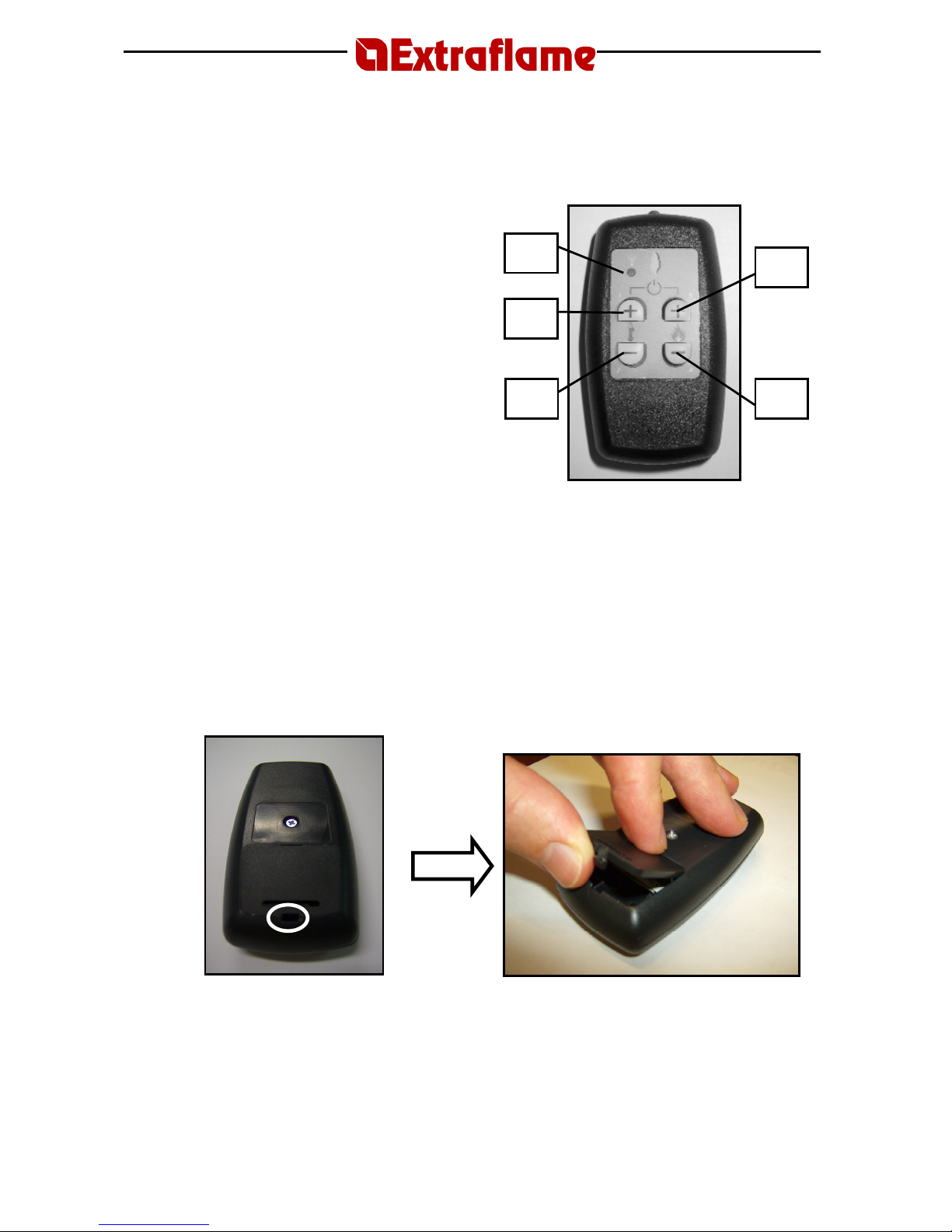
The heat setting, the room temperature, and automatic start/stop of the stove can be remote
controlled.
S = Light that indicates which keys have
been pressed.
Correspondence of display keys with
remote control keys
1 = p3+p5
2 = p2
3 = p3
4 = p4
5 = p5
To light the stove, press buttons 3 and 5 at the same time and hold for three seconds (Fig. 21);
the stove automatically enters the lighting stage. This is followed by the start-up phase, which
allows the stove to develop and settle the flame.
When the lighting stage is complete, the stove goes into normal operation. The heat setting can
be adjusted using the buttons 4 and 5, and the room temperature setting can be adjusted using
buttons 2 and 3.
To switch off the stove, press buttons 3 and 5 at the same time and hold for three seconds.
Display D1 will show the message “OFF”.
The remote control operates with an MN21 12V battery (the kind used for gate opening remote
controls).
To replace the batteries, open the cover in the rear part as illustrated below.
Open by pressing the part circled in the figure
P3
P4 P2
P5
S
Page 21

Page
21
11. ROOM THERMOSTAT
11.1
Digital thermostat (standard)
The stove can control the room temperature by means of a digital thermostat whose function is to
lower the heating power to the minimum when a pre-set temperature is reached.
1. When the stove has been started and has entered normal operating mode, a number
(e.g. 21°C ) appears on display D1 indicating the room temperature.
2. The thermostat can be set using button 2 or 3. A message appears on the display
which alternates the word “Set” with the temperature set each time one of the buttons
is pressed. Pressing 2 decreases the value and pressing 3 increases it.
3. Wait until the message “Set” disappears from the display.
4. Use buttons 4 and 5 to adjust the heat setting as desired.
When the appliance reaches the set temperature, it automatically goes to the minimum operating
condition and LED 1 on display D1 goes off.
If you wish to exclude the digital thermostat, use button 3 to set the temperature to the maximum
until “HOT” appears on display D1.
The same functions can be obtained by remote control.
11.2
Mechanical thermostat (optional)
N.B.: Installation must be carried out by an authorised technician.
A thermostat can be placed in a room adjacent to the one in which the stove is installed. Just
connect a mechanical thermostat (like those used for boilers) following the procedure described
below. (We recommend positioning the optional thermostat at a height of 1.50 m above floor
level.)
11.2.1
Installing a mechanical thermostat (optional)
N.B.: Installation must be carried out by an authorised technician.
1. Switch off the appliance using the master switch on the back of the stove.
2. Disconnect the plug from the socket.
3. Referring to the electrical wiring diagram, connect the two thermostat wires to the
respective terminals on the back side of the stove, one red and one black
11.2.2
Mechanical thermostat operation
1. Light the stove using button 1.
2. Set the desired heating power using buttons 4 and 5.
3. Bring the room temperature to minimum using button 2; the display will show “Lou”.
4. Set the desired room temperature on the thermostat (e.g. 21C°); the display will show “t
on”.
5. When the stove reaches the desired temperature, it goes to the minimum operating
condition (“Lou” appears on D1). If the temperature drops, the stove will pass to “t on”
again, returning to the setting previously made.
Page 22

Page
22
11.2.3
Mechanical thermostat operation in Standby mode (to be used also for remote
actuator)
The Standby function is used to further reduce pellet consumption by switching off the stove when
the desired temperature has been reached.
As the temperature drops, the stove will automatically switch on again.
1. Set the desired temperature using buttons 4 and 5.
2. Using button 2, set the room temperature at the minimum position until display D1 shows
“Lou” with “Set” flashing.
3. While “Lou” and “Set” are flashing, press button 1 for three seconds; the display shows
Stby, which means that the energy saving function is on.
At this point the thermostat will control the stove as described below:
• Thermostat with closed contact: the stove switches on and operates at the power set.
Display D1 shows “t on”.
• Thermostat with open contact: the stove switches off or stays off, and display D1 shows
“Stby”.
This function can also be suspended temporarily by pressing button 1 for three seconds.
• If the stove is in “Stby” phase, the stove remains off. Display D1 shows “Stby”, “off” and
the current time.
• If the stove is in “t on” phase, the stove switches off. Display D1 shows “t on”, “off” and
the current time.
To return to using this function, press button 1 again.
To exclude this function altogether, just raise the stove thermostat temperature using button 3.
Page 23
Page
23
12. USER PARAMETERS
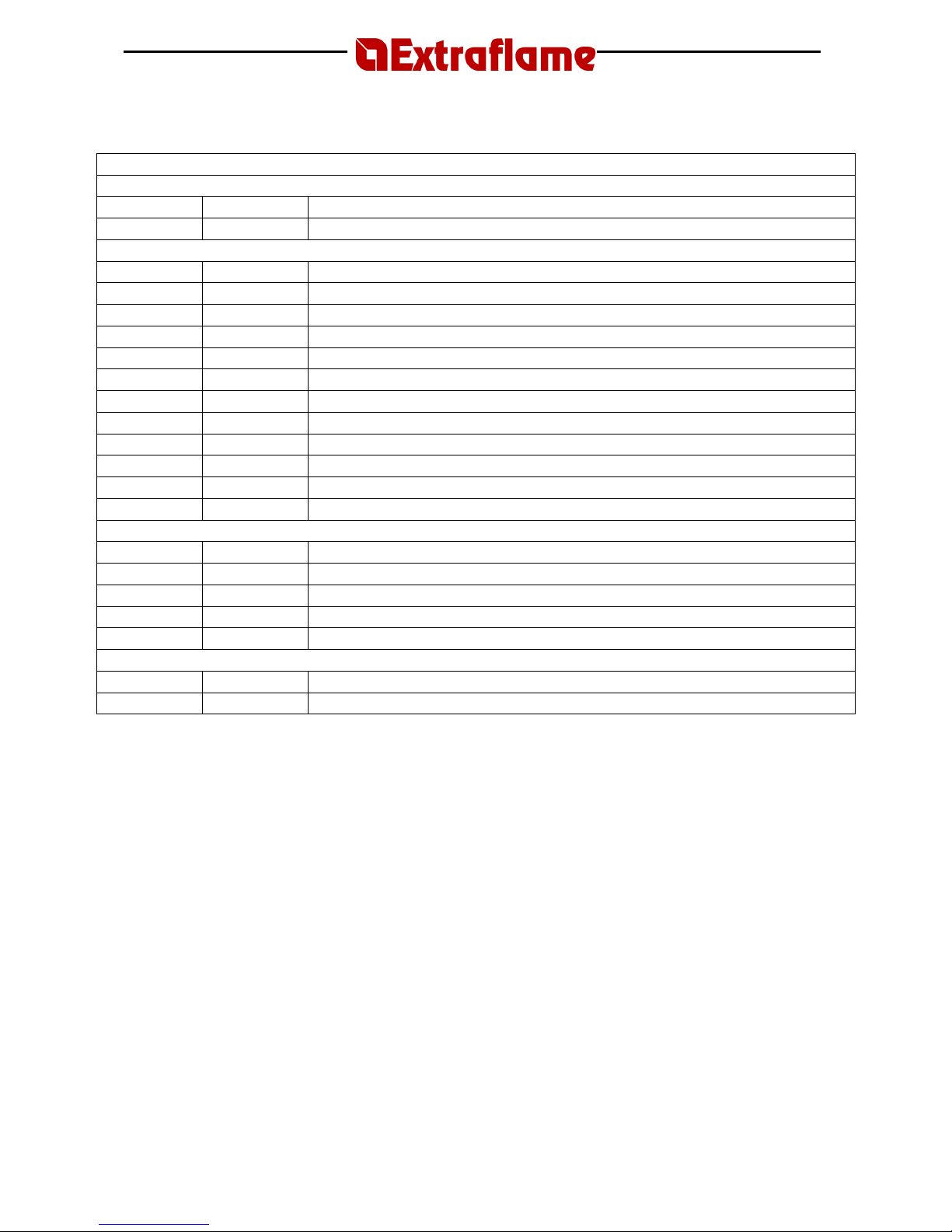
USER PARAMETERS
WATER TEMPERATURE ADJUSTMENT
Display D1 Display D2
Function
70°C Water temperature adjustment
WEEKLY PROGRAMMER
Display D1 Display D2
Function
off 0 Act./ Deact. Weekly programmer
00:00 1 1st ignition time
00:00 2 1st switch-off time
off 1 3 Consents for 1st ignition /switch-off for the various days
00 4 Installer parameter
00:00 5 2nd ignition time
00:00 6 2nd switch-off time
off 1 7 Consents for 2nd ignition/switch off for various days
00:00 8 3rd ignition time
00:00 9 3rd switch-off time
off 1 A Consents for 3rd ignition /switch-off for the various days
DAY-NIGHT TEMPERATURE FUNCTION
Display D1 Display D2
Function
06:00 B Start day period/ end night period
22:00 C Start night period/ end day period
25 D Day period max. temperature
20 E Night period max. temperature
PELLET LOAD ADJUSTMENT
Display D1 Display D2
Function
00 F % pellet load adjustment
12.1 Water temperature adjustment
This function allows the user to set the desired water temperature. Press and hold button 3 to
access this parameter, press button 5 and release the 2 keys at the same time.
In display D1 flashing “H2O” (water) and “70°C” will appear. This corresponds to the value that
can be modified while nothing appears on display D2.
Use keys 2 and 3 to adjust the desired temperature with a maximum range from 40 to 90°C. To
confirm use key 1.
12.2 Weekly programmer
The weekly programmer functions allow the user to programme 3 phases within a day to use on
all days of the week. The ignition and switch off times must be included within the span of one
day, from 0 to 24, and not overlapping several days:
E.g. ignition at 07:00 / switch-off at 18:00 OK
ignition at 22:00 / switch-off at 05:00 ERROR
Page 24
Page
24
Before programming this function, you have to set the current time using “
setting current day and
time”
in order to provide a reference for the programming function.
To access programming press and hold button 3, then press button 5 and then release the 2
buttons at the same time. Using button 5, scroll until display D2 shows “0” flashing.
The table below shows all the parameters of the weekly programmer function.
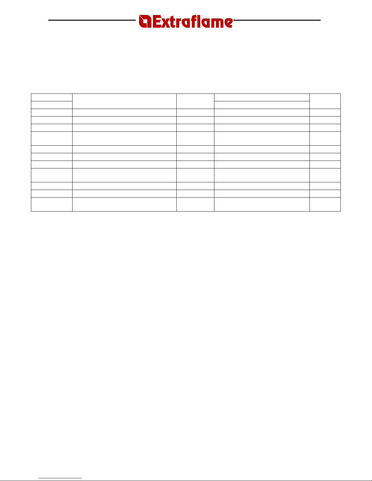
Parameter Value
Display D2
Function
Adjustment
keys
Display D1
Confirm
key
0 Act./ Deact. Weekly programmer
2 or 3 ON/OFF 5
1 1st ignition time
2 or 3 OFF or from 00:00 to 23:50 5
2 1st switch-off time
2 or 3 OFF or from 00:00 to 23:50 5
3
Consents for 1st ignition /switch-off for
the various days
2 or 3 ON/OFF 1, ON/OFF 2, … ON/OFF 7 5
4 Installer parameter
2 or 3 00 5
5 2nd ignition time 2 or 3 OFF or from 00:00 to 23:50 5
6 2nd switch-off time 2 or 3 OFF or from 00:00 to 23:50 5
7
Consents for 2nd ignition/switch off for
various days
2 or 3 ON/OFF 1, ON/OFF 2, … ON/OFF 7 5
8 3rd ignition time 2 or 3 OFF or from 00:00 to 23:50 5
9 3rd switch-off time 2 or 3 OFF or from 00:00 to 23:50 5
A
Consents for 3rd ignition /switch-off for
the various days
2 or 3 ON/OFF 1, ON/OFF 2, … ON/OFF 7 1
Let’s suppose that the weekly programmer is to be used and the 3 time periods are to be used in
the following way:
1st time period: from 08:00 to 12:00 every day of the week excluding Saturday and Sunday
2nd time period: from 15:00 to 22:00 only Saturday and Sunday
3rd time period: not used
Let’s continue with weekly programming.
Parameter 0 (D2=0(flashing); D1=on)
Using buttons 2 or 3, activate the weekly programmer, setting the value to ON.
Parameter 1 (D2=1(flashing); D1=E.g. “08:00”)
Using buttons 2 or 3, set the time “08:00” which corresponds to the switching on time of the 1st
time period. To confirm and continue programming press button 5.
To return to the previous parameter press button 4.
Parameter 2 (D2=2(flashing); D1=E.g. “12:00”)
Using buttons 2 or 3, set the time “12:00” which corresponds to the switching-off time of the 1st
time period. To confirm and continue programming press button 5.
To return to the previous parameter press button 4.
Parameter 3 (D2=3(flashing); D1= “off 1”)
Activate the 1st time period for every day of the week excluding Saturday and Sunday. To do this,
use buttons 2 and 3 in the following way:
a. button 3 – scrolls through the various days
b. button 2 – enabled/disabled(ON/OFF) the 1st time period for that day
Page 25
Page
25
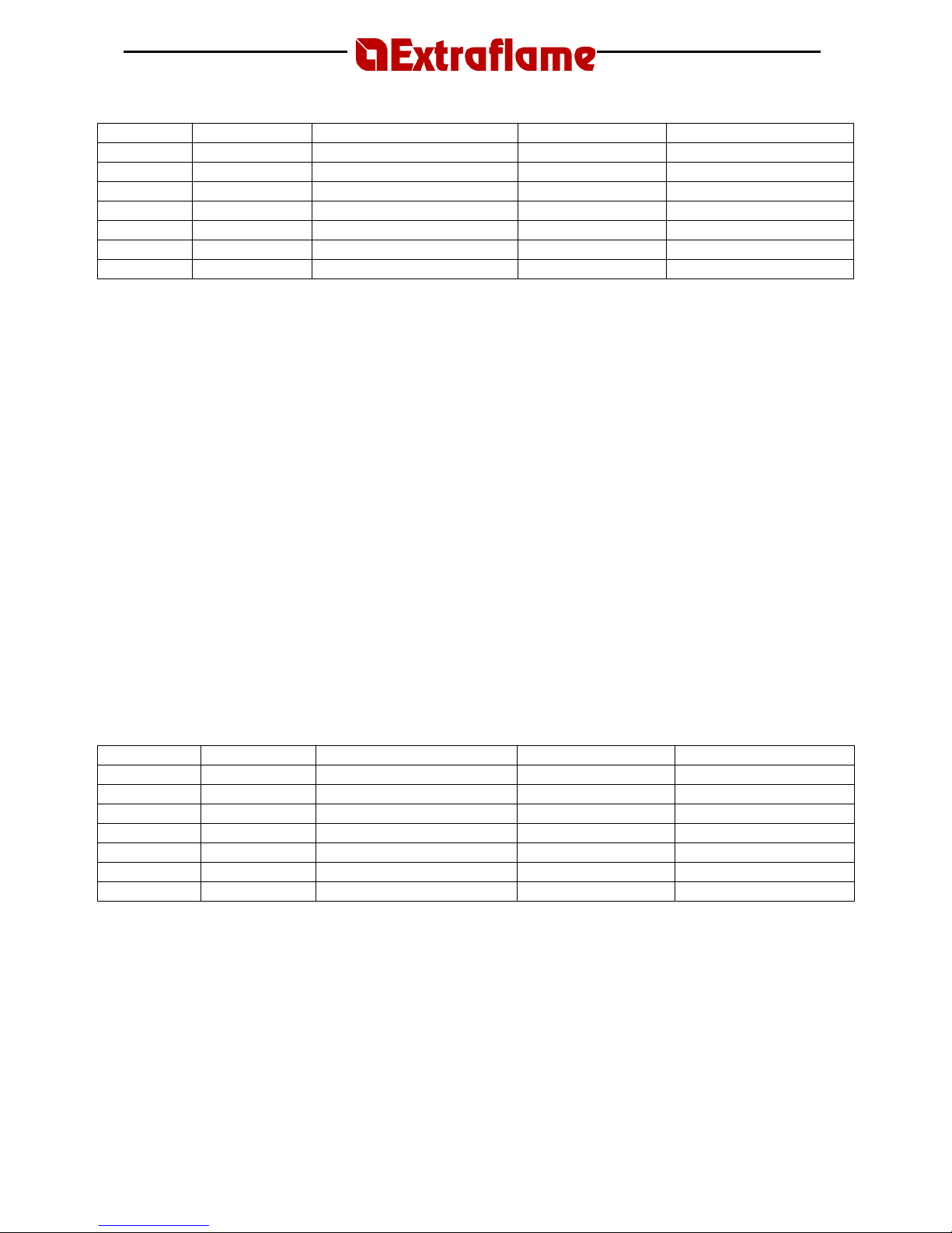
Example:
Day Initial value Function button 2 Final value Function button 3
MONDAY OFF 1
OFF 1 ON 1 and vice versa
ON 1(period active) Passes to the following day
TUESDAY OFF 2
OFF 2 ON 2 and vice versa
ON 2(period active) Passes to the following day
WEDNESDAY
OFF 3
OFF 3 ON 3 and vice versa
ON 3(period active) Passes to the following day
THURSDAY OFF 4
OFF 4 ON 4 and vice versa
ON 4(period active) Passes to the following day
FRIDAY OFF 5
OFF 5 ON 5 and vice versa
ON 5(period active) Passes to the following day
SATURDAY OFF 6
OFF 6 ON 6 and vice versa
OFF 6(period deact.) Passes to the following day
SUNDAY OFF 7
OFF 7 ON 7 and vice versa
OFF 7(period deact.) Passes to the following day
To confirm and continue programming press button 5.
To return to the previous parameter press button 4.
Parameter 4 (D2=4(flashing); D1= “00”)
N.B. This parameter reserved for the assistance service and must not be modified.
Parameter 5 (D2=5(flashing); D1=E.g. “15:00”)
Using buttons 2 or 3 set the time “15:00” which corresponds to the switching-on time of the 2nd
time period. To confirm and continue programming press button 5.
To return to the previous parameter press button 4.
Parameter 6 (D2=6(flashing); D1=E.g. “22:00”)
Using buttons 2 or 3 set the time “22:00” which corresponds to the switching-off time of the 2nd
time period. To confirm and continue programming press button 5.
To return to the previous parameter press button 4.
Parameter 7 (D2=7(flashing); D1=E.g. “off 1”)
Activate the 2
nd
time period only Saturday and Sunday. To do this, use buttons 2 and 3 in the
following way:
a. button 3 – scrolls through the various days
b. button 2 – enabled/disabled (ON/OFF) the 1st time period for that day
Example:
Day Initial value Function button 2 Final value Function button 3
MONDAY OFF 1
OFF 1 ON 1 and vice versa
ON 1(period deact.) Passes to the following day
TUESDAY OFF 2
OFF 2 ON 2 and vice versa
ON 2(period deact.) Passes to the following day
WEDNESDAY OFF 3
OFF 3 ON 3 and vice versa
ON 3(period deact.) Passes to the following day
THURSDAY OFF 4
OFF 4 ON 4 and vice versa
ON 4(period deact.) Passes to the following day
FRIDAY OFF 5
OFF 5 ON 5 and vice versa
ON 5(period deact.) Passes to the following day
SATURDAY OFF 6
OFF 6 ON 6 and vice versa
OFF 6(period active.) Passes to the following day
SUNDAY OFF 7
OFF 7 ON 7 and vice versa
OFF 7(period active) Passes to the following day
To confirm and continue programming press button 5.
To return to the previous parameter press button 4.
Parameter 8 (D2=8(flashing); D1=E.g. “off”)
Using buttons 2 or 3 set “off”, which can be found before “00:00”, in order to disable the
switching on of the 3rd time period.
To confirm and continue programming press button 5.
To return to the previous parameter press button 4.
Page 26

Page
26
Parameter 9 (D2=9(flashing); D1=E.g. “off”)
Using buttons 2 or 3 set “off”, which can be found before “00:00”, in order to disable the
switching on of the 3rd time period.
To confirm and continue programming press button 5.
To return to the previous parameter press button 4.
Parameter A (D2=A(flashing); D1=E.g. “off 1”)
At this point, the values entered in this parameter no longer have any value as both the switchingon and –off of the 3rd time period have been disabled.
To confirm and continue programming press button 5.
To return to the previous parameter press button 4.
To exit press button 1.
N.B.: When the weekly programmer is active on the control panel, the respective light will come
on (see display message table description).
TO DEACTIVATE THE WEEKLY PROGRAMMER enter in to programming mode by pressing
button 3 and holding down button 5, display D2 shows “0” flashing, and set “off” on display D1
using buttons 2 and 3. Then press button 1 to confirm and exit.
Manual commands, from the display or using remote control, are always given priority compared
to the programming.
12.3
Day/Night temperature function
The day/night temperature function makes it possible to switch the stove on/off automatically
based on two selected temperatures.
This function is particularly useful when the stove heat exceeds the setting of the room thermostat
(e.g. due to mid-season temperatures or a stove that is oversized compared to the space).
This system enables you to select one temperature for daytime and one for night.
Before programming this function, you have to set the current day and time using the “
current day
and time setting
” instructions to provide a reference for the programming function.
To access the parameters of the day/night temperature function, press button 3 and hold it down,
then press button 5 and release both buttons at the same time. When you have entered the
function, press button 5 to move to parameter b (D2= b)
Parameter b (D2 = b, D1 =Ex. “06.00” )
Press button 2 or 3 to set the day period start/night period end.
Press button 5 to confirm and go to the next parameter.
Parameter c (D2 = c, D1 =Ex. “22.00” )
Press button 2 or 3 to set the day period end/night period start.
Press button 5 to confirm and go to the next parameter.
Parameter d (D2 = d, D1 =Ex. “25°C” )
Press button 2 or 3 to set the maximum temperature for the day period.
Press button 5 to confirm and go to the next parameter.
Parameter E (D2 = e, D1 =Ex. “20°C” )
Press button 2 or 3 to set the maximum temperature for the night period.
Press button 1 to confirm and exit.
Page 27
Page
27
When you have exited from the programming, to activate/deactivate the function, press button 4
and hold it down, press button 5, then release both buttons at the same time.
The corresponding LED on the control panel will light up/go off (see description in the display
messages table).
N.B. The stove must always be shut down while setting parameters.
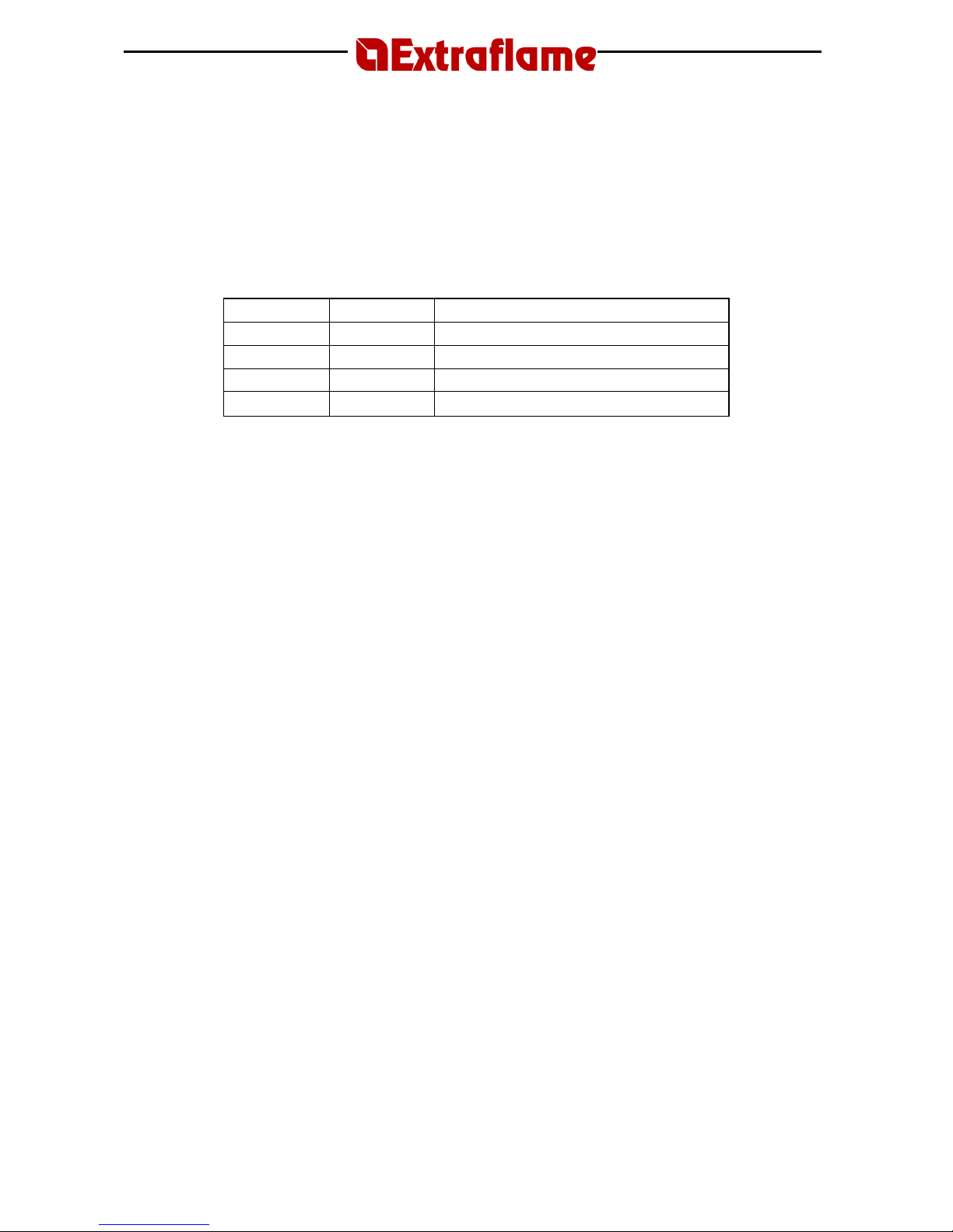
Summary table
Display D1 Display D2
Function
06:00 B
Start day phase/end night phase
22:00 C
Start night phase/end day phase
25°C D
Day phase max. temperature
20°C E
Night phase max. temperature
Once this function is active, it is still necessary to light the stove using button 1. When the stove
switches off because the maximum temperature has been reached, the message “doff” appears
on D1.The stove will switch on again automatically when the room temperature is 3°C lower than
the maximum temperature set.
e.g. Status of the stove – doff
Max. temperature set – 25°C
When the room temperature goes below 22°C (25 – 3 = 22°C), the stove will automatically start
again.
N.B.: This only occurs if the stove is in “doff” status, not in “off” status.
Manual controls via the front panel or remote control take precedence over any programmed
settings.
Page 28
Page
28
12.4
Pellet loading adjustment
If the stove has operating problems due to the quantity of pellets, you can adjust the pellet load
directly from the control panel.
Problems related to the quantity of pellets fall into one of two categories:
1
- LACK OF PELLETS
• The stove cannot develop a suitable flame, tending to burn very poorly even at high
speeds.
• At the lowest speed, the stove tends to almost burn out, causing the stove to go into “NO
PELL” alarm status.
• When “NO PELL” is displayed, there may still be some unburned pellets in the brazier.
2 - EXCESS PELLETS
• The stove develops a very high flame even at low speeds.
• The flame tends to soil the stove window, darkening it almost completely.
• The brazier tends to get incrusted, blocking the air intake holes, due to the excessive pellet
load that is only partially burned.
N.B.: If this problem occurs just a few months after installation, check to make sure that the user
is correctly carrying out the regular cleaning schedule described in the instruction manual.
The adjustment is made on a percentage basis, and therefore any change of this parameter leads
to a proportional variation on all loading speeds of the stove.
To access the percentage adjustment of pellet feeding, you have to enter the user programming
by pressing button 3, and while keeping it pressed, press button 5.
At this point use button 5 to move through the menu until you see “F” flashing on D2.
If you go beyond this parameter unintentionally, exit by pressing button 1 and repeat the
procedure.
The value “00” will be shown on D1: using buttons 2 and 3, you can set an increased/decreased
percentage at 5 point intervals (the parameter can be modified with a maximum scale from -50 to
+50).
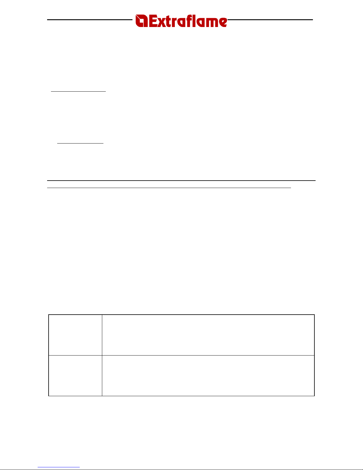
Adjustment table
LACK OF
PELLETS
Increase the percentage by 5 percent and try the stove with this new setting
for at least half an hour. If the problem is reduced but not resolved, increase
by a further 5 percent. Repeat this process until the problem is resolved.
If the problem cannot be resolved, contact the service centre.
EXCESS
PELLETS
Decrease the value by 5 percent and try the stove with this new setting for at
least half an hour. If the problem is reduced but not resolved, dec
rease by a
further 5 percent. Repeat this process until the problem is resolved.
If the problem cannot be resolved, contact the service centre.
When the final adjustment has been made, press button 1 to confirm and exit the program.
Page 29
Page
29
13. CLEANING
Maintenance operations guarantee correct functioning of the product through time.
The lack of fulfilment of these operations can jeopardise safety of the product.
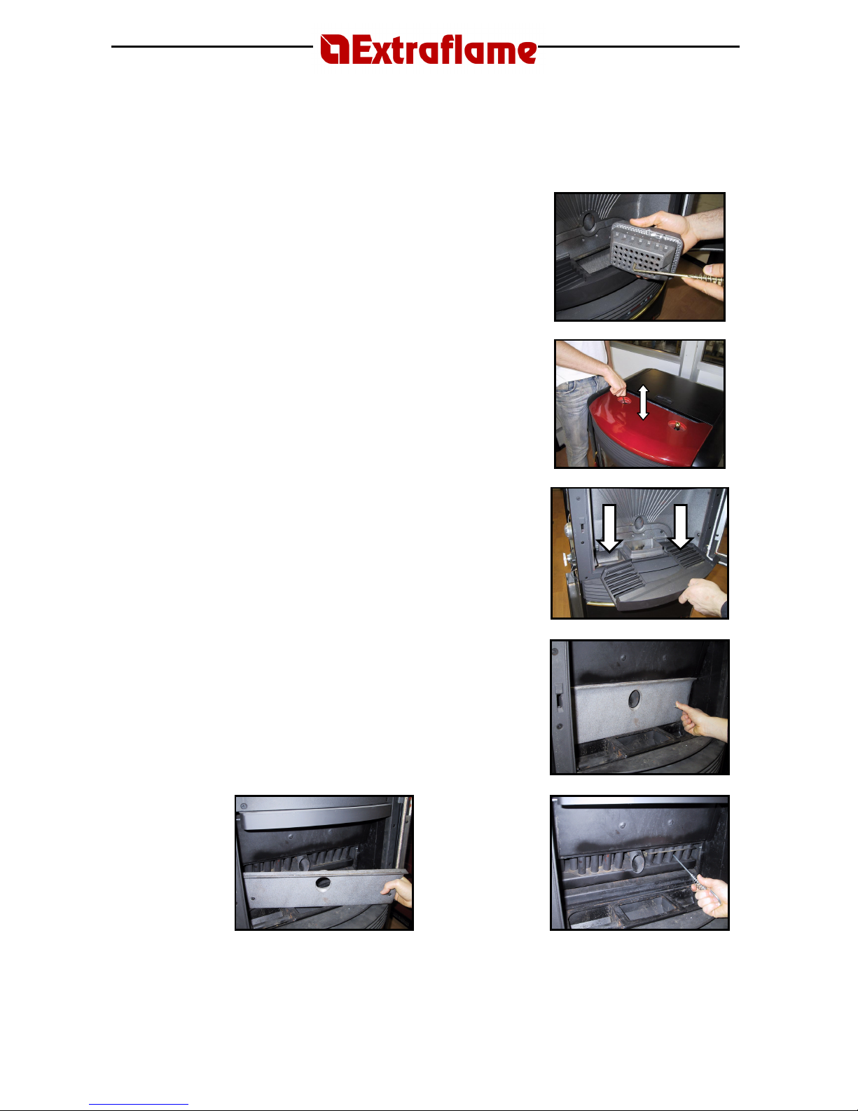
1. CLEANING THE BRAZIER
The brazier must be cleaned daily.
• Remove the brazier from its container and clean the
holes using the supplied relevant tool (see figure 1).
• Remove the ash from the brazier using a Vacuum
cleaner.
• Suck-up the ash deposited in the brazier compartment.
Figure 1
2. USE OF SCRAPERS
Cleaning the heat exchangers guarantees a constant heat yield
over time. This type of maintenance must be carried out at
least once a day. Use the relevant scrapers positioned in the
upper part of the stove, by carrying out several upward and
downward movements (see figure 2).
Figure 2
3. CLEANING OF ASH COLLECTION TANKS
The ash collection tanks must be emptied when required using
a vacuum cleaner.
Figure 3
4. CLEANING THE HEAT EXCHANGER (Weekly)
The heat exchanger chamber must be cleaned weekly. Remove
the mobile wall as illustrated in figures 4 and 5.
Once the heat exchanger compartment can be accessed,
scrape using the supplied tool to remove the deposited soot
(see figure 6) and only then use a vacuum cleaner to remove
the ash completely. Once the operation has been terminated,
re-mount the mobile wall, taking care to fix it correctly with the
two screws- lever latches.
Figure 4
Figure 5
Figure 6
Page 30

Page
30
6. DOOR, ASH DRAWER AND BRAZIER SEALS
The seals ensure that the stove is hermetically sealed and consequently that it operates correctly.
The seals should be checked periodically and replaced immediately if worn or damaged.
These operations must be carried out by an authorised technician.
N.B.: To ensure correct operation, the stove should have general maintenance
performed at least once a year by an authorised technician.
If the power cable is damaged, it must only be replaced by the service centre or by a qualified
technician, in order to avoid any risks.
13.1 Chimney connection
Once a year, or whenever needed, vacuum and clean the duct that leads to the chimney.
If there are horizontal sections, remove any ash residues before they can obstruct passage of the
smoke. FAILURE TO CLEAN jeopardises safety.
Page 31
Page
31
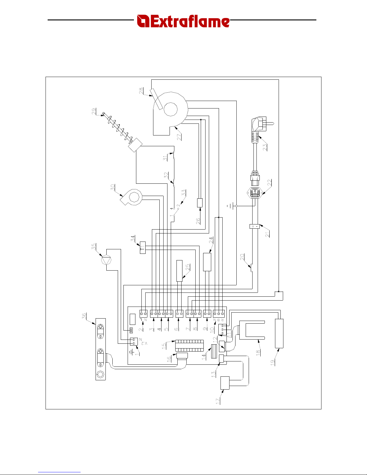
14. WIRING DIAGRAM
Wiring diagram
Page 32
Page
32
Wiring Diagram
Numbering Description
1 Pump power supply terminal
2 Circuit board power supply terminal
3 Flue gas expulsion motor power supply terminal
4 Cross-flow fan power supply terminal
5 Pellet loading geared motor power supply terminal
6 Spark plug power supply terminal
7 Flue gas probe input terminal
8 External thermostat input terminal
9 Room probe input terminal
10 Encoder input terminal
11 Water probe input terminal
12 Depression sensor input terminal
13 Serial port
14 Weekly programmer terminal
15 Microprocessor base
16 Display connector
17 Serial port
18 Depression control circuit board
19 Water probe
20 Remote bulb safety thermostat at 85°C
21 Two-way switch
22 Three-pin mains plug
23 Power supply cable
24 Room thermostat probe
25 Spark plug
26 Flue gas expulsion motor condenser
27 Flue gas expulsion motor
28 Flue gas probe
29 Pellet loading geared motor
30 Cross-flow fan
31 Remote bulb safety thermostat at 100°C
32 Min. pressure switch
33 Max. pressure switch
34 External thermostat (optional)
35 Pump
36 Display
Page 33
Page
33
15. TABLE OF DISPLAY MESSAGES
MESSAGES
Message
Display
Cause Solution
Atte
An attempt has been
made to switch on a stove
again when it has just been shut down (normal
shutdown or caused by an alarm situation).
When the stove has just been shut down (normal
shutdown or caused by an alarm situation), you have
to wait until it is completely cold and then clean the
brazier.
It is possible to re-
start the stove only after having
carried out this operation.
Hot
Room thermostat set at maximum value.
In this operating mode the stove no longer has a
temperature level but is working manually with all 5
power levels. To exit this function, simply lower the
room temperature by pressing button 2.
Lou
Room thermostat set at minimum value.
In this operating mode, the stove works only at the
1st power level no matter what power is set.
To exit this function, simply raise the room
temperature by pressing button 3.
T on
An external thermostat has been connected.
The room thermostat probe is disconnected.
The room thermostat probe is interrupted.
To exclude an external thermostat, just disconnect it.
Any other resetting
operations must be carried
out by an authorised technician.
Stby
The stove is off and on s
tandby to be re-
started.
In this mode, the stove can be switched on/off by
means of a supplementary thermostat (see
“Mechanical thermostat with energy saving”
).
To exclude this function, simply raise the room
temperature by pressing button 3.
Doff
The sto
ve is off due to the
“Day/Night
Temperature Function”
and on standby to be
re-started.
To stop the stove from starting again due to the
“Day/Night Temperature Function”,
press button 1
and hold for three seconds, which switches the stove
off.
To dis
able th
is function completely, press button 4
and hold it down, then press button 5.
Hoff
The temperature of the water has exceeded
the set threshold by 5°C.
Check the correct functioning of the hydraulic system.
When the temperature has lowered (5° under the set
threshold) the machine will re-start automatically.
To exclude the eventual re
-ignition of the stove press
button 1 for 3 seconds taking the stove to off.
Raf / Blac
Out
No power
When the shutdown cycle is completed, the stove
will
light again automatically.
Pul
The automatic cleaning of the
brazier is in
progress.
The automatic cleaning of the
brazier
takes place at
regular intervals of continuous operation.
The automatic cleaning is not carried out when the
stove is in power level 1 position.
Page 34
Page
34
ALARMS
Message
Display D1
Cause Solution
Indicates the presence of an alarm
This indicator lights up when one of the alarms described
below is in progress and is accompanied by the
corresponding indication on display D1. To reset the alarm,
press butto
n 1 and hold for three seconds when the stove
is completely cold.
If the light is flashing, it indicates that the depression
sensor is deactivated.
All resetting operations must be carried out by an
authorised technician
Fum Fail
The flue gas motor is bl
ocked.
The speed control probe is faulty.
No power supply to the flue gas motor.
All resetting operations must be carried out by an
authorised technician
Fumi tc
The flue gas probe is broken.
The flue gas probe is disconnected from
the board.
All resettin
g operations must be carried out by an
authorised technician
High Temp
The cross
-flow fan is faulty.
Excessive pellet feed.
No power supply to the cross-flow fan.
Adjust the flow of pellets (see
“Pellet Load Adjustment”
).
Other resetting operations must b
e carried out by an
authorised technician.
Depr Fail
The flue gas exhaust pipe is obstructed.
The combustion chamber is dirty.
The pressure sensor is faulty.
The ash drawer is not closed properly.
The door is not closed properly.
Check to make sure that t
he exhaust outlet and the
combustion chamber are clean.
Check to see if the drawer is sealed properly.
Check to see if the door is sealed properly.
Other resetting operations must be carried out by an
authorised technician.
No Acc
The pellet tank is empty
.
The spark plug is faulty or out of position.
Inadequate pellet load setting.
Check the level in the pellet tank.
Check the procedures described in “
Ignition”
.
Adjust the flow of pellets (see
“Pellet Load Adjustment”
)
Other resetting operations must be ca
rried out by an
authorised technician.
No Acc
Blac Out
No electricity during the lighting phase.
Press button 1 to switch off
the stove and repeat the
procedure described in “
Ignition
”.
No pell
The pellet tank is empty.
Pellet feeding is insufficient.
Th
e feed motor still has to settle in.
The geared motor is not loading pellets.
Check the level in the pellet tank.
Adjust the flow of pellets (see
“Pellet Load Adjustment”
).
Other resetting operations must be carried out by an
authorised technician.
Hight H2O
The circulation pump is blocked.
Insufficient system pressure.
Presence of air in the system.
Check the pressure of the water system.
Bleed the air from the system.
Other resetting operations must be carried out by an
authorised technician.
Atte + allarme
Attempt to release alarm with stove still
cooling
Every time the stove visualises one of the above-listed
alarms it will automatically switch off.
The stove will block any attempt to release the alarm
during this phase visualising the alarm itself and ATTE
alternately .
Release of the alarm using button 1 is only possible when
the appliance is switched off.
Nr. telefono
- - - - - - - - - -
Display of the service centre
telephone number.
When an alarm occurs, the type of alarm detected
and the telepho
ne number of the service centre flash
on the display in alternation.
If the number has not been entered, the display
shows a series of dashes.
Page 35
Page
35
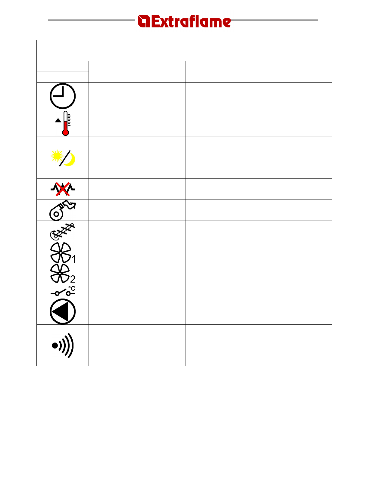
INDICATOR LIGHTS
LED indicator
light
Meaning Description
Weekly Programmer
function
This LED is on/of
f when
Weekly programmer
is on/ off.
For all the settings regarding this function, see the section
Weekly programmer
.
Room Thermostat
function
This LED is on/
off
when the room temperature is lower/higher
than the temperature set.
To modify the temperatu
re setting, use buttons 2 and 3 during
normal operation.
Day/Night Temperature
function
This led is on/off when the
Day/Night Temperature
function is
on/off.
To enable/dis
able the
Day/Night Temperature
function, press
button 4 and hold it down, then pre
ss button 5. For all settings
related to this function, see the section
Day/Night Temperature
Function
.
Spark plug deactivation
This LED is on/off when the spark plug is active/inactive.
To reactivate the spark plug, contact an authorised
technician.
Flue gas motor operation
This LED is on/off when the flue motor is running/not running.
Pellet load motor operation
This LED is on/off when the pellet
load
motor is running/not
running.
During normal operation, this LED lights up intermittently.
Cross-over fan operation
This LED is on/off when the
cross-over fan
is running/not
running.
Not used
Not used
Not used
Not used
Indicates pump functioning
It is switched on/off when the circulation pump is
activated/deactivated.
Communication established between
remote control and stove
Each time you press a button on the remote control, this LED
should light up.
If it stays on, it means that communication between the remote
control and the stove is blocked.
To reset component operation, contact an
authorised
technician.
Page 36

Page
36
16. WARRANTY
EXTRAFLAME S.p.A. reminds you that the manufacturer possesses the rights stated on
Italian Decree no. 24 from the 2nd February, 2002, and that the following warranty
does not jeopardise these rights.
This warranty certificate by Extraflame S.p.A., with headquarters in Montecchio Precalcino (VI), Via
dell’Artigianato, 10 (Italy), extends to all components of the stove supplied by Extraflame S.p.A.,
and includes free repair or replacement of any faulty part of the stove, on condition that:
• The defect is detected within 2 YEARS of the delivery date and is reported to an Extraflame
S.p.A. Technical Assistance Centre no longer than 2 months after its detection;
• It is recognised as a defect by an Extraflame S.p.A. Technical Assistance Centre.
The client will not be charged for any costs or expenses related to interventions carried out by the
Extraflame S.p.A. Technical Assistance Centre if these are covered by the warranty conditions.
WARRANTY CONDITIONS
The warranty is considered valid on condition that:
1. The stove is installed according to all related norms and to the information contained in the
installation, use and maintenance manual, by qualified personnel.
2. The warranty certificate has been filled in and signed by the customer and convalidated by
an Extraflame S.p.A. Technical Assistance Centre or by the vendor.
3. The document which proves the warranty, filled in and accompanied by the receipt, is duly
conserved and shown to Extraflame S.p.A. personnel in the event of an intervention.
The warranty is not considered valid in the following cases:
1. Warranty conditions have not been respected.
2. Installation has not been carried out respecting all related norms or the information in this
manual.
3. Whenever the client is judged to have been negligent due to incorrect or absent
maintenance of the stove.
4. Presence of electrical and hydraulic systems not compliant with the current norms.
5. Damage caused by atmospheric, chemical or electrochemical agents, improper use of the
product, modifications or tampering with the product, unsuitability of the flue/chimney,
and/or any other causes not depending on the manufacture of the product
6. Damage caused by normal corrosion phenomena or deposits typical of heating systems
(condition valid for products using water).
7. Damage caused by the use of non original spare parts or due to service performed by
technical personnel not authorised by Extraflame S.p.A.
8. Improper or negligent use of the stove.
9. Any damage caused by transport. We therefore recommend that you carefully inspect the
goods on receipt, immediately notifying the vendor of any damage and making note of
such on the shipping document and on the shipper’s copy.
Page 37

Page
37
Extraflame S.p.A. is not liable for eventual damage which may be caused, either directly or
indirectly, to people, things and pets as the result of not following the instructions indicated in this
installation, use and maintenance manual or the current norms related to installation and
maintenance of this product.
The warranty excludes:
• The gaskets, all ceramic or tempered glass, cast iron or Ironker facings or grills, painted,
chromium-plated or gold-plated components, majolica, handles and electrical cables.
• Chromatic variations, cracks and slight variation in size of the majolica pieces do not
constitute a reason for contestation, as they are natural characteristics of the materials
themselves.
• Building works.
• Parts for the production of domestic hot water not supplied by Extraflame S.p.A. (only
products using water)
• The heat exchanger is excluded from the warranty unless an anti-condensation circuit is
installed (only products using water)
• The warranty excludes any calibrations or adjustments of the product relating to the type
of fuel or type of installation
Other clauses
Should any faulty or malfunctioning part be detected during normal use, these parts will be
replaced free of charge by the vendor or by our local Technical Assistance Centre.
This clause applies also to other countries, with the exception of particular conditions agreed upon
during the contract-writing phase with the distribution agent abroad.
Replacement of parts does not result in warranty extension.
No compensation will be given for the period in which the product is out of use.
This is the only valid warranty and no one is authorised to supply other warranties either in the
name of or on behalf of EXTRAFLAME S.p.A.
Recommended inspection (extra charge)
Extraflame recommends having an operational inspection of the product by an Extraflame
Authorised Technical Assistance Centre which will supply all the information regarding its correct
use.
SERVICE UNDER WARRANTY
The service request must be forwarded to the vendor.
RESPONSIBILITY
EXTRAFLAME S.p.A. shall not be liable for any direct or indirect damage caused by or
depending on the product.
COMPETENT COURT
For any controversy, the competent court shall be the court of Vicenza, Italy.
Page 38
Page
38
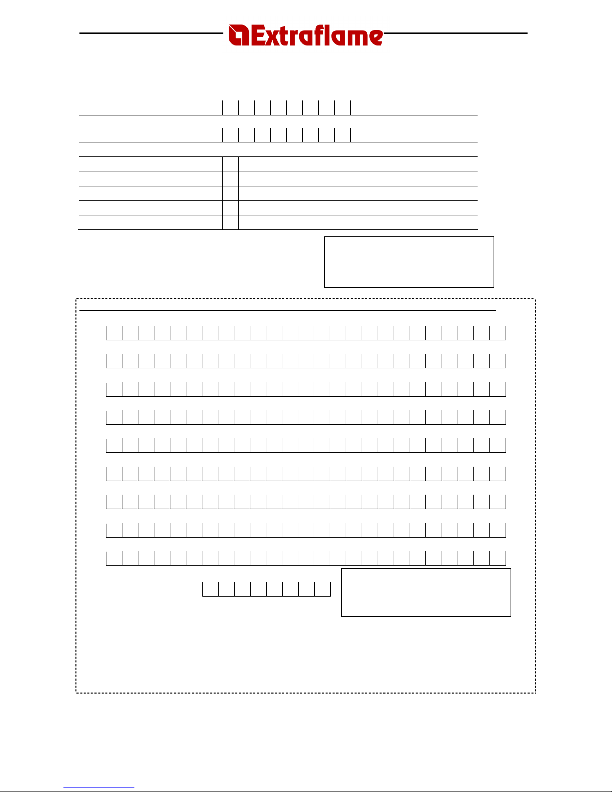
17. QUALITY CONTROL
Model
Serial no.
Tests carried out
- automatic ignition
- combustion air motor
- convection air motor
- appearance
- packing/technical data label
Technician’s signature ________________ Stamp
Date of purchase ___________________
Cut out and send to the manufacturer within 15 days of the date of purchase
Name
Surname
Address
Postcode
City
Telephone
Model
Serial number
Vendor
IMPORTANT: ○ I accept ○ I do not accept
Notice as per Law 196/2003 – Your personal data is treated by our company with full respect for Italian Law 196/2003 for the
entire duration of the contractual relationships established and also thereafter for the fulfilment of all legal obligations as well as to
carry out effective management of the commercial relationships. The data may be communicated to other external subjects only for the
purpose of overseeing credit matters and for the protection of our rights regarding the single commercial relationship, and may also be
communicated to third parties for the fulfilment of specific legal obligations. The interested party has the right to exercise his rights as
per Art.7 of the above-mentioned law.
Date of purchase
Stamp
Stamp
Page 39
Page
39
18. COMPATIBILITY WITH RoHS AND WEEE DIRECTIVES
European Directives
The European Union has approved new Directives with the aim of reducing the potentially
hazardous substances in order to reduce risks to health and the environment, as well as
guaranteeing the safe disposal of electrical and electronic appliances through re-use, recycling and
energetic recovery of the waste.
RoHS Directive
The 2002/95/EC European Directive dated 27.01.2003 (known as the RoHS Directive –
“
Restriction of Hazardous Substances
”), starting from 01.07.2006, limits the use of the
substances successively listed, used in electric and electronic appliances, which are considered
dangerous to human health.
Substances subject to the provisions:
• Lead
• Mercury
• Hexavalent chromium
• Polybrominated biphenyls (PBB)
• Polybrominated diphenyl ether (PBDE)
• Cadmium
WEEE Directive
The 2002/96/EC European Directive dated 27.01.2003 (known as the WEEE “Waste Electrical
and Electronic Equipment” Directive) uses measures and strategies for the disposal of waste
deriving from electric and electronic appliances.
The directive applies the concept of the manufacturer’s extended responsibility: the manufacturers
must pay for collection, storage, transport, recovery, recycling and correct disposal of their
appliances once they have reached the end of the lives.
It is important to note to note that these directives are not applied to products marketed before 1
July 2006. This means that all products available in the warehouse before that date are not subject
to the regulation and can be marketed without consequences.
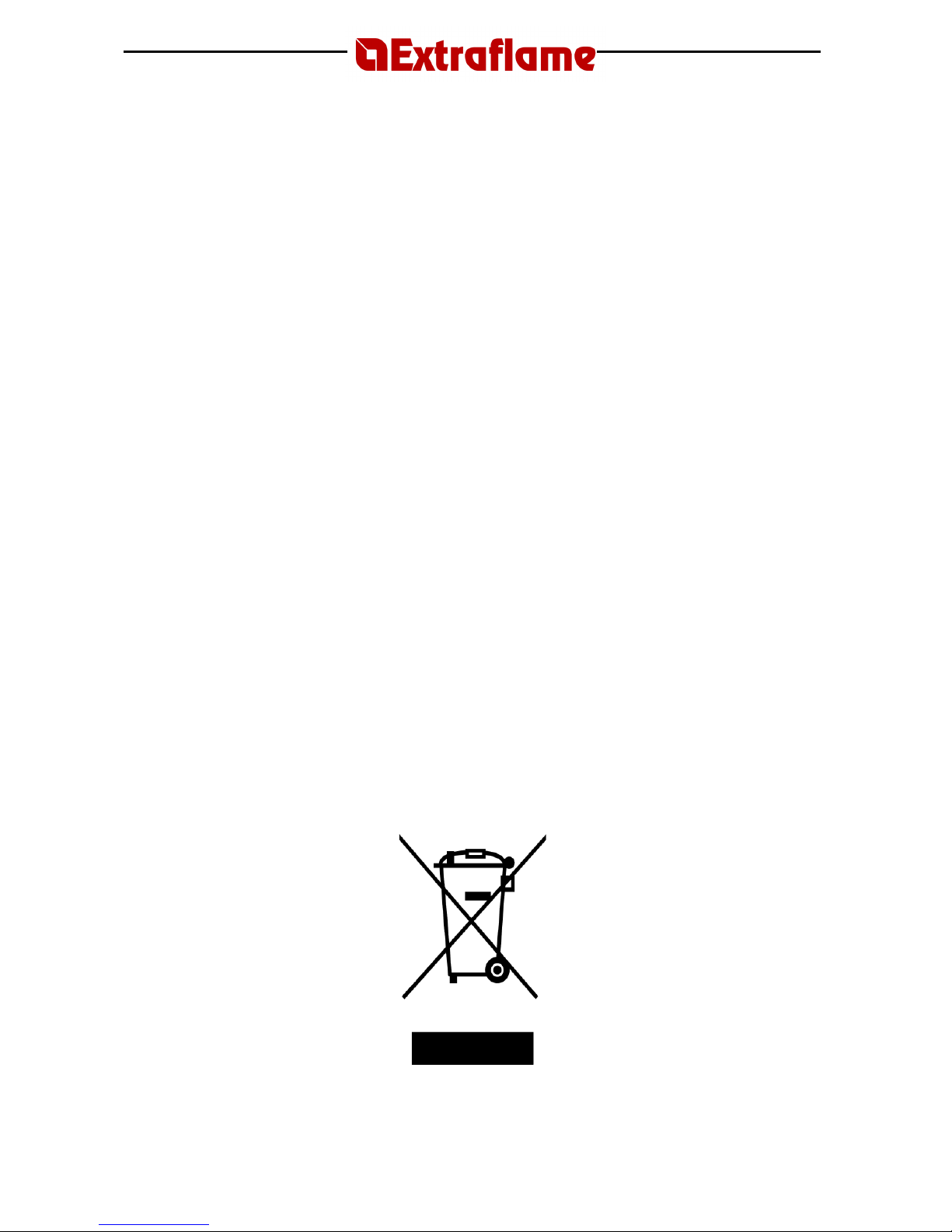
The directive is applied to all products where the symbol shown below appears in the technical
data label.
Page 40
Page
40
PELLET STOVES
EXTRAFLAME S.p.A.
Via Dell’Artigianato, 10
36030 MONTECCHIO PRECALCINO
Vicenza - ITALY
Tel. 0445/865911
Fax 0445/865912
http://www.extraflame.com
E-mail: [email protected]
004275286
REV 006 16.04.2007
Manuale Utente Ecologica Idro
 Loading...