

Extraflame DIADEMA - LILIANA IDRO idro User Manual

1
DIADEMA - LILIANA IDRO IDRO
USER MANUAL
ENGLISH/INGLESE

2

index
ENGLISH
We thank you for having chosen our company; our product is a great heating solution developed from the
most advanced technology with top quality machining and modern design, aimed at making you enjoy
the fantastic sensation that the heat of a ame gives, in complete safety.
enGLiSH ....................................................................................................................................................................................................................................5
WarninGS ..................................................................................................................................................................................5
Safety ........................................................................................................................................................................................ 5
routine Maintenance .......................................................................................................................................................... 5
HydrauLic SySteM .................................................................................................................................................................. 6
InstallatIon and safety devIces................................................................................................................................................................................. 6
safety devIces for closed vessel system ............................................................................................................................................................. 6
dIstances of safety devIces accordIng to the standard ........................................................................................................................ 6
type of SySteM ........................................................................................................................................................................7
closed vessel plant ............................................................................................................................................................................................................ 7
safety valves ............................................................................................................................................................................................................................. 7
closed expansIon vessel ................................................................................................................................................................................................... 8
commIssIonIng checks ....................................................................................................................................................................................................... 8
automatIc thermostatIc mIxer valve (mandatory) ....................................................................................................................................... 8
LiLiana idro - diadeMa idro baSic HydrauLic SySteM diaGraM .............................................................................9
stove posItIonIng ................................................................................................................................................................................................................10
rearMS ..................................................................................................................................................................................... 10
featureS .................................................................................................................................................................................10
deviceS ....................................................................................................................................................................................11
reference StandardS ........................................................................................................................................................11
general .......................................................................................................................................................................................................................................12
inStaLLation .......................................................................................................................................................................... 13
fuMeS exHauSt SySteM.......................................................................................................................................................14
general requIrements .....................................................................................................................................................................................................14
smoke duct ...............................................................................................................................................................................................................................15
chImney .......................................................................................................................................................................................................................................17
chImney caps ...........................................................................................................................................................................................................................17
fumes exhaust system product requIrements ..............................................................................................................................................18
combustIon products outlet quota ....................................................................................................................................................................18
technIcal InstallatIon documentatIon .............................................................................................................................................................19
peLLetS and feedinG ...........................................................................................................................................................20
3

ENGLISH
controL paneL ......................................................................................................................................................................21
dIsplay Icons key ..................................................................................................................................................................................................................21
GeneraL Menu .......................................................................................................................................................................22
basIc InstructIons .............................................................................................................................................................................................................22
tHe reMote controL ...........................................................................................................................................................23
enable delayed swItch-off ...........................................................................................................................................................................................23
type and replacement of batterIes ........................................................................................................................................................................23
coMMiSSioninG SettinGS ...................................................................................................................................................24
adjustIng tIme, day, month and year .....................................................................................................................................................................24
adjustIng the language .................................................................................................................................................................................................24
operation and LoGic ..........................................................................................................................................................25
additionaL rooM tHerMoStat ........................................................................................................................................ 26
addItIonal thermostat functIonIng wIth stby actIve.............................................................................................................................26
addItIonal thermostat functIonIng wIth stby deactIvated...............................................................................................................26
aux ............................................................................................................................................................................................ 26
Menu Structure ................................................................................................................................................................... 27
set power ..................................................................................................................................................................................................................................28
set temperature ....................................................................................................................................................................................................................28
Set adjuStMentS ..................................................................................................................................................................28
burn pot cleanIng ...............................................................................................................................................................................................................28
stand - by ....................................................................................................................................................................................................................................28
enable chrono.......................................................................................................................................................................................................................29
pellet adjustment ..............................................................................................................................................................................................................29
uSer Menu...............................................................................................................................................................................29
set clock ...................................................................................................................................................................................................................................29
chrono ........................................................................................................................................................................................................................................30
adjustIng language ..........................................................................................................................................................................................................31
dIsplay .........................................................................................................................................................................................................................................31
reset ..............................................................................................................................................................................................................................................32
otHer functionS ..................................................................................................................................................................32
aIr dIscharge ..........................................................................................................................................................................................................................32
fIrst load ...................................................................................................................................................................................................................................32
Maintenance ......................................................................................................................................................................... 33
daiLy cLeaninG to be carried out by tHe uSer ...........................................................................................................33
diSpLayS ..................................................................................................................................................................................37
aLarMS ....................................................................................................................................................................................38
4

ENGLISH
WARNINGS
This instructions manual is an integral part of the product: make sure that it always accompanies the appliance, even if
transferred to another owner or user, or if transferred to another place. If it is damaged or lost, request another copy from the
area technician. This product is intended for the use for which it has been expressly designed. The manufacturer is exempt from
any liability, contractual and extracontractual, for injury/damage caused to persons/animals and objects, due to installation,
adjustment and maintenance errors and improper use.
Installation must be performed by qualied sta, which assumes complete responsibility for the denitive installation
and consequent good functioning of the product installed. One must also bear in mind all laws and national, regional,
provincial and town council Standards present in the country in which the appliance has been installed, as well as the
instructions contained in this manual.
The Manufacturer cannot be held responsible for the failure to comply with such precautions.
After removing the packaging, ensure that the content is intact and complete. Otherwise, contact the dealer where the appliance
was purchased.
All electric components that make up the product must be replaced with original spare parts exclusively by an authorised aftersales centre, thus guaranteeing correct functioning.
SAFETY
The generator must not be used by persons (including children) with reduced physical, sensory and mental capacities or
who are unskilled persons, unless they are supervised and trained regarding use of the appliance by a person responsible for
their safety.
Children must be checked to ensure that they do not play with the appliance.
Do not touch the generator when you are barefoot or when parts of the body are wet or damp.
The safety and adjustment devices must not be modied without the authorisation or indications of the manufacturer.
Do not pull, disconnect, twist electric cables leaving the stove, even if disconnected from the electric power supply mains.
It is advised to position the power supply cable so that it does not come into contact with hot parts of the appliance.
The power supply plug must be accessible after installation.
Do not close or reduce the dimensions of the airing vents in the place of installation. The airing vents are essential for
correct combustion.
Do not leave the packaging elements within reach of children or unassisted disabled persons.
The hearth door must always be closed during normal functioning of the product.
When the appliance is functioning and hot to the touch, especially all external surfaces, attention must be paid
Check for the presence of any obstructions before switching the appliance on following a prolonged period of inactivity.
The generator has been designed to function in any climatic condition (even critical). In particularly adverse conditions
(strong wind, freezing) safety systems may intervene that switch the generator o. If this occurs, contact the technical aftersales service and always disable the safety systems.
In the event the ue catches re, use suitable systems for suocating the ames or request help from the re brigade.
This appliance must not be used to burn waste
Do not use any ammable liquids for ignition
During the lling phase do not put the bag of pellets to into contact with the product
The majolicas are top quality artisan products and as such can have micro-dots, crackles and chromatic imperfections.
These features highlight their valuable nature. Due to their dierent dilation coecient, they produce crackling, which
demonstrate their eective authenticity. To clean the majolicas, it is recommended to use a soft, dry cloth. If a detergent or
liquid is used, the latter could penetrate inside the crackles, highlighting them.
ROUTINE MAINTENANCE
Based on Decree 22 January 2008 n°37 art.2, routine maintenance means interventions aimed at reducing degradation due to
normal use, as well as dealing with accidental events entailing the need of rst interventions, which however do not modify
the structure of the system upon which one is intervening or its intended use according to the requirements laid down by the
technical standards in force and by the manufacturer's use and maintenance manual.
5
ENGLISH
HYDRAULIC SYSTEM
Certain concepts referring to the Italian UNI 10412-2 (2009) Standard are described in this chapter.
As previously described, when installing, all national, regional, provincial and town council Standards in force provided by the
country in which the appliance has been installed must be complied with.
During installation of the stove it is MANDATORY to adjust the system with a manometer in order to display the water pressure.
INSTALLATION AND SAFETY DEVICES
The installation, relative system connections, commissioning and inspection of correct functioning must be carried out perfectly,
in total compliance with Standards in force, both national, regional and municipal, as well as these instructions.
For Italy, installation must be carried out by professionally authorised sta (Ministerial Decree dated 22.01.08 n°37).
The manufacturer declines all responsibility for damages to objects and/or persons caused by the system.
SAFETY DEVICES FOR CLOSED VESSEL SYSTEM
According to the UNI 10412-2 (2009) Standard in force in Italy, the closed systems must have: safety valve, pump control
thermostat, acoustic alarm activation thermostat, temperature indicator, pressure indicator, acoustic alarm, regulation automatic
circuit breaker switch, automatic circuit breaker block switch (block thermostat), circulation system, expansion system, safety
dissipation system incorporated with the generator with thermal safety valve (self-activated), whenever the appliance does not
have a temperature self-adjustment system.
DISTANCES OF SAFETY DEVICES ACCORDING TO THE STANDARD
The temperature safety sensors must be in place on the machine at a distance no greater than 30 cm from the ow connection.
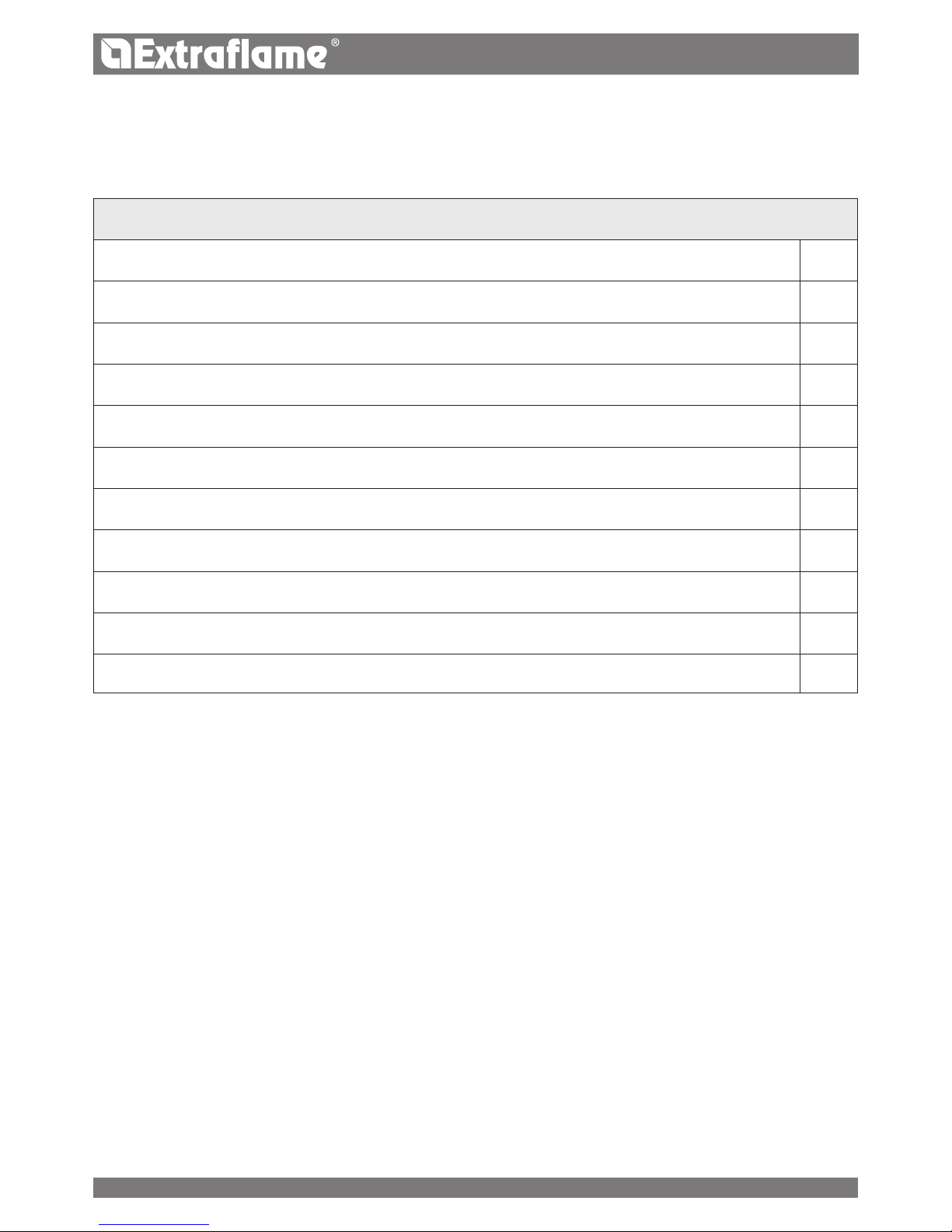
TABLE OF DEVICES FOR CLOSED VESSEL SYSTEM, PRESENT AND NOT PRESENT IN THE PRODUCT
Safety valve
R
Pump control thermostat (managed by the water probe and board program)
R
Acoustic alarm activation thermostat
Water temperature indicator (display)
R
Pressure transducer with display
R
Acoustic alarm
Automatic circuit breater switch (managed by board program)
R
Pressure transducer with minimum and maximum pressure switch alarm
R
Water overheating automatic circuit breaker (blocking thermostat)
R
Circulation system (pump)
R
Expansion system
R
6

ENGLISH
Whenever the generators lack a device, those missing can be installed on the generator ow pipe, within a distance no greater
than 1m from the machine.
COMPONENT DISTANCE
Temperature safety sensors On the machine or not exceeding 30 cm
Missing devices because not as per standard Not exceeding one metre, on the ow pipe
The domestic heating appliances with automatic feeding must: be equipped with a fuel block thermostat or with a cooling
circuit set up by the appliance manufacturer.
The cooling circuit must be activated by a thermal safety valve, in order to ensure that the limit temperature set forth by the
Standard is not exceeded.
Connection between the power supply unit and the valve must be free from interceptions.
The pressure upstream from the cooling circuit must be at least 1.5 bar.
TYPE OF SYSTEM
There are two dierent types of system:
Open vessel plant and closed vessel plant.
The product has been designed and realised to work with closed vessel systems.
CLOSED VESSEL PLANT
System in which the water it contains is not in direct or indirect communication with the atmosphere. Generally, the closed
vessel system has one of the following expansion vessels:
Pre-loaded closed expansion vessel with membrane impermeable to the passage of gases.
Automatic closed expansion system with compressor and membrane impermeable to the passage of gases.
Automatic closed expansion system with transfer pump and membrane impermeable to the passage of gases.
Expansion system without diaphragm.
GENERALITY
The closed systems must have:
Safety valve
Pump control thermostat
Acoustic alarm activation thermostat
Temperature indicator
Pressure indicator
Acoustic alarm
Adjustment automatic circuit breaker switch
Automatic circuit breaker switch (block thermostat)
Circulation system
Expansion system
Safety dissipation system incorporated with the generator with thermal safety valve (self-activated), whenever the
appliance does not have a temperature self-adjustment system
SAFETY VALVES
The load capacity of the safety valve must allow the discharge of a quantity of vapour, not lower than: Q / 0.58 [kg/h] where: Q
is the useful outlet power to the generator water expressed in kilowatt. The diameter of the minimum net transversal section
of the valve inlet must not be lower than 15 mm. The valve load pressure, equal to the calibration pressure, increased by the
overpressure, cannot exceed the maximum exercise pressure of the heat generator. The designer must check that the maximum
pressure existing in every point of the system, does not exceed the maximum exercise pressure of its every component . The
safety valve must be connected to the upper part of the heat generator or outlet pipes, very close to the generator. The length
of the piping between the generator coupling and the safety valve must not exceed 1 m. The piping connecting the safety valve
to the heat generator must not be interrupted and must not have, in any point, a cross-section lower than than that of the safety
7

1
2
3
ENGLISH
valve inlet or than the sum of the inlet cross-sections, in the event of several valves serving a single pipe. The discharge piping
of the safety valve must be realised in order not to prevent the regular functioning of the valves and not to cause damages to
persons; the discharge must ow immediately near the safety valve and be accessible and visible. The diameter of the discharge
piping must not however be lower than that of the outlet connection of the safety valve. For diameter of outlet connection it is
intended the minimum internal diameter on the valve outlet upstream of the eventual internal threading.
CLOSED EXPANSION VESSEL
Warnings: check that the preload of the expansion vessel is set to 1.5 bar.
The vessel maximum exercise pressure must not be lower than the calibration pressure of the safety valve, increased by
overpressures, characteristic of the same valve, bearing in mind the eventual level dierence between vessel and valve and
the pressure generated by the functioning of the pump. The capacity of the expansion vessel/s is evaluated depending on the
total system capacity as results from the project. The closed expansion vessels must comply with the provisions concerning the
design, manufacturing, conformity assessment and use of pressure appliances. Intercepting objects or section decreases must
be inserted/practiced on the connection piping, which can be constituted by system portions. The insertion of a three-way
intercepting valve which allows connection between the vessel and the atmosphere for maintenance Operations, is allowed.
Such device must be protected against accidental manoeuvres. The connection pipe must be realised in order not to present
scales or deposits storage points. In case of more heat generators which feed the same plant or the same secondary circuit, each
heat generator must be connected directly to the expansion vessel or plant expansion vessels unit, altogether dimensioned
for the total volume of water contained in the same plant or the same independent circuit. Where it is necessary to separate
the individual heat generator from the expansion vessel or expansion vessels unit, a three-way tap must be applied on the
connection piping between the generator and the vessel, in order to ensure, in every position, the connection of the generator
with the expansion vessel or with the atmosphere. The expansion vessels, the connecting pipes, the bleed pipes and drain pipes
must be protected from freezing, where this phenomenon occurs. The solution used for this purpose is described in the design.
COMMISSIONING CHECKS
Before connecting the boiler:
a) wash all system piping in order to remove any residues which might compromise the correct functioning of certain system
components (pumps, valves, etc.).
b) check to verify that the ue has adequate draft, is not narrowed and that other appliances do not discharge into the ue.
This is to prevent unexpected power increases. Only after this control can the ue tting be mounted between the boiler and
the ue. A check of the connections with pre-existing ues is recommended.
AUTOMATIC THERMOSTATIC MIXER VALVE MANDATORY
It is required to create an adequate anti-condensation circuit that ensures a return temperature for the appliance of at least 55°
C. The anti-condensation valve, for example, is applied in solid fuel boilers as it prevents the return of cold water in the heat
exchanger.
Routes 1 and 3 are always open and, together with the pump
installed on the return, they guarantee water circulation
inside the biomass boiler exchanger.
A high return temperature allows eciency improvement,
reduces formation of smoke condensation and prolongs the
life span of the generator.
Valves on the market have dierent calibrations. The manufacturer
advises use of model 55°c with 1" hydraulic connections.
Once the valve calibration temperature is reached,
route 2 is opened and the boiler water goes to the system via
the ow.
Valve sold as an accessory (optional)
8

1 2
3
SI
T
M
S
G
VB
VMTA
T2
T1
T3
A
B
ENGLISH
LiLiana idro - diadema idro basic hydrauLic system diagram
Key
a Combustion air inlet Ø 60mm
b Smoke exhaust outlet Ø 120mm
t1 3 bar safety valve 1/2 "
t2 Boiler ow/output 1"
t3 Boiler return/inlet 1"
m Pressure Gauge
t Thermometer
g Filling system
s Safety valve discharge
si System exhaust
Vb Balance valve
Vmta Thermostatic mixer valve 55°C
Vms Domestic hot water mixing valve
it is recommended to consuLt the tempLates manuaL at for further information reLatiVe to the
hydrauLic connections, air intaKe/fLue exhaust and dimension specifications of the product in
question.
9

AUX
STBY
100°C
85°C
0,0 0,5 1,0 1,5 2,0 2,5
0
1
2
3
4
5
6
ENGLISH
stoVe positioning
For correct product functioning, it is recommended to position it so that it is perfectly level, using a spirit level.
The diagram to the side illustrates the behaviour of the pump
used on our thermo-products at the speeds that can be set.
Flow rate (m
3
/h)
Head (m)
features
diadema idro
LiLiana idro
Water content of the thermo-product heat exchanger (l) 21
Volume of expansion vessel integrated in the thermo-product (l) 8
3 bar safety valve integrated in the thermo-product SI
Minimum and maximum pressure switch integrated into the thermo-product SI
Pump integrated into the thermo-product SI
Pump max. head (m) 5
* Envision a possiblE additional Expansion vEssEl dEpEnding on thE systEm watEr contEnt.
rearms
The gures below illustrate the positions of the tank (85°C) and H2O (100°C) rearms. Contact the qualied technician if one of
the rearms should be triggered, so as to verify the cause.
*
10
ENGLISH
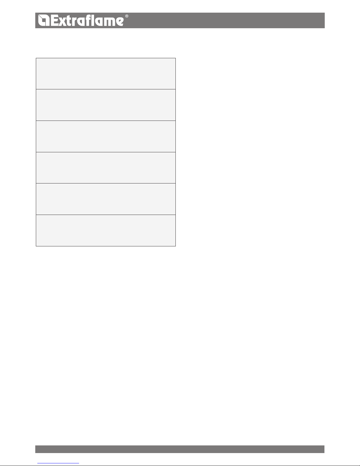
DEVICES
(in the relevant models)
Door micro switch: With the door open, the operation of the
burn pot cleaning system is blocked
Electronic pressure switch: in the event of inadequate pression,
it sends the machine in alarm conditions
F 2.5 A 250 V fuse (stoves): protects the machine from violent
current surges
85°C calibrated mechanical bulb with manual rearm:
intervenes by blocking fuel feed if the pellet tank t° reaches the
limit of 85°C. Rearm must be performed by qualied sta and/
or the manufacturer's technical after-sales assistance.
Pellet tank temperature control probe: if the tank over-heats,
the machine automatically modulates to return to normal
temperature values
Mechanical air pressure switch: blocks the pellet in the event of
insucient depression
REFERENCE STANDARDS
The installation must be in compliance with:
UNI 10683 (2012) heat generators fed with wood and
other solid fuels: installation.
The chimneys must be in compliance with:
UNI EN 13063-1 and UNI EN 13063-2, UNI EN 1457, UNI
EN 1806 in the event of non-metallic chimneys:
EN 13384-1 (13384) chimneys. Thermal and uid dynamic
calculation methods.
UNI EN 1443 (2005) chimneys: general requirements.
UNI EN 1457 (2012) chimneys: clay/ceramic ue liners.
UNI/TS 11278 (2008) Metal - chimneys/ue liners/ue
ducts.
UNI 7129 point 4.3.3 Fire Brigade provisions, local rules
and regulations.
NATIONAL, REGIONAL, PROVINCIAL AND TOWN
COUNCIL REGULATIONS
One must also bear in mind all laws and national, regional,
provincial and town council Standards present in the country
in which the appliance has been installed.
TERMS AND DEFINITIONS
Aeration: Air renewal is required both for the disposal of
the combustion products, and to prevent mixtures with a
hazardous content of non-combusted gases.
Closed hearth appliance: Appliance designed for operation
with closed combustion chamber.
Forced draught appliance: Appliance with ventilation in the
fumes circuit and combustion with fumes ow at a positive
pressure with respect to the environment.
Chimney: Structure consisting in one or several walls
containing one or several outow airways.
The purpose of this predominantly vertical element is to expel
the combustion products at a convenient height from the
ground.
Smoke duct: Component or components that connect the
outlet of the heat generator to the chimney.
Chimney cap: Device that placed on the chimney outlet
allows the dispersion of the combustion products even in
presence of adverse weather conditions.
Condensation: Liquid products which form when the fumes
temperature is lower or equal to the water dew point.
Ducting pipe: Pipe made up of one or several predominantly
vertical elements, specically suitable for collecting and
expelling the fumes, as well as to withstand the relative
components and any condensate over time,
suitable to be installed in a chimney, existing or new technical
compartment, even in new buildings.
Sealed installation: Installation of an appliance with sealed
operation, so that all the air required for combustion is taken
from outside.
Maintenance: Set of procedures required to ensure and
maintain safety and functionality over time and maintain the
eciency of the system within the prescribed parameters.
Chimney system: Chimney installed using a combination
of compatible components, manufactured or specied by a
sole manufacturer whose product liability covers the entire
chimney.
Fumes exhaust system: Flue gas exhaust system,
independent from the appliance made up of a smoke duct,
chimney or individual ue and chimney cap.
Radiation area: Area immediately in front of the hearth in
which the radiant heat caused by combustion is diused.
Reux area: Area beyond the extrados of the roof in which
overpressure or depressions occur, which may aect the
proper discharge of the combustion products.
11

ENGLISH
FUNCTIONAL OPERATIONS DIAGRAM
State of the art installation and proper system operation include a series of activities:
1. Preliminary activities:
Verication of the suitability of the power of the heat generator based on the characteristics of the system
verication of the suitability of the installation site,
verication of the suitability of the fumes exhaust system,
verication of the suitability of the outside air inlets;
2. Installation:
implementation of ventilation and connection to the outer air inlets,
implementation and connection to the fumes exhaust system,
assembly and installation,
electric and hydraulic connections,
installation of insulation,
ignition and operation test,
installation of nishings and coverings;
3. Issue of complementary documentation;
4. Inspection and maintenance.
Other actions may be required in relation to specic requests of the competent authority.
PRELIMINARY ACTIVITIES
GENERAL
Verication of compatibility of the system, of any restrictions required by local administrative regulations, special or conventional
requirements resulting from condominium regulations, constraints, laws or administration deeds must precede any other
assembly or installation operation.
One must especially verify the suitability:
of the installation premises, of the appliances already installed in the installation premises and in the adjacent and
adjoining premises, also powered by dierent fuels, with particular reference to non-compliant installations.
of the fumes exhaust system
of the outside air inlets
SUITABILITY OF THE FUMES EXHAUST SYSTEM
Installation must be preceded by a compatibility test between the appliance and the fumes exhaust system, by verifying:
the existence of documentation relating to the system;
existence and content of the chimney plaque;
suitability of the internal section of the chimney;
absence of obstructions all along the chimney;
predominantly vertical height and development of the chimney;
existence and suitability of the chimney cap;
distance of the outside wall of the chimney and of the smoke duct from
combustible materials;
chimney type and material;
absence of other chimney connections.
12
 Loading...