

Extraflame EcoLogica Idro, ECOLOGICA, I.C. MINI, I.C. MAXI, BABYFIAMMA Use And Maintenance Manual
...
PELLETS STOVES
Use and maintenance manual
BELLADIVINA
ECOLOGICAIDRO
ECO
LOGICA
I.
C. MAXI
BABYFIAMMA PREZIOSA
BELLA LUX CONTESSA
I.
C. MINI
English
2
Congratulations! You are now the owner of an EXTRA FLAME stove !
The pellet stove EXTRA FLAME is an ideal heating solution. It springs from the most advanced
technology and is manufactured to the highest standards with an up-to-date design, allowing you
to enjoy the fantastic sensation which the heat of a flame can give, in complete safety at all
times.
This manual tells you how to use your stove correctly. Please read it all carefully before using.
IMPORTANT
Ensure that the dealer completes the following box with the details of the authorised specialist
who will help you if you have any problems in using your new pellet stove.
AUTHORISED SPECIALIST
COMPANY
MR./MS.
STREET N.
POSTAL CODE TOWN
PHONE FAX
3
Contents
IMPORTANT ................................................................................................................... 2
1 PRECAUTIONS AND SAFETY .......................................................................….... 4
2 TECHNICAL SPECIFICATIONS........................................................…..............…... 5
3 AIR REQUIRED FOR COMBUSTION..............................................….................…. 11
3.1 External air intake pipe assembly.....................................................................….. 11
4 WHAT PELLETS ARE.........................................................................................…. 12
4.1 Pellet storage.......................................................................................…............. 12
5 SAFETY DEVICES.................................................................................................. 13
5.1 Warm air distribution fan breakdown ................................................................... 13
5.2 Fume extractor breakdown ................................................................................... 13
5.3 Pellet loading motor breakdown ........................................................................... 13
5.4 Lighting failure..................................................................................................... 13
5.5 Temporary power failure ...................................................................................... 13
5.6 Electrical safety.................................................................................................... 13
5.7 Fume exhaust safety............................................................................................. 13
5.8 Safety for pellet overheating ................................................................................. 13
5.9 Safety plant pressure ( Ecologica Idro)…………………………….............……..…... 13
5.10 Safety water boiling (Ecologica Idro)……...............…………………....……………. 13
6 ASSEMBLY & INSTALLATION INSTRUCTIONS.........................................…............ 14
6.1 Assembly............................................................................................................. 14
6.2 Installation ....................................................................................…................... 14
6.3 Fume exhaust....................................................................................................... 15
6.4 Electrical connection............................................................................................. 16
6.5 Canalisation DIVINS PLUS………………………………………………...............…….16
7 INSTALLATION I.C. Maxi and Mini ……..………………………………..…...........….17
8 CONTROL PANEL……………………………………………………………..............… 23
8.1 Description of control panel alarms………………………………............….………… 24
9 USE.............................................................................…................…................. 24
10 LIGHTING......................................................................................……............... 25
11 NORMAL OPERATION – TURNING OFF, REMOTE CONTROL.….................…......... 25
11.1 Normal operation ...............................................................................….…......... 25
11.2 DIVINA PLUS operation………………………………………………............………… 26
11.3 Turning off.................................................................................…....................... 26
11.4 Remote control...........................................................................…....................... 26
12 ROOM THERMOSTAT............................................................................................ 27
12.1 Digital thermostat........................................................................................…...... 27
12.2 Mechanical thermostat (optional)........................................................................... 28
12.2.1 Mechanical thermostat installation (optional).......................................................... 28
12.2.2 Mechanical thermostat operation .......................................................................... 28
12.2.3 Mechanical thermostat operation with energy saving function (Stby)........................ 28
12.2.4 Mechanical thermostat operation for canalis.motor (DIVINA PLUS)……................... 28
12.3 User parameters…………………………………………………………..............……. 30
13 CHRONOTHERMOSTAT……………....................................................................... 31
13.1 “Day/Night” temperature function..................................................................…… 32
13.2 Pellet feeding adjustment…………......................................................................... 32
13.3 Motor parameters for DIVINA PLUS connection ………............…………………..…. 33
13.4 Alarm signalling.................................................................................….......…… 34
14 Operation of the radiofrequency remote control for I.C. Mini…………..............…. 35
15 CLEANING AND MAINTENANCE.....................................................................…. 41
15.1 Cleaning Ecologica,I.C.Maxi, Ecologica IDRO.........................................................42
15.2 Cleaning Bella, Bella Lux, Divina, Contessa,Preziosa, Babyfiamma ……..............…. 44
15.3 Cleaning I.C.Mini................................................................................................. 46
15.4 Chimney connection...........................................................................…............... 46
16 PROBLEMS, CAUSES AND SOLUTIONS................................................................. 47
17 GUARANTEE................................................................……................................. 49
18 QUALITY CONTROL...............................................................……....................... 50
19 APPENDIX…………………………………………………………….…………........…. 51
4
1 PRECAUTIONS AND SAFETY
The stoves manufactured in our works are built
with the maximum dedication to the individual
components so as to protect both the user and
the installer from accidents. The qualified
personnel are therefore advised to pay special
attention to the electrical connections after
every operation on the product, especially with
regard to the stripped part of the wires which
must not protrude in any way from the terminal
block, thereby preventing possible contact with
the live parts of the wire.
Installation must be carried out by qualified
personnel who must issue a declaration of
compliance of the system with good practice
to the purchaser, who shall assume responsibility for the definitive installation and consequent proper operation of the product
installed. Extraflame S.p.A. shall not be
responsible in the event of failure to
observe these precautions.
This instruction manual constitutes an integral
part of the product: ensure that it always
accompanies the appliance, even if passed to
another owner or user or moved to another
installation. If damaged or lost, ask the local
technical service for another copy.
This stove must be used exclusively for the
applications it was expressly designed for.
The manufacturer shall not be responsible
contractually or extra-contractually for any
damage caused to persons, animals or property
by installation, adjustment and maintenance
errors, or by improper use.
After removing the packaging, ensure that the
contents are intact and complete. If this is not
the case, contact the dealer from whom the
appliance was purchased.
Stove maintenance must be carried out at least
once a year, scheduling it sufficiently in
advance with the service centre.
The following safety precautions must be
observed:
The use of the stove by unattended children and
handicapped persons it not recommended.
Do not touch the stove if you are bare-footed or
if parts of your body are wet or damp.
Modifying the safety or adjustment devices
without the manufacturer’s approval or
instructions is forbidden.
Never pull, detach or twist the electric wires
coming out of the boiler even when the electricity
supply is disconnected.
Do not plug or reduce the dimensions of the
aeration apertures of the room in which the
stove is installed.
The aeration openings are indispensable for a
correct combustion.
Never leave the packaging materials within
reach of children or unattended disabled
persons.
ONLY FOR THE MODEL IDRO:
Before installation, we recommend that you
thoroughly wash all the piping in the system to
remove any residues which could affect the
efficiency of the appliance.
During installation, it is necessary to inform
users that:
• If there is any water leakage, they must shut
off the water supply and promptly notify the
technical support service.
• They must periodically check the working
pressure of the plumbing system.
If the stove is not being used for a long period,
users are advised to call the technical
assistance service engineers to carry out at
least the following operations:
• Turn the main switch to position 0
• Close the water cocks of both the heating
and sanitary systems
• Drain the heating and sanitary systems if
there is any risk of freezing
Stove maintenance must be carried out at least
once every year, scheduling it sufficiently in
advance with the service centre.
5
2 TECHNICAL SPECIFICATIONS
All a.m. data are not binding, but valid just as an indication.
The right to make technical modifications for improving the product is reserved.
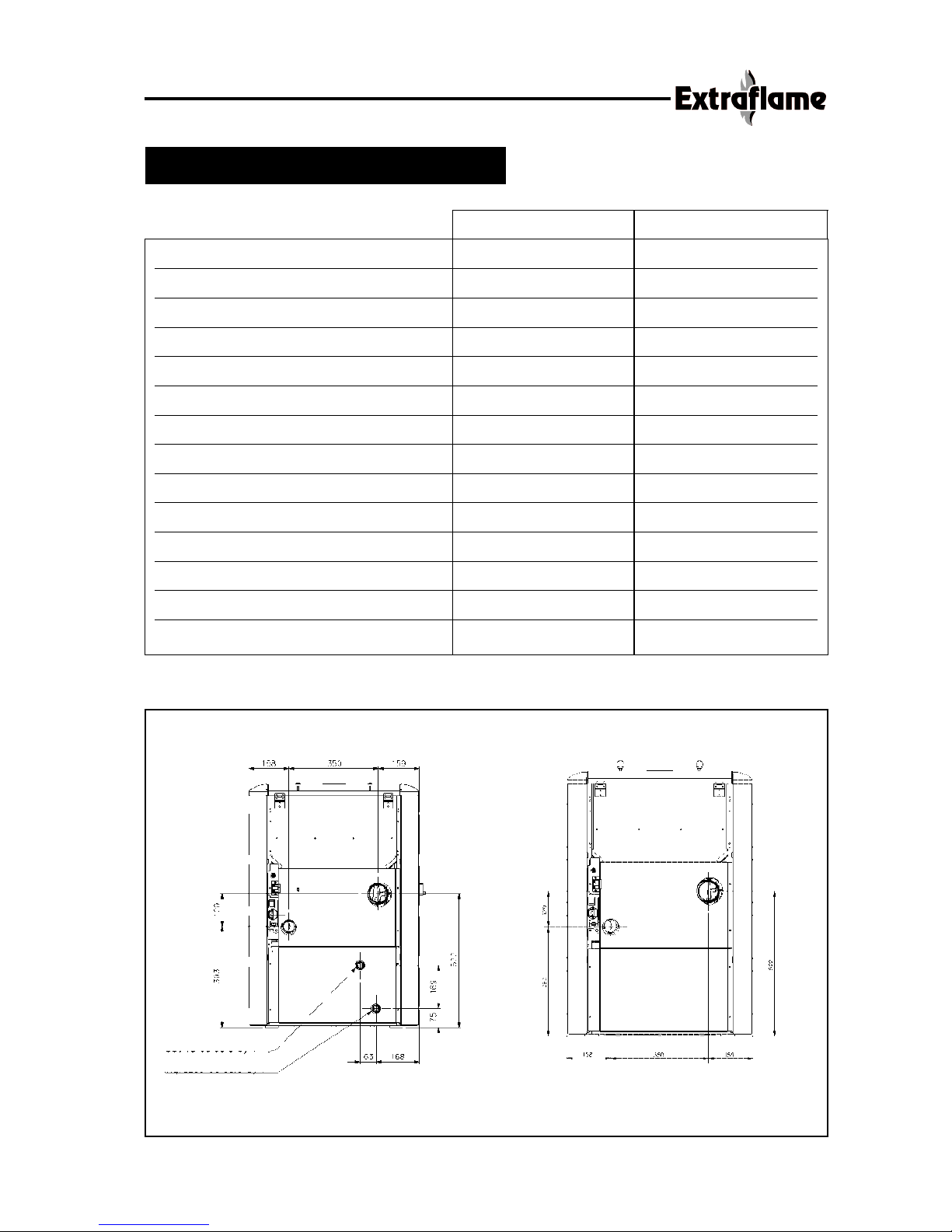
Height 945 mm. 945 mm.
Width 670 mm. 670 mm.
Depth 670 mm. 670 mm.
Weight 156 Kg. 150 Kg.
Fume exhaust pipe diameter 80 mm. 80 mm.
Max heating volume / m
3
220 m
3
Total power 14,47 kW/h 2,5 - 11 kW/h
Water power 8,5 kW/h / kW/h
Pellet consumption per hour 0,6 - 3,0 Kg/h 0,6 - 2,4 Kg/h
Absorbed electrical power 25 - 190 W 25 - 100 W
Lighting power +280 W +280 W
Power supply 230 V 50 Hz 230 V 50 Hz
Feed box capacity ~30 kg. ~35 kg.
Inlet/outlet water pipe “ 3/4 “ /
EcoLogica Idro
Ecologica
EcoLogica
EcoLogica Idro
B
A
B
A
A: FUMES OUTLET PIPE ø 80
B: AIR INTAKE PIPE ø 50
Boiler outlet “3/4
Boiler inlet “3/4
6
TECHNICAL SPECIFICATIONS
All a.m. data are not binding, but valid just as an indication.
The right to make technical modifications for improving the product is reserved.
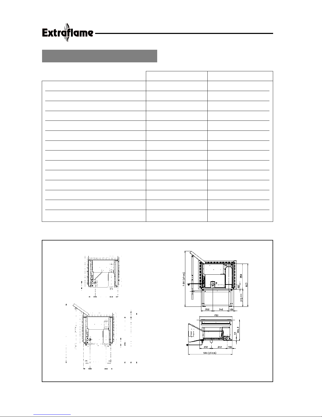
Height 606 mm. 550 mm.
Width 640 mm. 700 mm.
Depth 717 mm. 450 mm.
Weight 130 Kg. 110 Kg.
Fume exhaust pipe diameter 80 mm. 80 mm.
Max heating volume 190 m
3
150 m
3
Total power 2,5 - 9,4 kW/h 2,5 - 7,5 kW/h
Water power / kW/h / kW/h
Pellet consumption per hour 0,6 - 2,0 Kg/h 0,6 - 1,6 Kg/h
Absorbed electrical power 25 - 100 W 25 - 100 W
Lighting power +280 W +280 W
Power supply 230 V 50 Hz 230 V 50 Hz
Feed box capacity ~ 28 kg. ~ 12 kg.
Inlet/outlet water pipe “ / “ /
I.C. Maxi
I.C. Mini
I.C. Mini
WITH PELLET FEEDING KIT
355
141
143
97
143 355 141
1310 (circa)
1109
1029
80
97
606
423***
I.C. Maxi
*** Minimum Height
The detail “ adjustment pipe”
is pre-drilled with 3 holes Ø 8,5 : 90-100.
For other adjustments, drill according to needs.
A: FUMES OUTLET PIPE Ø80
B: AIR INTAKE PIPE Ø 50

7
*** Minimum Height
The detail “ adjustment pipe”
is pre-drilled with 3 holes Ø 9 :
90-100-90.
For other adjustments, drill
according to needs.
A: FUMES OUTLET PIPE ø 80
B: AIR INTAKE PIPE ø 50
A
B
I.C. Maxi

8
TECHNICAL SPECIFICATIONS
All a.m. data are not binding, but valid just as an indication.
the right to make technical modifications for improving the product is reserved.
Height 858 mm. 884 mm.
Width 440 mm. 477 mm.
Depth 470 mm. 446 mm.
Weight 100 Kg. 110 Kg.
Fume exhaust pipe diameter 80 mm. 80 mm.
Max heating volume 100 m
3
100 m
3
Total power 1,7 - 5,1 kW/h 1,7 - 5,1 kW/h
Water power / kW/h / kW/h
Pellet consumption per hour 0,4 - 1,2 Kg/h 0,4 - 1,2 Kg/h
Absorbed electrical power 25 - 100 W 25 - 100 W
Lighting power +280 W +280 W
Power supply 230 V 50 Hz 230 V 50 Hz
Feed box capacity ~ 11 kg. ~ 11 kg.
Inlet/outlet water pipe “ / “ /
BabyFiamma
Preziosa
Preziosa
BabyFiamma
WALL DRILLING
SKETCH
AIR INTAKE PIPE
FUMES OUTLET PIPE
FUMES OUTLET PIPE ø 80
FUMES OUTLET PIPE ø 50
9
TECHNICAL SPECIFICATIONS
All a.m. data are not binding, but valid just as an indication.
the right to make technical modifications for improving the product is reserved.
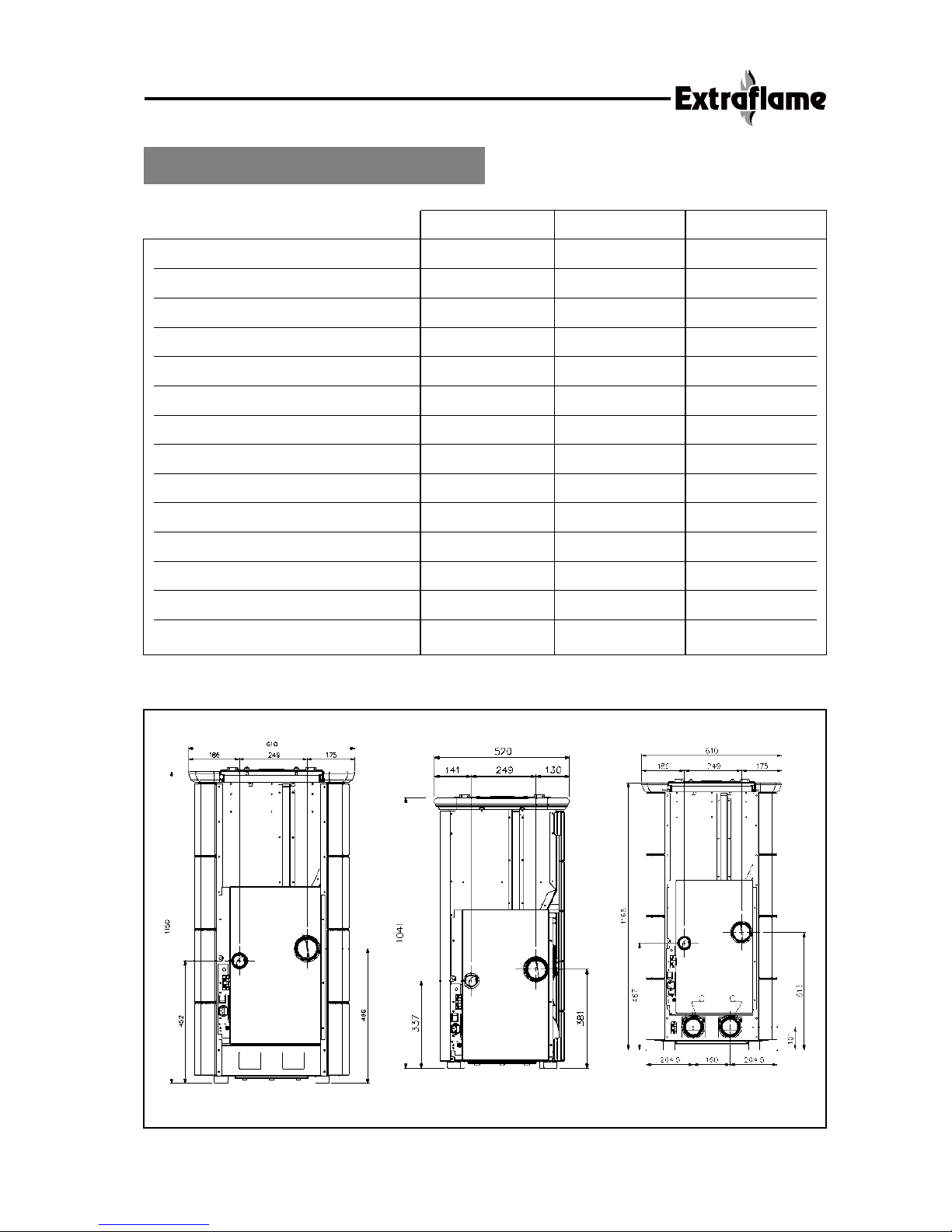
Height 1150 mm. 1041 mm. 1150 mm.
Width 610 mm. 520 mm. 610 mm.
Depth 576 mm. 513 mm. 576 mm.
Weight 170 Kg. 130 Kg. 170 Kg.
Fume exhaust pipe diameter 80 mm. 80 mm. 80 mm.
Max heating volume 220 m
3
150 m
3
220 m
3
Total power 2,5 - 11 kW/h 2,5 - 7,5 kW/h 2,5 - 11 kW/h
Water power / kW/h / kW/h / kW/h
Pellet consumption per hour 0,6 - 2,4 Kg/h 0,6 - 1,6 Kg/h 0,6 - 2,4 Kg/h
Absorbed electrical power 25 - 100 W 25 - 100 W 75 - 210 W
Lighting power +280 W +280 W +280 W
Power supply 230 V 50 Hz 230 V 50 Hz 230 V 50 Hz
Feed box capacity ~ 30 kg. ~ 25 kg. ~ 30 kg.
Inlet/outlet water pipe “ / “ / “ /
Divina
Bella Divina Plus
Divina
Bella
Divina Plus
A: FUMES OUTLET PIPE ø 80
B: AIR INTAKE PIPE ø 50
A
B
A
B
A
B
A: FUMES OUTLET PIPE ø 80
B: AIR INTAKE PIPE ø 50
A: FUMES OUTLET PIPE ø 80
B: AIR INTAKE PIPE ø 50
C: CANALISATION PIPE ø 80
10
TECHNICAL SPECIFICATIONS
All a.m. data are not binding, but valid just as an indication.
the right to make technical modifications for improving the product is reserved.
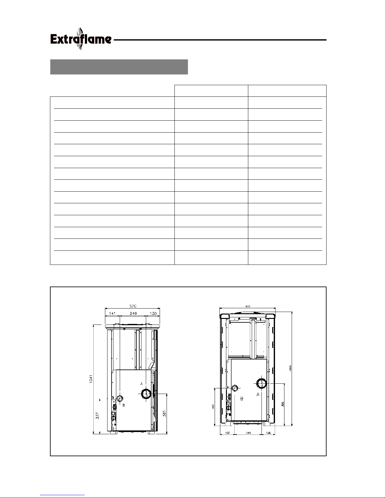
Height 1041 mm. 1068 mm.
Width 520 mm. 522 mm.
Depth 513 mm. 500 mm.
Weight 130 Kg. 150 Kg.
Fume exhaust pipe diameter 80 mm. 80 mm.
Max heating volume 150 m
3
180 m
3
Total power 2,5 - 7,5 kW/h 2,5 - 9,4 kW/h
Water power / kW/h / kW/h
Pellet consumption per hour 0,6 - 1,6 Kg/h 0,6 - 2,0 Kg/h
Absorbed electrical power 25 - 100 W 25 - 100 W
Lighting power +280 W +280 W
Power supply 230 V 50 Hz 230 V 50 Hz
Feed box capacity ~ 25 kg. ~ 25 kg.
Inlet/outlet water pipe “ / “ /
Bella Lux
Contessa
Bella Lux
Contessa
A: FUMES OUTLET PIPE Ø80
B: AIR INTAKE PIPE Ø 50
A: FUMES OUTLET PIPE Ø80
B: AIR INTAKE PIPE Ø 50
11
Combustion always requires air (oxygen). Stoves therefore remove air from the room they are
installed in and this must be replaced.
Bad combustion can be caused by poor air circulation in the house and this is often the case
in modern homes, which have sealed windows and doors. On the other hand, there are also
problems when there are draughts in the room (caused for example by kitchen or bathroom
ventilators). To prevent this type of problem, we suggest
a permanent ventilation grill to be
fitted in a window or near the stove. Alternatively, the air can be taken directly from the
exterior or from another sufficiently aerated room (a cellar, for example) by means of a steel
pipe with a diameter of 48 mm.
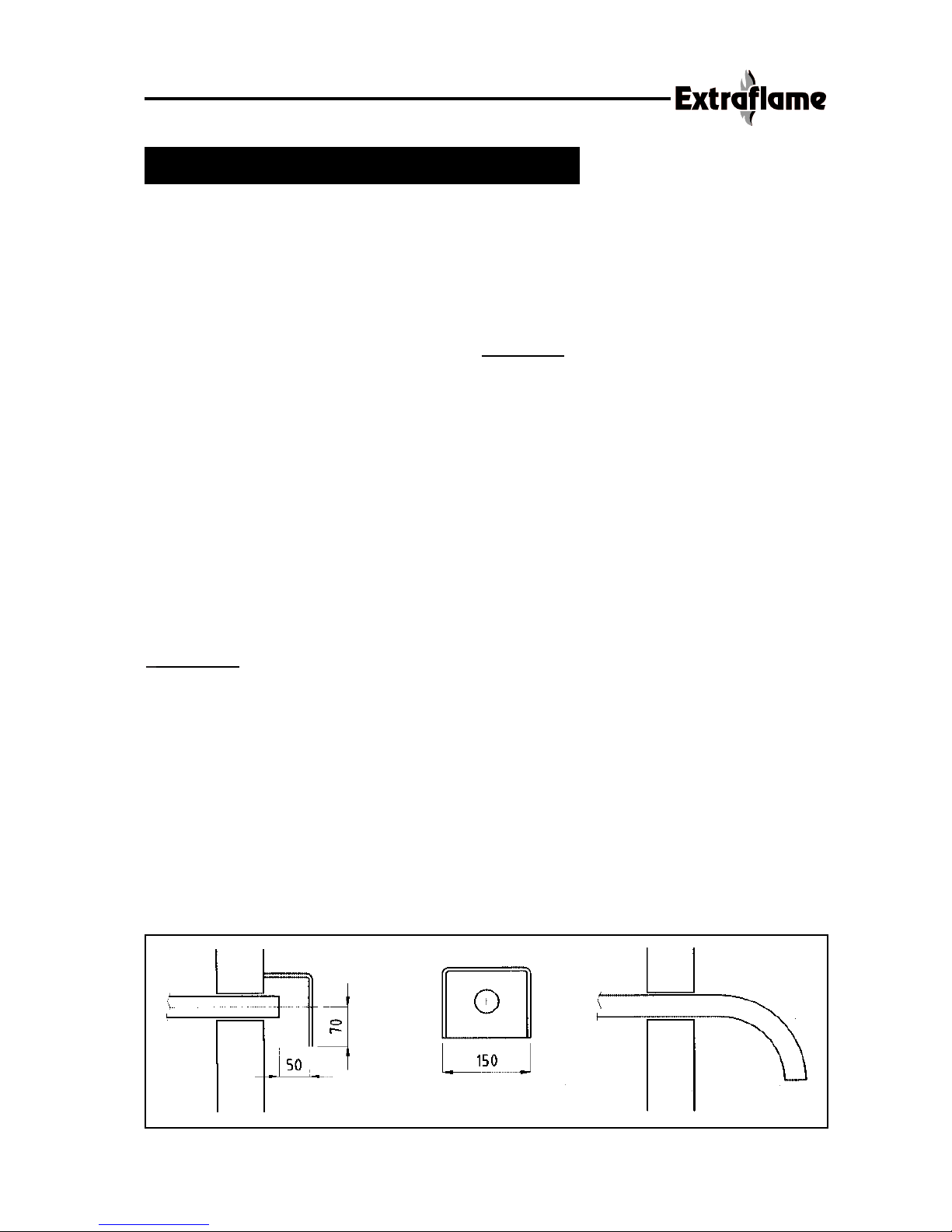
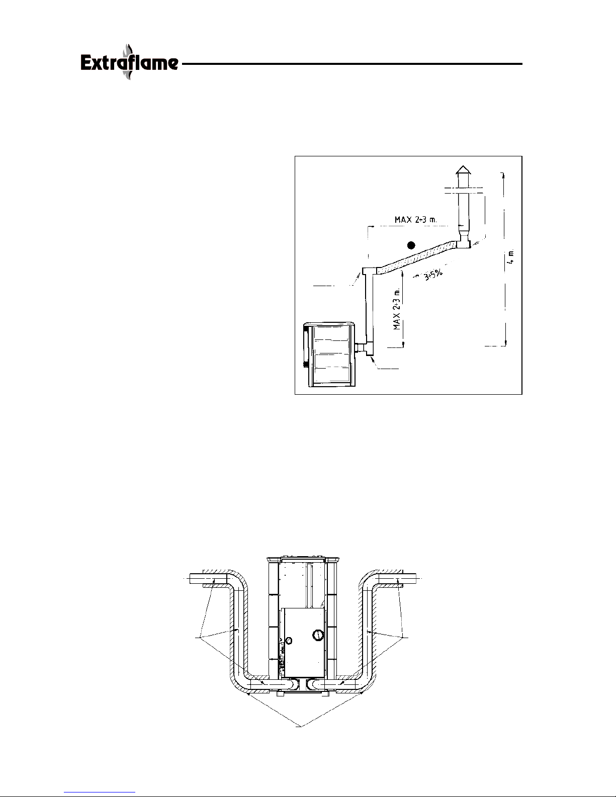
3.1 External air intake pipe assembly
a) Measure and make a hole with a minimum diameter of 5 cm. in the wall for the intake
pipe (see drawing here below).
b) Connect the stove with the exterior by means of a steel pipe.
ATTENTION!
• Only use steel pipes.
• Pipes in synthetic materials or aluminium must not be used.
•To ensure sufficient air intake, the pipe must not be longer than 2 m. and must not have
too many bends.
• If the pipe leads outdoors, it must end with a 90º downward bend and be protected
against the wind (see Fig. Here below).
3 AIR REQUIRED FOR COMBUSTION
11

12
The pellets are made by applying very high
pressure to sawdust, that is pure timber waste
(without paint), produced by sawmills, carpentry
works and other activities associated with the
working and transformation of timber.
This type of fuel is completely environmentally
friendly as no binders of any kind are used to
keep it compact. In fact, the compactness of the
pellets over time is guaranteed by a natural
substance found in the wood itself: the lignite.
As well as being environmentally friendly, as the
wood residues are exploited to the maximum,
pellets also have technical advantages.
While wood has a calorific power of 4.4
kW/kg. (with 15% humidity, after about 18
months seasoning) the power of pellets is 5.3
kW/kg. The density of the pellet is 650 Kg/m3
and the water content is 8% of its weight.
For this reason, the pellets do not need to be
seasoned to obtain an adequate caloric yield.
Their diameter ranges from a minimum of 5
mm to a maximum of 8 mm.
4.1 Pellet storage
To guarantee problem-free combustion, the
pellet must be stored in a dry place.
WARNING
THE USE OF POOR QUALITY PELLETS OR OF
ANY OTHER MATERIAL DAMAGES THE
FUNCTIONS OF YOUR STOVE AND MAY
LEAD TO THE INVALIDATION OF THE WARRANTY
AND ASSOCIATED RESPONSIBILITIES
OF THE MANUFACTURER.
4 WHAT ARE PELLETS ?
13
5.1 Warm air distribution fan breakdown:
If the fan stops for any reason, the stove stops automatically to prevent overheating.
5.2 Fume extractor breakdown:
If the extractor stops, the electronic unit immediately blocks the supply of pellets.
5.3 Pellet feeding motor breakdown:
If the motor stops, the stove continues to operate until the minimum cooling level is reached.
5.4 Lighting failure:
If no flame develops during the lighting stage, the stove automatically makes another attempt to
light and if no flame comes this time either, the stove will show on the display
“ NO ACC”.
While attempting to light the stove , on the display you will read “ATTE” which means “WAIT”.
This function remembers that before lighting the stove , you must be sure that the burning pot,
must be completely free and clean.
5.5 Temporary power failure:
The appliance will re-light automatically after a brief power failure. There may be a minimum
quantity of smoke inside the house when there is no power for a period of 3 to 5 minutes.
THIS DOES NOT GIVE RISE TO ANY SAFETY RISK.
5.6 Electrical safety:
The stove is protected against violent power swings by a master fuse on the rear of the stove
(delayed 2A 250V).
5.7 Fume exhaust safety
An electronic pressure switch stops the loading screw in case the exhaust pipe is obstructed, or
in case the door remains opened for some minutes.
5.8 Safety for pellets overheating
In case of overheating inside the pellet hopper, this safety device stops the functioning of the stove,
the resetting is manual and must be done by a qualified technician.
ONLY FOR ECOLOGICA IDRO:
5.9 Plant pressure safety
A mechanical pressure sensor stops automatically eventually overpressure of the plant. The resetting
of this safety is manual and must be done by a qualified technician.
5.10 Safety for water boiling
In case of water shortage or a minimum water quantity, this safety stops the pellet feeding.
The resetting is manual and must be done by a qualified technician.
5 SAFETY DEVICES
14
6.1 Assembly
An authorised dealer should assemble the
stove.
The assembling of the ceramics in the stoves
which have majolica tiles, must be done by a
qualified technician.
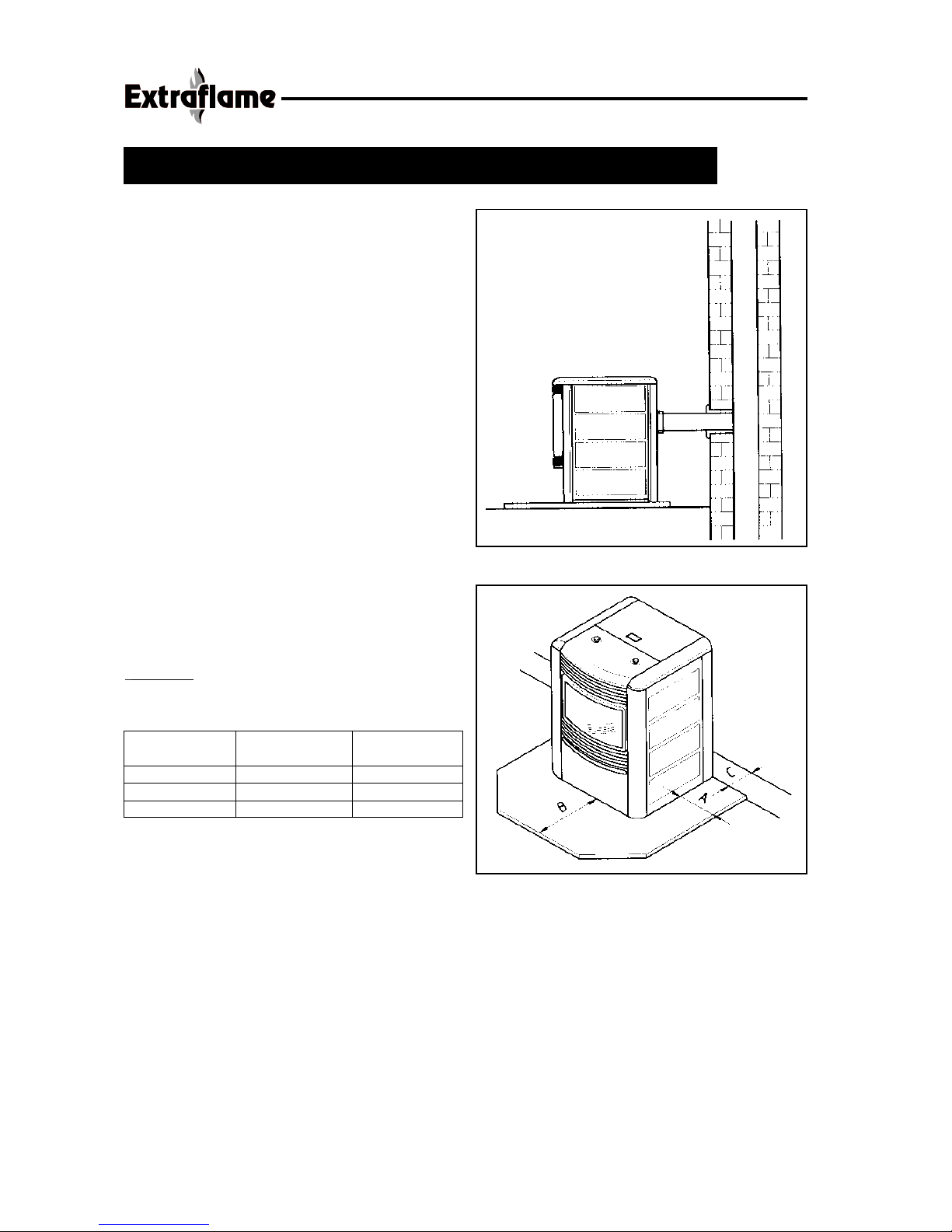
6.2 Installation
a) Paying attention to the dimes of perforation
and taking into consideration a floor pro-
tection plate, if fitted, measure and make
the hole in the chimney for connecting the
fume exhaust pipe with diam. 80 mm.
If the hole has to be done on a wood wall,
the minimum hole diam. must be 130 mm.,
and a min. 20 mm. thickness insulation
material.
b) Connect the stove to the chimney by means
of a steel pipe, sealing it hermetically and
taking care not to obstruct the free section
with the fume pipe. (See fig. 1)
TABLE A: Dimensions of the floor protection
plate and relative safety distances in mm.
6 ASSEMBLY AND INSTALLATION INSTRUCTIONS
REFERENCES
Flammable Not-flammable
objects objects
a* 200 100
b* 800 400
c* 200 100
PRECAUTIONS
1. The appliance must be placed on a flame
resistant floor.
If it is placed on a flammable floor, a floor protection plate must be used. (See table A)
2. The appliance must be connected to a chimney authorised for solid fuels with a minimum
diameter of 130 mm.
3. The fume exhaust system is based on the depression (draught) in the place of combustion
and a light fume exhaust over-pressure (forced exhaust). This makes it essential for the
exhaust pipe to be installed correctly and hermetically.
4. To seal and insulate the pipes, only use heat-resistant materials (up to 300 °C) such as
adhesive tape in aluminium, rock wool or high-temperature silicone.
5. The stove must be placed, so that the electric cord is easy to reach.
fig. 1
fig. 2
*see fig. 4
15
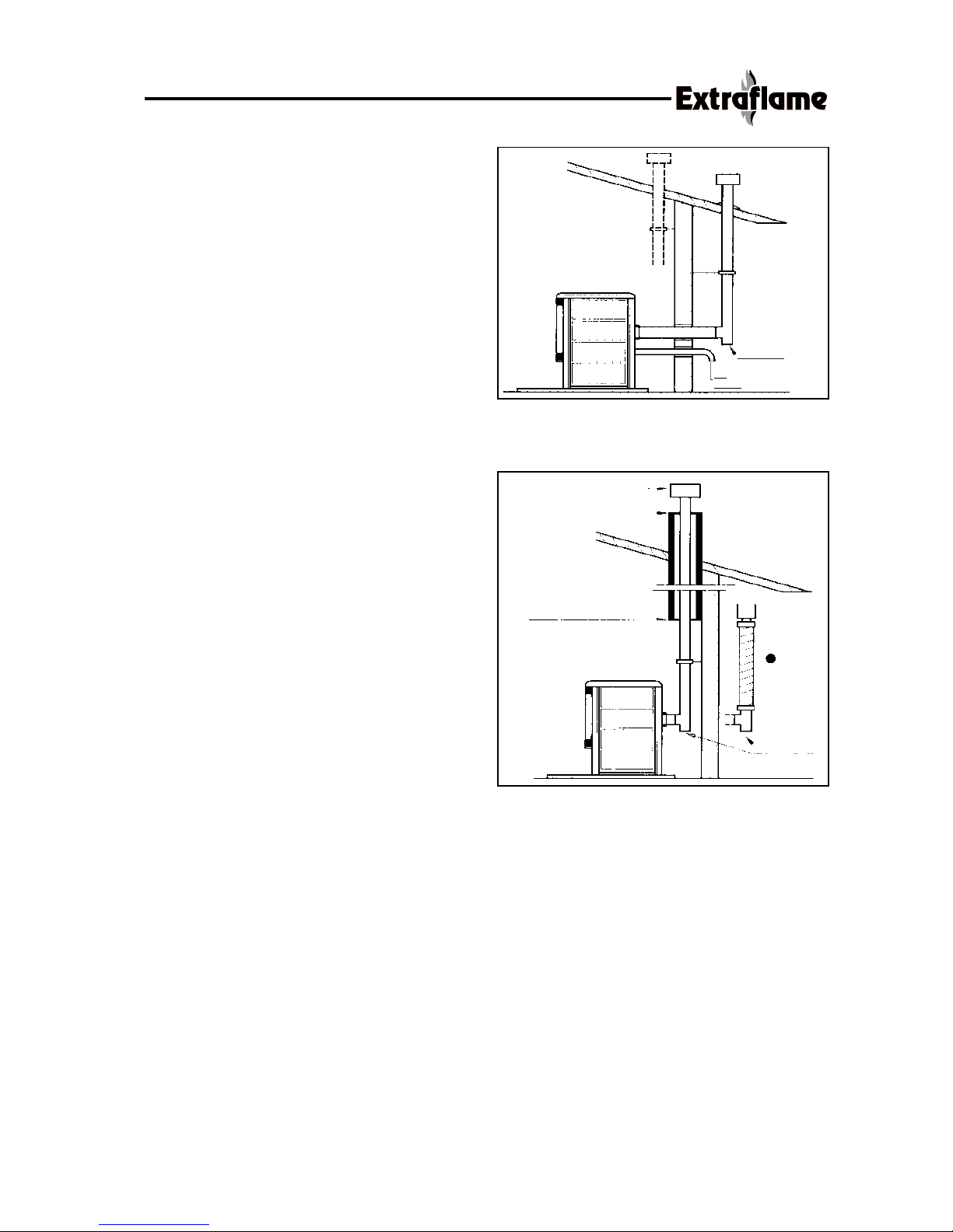
6.3 Fume exhaust
In conformity with DPR 412 and UNI
7129-2001, the allowed installations are:
WITH VERTICAL EXTERNAL OR INTERNAL
FLUE
• The Fig. 3 represents the best solution for
discharging the fumes above the roof.
Proceed as in previous chapter with the
installation of a T-fitting with an inspection
plug. The external or internal flue must
be properly fixed and provided with a
chimney pot for protection from rain.
FUME DISCHARGE THROUGH A CHIMNEY
• Fig. 4 is the classic masonry chimney
system, of course in addition to Fig.1).
Use a T-pipe with an inspection plug and
suitable supporting staffs.
If the chimney is too big, we recommend
reducing it by inserting a porcelain steel
pipe or stainless steel (inox), with a
maximum diameter of 150 mm, and
appropriately sealing the fume inlet and
outlet parts of the fume exhaust from the
part in masonry.
fig. 4
fig. 3
INTERIOR
EXTERIOR
Inspection
Air
intake
Protection from rain
Cover
plate
Airtight sealed
steel plate
Inspection
16
If the fume flue is installed in a fixed way , inspections should be provided for internal
cleaning purposes (ashes), especially in the horizontal sections.
NOTE:
ALL SECTIONS OF THE FUME FLUE MUST
BE EASY TO INSPECT AND TO REMOVE
TO ALLOW THE INTERNAL CLEANING.
( SEE
•)
(SEE FIG. 4 AND 5)
6.4 Electrical connections
The stove is supplied with a power cable
which must be connected to a 230 V /50
Hz socket.
The power absorption is indicated in
chapter 2 (technical specifications).
Make sure that the cable does not come
into contact with the hot surfaces of the
stove.
6.5 CANALISATION DIVINA PLUS
The model DIVINA PLUS is equipped with 2 pipes situated on the back of the stove which
allow the canalisation of the heat issued by the stove. As you can see in the photo here below,
we suggest to make the canalisation by using pipes with the following characteristics:
• Internal diameter 80 mm
• Insulated pipes, that is thermal insulation
• The pipe connection to each nozzle , must not be longer than 2 mt.
fig. 5
Inspection
Inspection
Slope
Height over
Inspection
MAX PIPE LENGTH
2 MT
MAX PIPE LENGTH
2 MT
INSULATING
MATERIAL
 Loading...