

Extraflame Comfort, Comfort P80, Comfort Mini Crystal, Inserto comfort mini, inserto comfort p80 Mini User Manual

Read these instructions carefully before installation, use and maintenance.
The instruction booklet is an integral part of the product.
User Manual
Comfort
Mini
Comfort
Mini Crystal
Comfort
P80

2

3
Congratulations! You are now the owner of an Extra ame stove!
The Extra ame pellet stove is an ideal heating solution. It utilises the most advanced technology and is
manufactured to the highest standards with a contemporary design, allowing you to enjoy the ambience
and warmth of a natural ame in complete safety.
This manual tells you how to use your stove correctly. Please read the entire manual carefully before using
your stove.
IMPORTANT
Make sure that the dealer completes the following box with the details of the authorised specialist who
will help you if you have any problems in using your new pellet stove.
AUTHORISED SPECIALIST
COMPANY __________________________________________________________________
Full name __________________________________________________________________
Address ______________________________________________ No. __________________
Postal Code ____________ City __________________ County. ______________________
TEL. ________________________________ FAX __________________________________
All Extra ame products are manufactured according to the following directives:
89/106 CEE (Construction Products)
89/366 CEE (EMC Directive)
2004/108 CE (EMC Directive)
2006/95 CE (Low Voltage Directive)
And the following standards:
EN 14785
EN 60335-1
EN 60335-2-102
EN 61000-3-2
EN 61000-3-3
EN 50366
EN 55014-1
EN 55014-2

4

5
Index
WARNINGS AND SAFETY DEVICES.......................................................................................................... 7
Chapter 2
WHAT ARE PELLETS?................................................................................................................................. 8
PELLET STORAGE .....................................................................................................................................................................8
PELLET LOADING .....................................................................................................................................................................8
Chapter 3
SAFETY DEVICES ....................................................................................................................................... 9
BREAKDOWN OF HOT AIR DISTRIBUTION FAN............................................................................................................9
FLUE GAS EXTRACTOR BREAKDOWN ..............................................................................................................................9
PELLET LOAD MOTOR BREAKDOWN ...............................................................................................................................9
FAILED IGNITION ......................................................................................................................................................................9
TEMPORARY POWER CUT ....................................................................................................................................................9
ELECTRICAL SAFETY DEVICE ..............................................................................................................................................9
FLUE GAS EXHAUST SAFETY DEVICE ..............................................................................................................................9
PELLET TEMPERATURE SAFETY DEVICE ........................................................................................................................9
Chapter 4
ASSEMBLY AND INSTALLATION INSTRUCTIONS ................................................................................. 10
GLOSSARY ............................................................................................................................................................................... 10
INSTALLATION ........................................................................................................................................................................ 11
ADMISSIBLE INSTALLATIONS .................................................................................................................................... 11
PROHIBITED INSTALLATIONS ....................................................................................................................................11
CONNECTION TO THE EXHAUST VENTING SYSTEM ...............................................................................................12
EXHAUST CHANNEL OR PIPE ....................................................................................................................................12
CHIMNEY OR SINGLE FLUE ........................................................................................................................................13
CONNECTION TO THE FLUE AND COMBUSTION PRODUCT EXHAUST VENTING ................................ 15
CHIMNEY CAP ................................................................................................................................................................. 15
CONNECTION TO EXTERNAL AIR INTAKES ................................................................................................................. 16
INSULATION, TRIMS, FACINGS, AND SAFETY PRECAUTIONS .............................................................................. 16
NATIONAL, REGIONAL, PROVINCIAL AND MUNICIPAL LAWS ............................................................................ 16
Chapter 5
COMFORT MINI/P80/MINI CRYSTAL INSTALLATION ...........................................................................17
FITTING WITH SLIDING BASE ........................................................................................................................................... 17
INSTALLATION WITH PEDESTAL OPTIONAL ............................................................................................................ 18
INSTALLATION WITH PEDESTAL ...................................................................................................................................... 18
EXTRACTING THE INSERT ..................................................................................................................................................19
FITTING THE FRAMES .......................................................................................................................................................... 19
AIR CIRCULATION DUCTS .................................................................................................................................................. 20
Chapter 6
REMOTE CONTROL OPERATION ............................................................................................................23
GENERAL DESCRIPTION .....................................................................................................................................................23
GENERAL FEATURES ............................................................................................................................................................ 24
KEYPAD ..................................................................................................................................................................................... 24
DISPLAY .................................................................................................................................................................................... 24
Chapter 7
PRODUCT FUNCTIONALITY ...................................................................................................................26
BASIC INSTRUCTIONS ......................................................................................................................................................... 26

6
IGNITION .................................................................................................................................................................................. 26
NORMAL OPERATION .........................................................................................................................................................27
SHUTDOWN ............................................................................................................................................................................ 27
Chapter 8
USER MENUS ...........................................................................................................................................28
SET TEMPERATURE MENU .................................................................................................................................................29
SET CLOCK MENU ................................................................................................................................................................. 29
SET TIMER MENU .................................................................................................................................................................. 29
DAY/NIGHT MENU ................................................................................................................................................................31
PELLET LOAD MENU ............................................................................................................................................................ 32
LANGUAGE MENU ................................................................................................................................................................ 33
Chapter 9
ROOM THERMOSTAT ..............................................................................................................................34
MECHANICAL THERMOSTAT OPTIONAL .................................................................................................................. 34
INSTALLING A MECHANICAL THERMOSTAT OPTIONAL..................................................................................... 34
MECHANICAL THERMOSTAT OPERATION ................................................................................................................... 34
MECHANICAL THERMOSTAT OPERATION IN STANDBY MODE TO BE USED ALSO FOR REMOTE
ACTUATOR ............................................................................................................................................................................. 34
Chapter 10
CLEANING ................................................................................................................................................36
CLEANING THE BRAZIER ....................................................................................................................................................36
USE OF SCRAPERS ................................................................................................................................................................ 36
CLEANING OF ASH COLLECTION COMPARTMENTS ............................................................................................... 36
CLEANING THE HEAT EXCHANGER MONTHLY ....................................................................................................... 36
DOOR, ASH DRAWER AND BRAZIER SEALS ................................................................................................................ 37
CHIMNEY CONNECTION .................................................................................................................................................... 37
BRAZIER PARTITION .............................................................................................................................................................38
Chapter 11
TABLE OF DISPLAY MESSAGES ..............................................................................................................39
Chapter 12
WARRAN TY ..............................................................................................................................................42

WARNINGS AND SAFETY DEVICES
7
Chapter1
The stoves produced by our establishment are built with
attention to the individual components in a way to protect
both the user and the installer from any accidents. It is
therefore recommended that after any intervention on the
product, authorised sta pay particular attention to the
electric connections, especially the stripped parts of the
wires. These must not escape from the terminal board in any
situation, thus preventing possible contact with the live parts
of the wire.
Installation must be carried out by authorised sta , who
must provide the buyer with a declaration of conformity
for the system and will assume full responsibility for nal
installation and as a consequence the correct functioning
of the installed product. It is necessary to bear in mind all
laws and national, regional, provincial and town council
Standards present in the country the appliance has been
installed.
Extra ame S.p.A. cannot be held responsible for the
failure to comply with such precautions.
The instruction manual is an integral part of the product:
make sure that it always accompanies the appliance, even
if transferred to other owners or user or is transferred to
another place. If it is damaged or lost, request another copy
from the area technician.
This stove must be destined for the use for which it has been
expressly realised. The manufacturer is exempt from any
liability, contractual and extracontractual, for injury/damage
caused to persons/animals and objects, due to installation,
adjustment and maintenance errors and improper use.
After the packaging has been removed, check the integrity
and completeness of the contents. If this does not comply,
contact the dealer where the appliance was purchased.
All electric components that make up the stove must be
replaced with original spare parts exclusively by an authorised
after-sales centre, thus guaranteeing correct functioning.
The stove must be serviced at least once a year,
programming it in advance with the technical after-sales
service.
Nota bene: In case of thermo product or boiler, the
product or system venting is not covered by the
warranty.
For safety reasons, remember that:
The stove must not be used by children or unassisted
disabled persons.
Do not touch the stove when you are barefoot or when
parts of the body are wet or humid.
The safety and adjustment devices must not be
modi ed without the authorisation or indications of the
manufacturer.
Do not pull, disconnect, twist electric cables leaving the
stove, even if disconnected from the electric power supply
mains.
Do not close or reduce the dimensions of
the airing vents in the place of installation.
The airing vents are indispensable for correct combustion.
Do not leave the packaging elements within reach of
children or unassisted disabled persons.
The hearth door must always be closed during normal
functioning of the product.
Avoid direct contact with parts of the appliance that
tend to heat up during functioning.
Check for the presence of any obstructions before
switching the appliance on following a prolonged standstill
period.
The stove has been designed to function in
any climatic condition (also critical). In particularly
adverse conditions (strong wind, freezing) safety
systems may intervene that switch the stove o .
If this occurs, contact the technical after-sales service and
always disable the safety system.
If the ue should catch re, be equipped with suitable
systems for su ocating the ames or request help from the
re service.
MAJOLICAS
The company have chosen majolica tiles, which are the
result of high-quality artisan work and therefore the
majolica may present crackles, speckles, and shadings.
These characteristics certify their precious origin.
Enamel and majolica, due to their di erent coe cient
of dilatation, produce microcrackles, which show their
authentic feature.
For the cleaning of the majolica we suggest you use a soft
and dry cloth; if you use a detergent or liquid, the latter
might soak in and make the crackles more visible.
WARNINGS AND SAFETY DEVICES
8
WHAT ARE PELLETS?
Chapter2
WHAT ARE PELLETS?
Pellets are made by applying very high pressure to sawdust; i.e. the residue of raw timber (without paint)
produced by sawmills, carpentry works and other activities involved in processing wood.
This type of fuel is completely environmentally friendly, as no binders of any kind are used to keep it
compact. In fact, the compactness of the pellets over time is guaranteed by lignite, a natural substance
found in the wood itself.
As well as being an environmentally friendly fuel, since wood residues are exploited to the maximum,
pellets also have technical advantages.
The density of the pellet is 650kg/m3 and the water content is 8% of its weight. For this reason, pellets do
not need to be seasoned to obtain a su cient heating yield.
The pellet used must conform to the characteristics of the following regulations:
Ö-Norm M 7135
DIN plus 51731
UNI CEN/TS 14961
Extra ame recommends always using 6 mm pellets for its products.
PELLET STORAGE
To guarantee problem-free combustion, the pellet must be stored in a dry place.
PELLET LOADING
Pellets can either be loaded from the front, by removing the insert, or from the side, by using the chute, if
equipped with the support and loading kit.
WARNING!!!
THE USE OF POOR QUALITY PELLETS OR ANY OTHER MATERIAL MAY DAMAGE THE YOUR
STOVE AND MAY LEAD TO THE INVALIDATION OF THE WARRANTY AND THE RELATED
RESPONSIBILITIES OF THE MANUFACTURER.

9
SAFETY DEVICES
Chapter3
SAFETY DEVICES
BREAKDOWN OF HOT AIR DISTRIBUTION FAN
If the blower stops for any reason, the stove automatically shuts down to prevent overheating.
FLUE GAS EXTRACTOR BREAKDOWN
If the extractor stops, the electronic unit immediately prevents pellet loading.
PELLET LOAD MOTOR BREAKDOWN
If the motor stops, the stove continues to operate until the minimum cooling level is reached.
FAILED IGNITION
If no ame develops during the ignition phase, the appliance automatically attempts a new ignition, this
time, though, without loading pellets.
If, after this attempt, the stove still has no ame, the stove display shows “NO FLAME”. If you attempt to
light the stove again, the display shows “CLEANING WAIT” which means “WAIT”.
This function reminds you that before lighting the stove, you must be sure that the brazier is free of
dirt and debris.
TEMPORARY POWER CUT
The appliance will re-light automatically after a brief power failure. When the power goes o , the stove
may emit a minute quantity of smoke inside the house for a period of 3 to 5 minutes.
THIS DOES NOT POSE ANY SAFETY RISK.
ELECTRICAL SAFETY DEVICE
The stove is protected against violent changes in power by a master fuse on the rear of the stove (2A 250V
delayed).
FLUE GAS EXHAUST SAFETY DEVICE
If the exhaust system fails, an electronic pressure switch stops the stove and an alarm is signalled.
PELLET TEMPERATURE SAFETY DEVICE
In case of overheating inside the pellet tank, this safety device blocks stove operation; resetting is manual
and must be performed by an authorised technician.

10
Chapter5
ASSEMBLY AND INSTALLATION INSTRUCTIONS
Chapter5
ASSEMBLY AND INSTALLATION INSTRUCTIONS
The installation must comply with:
UNI 10683 (2005) heat generators fed with wood and other solid fuels: installation.
The chimneys must comply with:
UNI 9731 (1990) chimneys: classi cation according to thermal resistance.
EN 13384-1 (2006) calculation method of the thermal and uid-dynamic features of the chimney.
UNI 7129 point 4.3.3 provisions, local rules and prescriptions of the re brigade.
UNI 1443 (2005) chimneys: general requirements.
UNI 1457 (2004) chimneys: internal ducts in terracotta and ceramics.
GLOSSARY
CLOSED HEARTH DEVICE
Heat generator that can only be opened to load fuel during use.
BIOMASS
Material of organic origin, excluding the material incorporated in geological formations and fossilised.
BIOFUEL
Fuel produced directly or indirectly from biomass.
FLUE or CHIMNEY
Vertical duct for collecting and expelling combustion products from a single appliance at a suitable height
from the oor.
EXHAUST CHANNEL OR PIPE
Duct or connecting element between the heat generating device and the chimney for extracting the
combustion products.
INSULATION
The series of measures taken and materials used to prevent heat transmission through a wall dividing
rooms at di erent temperatures.
CHIMNEY CAP
Device located at the top of the chimney that facilitates dispersion of the combustion products in the
atmosphere.
CONDENSATE
Liquid products that form when the temperature of the combustion gas is lower than or equal to the dew
point of the water.
HEAT GENERATOR
Device that permits the production of thermal energy (heat) by the rapid transformation of the chemical
energy of the fuel by means of combustion.
AIR LOCK
Mechanism for modifying the dynamic resistance of the combustion gasses.

11
ASSEMBLY AND INSTALLATION INSTRUCTIONS
Chapter5
EXHAUST VENTING SYSTEM
A system for fume exhaust venting that is independent from the appliance, composed of a pipe or channel,
chimney or single ue, and chimney cap.
FORCED DRAUGHT
Air circulation by means of a fan driven by an electric motor.
NATURAL DRAUGHT
Draught resulting in a chimney/ ue due to the di erence in the volume mass existing between the (hot)
fumes and the surrounding atmospheric air, without any mechanical suction aid installed inside or on top
of it.
RADIANCE AREA
Area immediately adjacent to the hearth in which the heat produced by combustion is di used; this area
must not contain any objects made of combustible material.
REFLUX AREA
Area in which the combustion products come out from the appliance towards the room in which it is
installed.
INSTALLATION
Before carrying out installation, it is necessary to check the positioning of the chimneys, ues or exhaust
terminal ducts of the appliance, keeping in mind the following:
Installation prohibitions
Legal clearances
Limitations set forth by local administrative regulations or speci c regulations of the authorities.
Common limitations deriving from building regulations, and easement or contract regulations.
ADMISSIBLE INSTALLATIONS
In the room in which the heat generator is to be installed, any existing or installed appliances must be airtight
to the room and must not cause depression in the room with respect to the external environment.
Appliances used for cooking foods and the related hoods without extractor can only be installed in rooms
used as kitchens.
PROHIBITED INSTALLATIONS
The room in which the heat generator is to be installed must not contain any of the following devices,
either pre-existing or installed:
Hoods with or without extractor;
Ventilation ducts of the collective type.
Should these devices be located in adjacent rooms communicating with the installation room, it is
forbidden to use the heat generator simultaneously where there is the risk that one of the two rooms may
be subject to depression with respect to the other.
45°
<
45°
<
12
Chapter5
ASSEMBLY AND INSTALLATION INSTRUCTIONS
CONNECTION TO THE EXHAUST VENTING SYSTEM
EXHAUST CHANNEL OR PIPE
For the assembly of the exhaust channels it is imperative to use non- ammable materials that are resistant to
combustion products and any condensates.
It is forbidden to use exible metal pipes and asbestos cement for connecting the stove to the ue, also for preexisting exhaust channels.
There must be continuity between the exhaust channel and the ue so that the ue does not lean on the stove.
The exhaust channels must not pass through rooms in which the installation of combustion devices is
forbidden.
The assembly of the exhaust channels must be carried out in such a way as to ensure that they are airtight for
the operating conditions of the appliance, as well as to limit the formation of condensates and prevent them
from being conveyed towards the appliance.
The assembly of horizontal sections must be avoided where possible.
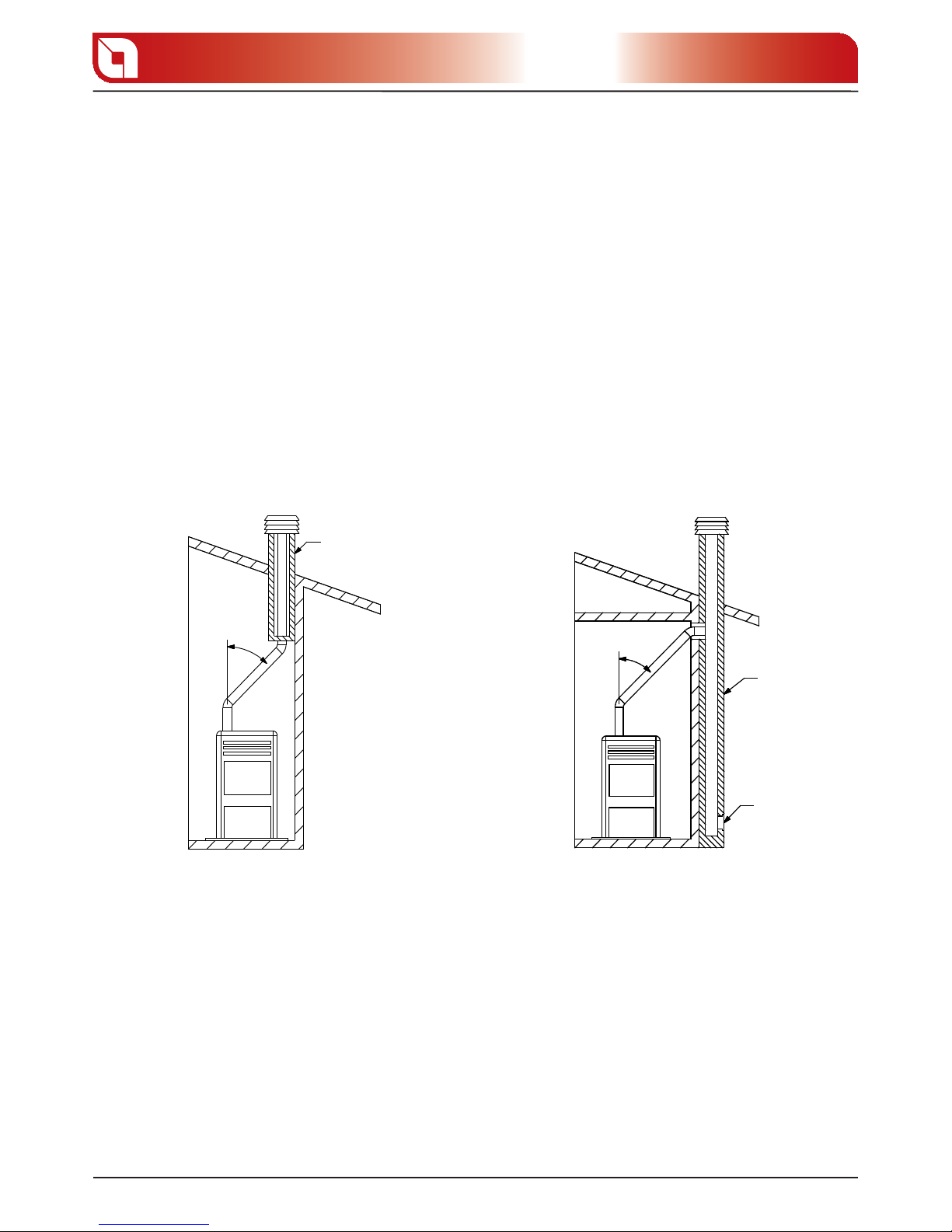
Where roof or wall exhaust outlets have to be reached that are not coaxial in relation to the exhaust outlet
from the appliance, the direction changes must be made using open elbows no greater than 45° (see gures
below).
Insulation
Flue
Inspection
For heat generating devices equipped with an electric exhaust fan, i.e. all products made by Extra ame, it
is necessary to observe the following instructions:
Horizontal sections must have a minimum slope of 3% upwards.
The length of the horizontal section must be as short as possible, and in any case no greater than 3
meters.
No more than four direction changes may be used, including the one resulting from the use of the “T”-
element. (When four bends are used, use double wall piping with a 120 mm diameter.)
In any case, exhaust channels must be sealed in relation to combustion products and condensates, as well
as insulated, if they pass outside the installation room.
It is forbidden to use elements in counter-slope.
The exhaust channel must allow soot recovery and cleaning using a swab.
The exhaust channel must have a constant cross-section. Any changes in cross-section are allowed only at
gure 5.1 gure 5.2
B
C
20 cm
A
13
ASSEMBLY AND INSTALLATION INSTRUCTIONS
Chapter5
the ue connection.
It is forbidden to run other air feed channels or piping for utilities inside the exhaust channels, even if
they are oversized. It is also forbidden to t manual draught adjustment devices on the forced draught
appliance.
CHIMNEY OR SINGLE FLUE
The chimney or ue must meet the following requirements:
be airtight to combustion products, waterproof and properly insulated according to the usage conditions;
be made of materials suitable to resist normal mechanical stress, as well as heat and the action of combustion
products and any condensates;
have a predominantly vertical layout with deviations from the axis no greater than 45°;
be situated at a proper distance from combustible or ammable materials by means of an air gap or suitable
insulation material;
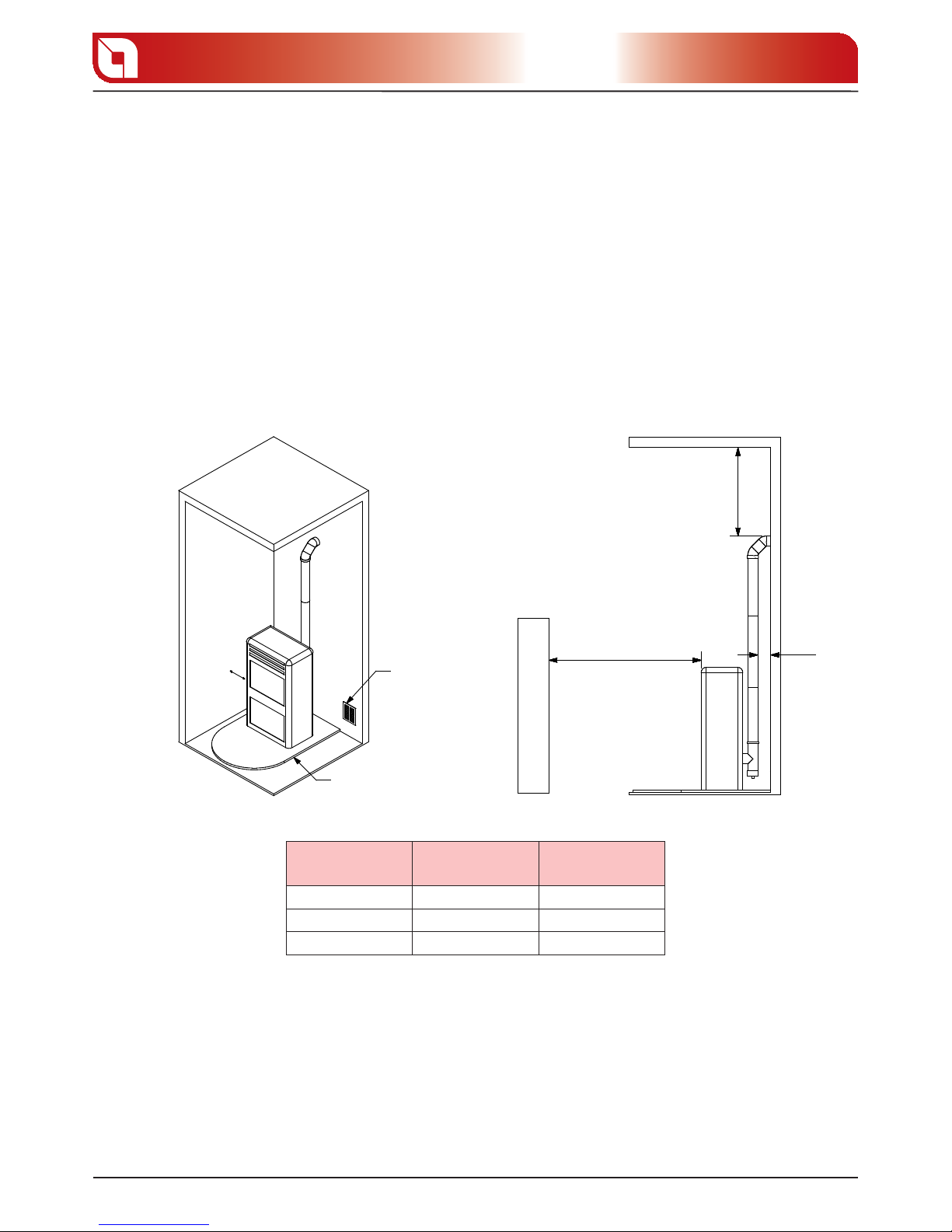
Minimum80 cm
2
Floor protection
REFERENCES
Flammable
objects
Non- ammable
objects
A 200 100
B 1500 750
C 200 100
preferably have a round internal section: square or rectangular sections must have rounded edges
with radius no less than 20 mm;
have a constant, free and independent internal section;
have rectangular sections with a maximum ratio between sides of 1.5.
The exhaust duct should be equipped with a chamber for the collection of solid materials and any
condensates located below the mouth of the exhaust channel, so that it is easy to open and inspect from
the airtight hatch.
gure 5.3 gure 5.4
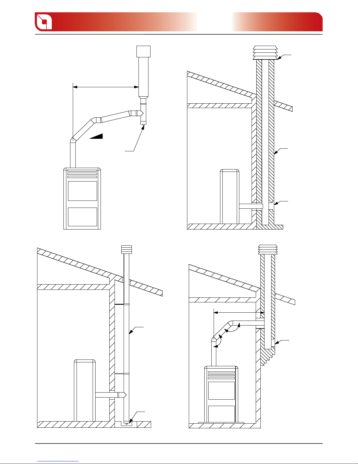
< 3 m
3 - 5 %
< 3 m
45°
45°
14
Chapter5
ASSEMBLY AND INSTALLATION INSTRUCTIONS
Inspection
Windproof
chimney cap
Flue
Inspection
External
insulated
duct
Inspection
Inspection
gure 5.5 gure 5.6
gure 5.7 gure 5.8

50 cm
< 5 m
> 5 m
< 5 m
5
0
H min
β
15
ASSEMBLY AND INSTALLATION INSTRUCTIONS
Chapter5
CONNECTION TO THE FLUE AND COMBUSTION PRODUCT EXHAUST VENTING
The ue must receive exhaust from a single heat generator.
Direct discharge towards enclosed areas, even when roo ess, is forbidden.
Direct discharge of combustion products must take place on the roof and the exhaust duct must have the
features set forth in the section “Chimney or single ue”.
CHIMNEY CAP
The chimney cap must meet the following requirements:
have an internal section equivalent to that of the chimney;
have a useful outlet section no less than twice the internal section of the chimney;
be constructed in such a way as to prevent the penetration of rain, snow and foreign bodies into the
chimney, as well as to assure the discharge of the combustion products also in the presence of winds
coming from any direction and at any angle.
be positioned in such a way as to assure proper dispersion and dilution of the combustion products
and, in any case, outside the re ux area in which the formation of counter-pressure is most likely to occur.
This area has di erent sizes and shapes depending on the slope of the roof; therefore, it is necessary to
use the minimum heights indicated in the gures below.
The chimney cap must not have any mechanical suction devices.
SLOPED ROOF
FLAT ROOF
Distance > A
Distance < A
50 cm beyond the ridge beam
REFLUX AREA
Re ux area height
gure 5.9
gure 5.10
 Loading...