

Page 1

COMFORT IDRO
THERMO PRODUCT USER MANUAL
ENGLISH/INGLESE
Page 2

ENGLISH
We thank you for having chosen our company; our product is a great heating solution developed from the
most advanced technology with top quality machining and modern design, aimed at making you enjoy
the fantastic sensation that the heat of a ame gives, in complete safety.
2
Page 3

INDEX
ENGLISH
ENGLISH .....................................................................................................................................................................................................................................4
WARNINGS ........................................................................................................................................................................................................ 4
SAFETY .............................................................................................................................................................................................................. 4
ROUTINE MAINTENANCE ................................................................................................................................................................................ 4
DEVICES ............................................................................................................................................................................................................ 5
REFERENCE STANDARDS ................................................................................................................................................................................ 5
GENERAL ........................................................................................................................................................................................................................................................ 6
INSTALLATION ..................................................................................................................................................................................................7
FUMES EXHAUST SYSTEM............................................................................................................................................................................... 8
GENERAL REQUIREMENTS ...................................................................................................................................................................................................................... 8
SMOKE DUCT ............................................................................................................................................................................................................................................... 9
CHIMNEY ......................................................................................................................................................................................................................................................11
CHIMNEY CAPS .........................................................................................................................................................................................................................................11
FUMES EXHAUST SYSTEM PRODUCT REQUIREMENTS .............................................................................................................................................................12
COMBUSTION PRODUCTS OUTLET QUOTA ..................................................................................................................................................................................12
TECHNICAL INSTALLATION DOCUMENTATION ...........................................................................................................................................................................13
HYDRAULIC SYSTEM ...................................................................................................................................................................................... 14
INSTALLATION AND SAFETY DEVICES .............................................................................................................................................................................................14
SAFETY DEVICES FOR CLOSED VESSEL SYSTEM ..........................................................................................................................................................................14
DISTANCES OF SAFETY DEVICES ACCORDING TO THE STANDARD .....................................................................................................................................14
TYPE OF SYSTEM ............................................................................................................................................................................................ 15
CLOSED VESSEL PLANT .........................................................................................................................................................................................................................15
SAFETY VALVES .........................................................................................................................................................................................................................................15
CLOSED EXPANSION VESSEL ...............................................................................................................................................................................................................16
COMMISSIONING CHECKS ....................................................................................................................................................................................................................16
AUTOMATIC THERMOSTATIC MIXER VALVE (MANDATORY) ....................................................................................................................................................16
HYDRAULIC PLANT BASIC LAYOUT..............................................................................................................................................................17
FEATURES........................................................................................................................................................................................................ 18
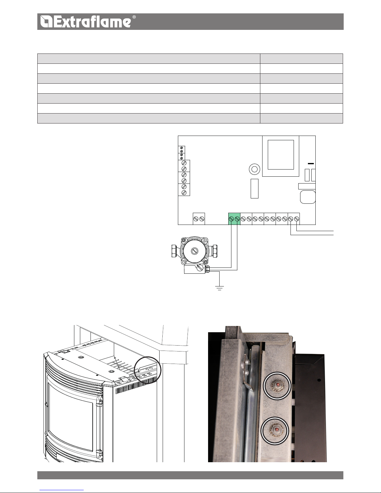
CIRCULATOR CONNECTION IN BOARD ........................................................................................................................................................ 18
REARMS ........................................................................................................................................................................................................... 18
INSERTO COMFORT IDRO INSTALLATION ................................................................................................................................................... 19
MINIMUM DIMENSIONS .......................................................................................................................................................................................................................19
AIR CIRCULATION PIPES ................................................................................................................................................................................ 20
ASSEMBLY WITH SLIDING BASE ..........................................................................................................................................................................................................22
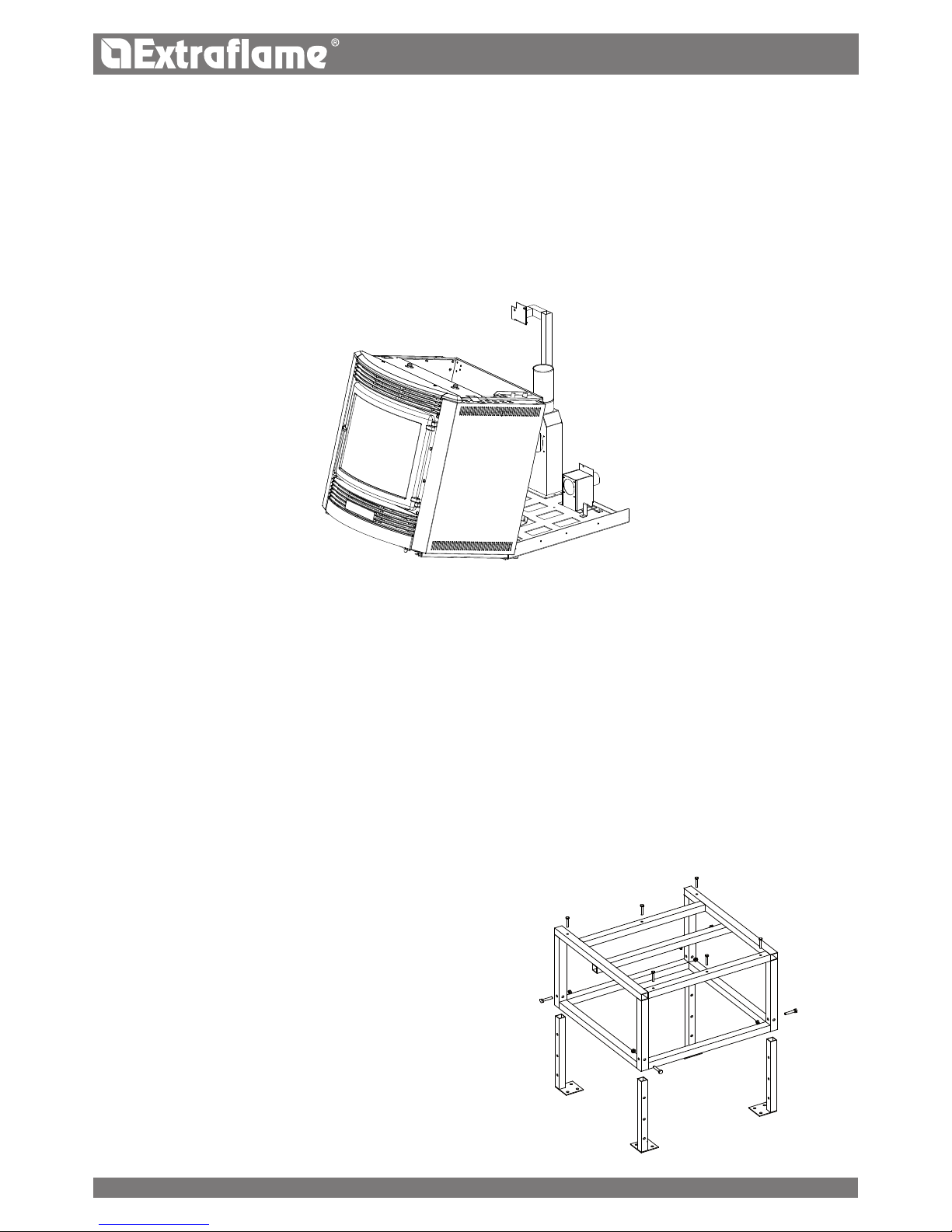
PEDESTAL ASSEMBLY (OPTIONAL): ............................................................................................................................................................. 22
INSTALLATION OF THE HYDRAULIC PART ................................................................................................................................................... 23
FRAMES ........................................................................................................................................................................................................... 26
PELLETS AND FEEDING ................................................................................................................................................................................. 27
FRONT PELLET FEEDING KIT (OPTIONAL) ...................................................................................................................................................27
CONTROL PANEL ............................................................................................................................................................................................ 28
DISPLAY ICONS KEY .................................................................................................................................................................................................................................28
GENERAL MENU ............................................................................................................................................................................................. 29
BASIC INSTRUCTIONS ............................................................................................................................................................................................................................29
REMOTE CONTROL ......................................................................................................................................................................................... 30
TYPE AND REPLACEMENT OF BATTERIES .......................................................................................................................................................................................30
COMMISSIONING SETTINGS ......................................................................................................................................................................... 30
ADJUSTING TIME, DAY, MONTH AND YEAR ................................................................................................................................................ 30
ADJUSTING LANGUAGE.........................................................................................................................................................................................................................30
OPERATION AND LOGIC ................................................................................................................................................................................ 31
ADDITIONAL THERMOSTAT .......................................................................................................................................................................... 32
ADDITIONAL THERMOSTAT FUNCTIONING WITH STBY ACTIVE ...........................................................................................................................................32
ADDITIONAL THERMOSTAT FUNCTIONING WITH STBY DEACTIVATED .............................................................................................................................32
ADDITIONAL THERMOSTAT INSTALLATION ...................................................................................................................................................................................32
USER MENU..................................................................................................................................................................................................... 33
SET THERMOSTAT .....................................................................................................................................................................................................................................33
ENABLE FAN ................................................................................................................................................................................................................................................33
DISPLAY ........................................................................................................................................................................................................................................................33
PELLET FEED ADJUSTMENT .................................................................................................................................................................................................................33
V1- AIR...........................................................................................................................................................................................................................................................34
STAND - BY ..................................................................................................................................................................................................................................................34
KEYS LOCKED .............................................................................................................................................................................................................................................35
RESET .............................................................................................................................................................................................................................................................35
AIR DISCHARGE .............................................................................................................................................................................................. 35
CHRONO .......................................................................................................................................................................................................... 35
PROGRAMMING EXAMPLE ...................................................................................................................................................................................................................36
CLEANING AND MAINTENANCE ...................................................................................................................................................................37
MAINTENANCE ............................................................................................................................................................................................... 37
PERIODIC CLEANING TO BE CARRIED OUT BY THE USER .........................................................................................................................................................37
CLEANING THE HEAT EXCHANGER (MONTHLY) ..........................................................................................................................................................................40
ROUTINE MAINTENANCE CARRIED OUT BY AUTHORISED TECHNICIANS ............................................................................................. 41
PUTTING THE EQUIPMENT OUT OF SERVICE (END OF THE SEASON) .................................................................................................................................41
DISPLAYS ........................................................................................................................................................................................................42
ALARMS .......................................................................................................................................................................................................... 43
3
Page 4

ENGLISH
WARNINGS
This instructions manual is an integral part of the product: make sure that it always accompanies the appliance, even if
transferred to another owner or user, or if transferred to another place. If it is damaged or lost, request another copy from the
area technician. This product is intended for the use for which it has been expressly designed. The manufacturer is exempt from
any liability, contractual and extracontractual, for injury/damage caused to persons/animals and objects, due to installation,
adjustment and maintenance errors and improper use.
Installation must be performed by qualied sta, which assumes complete responsibility for the denitive installation
and consequent good functioning of the product installed. One must also bear in mind all laws and national, regional,
provincial and town council Standards present in the country in which the appliance has been installed, as well as the
instructions contained in this manual.
The Manufacturer cannot be held responsible for the failure to comply with such precautions.
After removing the packaging, ensure that the content is intact and complete. Otherwise, contact the dealer where the appliance
was purchased.
All electric components that make up the product must be replaced with original spare parts exclusively by an authorised aftersales centre, thus guaranteeing correct functioning.
SAFETY
The generator must not be used by persons (including children) with reduced physical, sensory and mental capacities or
who are unskilled persons, unless they are supervised and trained regarding use of the appliance by a person responsible for
their safety.
Children must be checked to ensure that they do not play with the appliance.
Do not touch the generator when you are barefoot or when parts of the body are wet or damp.
The safety and adjustment devices must not be modied without the authorisation or indications of the manufacturer.
Do not pull, disconnect, twist electric cables leaving the stove, even if disconnected from the electric power supply mains.
It is advised to position the power supply cable so that it does not come into contact with hot parts of the appliance.
The power supply plug must be accessible after installation.
Do not close or reduce the dimensions of the airing vents in the place of installation. The airing vents are essential for
correct combustion.
Do not leave the packaging elements within reach of children or unassisted disabled persons.
The hearth door must always be closed during normal functioning of the product.
When the appliance is functioning and hot to the touch, especially all external surfaces, attention must be paid
Check for the presence of any obstructions before switching the appliance on following a prolonged period of inactivity.
The generator has been designed to function in any climatic condition (even critical). In particularly adverse conditions
(strong wind, freezing) safety systems may intervene that switch the generator o. If this occurs, contact the technical aftersales service and always disable the safety systems.
In the event the ue catches re, use suitable systems for suocating the ames or request help from the re brigade.
This appliance must not be used to burn waste
Do not use any ammable liquids for ignition
During the lling phase do not put the bag of pellets to into contact with the product
The majolicas are top quality artisan products and as such can have micro-dots, crackles and chromatic imperfections.
These features highlight their valuable nature. Due to their dierent dilation coecient, they produce crackling, which
demonstrate their eective authenticity. To clean the majolicas, it is recommended to use a soft, dry cloth. If a detergent or
liquid is used, the latter could penetrate inside the crackles, highlighting them.
ROUTINE MAINTENANCE
Based on Decree 22 January 2008 n°37 art.2, routine maintenance means interventions aimed at reducing degradation due to
normal use, as well as dealing with accidental events entailing the need of rst interventions, which however do not modify
the structure of the system upon which one is intervening or its intended use according to the requirements laid down by the
technical standards in force and by the manufacturer's use and maintenance manual.
4
Page 5

ENGLISH
DEVICES
(in the relevant models)
Door micro switch: With the door open, the operation of the
burn pot cleaning system is blocked
Electronic pressure switch: in the event of inadequate pression,
it sends the machine in alarm conditions
F 2.5 A 250 V fuse (stoves): protects the machine from violent
current surges
85°C calibrated mechanical bulb with manual rearm:
intervenes by blocking fuel feed if the pellet tank t° reaches the
limit of 85°C. Rearm must be performed by qualied sta and/
or the manufacturer's technical after-sales assistance.
Pellet tank temperature control probe: if the tank over-heats,
the machine automatically modulates to return to normal
temperature values
Mechanical air pressure switch: blocks the pellet in the event of
insucient depression
REFERENCE STANDARDS
The installation must be in compliance with:
UNI 10683 (2012) heat generators fed with wood and
other solid fuels: installation.
The chimneys must be in compliance with:
UNI EN 13063-1 and UNI EN 13063-2, UNI EN 1457, UNI
EN 1806 in the event of non-metallic chimneys:
EN 13384-1 (13384) chimneys. Thermal and uid dynamic
calculation methods.
UNI EN 1443 (2005) chimneys: general requirements.
UNI EN 1457 (2012) chimneys: clay/ceramic ue liners.
UNI/TS 11278 (2008) Metal - chimneys/ue liners/ue
ducts.
UNI 7129 point 4.3.3 Fire Brigade provisions, local rules
and regulations.
NATIONAL, REGIONAL, PROVINCIAL AND TOWN
COUNCIL REGULATIONS
One must also bear in mind all laws and national, regional,
provincial and town council Standards present in the country
in which the appliance has been installed.
TERMS AND DEFINITIONS
Aeration: Air renewal is required both for the disposal of
the combustion products, and to prevent mixtures with a
hazardous content of non-combusted gases.
Closed hearth appliance: Appliance designed for operation
with closed combustion chamber.
Forced draught appliance: Appliance with ventilation in the
fumes circuit and combustion with fumes ow at a positive
pressure with respect to the environment.
Chimney: Structure consisting in one or several walls
containing one or several outow airways.
The purpose of this predominantly vertical element is to expel
the combustion products at a convenient height from the
ground.
Smoke duct: Component or components that connect the
outlet of the heat generator to the chimney.
Chimney cap: Device that placed on the chimney outlet
allows the dispersion of the combustion products even in
presence of adverse weather conditions.
Condensation: Liquid products which form when the fumes
temperature is lower or equal to the water dew point.
Ducting pipe: Pipe made up of one or several predominantly
vertical elements, specically suitable for collecting and
expelling the fumes, as well as to withstand the relative
components and any condensate over time,
suitable to be installed in a chimney, existing or new technical
compartment, even in new buildings.
Sealed installation: Installation of an appliance with sealed
operation, so that all the air required for combustion is taken
from outside.
Maintenance: Set of procedures required to ensure and
maintain safety and functionality over time and maintain the
eciency of the system within the prescribed parameters.
Chimney system: Chimney installed using a combination
of compatible components, manufactured or specied by a
sole manufacturer whose product liability covers the entire
chimney.
Fumes exhaust system: Flue gas exhaust system,
independent from the appliance made up of a smoke duct,
chimney or individual ue and chimney cap.
Radiation area: Area immediately in front of the hearth in
which the radiant heat caused by combustion is diused.
Reux area: Area beyond the extrados of the roof in which
overpressure or depressions occur, which may aect the
proper discharge of the combustion products.
5
Page 6

ENGLISH
FUNCTIONAL OPERATIONS DIAGRAM
State of the art installation and proper system operation include a series of activities:
1. Preliminary activities:
Verication of the suitability of the power of the heat generator based on the characteristics of the system
verication of the suitability of the installation site,
verication of the suitability of the fumes exhaust system,
verication of the suitability of the outside air inlets;
2. Installation:
implementation of ventilation and connection to the outer air inlets,
implementation and connection to the fumes exhaust system,
assembly and installation,
electric and hydraulic connections,
installation of insulation,
ignition and operation test,
installation of nishings and coverings;
3. Issue of complementary documentation;
4. Inspection and maintenance.
Other actions may be required in relation to specic requests of the competent authority.
PRELIMINARY ACTIVITIES
GENERAL
Verication of compatibility of the system, of any restrictions required by local administrative regulations, special or conventional
requirements resulting from condominium regulations, constraints, laws or administration deeds must precede any other
assembly or installation operation.
One must especially verify the suitability:
of the installation premises, of the appliances already installed in the installation premises and in the adjacent and
adjoining premises, also powered by dierent fuels, with particular reference to non-compliant installations.
of the fumes exhaust system
of the outside air inlets
SUITABILITY OF THE FUMES EXHAUST SYSTEM
Installation must be preceded by a compatibility test between the appliance and the fumes exhaust system, by verifying:
the existence of documentation relating to the system;
existence and content of the chimney plaque;
suitability of the internal section of the chimney;
absence of obstructions all along the chimney;
predominantly vertical height and development of the chimney;
existence and suitability of the chimney cap;
distance of the outside wall of the chimney and of the smoke duct from
combustible materials;
chimney type and material;
absence of other chimney connections.
6
Page 7

B
C
A
S
ENGLISH
INSTALLATION
Installation in premises with re hazards is forbidden. Installation in residential premises (except for sealed operation appliances)
is also forbidden:
in which there are liquid fuel-operated appliances with continuous or intermittent operation, which draw the combustion
air in the room in which they are installed, or
in which there are type B gas appliances intended for room heating, with or without production of domestic hot water and
in adjacent and adjoining premises, or
in which, in any case, the depression measured during installation between the internal and external environment is
greater than 4 Pa
Installations in bathrooms, bedrooms and studio ats
Installation in bathrooms, bedrooms and studio ats is only allowed for sealed or closed hearth appliances with ducted
combustion air taken from the outside.
Installation premises requirements
The support surfaces and/or points must have a suitable load-bearing capacity to support the weight of the appliance, of the
accessories and coatings.
The adjacent, side and rear walls and the supporting surface must be made of non-combustible material. Installation near
combustible materials or those sensitive to heat is permitted as long as there is a suitable safety distance, which for pellet stoves
is equal to:
REFERENCES INFLAMMABLE OBJECTS NONINFLAMMABLE OBJECTS
A 200 mm 100 mm
B 1500 mm 750 mm
C 200 mm 100 mm
In any case the temperature of the adjacent combustible materials must not reach a temperature equal to or greater than the
room temperature increased by 65°C.
The minimum volume of the premises in which to install the appliance must be greater than 15 m³.
Air inlet
S= oor protection
Flue
Inspection
gure 1 gure 2
7
Page 8
ENGLISH
VENTILATION AND AERATION OF THE INSTALLATION PREMISES
Ventilation is deemed sucient when the room is equipped with air inlets according to the table:
Air inlet
See gure 2
Appliance categories Reference standard
Percentage of the
net opening section with
respect to the appliance fumes
outlet section
Minimum net opening value of
the ventilation duct
Pellet stoves UNI EN 14785 - 80 cm²
Boilers UNI EN 303-5 50% 100 cm²
In any case ventilation is deemed sucient when the pressure dierence between the external and internal environment is
equal to or less than 4 Pa.
In the presence of type B gas appliances with intermittent operation not intended for heating, they must have their own aeration
and/or ventilation opening. The air inlets must meet the following requirements:
they must be protected with grids, metal mesh, etc., but without reducing the net useful section;
they must be made so as to make the maintenance operations possible;
positioned so that they cannot be obstructed;
The ow of clean, uncontaminated air can also be obtained from a room adjacent to that of installation (indirect aeration and
ventilation), as long as the ow takes place freely through permanent openings communicating with the outside.
The adjacent room cannot be used as a garage, warehouse of combustible material or for any other activity with a re hazard,
bathroom, bedroom or common room of the building.
FUMES EXHAUST SYSTEM
GENERAL REQUIREMENTS
The heat generator works in a vacuum and has an output fan for fume extraction. Each appliance must be connected to a suitable
fumes exhaust system and ensure adequate dispersion of the combustion products into the atmosphere. The combustion products
must discharged above the roof. Direct discharge from the wall or towards closed spaces is forbidden, even with clear skies.
In particular, it is forbidden to use exible and extendible metal pipes.
The chimney should only receive the exhaust of the smoke duct connected to the appliance; collective ues or conveying
exhausts from hoods above cooking appliances of any kind, or exhausts from other generators into the chimney itself or smoke
duct are not allowed.
The smoke duct and the chimney must be connected with a continuity solution, in order to prevent the chimney from resting
on the appliance.
It is forbidden to have other air supply channels and pipes for plant engineering transit inside the fumes exhaust systems,
especially if over-sized.
The components of the fumes exhaust system must be chosen in relation to the type
of appliance to be installed in compliance with:
in the event of metal chimneys, UNI/ TS 11278, with particular attention to what is stated in the specication;
in the event of non-metallic chimneys: UNI EN 13063-1 and UNI EN 13063-2, UNI EN 1457, .-UNI EN 1806; considering especially:
temperature class;
pressure class (fumes seal) at least equal to the seal required for the appliance;
moisture resistance (resistance to condensation);
class or level of corrosion and specication of the materials constituting the inner wall in contact with the fumes.
soot re resistance class;
minimum distance from combustible materials
Where due to high eciency a pellet stove has fumes at a temperature of less than 160°C + ambient (see technical data)
it must be resistant to moisture.
The installer of the fumes exhaust system, once the installation is complete and the relevant checks and inspections have been
made, must x the chimney plaque supplied by the manufacturer with the product in a visible manner, near the replace, and
which must be completed with the following information:
8
Page 9
a
a
b.1
b
a
a
a
a
b.1
b.1
b b
OK
OK
ENGLISH
SMOKE DUCT
General requirements
The smoke ducts must be installed in compliance with the following general requirements:
be equipped with at least one sealed outlet for eventual fumes sampling;
they must be insulated if they cross through rooms that are not to be heated or outside the building;
they must not cross rooms in which the installation of combustion appliances is forbidden, nor in other premises
compartmentalised against re or with a re hazard, nor in rooms and/or areas that cannot be inspected;
they must be installed so as to allow normal thermal expansion;
they must be tted to the opening of the chimney without protruding inwards;
the use of exible metal pipes to connect the appliance to the chimney is not allowed;
nominal diameter;
distance from combustible materials, indicated in millimetres, followed by the arrow and ame symbol;
installer data and date of installation.
Every time one must cross combustible materials, the following indications must be complied with:
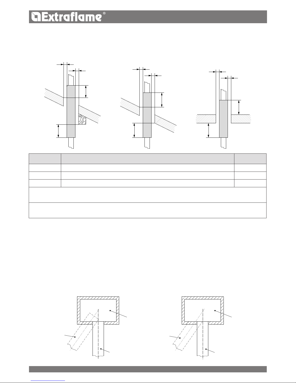
SYMBOL DESCRIPTION QUOTAMM
b Minimum distance of combustible materials from the intrados of the framework/oor/wall 500
b.1 Minimum distance of combustible materials from the extrados of the framework/oor 500
a Minimum distance from combustible materials dened by the manufacturer G(xxx)
The single wall pipes are indicated in white.
The insulated double wall chimney systems are indicated in grey.
One can disregard the quota only in the event of using an appropriate heat protection screen (for example: wall plate) to
protect the intrados of the framework/oor
Chimney
Chimney
Incorrect
Correct
9
Page 10

ENGLISH
counter-slope sections are not allowed;
the smoke ducts must have, along their entire length, a diameter that is no less than that of the attachment of the appliance
exhaust pipe; any section changes are allowed only on the inlet to the chimney;
they must be installed so as to limit the formation of condensation and prevent their release from the joints;
they must be positioned at a distance no less than that indicated in the product specications from combustible materials;
the smoke channel/duct must allow to collect the soot and to be cleaned using a swab and inspected after being
disassembled, or through inspection openings when not accessible from inside the appliance.
ADDITIONAL REQUIREMENTS FOR APPLIANCES FITTED WITH AN ELECTRIC FAN FOR FUMES EXPULSION
For the heat generator appliances equipped with electric fan for expelling fumes, the instructions below must be followed:
The horizontal sections must have a minimum upward slope of 3%
The length of the horizontal section must be minimal and, in any case, no longer than 3 metres
The number of direction changes including the one due to the use of the "T" element must not be more than 4.
Ash deposited in
the 90° bend
Ash deposited in
the 90° bend
Installation with internal ue
Protection from
rain and wind
Protection from
rain and wind
Insulated ue
Insulated
condensationproof "T" tting
with inspection
plug
Condensation-proof
"T" tting with
inspection plug
Insulated ue
Installation with internal - external
ue
IT IS NOT RECOMMENDED TO INSTALL A 90° BEND AS THE FIRST INITIAL PART, SINCE THE ASH WOULD BLOCK THE
PASSAGE OF THE FUMES IN A SHORT TIME, CAUSING PROBLEMS TO THE GENERATOR DRAUGHT.:
EXAMPLES OF CORRECT CONNECTION TO THE CHIMNEY
10
Page 11

3 - 5%
Max 3 mt
ENGLISH
It is mandatory to use airtight pipes.
CHIMNEY
In addition to the general requirements, the chimneys for releasing combustion products into the atmosphere must:
operate under negative pressure (operation under positive pressure is not allowed);
have a preferably circular internal section; square or rectangular sections must have rounded corners with a radius of no
less than 20 mm (hydraulically equivalent sections may be used, as long as the ratio between the longer side and the shorter
side of the rectangle, which circumscribes the section, is in any case no greater than 1.5);
be designed for fumes be designed for fumes expulsion;
be predominantly vertical and have no narrowing along their entire length;
have no more than two direction changes with a slope angle no greater than 45°;
be tted with, in the event of operating in damp conditions, a device for reux drainage (condensation, rainwater);
Ducted system
A ducted system can be installed with one or more ducts, operating only with negative pressure with respect to the environment.
The exible hose compliant with UNI EN 1856-2, with T400-G characteristics, meets the requirements.
CHIMNEY CAPS
The chimney caps must meet the following requirements:
they must have a useful outlet section no less than double of that of the chimney/ducted system on which it is installed;
they must be adapted in order to prevent the penetration of rain and snow in the chimney/ducted system;
they must be built so that, in the event of winds coming from all directions and from any angle, the expulsion of combustion
products is in any case ensured;
they must be free from mechanical intake aids.
"T" tting with
inspection
plug
Steel plate,
airtight
Insulated "T"
tting with
inspection plug
Protection from rain
and wind
Protection from rain
and wind
"T" tting with
inspection plug
EXAMPLES OF CORRECT CONNECTION TO THE CHIMNEY
11
Page 12

90°
c
a
ß
ENGLISH
The outlet of a chimney/ducted system must not be near obstacles that may create turbulence areas and/or prevent proper
expulsion of combustion products and maintenance operations to be carried out on the roof.
Verify the presence of other chimney caps or skylights and dormers.
FUMES EXHAUST SYSTEM PRODUCT REQUIREMENTS
Temperature class
In the event of a pellet appliance, temperature classes below T200 are not allowed.
Soot re resistance class
The fumes exhaust system interlocked with appliances supplied by solid fuels require soot re resistance, and the specication
must be indicated by the letter G followed by the distance from combustible materials in millimeters (XX) (in compliance with
UNI EN 1443) .
In the event of pellet appliances, the fumes exhaust systems must be airtight; if double designation elements are used (G and
O, with or without seal elastomer) for connecting the appliance to the chimney, one must comply with the minimum distance
XX in millimeters, indicated for designation G; in the event of re due to soot, one must ensure the restoration of the initial
conditions (by replacing the gaskets and damaged items and cleaning those remaining in use).
Ignition tests
Operation of the appliance must be veried with an ignition test, i.e.:
for mechanical feed appliances, one must complete the ignition test, verify proper operation for at least the next 15
minutes and adjust the switch-o;
For appliances installed in a hot water heating system (closed replaces, thermo-stoves), testing must also extend to the entire
hydraulic circuit.
COMBUSTION PRODUCTS OUTLET QUOTA
The outlet quota is determined by measuring the minimum height between the roof covering and the lower point of the fumes
expulsion section into the atmosphere; this quota must be outside the reux area and at an adequate distance from obstacles
which hinder or make the expulsion of the combustion products dicult or from openings or accessible areas.
Reux area
The outlet quota must be outside the reux area calculated according to the indications below.
Near the ridge one considers the lowest between the two.
Buer area for outlet quota
Clear area for outlet quota above the roof slope ( ß >10°)
REFERENCE DESCRIPTION CLEAR AREA MM
c Distance measured at 90° from the roof surface 1300
a Height above the ridge of the roof 500
12
Page 13

ENGLISH
Coverings and nishings
The coverings and nishings must only be applied after having veried the proper operation of the appliance according to the
indicated modalities
TECHNICAL INSTALLATION DOCUMENTATION
When installation is complete, the installer must provide the owner or person acting for him, according to the legislation in
force, with the declaration of conformity, supplied with:
1) the use and maintenance manual of the appliance and of the system components (such as for example, the smoke ducts,
chimney, etc.);
2) photocopy or photograph of the chimney plaque;
3) system booklet (where applicable).
The installer must ask to be issued with a receipt stating that the documentation has been provided, and must keep it with a copy of
the technical documentation relating to the installation.
Installation performed by several parties
If the individual installation steps are carried out by dierent parties, each must document the work carried out for the customer
and the for the operator working on the next step.
INSPECTION AND MAINTENANCE
Frequency of operations
Maintenance of the heating system and of the appliance must be carried out on a regular basis according to the table below:
TYPE OF APPLIANCE INSTALLED <15kW (15- 35) kW
Pellet operated appliance 1 year 1 year
Water operated appliances
(closed replaces, thermo-stoves, thermo-kitchens)
1 year 1 year
Boilers 1 year 1 year
Fumes exhaust system 4 t of fuel used 4 t of fuel used
For further details refer to the "cleaning and maintenance" chapter.
Inspection and maintenance report
At the end of the inspection and/or maintenance operations, a report must be issued and released to the owner, or person
acting for him, who must conrm its receipt in writing. The report must indicate the situations encountered, the action taken,
any components replaced or installed and any comments, recommendations and requirements.
The report must be kept with the relative documentation.
In the inspection and maintenance report one must mention:
anomalies detected that cannot be removed, which pose a risk to the safety of the user or serious damage to building;
components that have been tampered with.
If anomalies as per above were detected, the owner, or person acting for him, must be warned in writing, in the maintenance
report, to refrain from using the system until the safety conditions have been fully restored.
The inspection and maintenance report must include the main information of the technician or company who performed the
inspection and/or maintenance operations, with their contact details, date of intervention and the signature of the operator.
13
Page 14
ENGLISH
HYDRAULIC SYSTEM
Certain concepts referring to the Italian UNI 10412-2 (2009) Standard are described in this chapter.
As previously described, when installing, all national, regional, provincial and town council Standards in force provided by the
country in which the appliance has been installed must be complied with.
During installation of the stove it is MANDATORY to adjust the system with a manometer in order to display the water pressure.
INSTALLATION AND SAFETY DEVICES
The installation, relative system connections, commissioning and inspection of correct functioning must be carried out perfectly,
in total compliance with Standards in force, both national, regional and municipal, as well as these instructions.
For Italy, installation must be carried out by professionally authorised sta (Ministerial Decree dated 22.01.08 n°37).
The manufacturer declines all responsibility for damages to objects and/or persons caused by the system.
SAFETY DEVICES FOR CLOSED VESSEL SYSTEM
According to the UNI 10412-2 (2009) Standard in force in Italy, the closed systems must have: safety valve, pump control
thermostat, acoustic alarm activation thermostat, temperature indicator, pressure indicator, acoustic alarm, regulation automatic
circuit breaker switch, automatic circuit breaker block switch (block thermostat), circulation system, expansion system, safety
dissipation system incorporated with the generator with thermal safety valve (self-activated), whenever the appliance does not
have a temperature self-adjustment system.
DISTANCES OF SAFETY DEVICES ACCORDING TO THE STANDARD
The temperature safety sensors must be in place on the machine at a distance no greater than 30 cm from the ow connection.
TABLE OF DEVICES FOR CLOSED VESSEL SYSTEM, PRESENT AND NOT PRESENT IN THE PRODUCT
Safety valve
R
Pump control thermostat (managed by the water probe and board program)
R
Acoustic alarm activation thermostat
Water temperature indicator (display)
R
Pressure transducer with display
R
Acoustic alarm
Automatic circuit breater switch (managed by board program)
R
Pressure transducer with minimum and maximum pressure switch alarm
R
Water overheating automatic circuit breaker (blocking thermostat)
R
Circulation system (pump)
R
Expansion system
R
14
Page 15

ENGLISH
Whenever the generators lack a device, those missing can be installed on the generator ow pipe, within a distance no greater
than 1m from the machine.
COMPONENT DISTANCE
Temperature safety sensors On the machine or not exceeding 30 cm
Missing devices because not as per standard Not exceeding one metre, on the ow pipe
The domestic heating appliances with automatic feeding must: be equipped with a fuel block thermostat or with a cooling
circuit set up by the appliance manufacturer.
The cooling circuit must be activated by a thermal safety valve, in order to ensure that the limit temperature set forth by the
Standard is not exceeded.
Connection between the power supply unit and the valve must be free from interceptions.
The pressure upstream from the cooling circuit must be at least 1.5 bar.
TYPE OF SYSTEM
There are two dierent types of system:
Open vessel plant and closed vessel plant.
The product has been designed and realised to work with closed vessel systems.
CLOSED VESSEL PLANT
System in which the water it contains is not in direct or indirect communication with the atmosphere. Generally, the closed
vessel system has one of the following expansion vessels:
Pre-loaded closed expansion vessel with membrane impermeable to the passage of gases.
Automatic closed expansion system with compressor and membrane impermeable to the passage of gases.
Automatic closed expansion system with transfer pump and membrane impermeable to the passage of gases.
Expansion system without diaphragm.
GENERALITY
The closed systems must have:
Safety valve
Pump control thermostat
Acoustic alarm activation thermostat
Temperature indicator
Pressure indicator
Acoustic alarm
Adjustment automatic circuit breaker switch
Automatic circuit breaker switch (block thermostat)
Circulation system
Expansion system
Safety dissipation system incorporated with the generator with thermal safety valve (self-activated), whenever the
appliance does not have a temperature self-adjustment system
SAFETY VALVES
The load capacity of the safety valve must allow the discharge of a quantity of vapour, not lower than: Q / 0.58 [kg/h] where: Q
is the useful outlet power to the generator water expressed in kilowatt. The diameter of the minimum net transversal section
of the valve inlet must not be lower than 15 mm. The valve load pressure, equal to the calibration pressure, increased by the
overpressure, cannot exceed the maximum exercise pressure of the heat generator. The designer must check that the maximum
pressure existing in every point of the system, does not exceed the maximum exercise pressure of its every component . The
safety valve must be connected to the upper part of the heat generator or outlet pipes, very close to the generator. The length
of the piping between the generator coupling and the safety valve must not exceed 1 m. The piping connecting the safety valve
to the heat generator must not be interrupted and must not have, in any point, a cross-section lower than than that of the safety
15
Page 16
1
2
3
ENGLISH
valve inlet or than the sum of the inlet cross-sections, in the event of several valves serving a single pipe. The discharge piping
of the safety valve must be realised in order not to prevent the regular functioning of the valves and not to cause damages to
persons; the discharge must ow immediately near the safety valve and be accessible and visible. The diameter of the discharge
piping must not however be lower than that of the outlet connection of the safety valve. For diameter of outlet connection it is
intended the minimum internal diameter on the valve outlet upstream of the eventual internal threading.
CLOSED EXPANSION VESSEL
Warnings: check that the preload of the expansion vessel is set to 1.5 bar.
The vessel maximum exercise pressure must not be lower than the calibration pressure of the safety valve, increased by
overpressures, characteristic of the same valve, bearing in mind the eventual level dierence between vessel and valve and
the pressure generated by the functioning of the pump. The capacity of the expansion vessel/s is evaluated depending on the
total system capacity as results from the project. The closed expansion vessels must comply with the provisions concerning the
design, manufacturing, conformity assessment and use of pressure appliances. Intercepting objects or section decreases must
be inserted/practiced on the connection piping, which can be constituted by system portions. The insertion of a three-way
intercepting valve which allows connection between the vessel and the atmosphere for maintenance Operations, is allowed.
Such device must be protected against accidental manoeuvres. The connection pipe must be realised in order not to present
scales or deposits storage points. In case of more heat generators which feed the same plant or the same secondary circuit, each
heat generator must be connected directly to the expansion vessel or plant expansion vessels unit, altogether dimensioned
for the total volume of water contained in the same plant or the same independent circuit. Where it is necessary to separate
the individual heat generator from the expansion vessel or expansion vessels unit, a three-way tap must be applied on the
connection piping between the generator and the vessel, in order to ensure, in every position, the connection of the generator
with the expansion vessel or with the atmosphere. The expansion vessels, the connecting pipes, the bleed pipes and drain pipes
must be protected from freezing, where this phenomenon occurs. The solution used for this purpose is described in the design.
COMMISSIONING CHECKS
Before connecting the boiler:
a) wash all system piping in order to remove any residues which might compromise the correct functioning of certain system
components (pumps, valves, etc.).
b) check to verify that the ue has adequate draft, is not narrowed and that other appliances do not discharge into the ue.
This is to prevent unexpected power increases. Only after this control can the ue tting be mounted between the boiler and
the ue. A check of the connections with pre-existing ues is recommended.
AUTOMATIC THERMOSTATIC MIXER VALVE (MANDATORY)
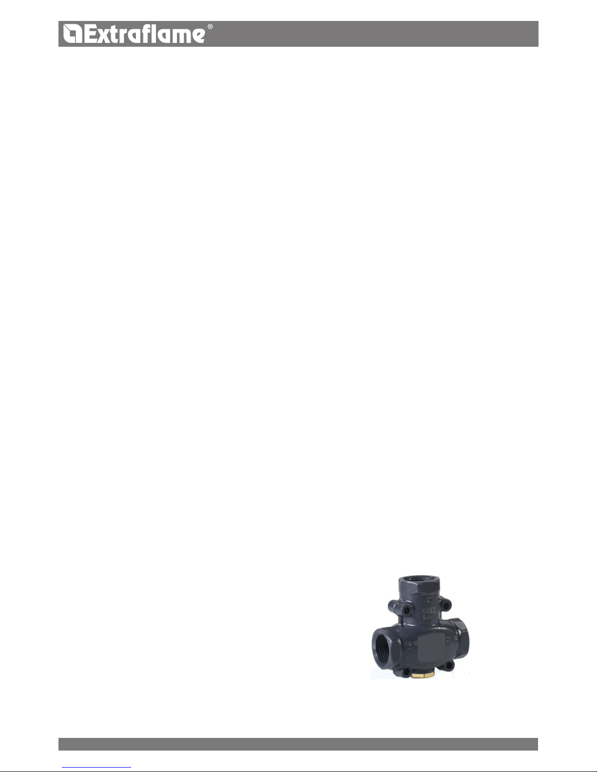
It is required to create an adequate anti-condensation circuit that ensures a return temperature for the appliance of at least 55°
C. The anti-condensation valve, for example, is applied in solid fuel boilers as it prevents the return of cold water in the heat
exchanger.
Routes 1 and 3 are always open and, together with the pump
installed on the return, they guarantee water circulation
inside the biomass boiler exchanger.
A high return temperature allows eciency improvement,
reduces formation of smoke condensation and prolongs the
life span of the generator.
Valves on the market have dierent calibrations. The manufacturer
advises use of model 55°c with 1" hydraulic connections.
Once the valve calibration temperature is reached,
route 2 is opened and the boiler water goes to the system via
the ow.
Valve sold as an accessory (optional)
16
Page 17

1
2
3
T M
G
VB
SI
REAR
S
VE
C
O5 NF
T3
T2
T1
ENGLISH
HYDRAULIC PLANT BASIC LAYOUT
NOTE:
the drawing in the gure is an example.
KEY
A
Primary air inlet
B
Smoke exhaust outlet
*C
Circulator
T1
3 bar safety outlet
T2
Boiler ow / output
T3
Boiler return / inlet
M
Pressure Gauge
T
Thermometer
G
Filling system
S
Safety valve discharge
VB
Balance valve
SI
System exhaust
*VE
Expansion vessel
O5 NF
Board clamp for circulator power supply
* NOT AVAILABLE IN THE THERMO-PRODUCT
IT IS RECOMMENDED TO CONSULT THE TEMPLATES MANUAL ON THIS WEBSITE FOR FURTHER INFORMATION
RELATING TO THE HYDRAULIC CONNECTIONS, AIR INTAKE/FLUE EXHAUST AND DIMENSION SPECIFICATIONS
OF THE PRODUCT IN QUESTION.
Page 18
N
NFO5
N
F
230V/50Hz
N
I3
GND
TC-
TC+
GND
I5
PE
I2
GND
GND
I4
AC1
ENGLISH
FEATURES
Water content of the thermo-product heat exchanger (l) 7
Volume of expansion vessel integrated in the thermo-product (l) /
Maximum content of water in the system for integrated expansion vessel (l)* /
3 bar safety valve integrated in the thermo-product YES
Minimum and maximum pressure switch integrated in the thermo-product YES
Pump integrated in the thermo-product NO
Circulator max. head (m) /
CIRCULATOR CONNECTION
IN BOARD
The gure below shows the inlet - power supply
"O5 NF" for the circulator.
The circulator is not available in the thermoproduct.
REARMS
The gure below illustrates the positions of the tank (85°C) and H2O (100°C) rearms.
Contact the qualied technician if one of the rearms should be triggered, so as to verify the cause.
Page 19

C
A
D
B
50
50
65
735
710
ENGLISH
INSERTO COMFORT IDRO INSTALLATION
The insert is supplied with a sliding metal base that allows it to be installed in a pre-existing ue.
The sliding base allows the easy extraction of the insert both for feeding pellets into the feed-box and for any maintenance or
cleaning at the end of the season. If there is no pre-existing ue, it can be built using the insert support pedestal (optional kit);
in fact, the latter attaches the insert to the oor.
MINIMUM DIMENSIONS
COMPONENTS DESCRIPTION:
A. Primary air intake pipe
B. Flue exhaust pipe
C. Adaptation frame
D. Sliding base and rails
19
Page 20
A
B
C
ENGLISH
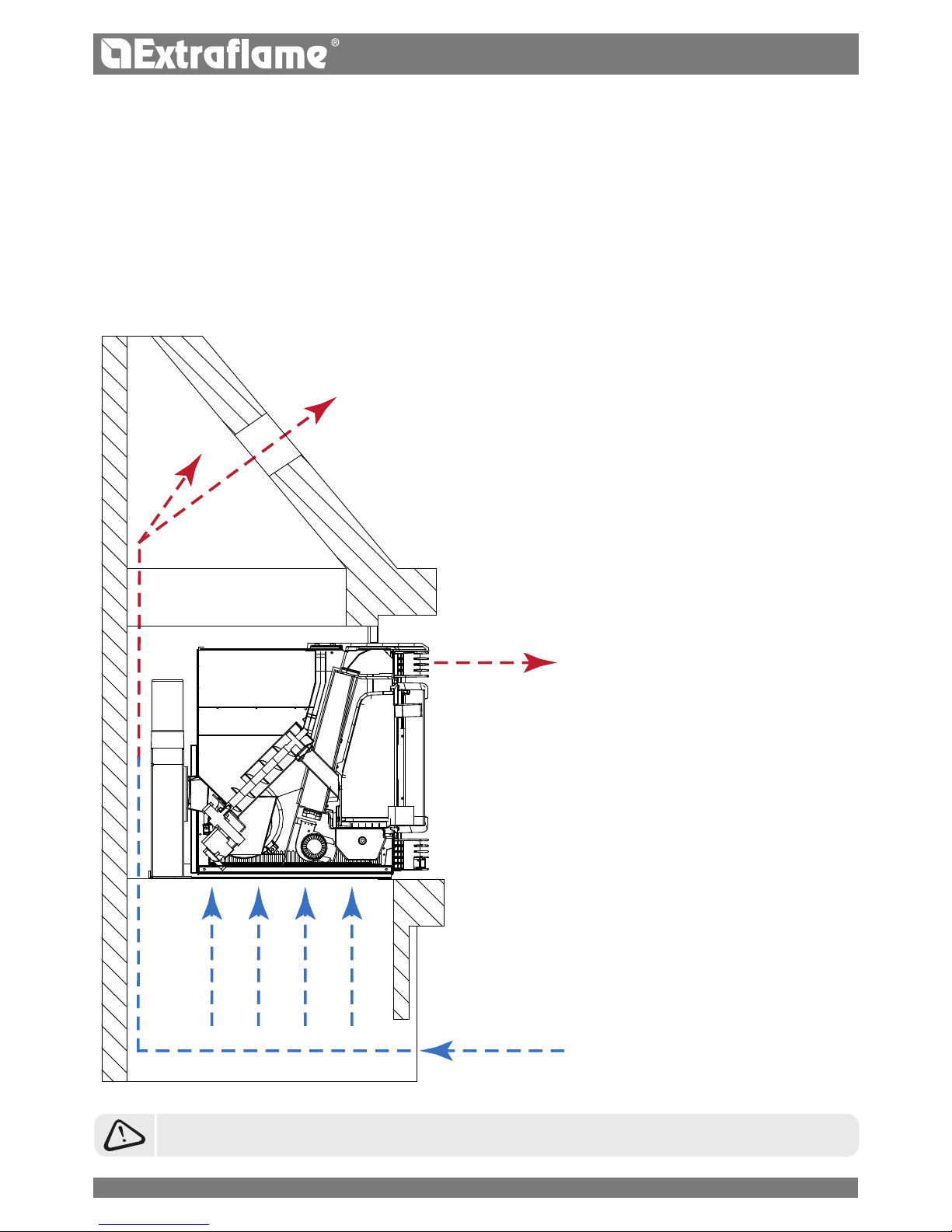
AIR CIRCULATION PIPES
Create air recirculation inside the structure that covers the insert for correct operation. This prevents the appliance from overheating.
To guarantee this, just make one or more openings in the lower and upper parts of the covering.
The following measurements must be respected:
LOWER PART (COLD AIR INLET) WITH TOTAL MINIMUM SURFACE 550 CM².
UPPER PART (HOT AIR OUTLET) WITH TOTAL MINIMUM SURFACE 550 CM².
Reference A
Hot convection air 550 cm²: The heat accumulated inside the covering
must be vented to prevent excessive overheating of the insert.
THE FLUE OUTLET PIPE MUST ALWAYS MAINTAIN A MINIMUM DISTANCE OF 50 MM FROM INFLAMMABLE PARTS.
Reference B
Forced ventilation:
The tangential fan distributes the heat developed by
the insert into the environment.
Reference C
Room air inlet 550 cm²:
To allow air recirculation an air inlet point must be
envisioned, which is preferably positioned in the lower
part of the structure in order to encourage convection.
The air must be withdrawn from the machine's working
environment.
20
Page 21

65
ENGLISH
Make a hole at the base of the ue (gure 1) for air circulation and to ensure the required combustion air for proper insert
combustion.
If it is not possible to make a hole at the centre of the base, make two openings to the sides of the base, equal to the 550cm²
overall lower inlet (2 x 275cm²) (See gure 2).
( gure 1) ( gure 2)
Air inlet
THIS VENTILATION SYSTEM IS TOTALLY INDEPENDENT FROM THE AIR INTAKE FOR COMBUSTION!!
In order for the insert to work properly, observe the measurements contained in the "MINIMUM DIMENSIONS" when building the
chimney that must be made of non-ammable material.
As well as the dimensions of the stove given in the technical features, consider at least 65 mm of air at the back of the insert.
(see gure 3)
Base
Comfort Idro
Base
Comfort Idro
(gure 3)
Air inlet
275cm²
Air inlet
275cm²
21
Page 22
ENGLISH
ASSEMBLY WITH SLIDING BASE
Take the sliding base and position it in the pre-existing ue. Use chalk to mark the blocking holes of the base on the ue surface.
Drill 8 mm holes for the steel expansion inserts.
Make a hole measuring 60 mm in line with the air intake.
Remember the power socket on the rear of the insert so that the plug is accessible once installation is completed.
Fix the base using the clamping screws.
Create a ue exhaust and socket connection respecting the points described previously.
Take the insert, tilt it so that the wheels t into the relative rails, make it run until the ue gas insert is completely inserted into
the ue gas conveyor box.
PEDESTAL ASSEMBLY (OPTIONAL):
Position the base in the desired point and use the feet to adjust the desired height (the bolts are positioned in the four external
sides of the pedestal in the lower part).
Remember the power socket on the rear of the pedestal so that the plug is accessible once installation is completed.
Fix the pedestal to the oor using strong steel plugs with a diameter of 8 mm.
Fix the sliding base to the frame using bolts.
Connect the ue gas exhaust pipe and the air vent as stated in the previous paragraph.
Take the insert, tilt it so that the wheels t into the relative rails, make it run until the ue gas auger is completely inserted into
the ue gas conveyor box.
Finally open the re door and use the supplied Allen key to turn the screw at the bottom left corner clockwise.
To understand whether the insert is correctly attached to the base, connect the plug to the socket and make sure the display
switches on.
N.B.: If our pedestal is used, a slot must be created in the ue that
allows the pellet level in the feed-box to be checked, thus preventing
spillage during lling.
22
Page 23
ENGLISH
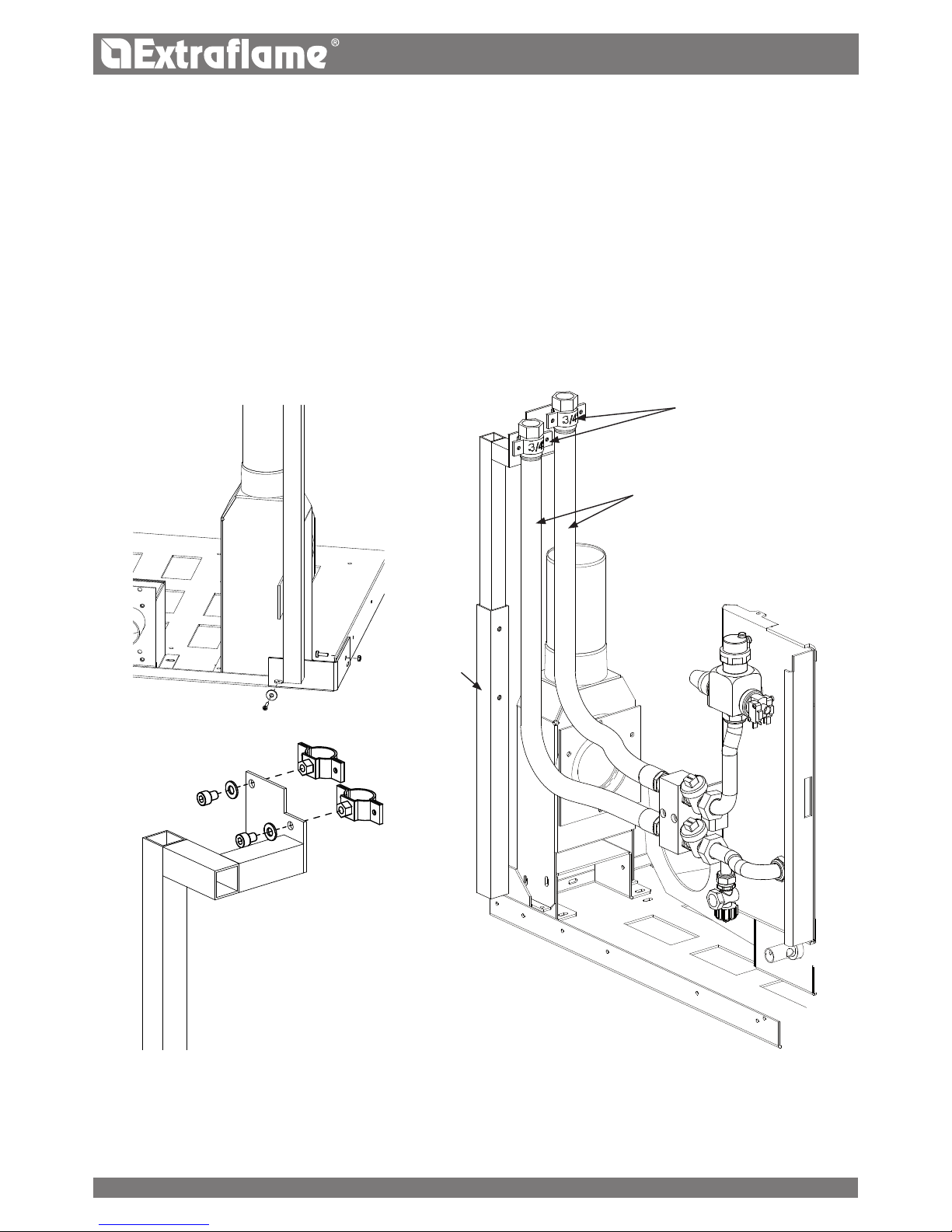
INSTALLATION OF THE HYDRAULIC PART
For the hydraulic connections it is possible to proceed in various ways in relation to the presence or not of the insert covering
structure.
NO COVERING AVAILABLE
When covering is performed after the product has been installed, the connections to the hydraulic plant are made easier due
to freedom of movement.
Before positioning the base in its denitive location, mount the following parts:
the exible pipe support rod, as indicated in gure A by the means of one M5 x 16 screw, the respective galvanised M5
nut and the burnished 3.9 x 22 self-threading screw (the latter must be unscrewed as it is already used to x the ue conveyor
pipe).
The 2 collars with washer (gure B) and burnished TCEI M8 x 10 screw as the latter can only be reached from the rear.
Rod
adjustment
Collars
Figure A
Figure B
Hoses
At this point it is possible to x the base as described previously. Re-position the machine body and connect 2 exible pipes to
the rear support rod using the supplied screws; they will be successively connected to the hydraulic plant. The position of the 2
exible pipes in the collars must be rigorously respected in order to prevent problems during handling.
23
Page 24
ENGLISH
ALREADY EXISTING COVERING
If the insert is installed inside an existing covering, it is possible to proceed in 2 dierent ways:
Create a lateral opening on the left side of the covering to access the hoses at the height of the collars.
If it is not possible to make a lateral opening in the covering, follow the procedure given below.
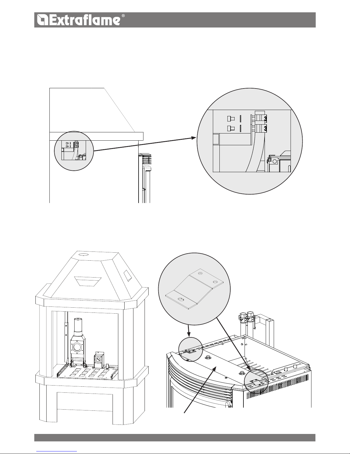
Release the machine body from the base with the sliding rails using the sequence described previously and x the base, having
already previously positioned the rod for the exible pipes. Remove the painted cover by means of the 2 screws in the upper
part that x it and also remove the xing bracket on the left side (see gure 1-2).
Side xing
bracket
Painted cover
Figure 1
Figure 2
24
Page 25
ENGLISH
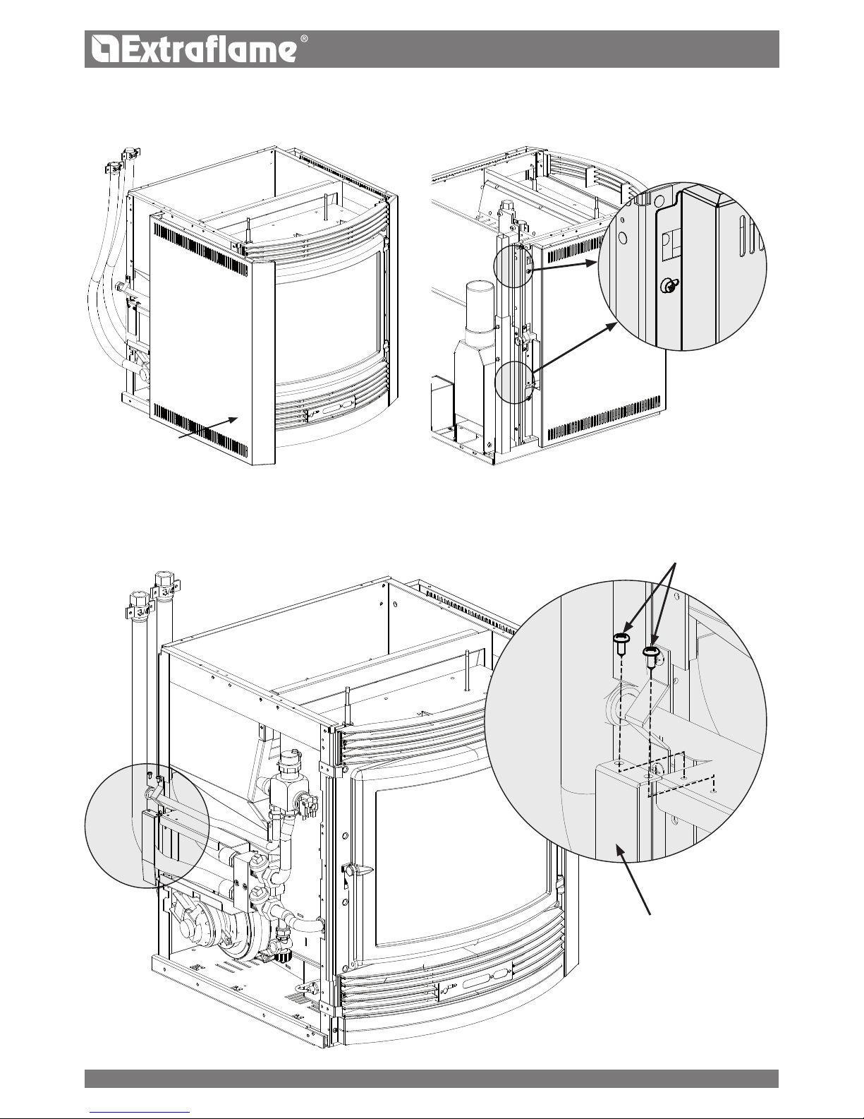
Remove the left side by pushing it forward:
during this operation the rear side must be removed from the screws by slight rotation, using the slots as illustrated in the gure
below.
Remove the exible pipe guide bracket by removing the 2 screws that x it
Left Side
Bracket
Screws
25
Page 26
ENGLISH
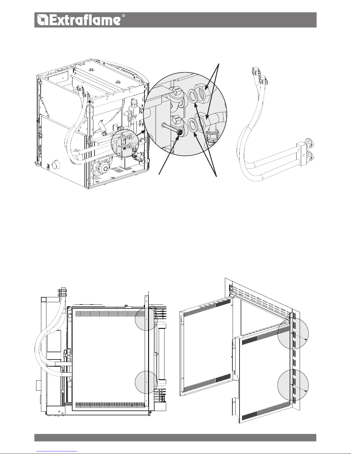
Loosen the ring nuts on the 2 copper pipes and remove the metric screw that xes the brass block to the machine body. At this
point, it is possible to separate the brass block with the pipes from the rest of the insert.
Proceed by connecting the pipes to the support rod and consequently to the system. Re-position the insert into the rails and
restore the initial brass block situation, repeating the operations described above in the reverse order (rst x the block using
the metric screw and then connect the ring nuts paying attention to the gaskets).
Re-mount the exible pipe guide bracket, the left side with the relative blocking rod and the upper cover.
Metric
screw
Gaskets
Ring nuts
FRAMES
The lateral frames must be xed using the 2 supplied burnished 4.2 x 9.5 self-threading screws per side. The 2 sides are already
perforated for xing the frames themselves.
26
Page 27
ENGLISH
THE USE OF POOR QUALITY PELLETS OR ANY OTHER MATERIAL DAMAGES THE FUNCTIONS OF YOUR STOVE AND CAN
VOID THE WARRANTY AND THE ANNEXED RESPONSIBILITY OF THE MANUFACTURER.
TO GUARANTEE COMBUSTION WITHOUT PROBLEMS, THE PELLETS MUST BE KEPT IN A DRY PLACE.
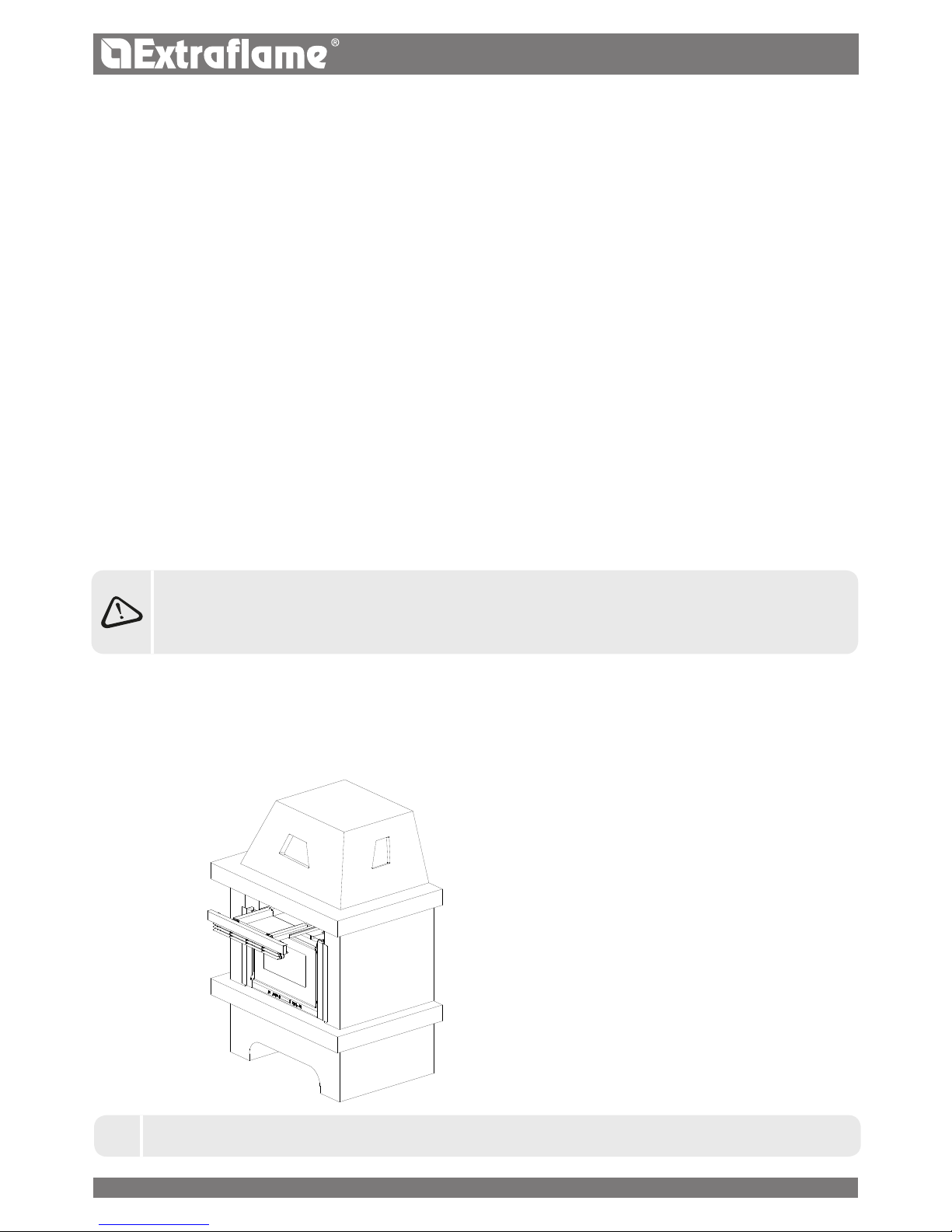
FRONT PELLET FEEDING KIT (OPTIONAL)
The optional pellet feeding kit allows pellets to be fed into the feed-box from the front without having to extract the insert
(operation that requires machine switch-o).
J
IN THE EVENT OF INSTALLATION WITH FEEDING KIT (OPTIONAL) THE MACHINE MUST NOT BE EXTRACTED.
Further information on the accessories is
available on the website in the category
"accessories".
PELLETS AND FEEDING
Pellets are made by subjecting wood shavings i.e. the rejects of pure wood (without paint) sawmill, carpenter products and
products from other activities connected to working and transforming wood, to very high pressures.
This type of fuel is fully ecological as no glues are used to hold it together. In fact, the compactness of the pellets is guaranteed
over time by a natural substance that is found in wood: lignin.
As well as being an ecological fuel, as wood residues are made the most of, the pellet also has technical advantages.
While wood has a caloric value of 4.4 kW/kg. (with 15% humidity, therefore after about 18 months seasoning), that of the pellet
is 5 kW/kg.
Pellet density is about 650 kg/m3 and water content is equal to 8% of its weight. For this reason the pellets do not need to be
seasoned in order to obtain a suciently adequate heat yield.
The pellet used must comply with the features described by Standards:
EN PLUS - UNI EN 14961 - 2 (UNI EN ISO 17225-2) class A1 - A2
The Manufacturer recommends using pellets with a diameter of 6mm with its products.
PELLET STORAGE
To guarantee combustion without problems, the pellets must be kept in a dry place.
27
Page 28

ENGLISH
CONTROL PANEL
BUTTON
ON/OFF
DISPLAY OF VARIOUS
TEXT MESSAGES
DISPLAY
OF POWER
TEMPERATURE SETTING
OPERATION POWER
ADJUSTMENT
DISPLAY ICONS KEY
Indicates the presence of an alarm.
On: indicates the presence of an alarm
O: indicates the absence of alarms
Flashing: indicates the deactivation of the depression
sensor.
It indicates weekly programming functioning
Indicator on = weekly programming active
Indicator o = weekly programming disabled
Indicates the room temperature status
O = the T° read by the probe is above the set temperature
On = the T° read by the probe is below the set temperature
Indicates the stby function
O = Stby deactivated
On = Stby activated
Ignition plug
O = ignition plug active
On = ignition plug deactivated
Flashing = Ignition phase
Additional external thermostat input status
O = open contact
On = closed contact
It indicates fumes motor operation.
O = fumes motor not working
On = fumes motor working
Flashing = breakdown
It indicates the communication between remote control
and stove. Every time a key is pressed on the remote control
the indicator must switch on. If the indicator is always on it
indicates that the communication between remote control
and stove is blocked.*
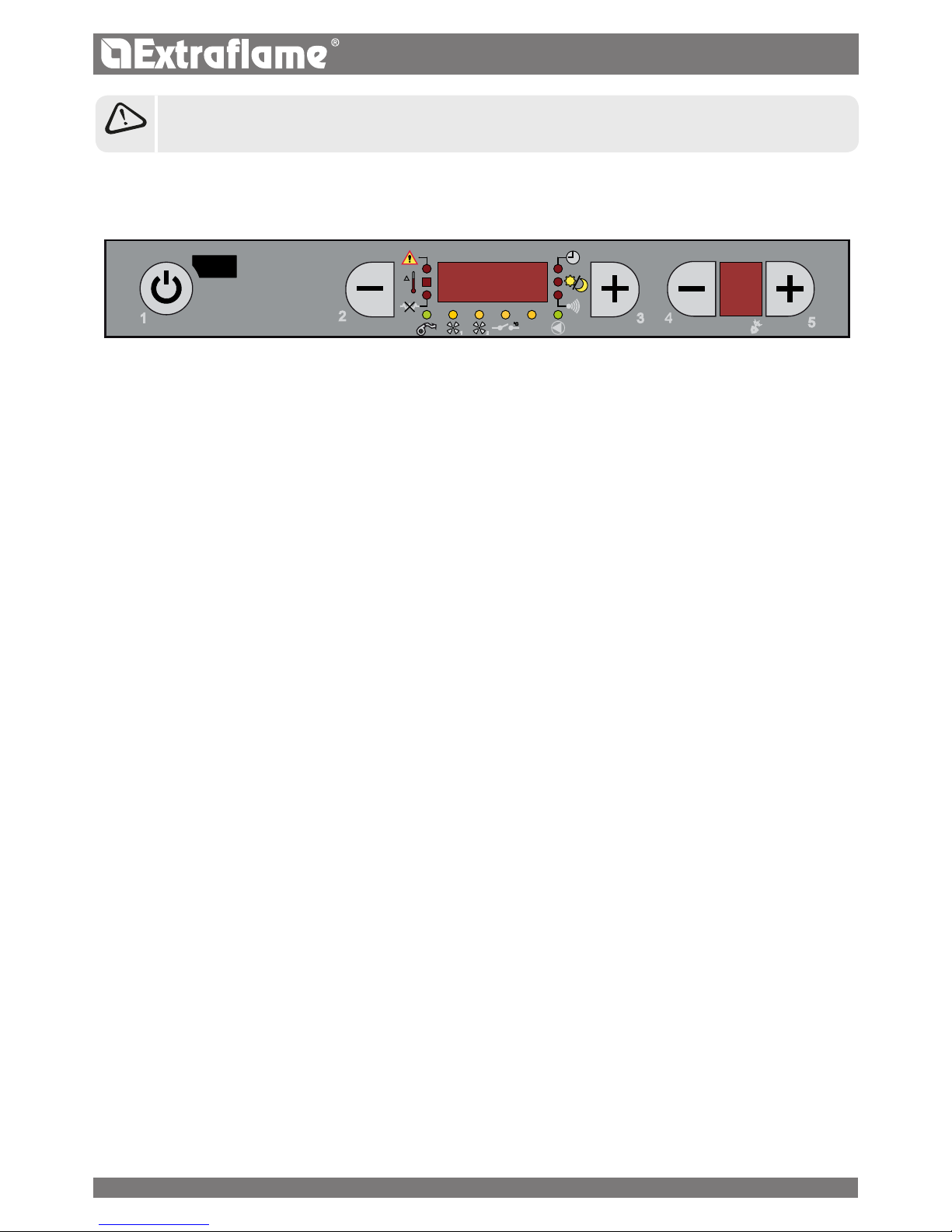
1
It indicates functioning of the tangential fan
O = not working
On = working
Flashing = Motor at minimum
It indicates pump operation
O = pump deactivated
On = pump active
2
Not used
Not used
It indicates pellet feed motor operation
O = pellet feed motor disabled
On = pellet feed motor active
28
Page 29

3
3
3
5
5
5
5
5
5
5
5
5
5
5
5
5
5
5
5
5
5
5
5
5
5
ENGLISH
GENERAL MENU
SET CLOCK
CHRONO SETTING
LANGUAGE
USER
TECHNIC SET
RESERVED TO THE
QUALIFIED TECHNICIAN
ENABLE FAN
ON/OFF
YEAR
MONTH
DATE
MINUTES
HOURS
ENABLE CHRONO
REPEAT THE SAME STEPS FOR
THE OTHER 3 TIME SLOTS
SET PRG1
65 80°C
MONDAY PRG1...
ONOFF
STOP PRG1
START PRG1
DISPLAY
PELLETS
IN %
STAND BY
ONOFF
KEYS LOCKED
ONOFF
IT,EN,FR,DE,ES
SET THERMOSTAT
OFF 06/40°C
CONFIRM
WITH KEY 1
...SUNDAY PRG1
ONOFF
DAY
BASIC INSTRUCTIONS
The following recommendations must be followed the rst
times the stove is ignited:
Faint smells may be produced due to the drying of the
paints and silicones used. Do not remain in the environment
for long periods.
Do not touch the surfaces as they could still be
unstable.
Air the room well several times.
The hardening of the surfaces is terminated after several
heating processes.
This appliance must not be used to burn waste.
Before lighting the stove, the following points must be
veried:
The hydraulic system must be completed in compliance
with the guidelines of the regulations and the manual.
The tank must be full of pellets.
The combustion chamber must be clean.
The burn pot must be completely free and clean.
Check the hermetic closure of the re door and the ash
drawer.
Check that the power supply cable is connected correctly
The bipolar switch in the rear right part must be positioned
on 1.
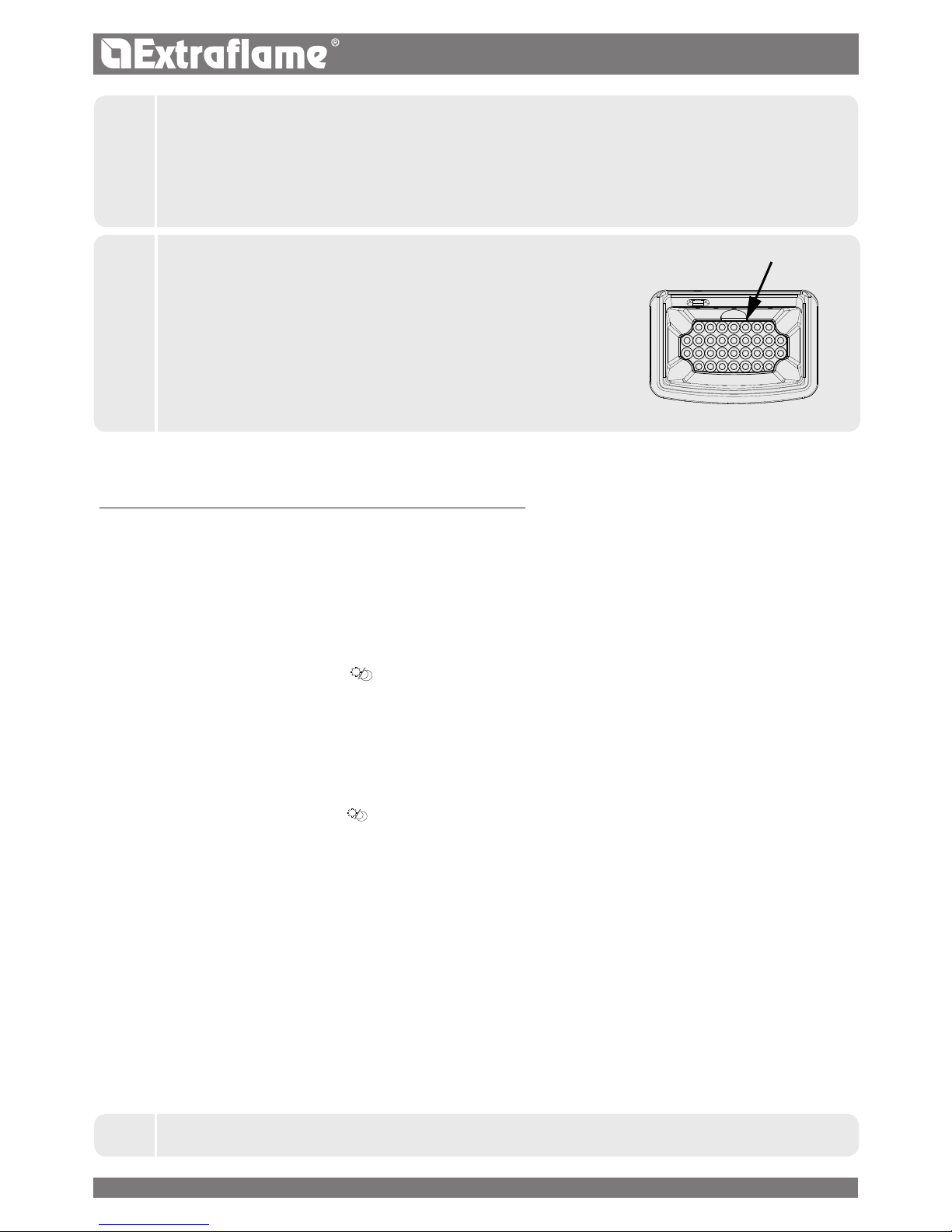
IT IS FORBIDDEN TO USE THE APPLIANCE WITHOUT THE DIVIDER AND/
OR GLASS PROTECTION SEE THE FIGURE TO THE SIDE.
ITS REMOVAL JEOPARDISES THE SAFETY OF THE PRODUCT AND
IMMEDIATELY VOIDS THE WARRANTY PERIOD.
IN THE EVENT OF WEAR OR DETERIORATION CONTACT THE ASSISTANCE
SERVICE TO REPLACE THE PART.
THE REPLACEMENT IS NOT COVERED BY THE PRODUCT WARRANTY AS
IT IS A PART SUBJECT TO WEAR.
BURN POT DIVIDER
GLASS PROTECTION
RESET
ONOFF
V1 AIR
+/ 10%
To conrm parameter/programming and exit.
To set data/parameters.
To progress or return to the menu.
1
2
3
4
5
To access the menu, press and hold button 5
down for a few seconds.
29
Page 30
ENGLISH
ADJUSTING TIME, DAY, MONTH AND YEAR
CONTROLS PROCEDURE
Press key 5 for a few seconds, until the text SET CLOCK
appears.
Confirm using key 5.
Use key 3 to select the day.
Press key 5.
Follow the same procedure (5 to move forward, 3 to set)
to adjust the hours, minutes, day, month and year.
Press key 1 several times to conrm and exit the menu.
SET CLOCK
DAY MON, TUE, WED, ...SUN
HOURS 0...23
MINUTES 00...59
DAT E 1...31
MONTH 1...12
YEAR 00...99
ADJUSTING LANGUAGE
CONTROLS PROCEDURE
Press key 5 for a few seconds, until the text SET CLOCK
appears.
Press key 3 twice until set Language appears.
Conrm using key 5.
Select the language using key 3.
Press key 1 several times to conrm and exit the menu.
LANGUAGE
ITALIAN
ENGLISH
GERMAN
FRENCH
SPANISH
REMOTE CONTROL
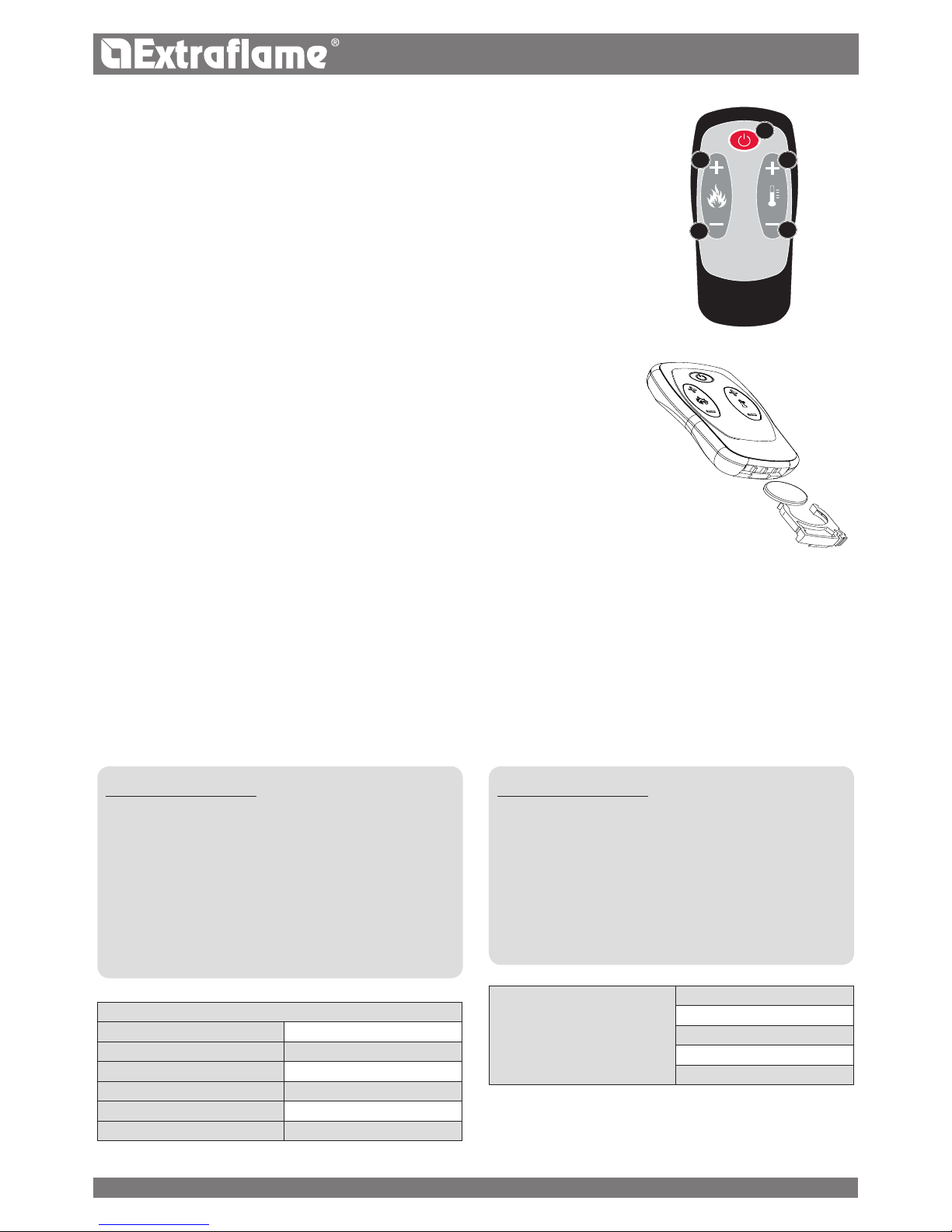
The heating power, the desired room temperature and the appliance ignition/switch
o, can be adjusted using the remote control.
To ignite the stove, press key 1 for a few seconds; the appliance will automatically
enter the ignition phase. It is possible to adjust power by using keys 4 and 5, whereas
the desired temperature can be adjusted using keys 2 and 3. To switch the stove o,
press and hold key 1 for a few seconds.
TYPE AND REPLACEMENT OF BATTERIES
The batteries are housed in the lower part of the remote control.
To replace them, remove the battery holder (as indicated in the gure at the back of
the remote control), remove or
insert the battery following symbols on the remote control and on the battery.
For operation, 1 CR2025, 3V lithium buer battery is required.
The batteries used contain metals harmful for the environment.
Therefore, they must be disposed of separately in appropriate containers.
1
2
34
5
COMMISSIONING SETTINGS
Once the power cable at the back of the stove has been connected, move the switch, also located on the back, to (I).
The switch at the back of the stove powers the stove board.
The stove remains o and a rst screen appears on the panel
reading OFF.
30
Page 31
ENGLISH
DO NOT USE ANY INFLAMMABLE LIQUIDS FOR IGNITION!
DO NOT ALLOW THE BAG OF PELLETS TO COME INTO CONTACT WITH THE BOILING HOT STOVE DURING THE FILLING PHASE!
IN THE EVENT OF CONTINUOUS NO IGNITION, CONTACT AN AUTHORISED TECHNICIAN.
OPERATION AND LOGIC
IGNITION
Once the points listed previously have been checked, press key 1 for three seconds to ignite the stove.
15 minutes are available for the ignition phase. After ignition and having reached the control temperature, the stove interrupts
the ignition phase and passes to STARTING.
STARTING
During the start-up stage, the stove stabilises combustion, increasing it gradually, to then start ventilation and switch to the
WORK mode.
WORK
During the work phase, the stove reaches the set power; see following item.
ADJUSTING POWER SETTING
Set the functioning power from 1 to 5 (settable using keys 2 - 3).
Power 1 = minimum level - Power 5 = maximum level.
H2O TEMPERATURE SET ADJUSTMENT
Set the boiler temperature from 65 - 80°C (settable using keys 4 - 5).
PUMP OPERATION
The pump activates water circulation when the temperature of the water inside the stove reaches approx. 60°C. As the pump
always functions above 60°, an always-open heating area is recommended to make product functioning homogeneous,
avoiding overheating blocks. Normally this area is dened as a “Safety zone”.
ENVIRONMENTAL TEMPERATURE in the applicable models)
The front ventilation can be activated/deactivated and the room temperature controlled by means of the room probe (as per
standard). (See the ''enable fan'' chapter on the following pages.)
BURN POT CLEANING
During the work stage, the stove has an internal counter which cleans the burn pot after a set amount of time.
This stage will be shown on the display, it will bring the stove to a lower power level and will increase the fumes motor for a
programmed amount of time. When the cleaning stage is nished, the stove will continue its work, going back to the selected
power level.
MODULATION and H-OFF
As the water temperature approaches the set point, the boiler starts to modulate automatically bringing itself to the minimum
power.
If the temperature increases beyond the set point, it will automatically switch o indicating HOFF and will automatically go
back on when the temperature drops below the set point.
SWITCHOFF
Press key 1 for three seconds.
When the operation has been performed, the appliance automatically enters the switch-o phase, blocking the supply of pellets.
The fumes motor and the hot air ventilation motor will remain on until the temperature of the stove has dropped below
the factory parameters.
REIGNITION
The stove can only be re-ignited automatically or manually when the cooling cycle conditions and the preset timer have been
satised.
31
Page 32
ENGLISH
ADDITIONAL THERMOSTAT
N.B. : Installation must be performed by an authorised technician.
There is a possibility to thermostat a room adjacent to the room where the stove is positioned: just connect a thermostat
following the procedure described in the next step (it is recommended to position the optional mechanical thermostat at a
height of 1.50 m from the oor) . Stove functioning with the external thermostat connected in the STBY clamp can be dierent
on the basis of the activation or disabling of the STBY function.
The STBY clamp leaves the factory jumpered, therefore it is always with closed contact (on request).
ADDITIONAL THERMOSTAT FUNCTIONING WITH STBY ACTIVE
When the STBY function is activated, the LED ashes. When the contact or external thermostat is satised (open contact
/ temperature reached), the stove will switch o. As soon as the contact or external thermostat switches to the "not satised"
status (closed contact/temperature to be reached) it will re-ignite.
N.B.: stove operation depends on the temperature of the water inside the stove and relative factory setting restrictions.
If the stove is in H OFF (water temperature reached), any additional contact or thermostat request will be ignored.
ADDITIONAL THERMOSTAT FUNCTIONING WITH STBY DEACTIVATED
When the STBY function is disabled, the LED is xed.
When the contact or external thermostat is satised (open contact / temperature reached), the stove will go to minimum. As
soon as the contact or external thermostat switches to the "not satised" status (closed contact / temperature to be reached)
the stove will start to work again at the pre-set power.
N.B.: stove operation depends on the temperature of the water inside the stove and relative factory setting restrictions.
If the stove is in H OFF (water temperature reached), any additional contact or thermostat request will be ignored.
ADDITIONAL THERMOSTAT INSTALLATION
Switch the appliance o using the master switch positioned on the rear of the stove.
Remove the plug from the socket.
Refer to the electrical layout to connect the two thermostat cables to the relative clamps positioned on the rear of the
machine, one is red and the other black (STBY clamp).
The image is given as an example.
J
REFER TO THE CHAPTER IN THE ''USER MENU'' TO ACTIVATE STAND BY
J
NO IGNITION
FIRST IGNITION COULD EVEN FAIL AS THE AUGER IS EMPTY AND IS NOT ALWAYS ABLE TO LOAD THE BURN POT
WITH THE REQUIRED AMOUNT OF PELLETS ON TIME TO REGULARLY START THE FLAME.
IF THE PROBLEM OCCURS AFTER ONLY A FEW MONTHS WORKING, CHECK THAT ROUTINE CLEANING STATED IN THE
STOVE BOOKLET, HAS BEEN CARRIED OUT CORRECTLY.
J
CLEAN CHECK UP 1 2
SHOULD THE ''CLEAN CHECK UP'' ALARM BE TRIGGERED, MAKE SURE THAT
THE BOTTOM OF THE BURN POT IS FREE OF RESIDUE OR BUILDUP. THE
HOLES AT THE BOTTOM MUST BE COMPLETELY FREE TO GUARANTEE
CORRECT COMBUSTION. SEE CHAPTER "CLEANING UNDER USER'S
RESPONSIBILITY"
THE "PELLET FEED REGULATION" FUNCTION CAN BE USED TO ADJUST
COMBUSTION BASED ON THE DESCRIBED REQUIREMENTS. IF THE ALARM
PERSISTS AND THE ABOVE LISTED CONDITIONS HAVE BEEN CHECKED,
CONTACT THE QUALIFIED AFTERSALES ASSISTANCE CENTRE.
BURN POT BOTTOM
32
Page 33

ENGLISH
PELLET FEED ADJUSTMENT
The following menu allows the user to adjust the percentage of pellet feed.
If the stove has functioning problems owing to the quantity of pellets, adjust pellet feeding directly from the control board.
The problems correlated to the amount of fuel can be divided into 2 categories:
CONTROLS PROCEDURE
Press key 5 for a few seconds, until SET CLOCK appears.
Press key 3 until SET USER appears.
Conrm using key 5.
Use buttons 2 -3 to select the room temperature.
Press key 1 several times to conrm and exit the menu.
ENABLE FAN
This menu allows you to enable or disable the operation of the tangential fan.
CONTROLS PROCEDURE
Press key 5 for a few seconds, until SET CLOCK appears.
Press key 3 until SET USER appears.
Conrm using key 5.
Hold key 5 down until ENABLE FAN appears.
Use keys 2-3 to enable/disable ventilation.
Press key 1 several times to conrm and exit the menu.
1
DISPLAY
This menu allows the user to adjust the brightness of the display. The possible settings range from 10 to 31.
CONTROLS PROCEDURE
Press key 5 for a few seconds, until SET CLOCK appears.
Press key 3 until SET USER appears.
Conrm using key 5.
Hold key 5 down until DISPLAY appears.
Use keys 2 -3 to adjust the brightness of the display.
Press key 1 several times to conrm and exit the menu.
USER MENU
SET THERMOSTAT
The following menu allows you to set the room temperature of those products equipped with front fan. Once the set temperature
is reached the fan will run at minimum speed.
The possible settings are: OFF - 06 ...40°C. The room temperature will be displayed alternately with the water temperature on
the display.
33
Page 34
ENGLISH
CONTROLS PROCEDURE
Press key 5 for a few seconds, until the text SET CLOCK appears.
Press key 3 UNTIL set user appears.
Conrm using key 5.
Hold key 5 down until PELLET appears.
Use keys 2 -3 to adjust the pellet feed.
Press key 1 several times to conrm and exit the menu.
STAND BY
The Stby function is used if immediate stove switch-o or modulation via additional external thermostat is desired.
CONTROLS PROCEDURE
Press key 5 for a few seconds, until SET CLOCK appears.
Press key 3 until SET USER appears.
Conrm using key 5.
Hold key 5 down until STAND BY appears.
Use keys 2-3 to enable/disable the stby function.
Press key 1 several times to conrm and exit the menu.
V1 AIR
The menu allows the user to adjust the speed of the front fan in percentage.
CONTROLS PROCEDURE
Press key 5 for a few seconds, until SET CLOCK appears.
Press key 3 until SET USER appears.
Conrm using key 5.
Hold key 5 down until V1 FAN appears.
Use keys 2-3 to adjust the front ventilation speed.
Press key 1 several times to conrm and exit the menu.
1
NO FUEL:
the stove can never develop a suitable ame, tending to remain very low even at high power.
at minimum power the stove tends to almost switch-o taking the stove into “NO PELLETS” alarm condition.
when the stove displays the “NO PELLETS” alarm, there may be non-burned pellets inside the burn pot.
EXCESS FUEL:
the stove develops a very high ame even at low power.
the panoramic glass is very dirty, obscuring it almost totally.
the burn pot tends to become encrusted, blocking the holes for air intake due to the excessive pellet feed, as it is only
burned partially.
The adjustment to be performed is in percentages. Therefore changing this parameter will lead to a proportional variation of
all stove feeding speeds. Feeding is from -30% to +20%.
Follow the procedure on the display to perform the procedure:
34
Page 35
ENGLISH
CHRONO
The chrono allows the user to program 4 time spans within a day to use every day of
the week.
The switch-on and switch-o time can be set in every time slot, along with the
days of use of the programmed time slot and the desired water temperature (65
- 80°C).
RECOMMENDATIONS
The ignition and switch-o times must be within the arc of
one day, from 0 to 24 and not over several days:
Before using the chrono function, set the current day and
time. Therefore check that the points listed in the “Set clock”
sub-chapter have been followed, so that the chrono function
works. Aside from programming it, activate it as well.
Example:
Switch-on time 07:00 CORRECT
Switch-o time 18:00
Switch-on time 22:00 INCORRECT
Switch-o time 05:00
KEYS LOCKED
The menu allows the user to lock the display keys (like with mobile phones). Press keys 1 and 5 simultaneously.
When the function is enabled, every time you press a key the message “CONSOLE BLOCKED" appears. Press keys 1 and 5 to
release the console.
CONTROLS PROCEDURE
Press key 5 for a few seconds, until the text SET CLOCK appears.
Press key 3 until SET USER appears.
Conrm using key 5.
Hold key 5 down until CONSOLE BLOCKED appears.
Use keys 2-3 to enable/disable ventilation.
Press key 1 several times to conrm and exit the menu.
RESET
Allows the user to reset all values modiable by the user to the default values. The modied data is the following:
CONTROLS PROCEDURE
Press key 5 and SET CLOCK will appear.
Press key 3 several times until USER is displayed.
Press key 5.
SET THERMOSTAT will appear
Press key 5 until "RESET" appears.
Press keys 3 to select ON and press key 5.
"DONE" will appear on the display to conrm
SET H2O = 75°C
SET TEMPERATURE = 35°C
SET POWER = 5
ENABLE CHRONO = OFF
START PRG1=OFF
STOP PRG1 = OFF
MONDAY PRG1 = OFF
.......all chrono parameters OFF
PELLET = 00%
STAND BY = OFF
AIR DISCHARGE
This function allows the user to bleed any air in the stove. Activates the function: The indicator lights will light up on the circulators on the
display. (the circulators will be powered for 15 minutes and 30 seconds and then will stop for 30 seconds; cut the power to interrupt)
CONTROLS PROCEDURE
Press key 1 and 4 simultaneously.
The password will be required.
Enter code "77" via key 4.
Conrm using key 5.
35
Page 36
ENGLISH
*2ND TIME SLOT SWITCHON
At this point, the second time slot must be programmed.
The sequence to be followed is the same and is repeated as per the 1ST TIME SLOT SWITCHON.
On this occasion simply enter the time, for example start at 15:00 and Stop at 22:00 and to activate the days Saturday and
Sunday by setting them at "ON".
CONTROLS PROCEDURE:
Press key 5 for a few seconds, until the
text SET CLOCK appears.
Press key 3 once, the SET CHRONO text
will appear.
SET
CLOCK
CHRONO
SETTING
1ST TIME SLOT SWITCHOFF
Use keys 2 - 3 to enter the time “12:00”,
which corresponds to the switch-o
time of the 1st time slot.
To conrm and continue programming,
press button 5. Press button 4 to go
back to the previous parameter.
STOP PRG1
12:00
ENABLE CHRONO
Press key 5, ENABLE CHRONO and OFF
will appear.
Press key 3 to activate or disable the
CHRONO function. Select ON.
ENABLE CHRONO
ON
ENABLING THE 1ST TIME SLOT DAYS
To enable/ disable the days use keys 2
and 3; key 4 and 5 to scroll the various
days, the day of the week will appear,
followed by OFF
select from Monday to Friday on ON,
excluding Saturday and Sunday (OFF)
Proceed by pressing key 5.
MONDAY..PRG1
ONOFF
Press key 5 to conrm and continue
programming.
START PRG1 OFF will appear.
START PRG1
OFF
1ST TIME SLOT H2O TEMPERATURE
SETTING
Use buttons 2 - 3 to select the desired
H2O temperature.
(65-80°C)
To conrm and proceed press key 5.
SET PRG1
75°C
1ST TIME SLOT SWITCHON
Use keys 2 - 3 to enter the time “08:00”,
which corresponds to the switch-on
time of the 1st time slot.
To conrm and continue programming,
press button 5. Press button 4 to go
back to the previous parameter.
START PRG1
08:00
2ND TIME SLOT SWITCHON*
At this point, the second time slot must
be programmed.
The sequence to be followed is the
same and is repeated as per the 1ST
TIME SLOT SWITCHON.
START PRG2
OFF
J
WHEN THE WEEKLY PROGRAMMER IS ACTIVE, A BOX OF THE RELATIVE ICON WILL APPEAR ON THE
CONTROL BOARD.
PROGRAMMING EXAMPLE
Let's suppose that the weekly programmer function is to be used and 4 time slots are to be used in the following way:
1st time slot: from 08:00 to 12:00 every day of the week, excluding Saturday and Sunday
2nd time slot: from 15:00 to 22:00 only on Saturday and Sunday, both times with a water temperature setting of 75°C
The display will show the various steps:
36
Page 37

ENGLISH
CLEANING AND MAINTENANCE
ALWAYS FOLLOW THE INSTRUCTIONS UNDER 100% SAFE CONDITIONS!
Make sure the power cable's plug has been pulled out, as the generator might have been programmed to turn on.
Make sure all the parts of the generator are cold.
The ashes are completely cold.
Ensure enough ventilation in the room when cleaning the product.
Poor cleaning aects correct operation and safety!
MAINTENANCE
To ensure correct operation, the generator must undergo routine maintenance by a qualied technician, at least once a year.
Periodic inspection and maintenance operations must always be carried out by specialised technicians who are authorised and
work in accordance with current regulations and the instructions reported in this user and maintenance manual.
EVERY YEAR, HAVE THE FLUE EXHAUST SYSTEM, SMOKE DUCTS AND T-SHAPED FITTINGS SUPPLIED
AND INSPECTION PLUGS CLEANED - IF THERE ARE ANY BENDS AND ANY HORIZONTAL SECTIONS!
THE CLEANING SCHEDULE PROVIDED FOR THE GENERATOR IS ONLY MEANT AS A GUIDE! IT DEPENDS
ON THE QUALITY OF THE PELLETS USED AND HOW OFTEN THE EQUIPMENT IS USED.
THESE STEPS MAY NEED TO BE PERFORMED MORE OFTEN.
PERIODIC CLEANING TO BE CARRIED OUT BY THE USER
As specied in this user and maintenance manual, periodic cleaning operations must be performed with the utmost care after
reading the instructions, procedures and times reported in this user and maintenance manual.
CLEANING THE SURFACES AND COVERING
Never use abrasive or chemically aggressive detergents to clean!
Surfaces must be cleaned when the generator and covering are completely cold. To carry out maintenance on surfaces and
metal parts, just use a cloth dampened with water or water and neutral soap.
Failure to comply with the directions can damage the generator's surfaces and void the warranty.
CLEANING THE CERAMIC GLASS
Never use abrasive or chemically aggressive detergents to clean!
The ceramic glass must be cleaned only when the glass is completely cold.
To clean the ceramic glass, use a dry brush and a newspaper that has been dampened and passed through some ash. If the glass
is very dirty, only use a detergent specically designed for ceramic glass. Spray a modest amount on a cloth and use it on the
ceramic glass. Do not spray the detergent or any other liquid directly onto the glass or gaskets!
Failure to comply with the directions can damage the surfaces of the ceramic glass and void the warranty.
CLEANING THE PELLET TANK
When the tank is completely empty, unplug the generator's power supply cable and rst remove residues (dust, shavings, etc.)
from the empty tank before emptying it.
37
Page 38
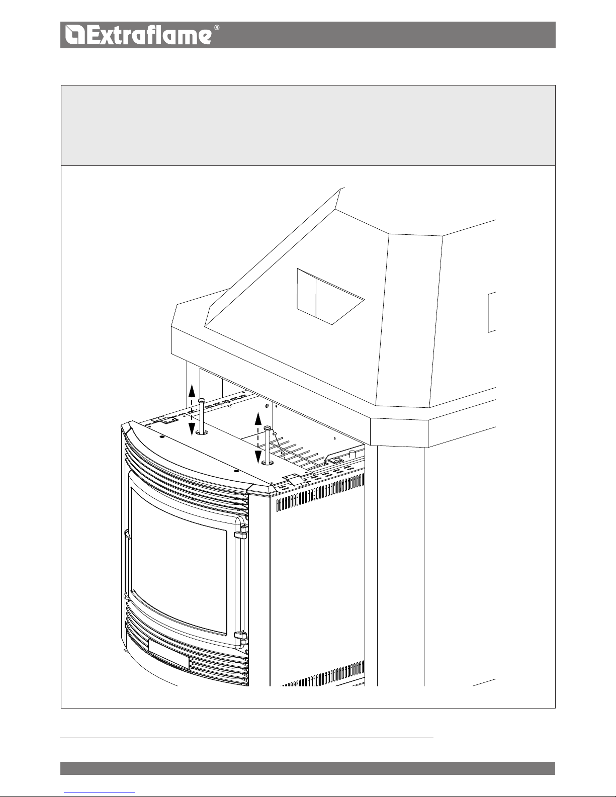
ENGLISH
SCRAPERS:
Use the scrapers, moving upwards (for models with upper scrapers) or pulling and pushing them (for the inserts and models
with front scrapers).
Please note: scrapers are preferably used when the stove is cold; if used when the stove is hot, it is recommended to
use special gloves to protect against the heat as they can get very hot.
DAILY
Open the door - Clean the glass with a damp cloth
Never spray the detergent or any other liquid used for cleaning directly on the ceramic glass
38
Page 39
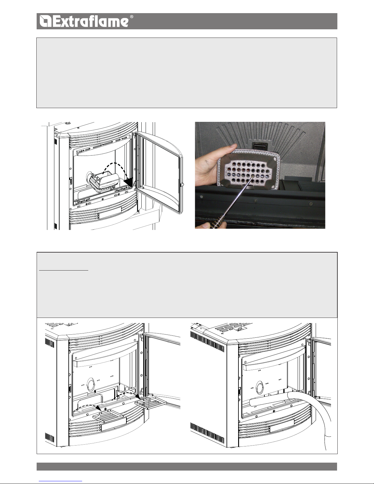
ENGLISH
EVERY 3/4 DAYS - WEEKLY
ASH DRAWER
Every 3-4 days check the ash drawer and empty it at least one/twice a week.
If there is a lower door, open/remove it.
Take out the removable ash drawer and empty it in a special container.
Vacuum the area underneath the removable ash drawer. Once you have cleaned it, place back the removable drawer and
close/place back the external door.
In some stoves the ash collector tray is located in the combustion chamber. In this case, just open the door and vacuum the
ash from the tray.
CLEANING THE BURN POT AND COMBUSTION CHAMBER
1. Vacuum the residues in the burn pot
2. Take out the burn pot from the designated compartment;
3. Vacuum the ash from the burn pot's seat and the combustion chamber (3.1)
4. Use the special poker supplied to clear the holes in the burn pot.
5. Place back the burn pot and push it towards the hearth wall.
6. If there is an ash collector tray, vacuum the ash deposits
PLEASE NOTE: USE A SUITABLE VACUUM CLEANER WITH A SPECIAL CONTAINER TO SEPARATE THE COLLECTED ASH.
39
Page 40

1
2
3
ENGLISH
CLEANING THE HEAT EXCHANGER (MONTHLY)
The heat exchangers chamber must be cleaned every month as the soot deposited on the rear of the cast iron hearth wall
blocks the regular ow of fumes.
To access the heat exchangers, remove the central piece from the hearth wall, following the operations described below:
Remove the brazier from its location
Manually rotate the 2 lockbolts, shown in gures 1 and 2, outwards.
Hold the extractable cast iron and pull it downwards.
Finally, slide it from the combustion chamber by pulling it towards yourself, paying attention to the 2 lateral cast iron hooks below.
Once the heat exchanger compartment can be accessed use the supplied re irons to remove and scrape the soot deposited
and only then use the suction device to completely remove the ash (gure 3). When cleaning has been completed, re-position
the extractable cast iron with the opposite movement used to remove it. When the hearth wall has been positioned, turn the
lockbolt to take it to its original position.
40
Page 41

F
A
D
C
C
A
E
D
B
ENGLISH
The images are for illustration purposes
ROUTINE MAINTENANCE CARRIED OUT BY AUTHORISED TECHNICIANS
Routine maintenance must be performed at least once a year.
As the generator uses pellets as solid fuel, it needs an annual routine maintenance interval that needs to be performed by an
authorised Technician by only using original spare parts.
Failure to do so can aect the appliance's safety and you may no longer be entitled to the warranty conditions.
By following the cleaning schedule reserved to the user and reported in the user and maintenance manual, one ensures correct
combustion in the generator over time, thereby preventing any anomalies and/or malfunctions that may require more work to
be performed by the technician. Requests for routine maintenance are not covered by the product's warranty.
DOOR, ASH DRAWER AND BURN POT GASKETS
The gaskets ensure the tightness of the stove and its consequent proper operation.
They must be checked periodically: in the event they are worn or damaged they must be replaced immediately.
These operations must be carried out by a qualied technician.
CONNECTION TO THE FLUE
Vacuum and clean the pipe that leads to the ue yearly or whenever necessary. If there are horizontal sections, any residue must
be removed before it obstructs the ue.
PUTTING THE EQUIPMENT OUT OF SERVICE (END OF THE SEASON)
At the end of every season, before turning o the stove, we recommend completely emptying the pellet tank and using a
vacuum cleaner to clear up any pellets and dust residue inside it.
You should also disconnect the generator from the mains and, to ensure greater safety especially if there are any children
around, remove the power supply cable.
Routine maintenance must be performed at least once a year.
IF THE POWER SUPPLY CABLE IS DAMAGED, IT MUST BE REPLACED BY THE AFTER-SALES SERVICE OR BY
A SIMILARLY QUALIFIED PERSON, SO AS TO AVOID ALL RISKS.
A
Fumes motor (disassembly and cleaning and fumes pipe), new silicone in required points
B
Inspection of gaskets, ash drawer and burn pot door (replace them and apply silicone where required)
C
Combustion chamber (total cleaning of the entire chamber) and ignition plug pipe cleaning
D
Tank (complete emptying and cleaning)
E
Room air fan disassembly and removal of dust and any pellet debris
F
Air intake pipe inspection and any ow sensor cleaning
41
Page 42
ENGLISH
DISPLAYS
DISPLAY REASON MEANING
START
The start phase is in progress _
PELLET FEEDING
the continuous feeding of the pellets
during the ignition phase is in
progress
_
IGNITION
The ignition phase is in progress
START-UP
The start-up phase is in progress _
BURN POT
CLEANING
The automatic burn pot cleaning is in
progress
_
FINAL CLEANING
The nal cleaning is in progress _
STAND-BY
COOLING
Start-up attempt while the stove is still
in cooling mode
Every time the stove displays one of the alarms listed above it will switch-
o automatically.
The alarm can only be released using button 1 when it switch-o has
been completed. The stove can only be switched back on when it
completely cold
WORK
The normal operating phase is in
progress, the stove is operating at the
set power
-
MODULATION
the stove is operating at minimum -
STAND - BY
Stove o waiting for re-ignition due
to an external thermostat
The stove will only re-start when the external thermostat will
request it
STDBY-BLACK OUT
The stove is cooling after a power cut. Once cooling is complete, it will automatically ignite
ROOM T
Displays room temperature (in the
models where provided)
-
HOFF
Stove o due to water temperature
over set
As soon as the water temperature drops below the set parameters,
the stove will switch back on
ANTI-FREEZE
The anti-freeze function is in progress
as the H2O t° is below the factory set
threshold
the pump is active until the water reaches the pre-set factory
parameter +2°C
ANTILOCK
The pump anti-locking function is in
progress (only if the stove has been in
O status for at least 96 hours)
the circulator is activated for the amount of time set by the
manufacturer to prevent it from locking
42
Page 43

ENGLISH
ALARMS
DISPLAY EXPLANATION SOLUTION
Indicates the presence of an alarm.
On: indicates the presence of an alarm
Flashing: indicates the deactivation of the depression
sensor.
The alarm can be reset by pressing key 1 for 3 seconds only
if the fumes motor has stopped and if 15 minutes have
passed from when the alarm was displayed.
ASPIRATION FAULT
Fumes motor fault Contact after-sales centre
FUMES PROBE
Fumes probe failure. Contact after-sales centre
HOT FUMES
High ue gas temperature
Verify pellet feed (see “Pellet feed regulation”). If the problem
cannot be solved, contact an authorised technician.
CLEAN CHECK UP 1 - 2
(1 = START-UP PHASE)
(2= WORK PHASE)
The door is not closed correctly.
The ash drawer is not closed correctly.
The combustion chamber is dirty.
The ue exhaust pipe is blocked.
Check hermetic door closure.
Check hermetic closure of the ash drawer.
Check cleanliness of the fumes pipe, of the sensor in the
primary air channel and the combustion chamber.
NO
IGNITION
The pellet feed-box is empty.
Pellet feed calibration inadequate.
Check for the presence of pellets in the feed-box.
Adjust pellet ow (see “Pellet feed adjustment”).
Check the procedures described in the “Ignition” chapter.
NO IGNITION
BLACK OUT
No current during the ignition phase.
Take the stove to OFF conditions using key 1 and repeat the
procedure described in the "Ignition" chapter.
NO PELLETS
The pellet feed-box is empty.
No pellet feed.
The motor reducer does not feed pellets.
Check for the presence of pellets in the feed-box.
Adjust pellet ow (see “Pellet feed adjustment”).
DEPR ALARM
The door is not closed correctly.
The ash drawer is not closed correctly.
The combustion chamber is dirty.
The ue exhaust pipe is blocked
Check hermetic door closure.
Check hermetic closure of the ash drawer.
Check cleanliness of the fumes pipe and the combustion
chamber.
DEBIMETER
FAULT
Faulty ow sensor.
Sensor disconnected
Contact after-sales centre
H20 OVERTEMPERA-
TURE
The water in the stove has exceeded 95°C.
Possible air in the system.
Insucient circulation.
No or inadequate safety zone.
Possible circulator anomaly.
Contact after-sales centre
MINIMUM PRESSURE
ALARM
The system pressure read by the pressure
switch is too low.
Possible presence of air in the system.
Possible lack of water or leaks due to
anomalies in some system component.
Contact after-sales centre
H2O PROBE ALARM
H2O probe failure
MAX H2O PRESSURE
ALARM
The pressure of the water has exceeded
the max threshold
Check that the expansion vessels are not damaged or
under-dimensioned
Check that the cold system is loaded at the correct pressure
43
Page 44

Extraame S.p.A. Via Dell’Artigianato, 12 36030 - MONTECCHIO PRECALCINO (VI) - ITALY
+39.0445.865911 - +39.0445.865912 - info@extraame.it - www.lanordica-extraame.com
004275824 - MU INSERTI PELLET COMFORT IDRO - 006
The Manufacturer reserves the right to vary the features and data shown in this booklet at any
time and without prior notice, in order to improve its products.
This manual cannot be considered as a contract for third parties.
 Loading...