

Page 1
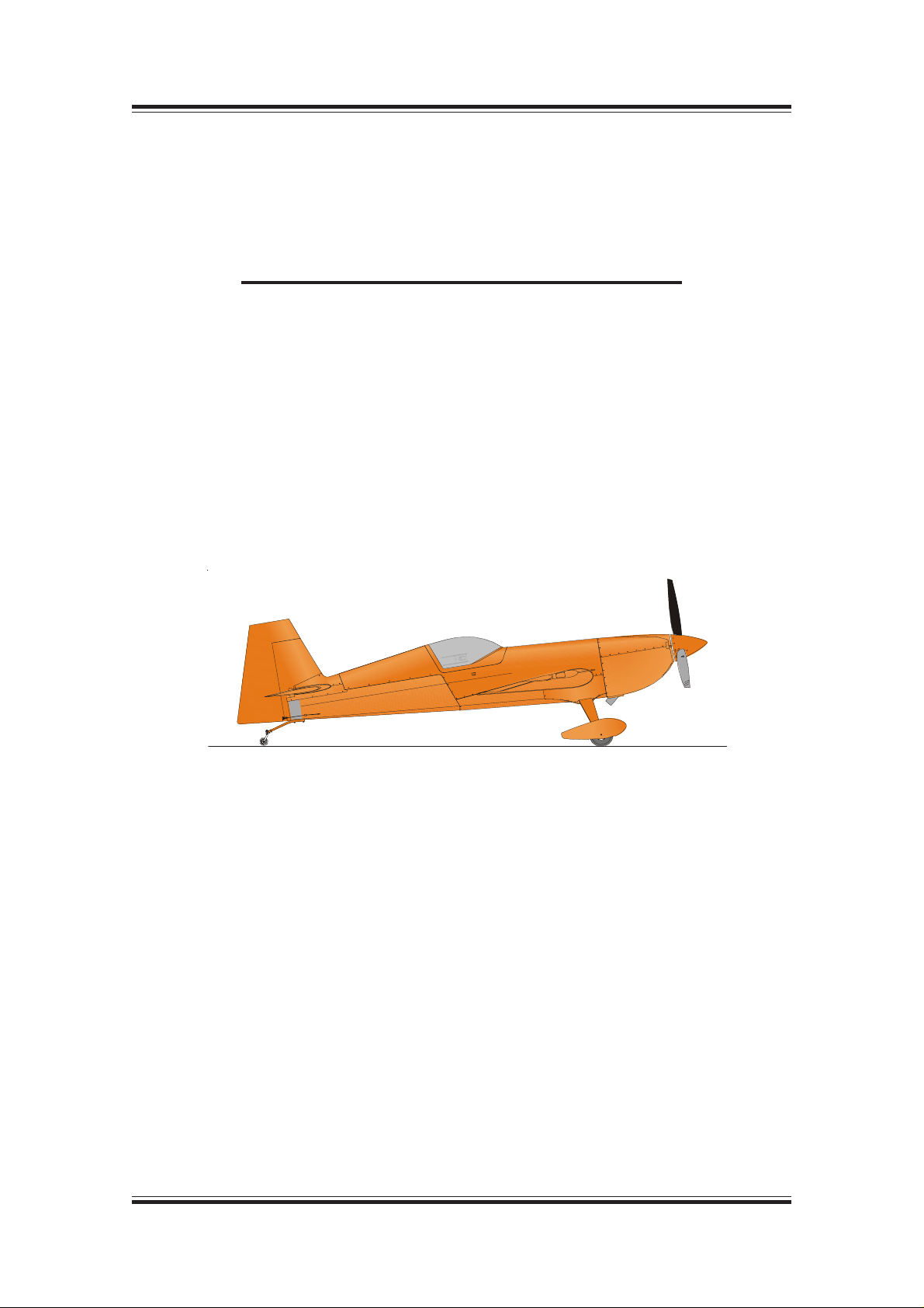
TITLE P AGE
I N F O R M A T I O N M A N U A L
E X T R A 3 0 0 / S C
MANUFACTURER
EXTRA Flugzeugproduktions- und Vertriebs- GmbH
Flugplatz Dinslaken
46569 Hünxe, Federal Republic of Germany
W A R N I N G
This is an Information Manual and may be used for general purposes only.
This Information Manual is not kept current.
It must not be used as a substitute for the official EASA Approved Pilot's Operating
Handbook required for operation of the airplane.
Page 2

Left blank intentionally
Page 3

Pilot´s Operating Handbook
EXTRA 300/SC
LOG OF REVISIONS
Dates of issue for original and revised pages:
Original ............................29. February 2008
Revision No. 1 .................. 12. February 2010
Revision No. 2 .....................10. August 2010
Revision No. 3 ................... 10. January 2011
EASA Approval No. and Date of approval:
EASA.A.C.08679 ....................17. July 2008
Approved under the authority of DOA
N° EASA.21J.073
Approved under the authority of DOA
N° EASA.21J.073
Approved under the authority of DOA
N° EASA.21J.073
Page Date: 10. January 2011
Page Date: 29. February 2008 i
Page 4

SECTION 0
LOG OF EFFECTIVE PAGES
Page Date
Title................................ 12. February 2010
i thru ii.............................. 10. January 2011
iii.................................... 29. February 2008
iv .................................... 12. February 2010
v..................................... 29. February 2008
vi .................................... 12. February 2010
0-1 thru 0-6 ..................................... deleted
1-1 thru 1-2 .................... 29. February 2008
1-3 thru 1-4 .................... 12. February 2010
1-5 thru 2-7 .................... 29. February 2008
2-4 ................................. 12. February 2010
2-5 thru 2-7 .................... 29. February 2008
2-8 ................................. 12. February 2010
2-9 thru 2-12................... 29. February 2008
2-13 .................................. 10. August 2010
2-14 thru 6-10................. 29. February 2008
6-11 thru 6-12................... 10. January 2011
7-1 thru 7-3 .................... 29. February 2008
7-4 ................................. 12. February 2010
7-5 ................................. 29. February 2008
7-6 thru 7-7 ...................... 10. January 2011
7-8 thru 7-10................... 29. February 2008
7-11 ............................... 12. February 2010
7-12 thru 7-14................... 10. January 2011
7-15 thru 8-4................... 29. February 2008
9-1 ................................. 12. February 2010
9-2 thru 907-4................. 29. February 2008
908-1 thru 909-4 ............. 12. February 2010
Pilot´s Operating Handbook
EXTRA 300/SC
Page Date
ii Page Date: 29. February 2008
Page Date: 10. January 2011
Page 5

Pilot´s Operating Handbook
EXTRA 300/SC
Left blank intentionally
Page Date: 29. February 2008 iii
Page 6

INTRODUCTION
This handbook contains 9 sections, and includes the material required to be furnished to the pilot
by FAR-23. It also contains supplementary data supplied by EXTRA Flugzeugproduktions- und
Vertriebs- GmbH.
THIS MANUAL IS FURNISHED TO THE CIVIL AVIATION AUTHORITIES AS A PART OF THE
CERTIFICATION MATERIAL FOR THIS MODEL.
NOTES
This Flight Manual applies only to the aircraft whose nationality and registration marks are noted
on the title page.
This Flight Manual is only valid in connection with the latest, new EASA approved revision. Refer
to the EXTRA Homepage (direct link: http://www.extraaircraft.com/techserv.asp), where the
POH Revision Index always shows the current revision status.
It is the responsibility of the pilot to be familiar with the contents of this Flight Manual
including revisions and any relevant supplements.
Pilot´s Operating Handbook
EXTRA 300/SC
Pages of this Airplane Flight Manual must not be exchanged and no alterations of or additions
to the approved contents may be made without the EXTRA Flugzeugproduktions- und VertriebsGmbH/EASA approval.
The editor has the copyright of this Flight Manual and is responsible for edition of revisions/
amendments and supplements.
Amendments, which affect the airworthiness of the aircraft will be announced in the mandatory
Service Bulletins issued by the manufacturer EXTRA Flugzeugproduktions- und Vertriebs- GmbH
coming along with the "Airworthiness Directive" (AD) publication issued by the EASA. The owner
is responsible for incorporating prescribed amendments and should make notes about these on
the records of amendments.
Should this Flight Manual get lost, inform EXTRA Flugzeugproduktions- und Vertriebs- GmbH,
Flugplatz Dinslaken 46569 Hünxe, Federal Republic of Germany.
Should this Flight Manual be found, kindly forward it to the civil board of aviation in the country
the aircraft is registered.
iv Page Date: 29. February 2008
Page Date: 12. February 2010
Page 7

Pilot´s Operating Handbook
EXTRA 300/SC
WARNINGS, CAUTIONS AND NOTES
The following definitions apply to Warnings, Cautions, and Notes:
=> Operating procedures, techniques, etc., which could result in personal
injury or loss of life if not carefully followed.
=> Operating procedures, techniques, etc., which could result in damage to
equipment if not carefully followed.
WARNING
CAUTION
NOTE
=> An operating procedures, technique, etc., which is considered essential
to emphasize.
"Shall, "Will", "Should" and "May"
The words "shall" or "will" shall be used to express a mandatory
requirement The word "should" shall be used to express nonmandatory
provisions The word "may" shall be used to express permissible.
Page Date: 29. February 2008 v
Page 8

Pilot´s Operating Handbook
EXTRA 300/SC
MAIN TABLE OF CONTENTS
Section Page
1 GENERAL 1-1
2 LIMITATIONS 2-1
3 EMERGENCY PROCEDURES 3-1
4 NORMAL PROCEDURES 4-1
5 PERFORMANCE 5-1
6 WEIGHT & BALANCE/EQUIPMENT LIST 6- 1
7 AIRPLANE & SYSTEMS DESCRIPTIONS 7- 1
8 AIRPLANE HANDLING, SERVICE & MAINTENANCE 8- 1
9 SUPPLEMENTS 9-1
vi Page Date: 29. February 2008
Page Date: 12. February 2010
Page 9

Pilot´s Operating Handbook
EXTRA 300/SC
Section 1
General
SECTION 1
GENERAL
Table of Contents
Paragraph Page
SECTION 1 GENERAL
1.0 DESCRIPTION.................................................................................................................... 1-3
1.1 SPECIFICA TION OF CLASS .............................................................................................. 1-3
1.2 MANUFACTURER .............................................................................................................. 1-3
1.3 TECHNICAL DATA.............................................................................................................. 1-3
1.3.1 3-View Drawing ................................................................................................................... 1-3
1.3.2 Main Data............................................................................................................................ 1-4
1.3.3 Wing.................................................................................................................................... 1-4
1.3.4 Horizontal Tail ...................................................................................................................... 1-4
1.3.5 Elevator ............................................................................................................................... 1-4
1.3.6 Vertical Tail .......................................................................................................................... 1-4
1.3.7 Rudder ................................................................................................................................ 1-4
1.4 ENGINE .............................................................................................................................. 1-4
1.5 PROPELLER ...................................................................................................................... 1-5
1.5.1 Exhaust System .................................................................................................................. 1-5
1.6 FUEL................................................................................................................................... 1-5
1.7 OIL ...................................................................................................................................... 1-5
1.8 LOADING............................................................................................................................ 1-6
1.9 TERMINOLOGY ................................................................................................................. 1-6
1.10 SECONDARY TERMINOLOGY .......................................................................................... 1-7
1.11 CONVERSION TABLE ....................................................................................................... 1-8
Page Date: 29. February 2008 1 - 1
Page 10

Section 1
General
Pilot´s Operating Handbook
EXTRA 300/SC
Left blank intentionally
1 - 2 Page Date: 29. February 2008
Page 11
Pilot´s Operating Handbook
EXTRA 300/SC
1.0 DESCRIPTION
The airframe of the EXTRA 300/SC is built of a tig-welded steel-tube construction. Wing,
empennage and landing gear are manufactured of composite material. The aircraft is a single
seater.
1.1 SPECIFICATION OF CLASS
The aircraft is certified in normal and acrobatic category.
EASA - Approval No.: EASA.A.C.08679
1.2 MANUFACTURER
EXTRA Flugzeugproduktions- und Vertriebs- GmbH,
Flugplatz Dinslaken
46569 Hünxe,
Federal Republic of Germany.
Section 1
General
1.3 TECHNICAL DATA
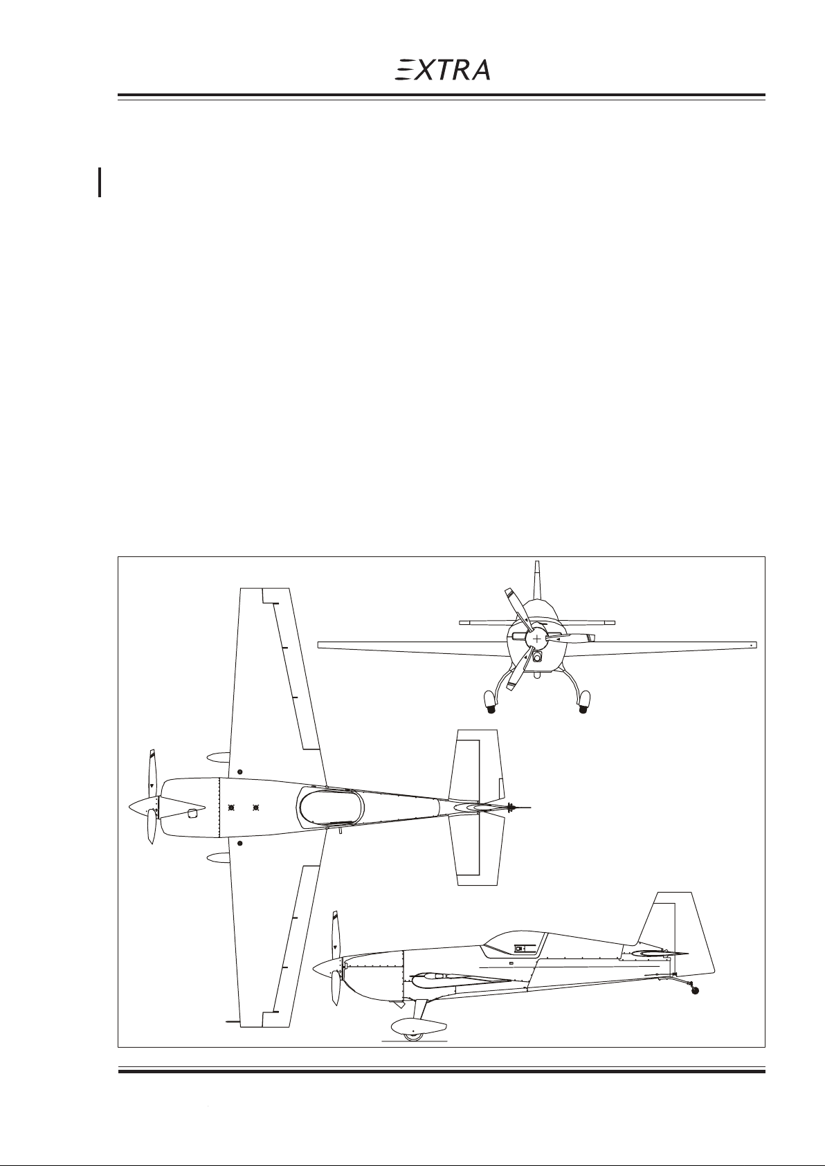
1.3.1 3-View Drawing
Page Date: 29. February 2008 1 - 3
Page Date: 12. February 2010
Page 12

Section 1
General
1.3.2 Main Data
- Length 6.88 m (22.57 ft)
- Height 2.55 m (8.36 ft)
- Span 7.50 m (24.61 ft)
- Wheel-base 1.80 m (5.91 ft)
- Wheel-track 4.87 m (15.98 ft)
1.3.3 Wing
- Wing span 7.50 m (24.61 ft)
- Wing-area 9.81 m² (105.6 ft²)
- Airfoil Root: MA 14.9 S
- Chord Root: 1.786 m (5.86 ft)
- MAC 1.366 m (4.48 ft)
- Aileron area 2 x 0.876 m² (2x 9.429 ft²)
- Aileron deflection up/down 30°, tolerance ±2°
Pilot´s Operating Handbook
EXTRA 300/SC
Tip: MA 12 S
Tip: 0.830 m (2.72 ft)
1.3.4 Horizontal Tail
- Span 2.66 m (8.73 ft)
- Area 2.13 m² (22.92 ft²)
- Airfoil NACA 0009
1.3.5 Elevator
- Area 1.04 m² (11.19 ft²)
- Elevator-deflection up/down 25°; tolerance ±1°
- Trim-tab-deflection up/down 32°, tolerance ±2°
1.3.6 Vertical Tail
- Area 1.55 m² (16.68 ft²)
- Airfoil Wortmann FX 71-L-150/30
1.3.7 Rudder
- Area 0.75 m² (8.07 ft²)
- Rudder deflection left/right 30°, tolerance +0°/-2°
1.4 ENGINE
Manufacturer Textron-Lycoming Williamsport Plant PA 17701 USA.
Type: Lycoming AEIO-580-B1A
Rated power: 234.9 kW (315 HP)
1 - 4 Page Date: 29. February 2008
Page Date: 12. February 2010
Page 13

Pilot´s Operating Handbook
EXTRA 300/SC
1.5 PROPELLER
Manufacturer MT-Propeller Entwicklung GmbH, Federal Republic of Germany.
Type: MTV-9-B-C/C198-25 3-blade constant speed
1.5.1 Exhaust System
Standard: Complete 6 in 1 system with integrated silencer.
Manufacturer: Gomolzig Flugzeug- und Maschinenbau, West Germany
Option: Complete 6 in 1 System, stainless steel
Manufacturer: Sky Dynamics Corporation, Moneta, USA
1.6 FUEL
Type: AVGAS 100/100 LL
(for alt. fuel grades see latest issues of Textron Lyc. S.I. No 1070)
Minimum 100/130 octane. Maximum 100/130 octane
- Total fuel volume 224 L (59.2 US Gallon)
- Front center tank 54 L (14.3 US Gallon)
- Rear center tank 41 L (10.8 US Gallon)
- Acro tank 9 L ( 2.4 US Gallon)
- Wing tank 120 L (31.7 US Gallon)
- Usable fuel in the system 221 L (58.4 US Gallon)
- Usable fuel for acrobatic
(acro and center tanks) 101 L (26.7 US Gallon)
Section 1
General
1.7 OIL
Maximum sump capacity: 16 qts.
Minimum sump capacity: 9 qts.
Average ambient air Mil-L6082 Mil-22851
temperature grades ashless dispersant grades
All temperatures ---- SAE 15W50 or 20W50
> 27°C (80°F) SAE 60 SAE 60
> 16°C (60°F) SAE 50 SAE 40 or 60
- 1°C til 32°C SAE 40 SAE 40
(30°F - 90°F)
- 18°C til 21°C SAE 30 SAE 30,40 or 20W40
(0°F - 70°F)
- 18°C til 32°C SAE 20W50 SAE 20W50 or 15W50
(0°F - 90°F)
< -12°C (10°F) SAE 20 SAE 30 or 20W30
(single or multi - viscosity aviation grade oils see latest issue of Textron Lyc. S.I. No. 1014)
Page Date: 29. February 2008 1 - 5
Page Date: 29. February 2008
Page 14

Section 1
General
1.8 LOADING
Wing loading (Acrobatic Cat.) 79.50 kg/m² (16.29 lbs./sqf)
Power loading (Acrobatic Cat.) 3.32 kg/kW (5.46 lbs./HP)
1.9 TERMINOLOGY
Air Speeds
CAS Calibrated air speed. CAS is the same as TAS
KCAS Calibrated speed in knots
GS Ground speed
Pilot´s Operating Handbook
EXTRA 300/SC
(Normal Cat.) 88.68 kg/m² (18.17 lbs./sqf)
(Normal Cat.) 3.70 kg/kW (6.09 lbs./HP)
(True Air Speed) in std. atmospheric condition at sea level
IAS Indicated air speed
KIAS Indicated speed in knots
TAS True air speed. Is equal to CAS compensated for
altitude, temperature and density
V
A
V
NE
V
NO
V
S
V
X
V
Y
Maneuvering speed
Never exceed speed
Maximum structural crusing speed
Stalling speed or minimum steady flight speed
Best angle-of-climb speed
Best rate-of-climb speed
Meteorological terminology
ISA International standard atmospheric condition
OAT Outside air temperature
1 - 6 Page Date: 29. February 2008
Page 15

Pilot´s Operating Handbook
EXTRA 300/SC
1.10 SECONDARY TERMINOLOGY
fpm Feet/minute
ft Feet = 0.3048 m
in inch = 2,54 cm
m Meter
L Litres
gal US gallon = 3.79 litres
qts US quart = 0.946 litres
hp Horse power (english)
h Hour
kts Knots (NM/h) = 1.852 kilometer per hour
Section 1
General
km/h kilometer per hour
lbs English pound = 0.4536 kg
hPa hekto Pascal
inHg Inches of mercury
MP Manifold pressure
PA Pressure altitude (ft)
nm Nautical miles = 1.852 km
rpm Revolutions per minute
CG Center of gravity
Arm Arm is the horizontal distance from reference datum
Moment Weight of an item multiplied by its arm.
Page Date: 29. February 2008 1 - 7
Page 16
Section 1
General
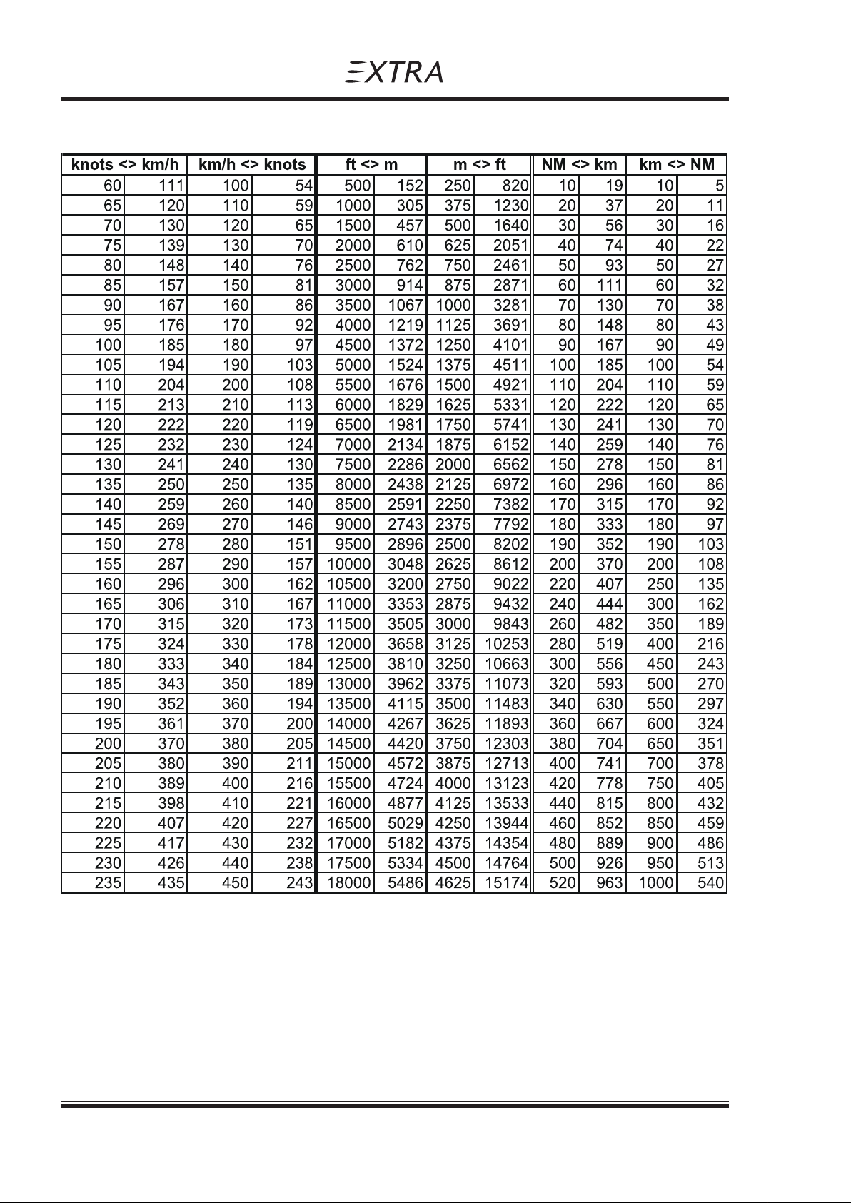
1.11 CONVERSION TABLE
Pilot´s Operating Handbook
EXTRA 300/SC
1 - 8 Page Date: 29. February 2008
Page 17

Pilot´s Operating Handbook
EXTRA 300/SC
Section 2
Limitations
SECTION 2
LIMITATIONS
Table of Contents
Paragraph Page
SECTION 2 LIMIT A TIONS
2.1 GENERAL ........................................................................................................................... 2-3
2.2 AIR SPEED (IAS) ................................................................................................................ 2-3
2.3 CROSS-WIND COMPONENT............................................................................................. 2-3
2.4 ENGINE .............................................................................................................................. 2-3
2.4.1 Fuel ..................................................................................................................................... 2-4
2.4.2 Engine Limitations ............................................................................................................... 2-4
2.5 PROPELLER ...................................................................................................................... 2-5
2.6 WEIGHT LIMITS................................................................................................................. 2-5
2.7 WEIGHT AND C.G . ENVELOPE ......................................................................................... 2-5
2.7.1 Normal Flight....................................................................................................................... 2-5
2.7.2 Acrobatic Flight.................................................................................................................... 2-5
2.8 ACROBA TIC MANEUVERS................................................................................................ 2-5
2.8.1 Normal Flight....................................................................................................................... 2-5
2.8.2 Acrobatic Flight.................................................................................................................... 2-6
2.9 LOAD F ACTOR................................................................................................................... 2-7
2.9.1 Normal Flight....................................................................................................................... 2-7
2.9.2 Acrobatic Flight.................................................................................................................... 2-7
2.10 KINDS OF OPERATIONAL LIMITS .................................................................................... 2-7
2.11 STRUCTUAL TEMPERA TURE/COLOUR LIMITATION...................................................... 2-7
2.12 MAXIMUM OPERA TING AL TITUDE................................................................................... 2-7
2.13 TIRE PRESSURE ............................................................................................................... 2-7
2.14 MARKINGS AND PLACARDS ............................................................................................ 2-7
2.14.1 Aircraft Identity Placard ....................................................................................................... 2-7
2.14.2 Operating Placards.............................................................................................................. 2-8
2.14.3 Instrument Markings.......................................................................................................... 2-13
2.15 KINDS OF OPERA TION EQUIPMENT LIST.....................................................................2-14
2.16 NOISE LEVEL................................................................................................................... 2-15
Page Date: 29. February 2008 2 - 1
Page 18

Section 2
Limitations
Pilot´s Operating Handbook
EXTRA 300/SC
Left blank intentionally
2 - 2 Page Date: 29. February 2008
Page 19

Pilot´s Operating Handbook
EXTRA 300/SC
2.1 GENERAL
This section includes operating limitations, instrument markings, and basic placards
necessary for the safe operation of the aircraft, its engine, standard systems, and standard
equipment. The limitations included in this section have been approved by the EASA.
Observance of these operating limitations is required by national aviation regulations.
In case of the EXTRA 300/SC is equipped with specific options additional information
required for safe operation will be contained in Section 9 "Supplements".
Section 2
Limitations
SECTION 2
LIMITATIONS
NOTE
EASA Approcal No.: EASA.A.C.08679
Any exceedance of given limitations have to be reported by the pilot and considered by
corresponding maintenance or inspection procedure according to MAINTENANCE MANUAL
EXTRA 300/SC.
2.2 AIR SPEED (IAS)
Never Exceed Speed V
Max. Structural Cruising Speed V
Maneuver speed (Acrobatic Cat.) V
(Normal Cat.) V
2.3 CROSS-WIND COMPONENT
Max. demonstrated cross-wind component for take-off and landing is 15 knots (27 km/h).
2.4 ENGINE
Engine-type Textron-Lycoming Lycoming AEIO-580-B1A with rated maximum 315 HP @
2700 RPM.
219 knots (406 km/h)
NE
154 knots (285 km/h)
NO
154 knots (285 km/h)
A
138 knots (256 km/h)
A
Page Date: 29. February 2008 2 - 3
Page 20
Section 2
Limitations
2.4.1 FUEL
Minimum grade aviation gasoline: 100/100LL for alternate fuelgrades see latest revision of
Lyc. S.I. No. 1070.
Total fuel capacity 224 L (59.2 US Gallon).
Usable fuel capacity 221 L (58.4 US Gallon).
Acrobatic flight only with center tanks.
Total fuel capacity for acrobatic (acro & center tanks) 104 L (27.5 US Gallon).
Usable fuel capacity for acrobatic (acro & center tanks) 101 L (26.7 US Gallon).
2.4.2 ENGINE LIMITATIONS
a) RPM
- Max. Take-Off 2700 RPM
- Max. Continuous 2700 RPM
b) Oil temperature
- Max 118°C 245°F
c) Oil capacity
- Maximum sump capacity: 16 qts.
- Minimum sump capacity: 9 qts.
Pilot´s Operating Handbook
EXTRA 300/SC
d) Oil pressure
- Minimum Idling 172 kPa 25 psig
- Normal 379 - 655 kPa 55 - 95 psig
- Starting, Warm up
Taxi and Take-Off 793 kPa 115 psig
C A U T I O N
It is normal for the oil pressure to "flicker" from 10 to 30 psi (69 to 207 kPa) when going from
upright to inverted flight. During knife edge flights and zero-g flights oil pressure may drop
and the oil system may not scavenge resulting in engine failure or damage if flight is
prolonged. Knife edge and zero-g flight should not exceed 10 seconds.
W A R N I N G
If oil pressure drops to 0 psi (kPa) the propeller pitch changes automatically to coarse (high)
pitch with a corresponding decrease in RPM. Apply positive g to avoid engine stoppage.
e) Fuel pressure at inlet to fuel injector
- Max 65 psig
- Min 29 psig
- Min Idle 12 psig
f) Cylinder head temperature
- Max 241°C 465°F
2 - 4 Page Date: 29. February 2008
Page Date: 12. February 2010
Page 21

Pilot´s Operating Handbook
EXTRA 300/SC
2.5 PROPELLER
MT-Propeller Entwicklung GmbH, Federal Republic of Germany
Type: MTV-9-B-C/C198-25 3-blade constant speed
Max. allowed rotational speed (Take-Off and Continuous):
- Acrobatic category 2700 RPM
- Normal category 2600 RPM
2.6 WEIGHT LIMITS
Max. allowed empty weight:
- Acrobatic category 620 kg (1367 lbs)
- Normal category 624 kg (1376 lbs)
Max. allowed T/O weight:
- Acrobatic category 780 kg (1720 lbs)
- Normal category 870 kg (1918 lbs)
Max allowed landing weight:
- Acrobatic category 780 kg (1720 lbs)
- Normal category 870 kg (1918 lbs)
Section 2
Limitations
2.7 WEIGHT AND C.G. ENVELOPE
Vertical reference = fire-wall.
Horizontal reference = upper longerons in cockpit.
2.7.1 NORMAL FLIGHT
forward C.G. rear C.G.
820 kg (1808 lbs) 780 kg (1720 lbs)
or below: 53.7 cm (21.1") or below: 66.8 cm (26.3")
870 kg (1918 lbs): 54.5 cm (21.5") 870 kg (1918 lbs): 62.6 cm (24.6")
Straight line variation between points.
2.7.2 ACROBATIC FLIGHT
forward C.G. rear C.G.
780 kg (1720 lbs) 780 kg (1720 lbs)
or below: 53.7 cm (21.1") or below: 66.8 cm (26.3")
2.8 ACROBATIC MANEUVERS
2.8.1 NORMAL FLIGHT
All acrobatic maneuvers are prohibited except stall, chandelle, lazy eight and turns up to
60 degrees bank angle.
Page Date: 29. February 2008 2 - 5
Page 22
Section 2
Limitations
Pilot´s Operating Handbook
2.8.2 ACROBATIC FLIGHT
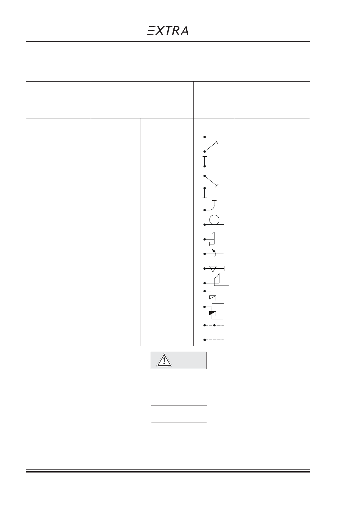
The plane is designed for acrobatics. Inverted flight maneuvers are limited to max 4 min.
Recommended basic maneuver entry speeds are listed in the following list:
Recommended entry
Maneuvers speeds (IAS) Symbol Remarks
min knots (km/h) max knots (km/h)
Segment:
Horizontal Line V
S
V
NE
EXTRA 300/SC
45°climbing 80 (148) V
90° up V
45° diving V
90° diving V
A
S
S
NE
V
NE
V
NE
V
NE
reduce throttle
reduce throttle
1/4 Loop climb. 100 (185) 190 (352)
Looping 100 (185) 190 (352)
Stall turn 100 (185) 190 (352)
Aileron roll 80 (148) V
A
full deflection
Snap roll 80 (148) 140 (259)
"Tail slide" 100 (185) 190 (352)
Spin V
Inverted spin V
S
S
Knife edge >150 (278) < 10 s
Inverted Flight >V
S
190 (352) < 4 min
CAUTION
Particular caution must be exercised when performing maneuvers at speeds above
VA [154 KIAS (285 km/h)]. Large or abrupt control inputs above this speed may impose
unacceptably high loads which exceed the structural capability of the aircraft.
N O T E
For Acrobatic Maneuvers see Section 4. All maneuvers can be performed in positive and
negative flight attitude.
2 - 6 Page Date: 29. February 2008
Page 23

Pilot´s Operating Handbook
EXTRA 300/SC
2.9 LOAD FACTOR
2.9.1 NORMAL FLIGHT
Normal Cat.: + 6 g / - 3 g for MTOW 870 kg (1918 lbs)
2.9.2 ACROBATIC FLIGHT
Acro Cat.: + 10 g / - 10 g for MTOW 780 kg (1720 lbs)
2.10 KINDS OF OPERATIONAL LIMITS
Only VFR flights at day are allowed. The A/C may be operated at OAT from -20°C (-4°F) to
+38°C (100°F). Flight in known icing-conditions is prohibited. Flights close to thunderstorms
are prohibited. Smoking is prohibited.
Section 2
Limitations
2.11 STRUCTUAL TEMPERATURE/COLOUR LIMITATION
Structure is qualified up to 72°C (161,6°F). Structure temperatures (composite) above 72°C
(161,6°F) are not permitted. In order not to exceed this temperature limit, color specification
for composite structure (manufacturer document EA-03205.19) has to be complied with.
2.12 MAXIMUM OPERATING ALTITUDE
Max. certified operating altitude is 10,000 ft MSL (3048 m).
2.13 TIRE PRESSURE
The tire pressure is 2620 hpa (38 psi).
2.14 MARKINGS AND PLACARDS
2.14.1 AIRCRAFT IDENTITY PLACARD
EXTRA
FLUGZEUGPRODUKTIONSUND VERTRIEBS-GMBH
MODEL: EXTRA 300/SC
SERIAL NUMBER:
TC-NUMBER: *
*/**
*)The latest national aviation regulations must be observed in determining whether the
placard is required.
**) call sign placard
Page Date: 29. February 2008 2 - 7
Page 24

Section 2
Limitations
2.14.2 OPERATING PLACARDS
Pilot´s Operating Handbook
EXTRA 300/SC
V = 154 KTS (ACRO)
A
V = 138 KTS (NORMAL)
A
or
V = 285 km/h (ACRO)
A
V = 256 km/h ( NORMAL )
A
(near the airspeed indicator)
The markings and placards installed in this airplane contain
operating limitations which must be complied with when operating
this airplane in the acroba tic category . Other limit ations which must
be comp lied wi th whe n opera ting th is air plane in this c ategor y or in
the normal category are cont ained in the airplane flight manual.
(in the cockpit)
This airplane is certified for VFR day
operati on. Operation un der known
icing conditions or close t o
thunder storms is prohibit ed.
(on the instrument panel)
F U E L
AVGAS 100/100LL
(near each filler cap)
OIL
(on the seperate hatch / upper cowling)
ELEV. TRIM
DOWN
(Next to the trim switch)
UP
(Next to the trim switch)
TRIM
DOWN
UP
(On the instrument panel on the trim LED indicator)
2 - 8 Page Date: 29. February 2008
Page Date: 12. February 2010
Page 25
Pilot´s Operating Handbook
EXTRA 300/SC
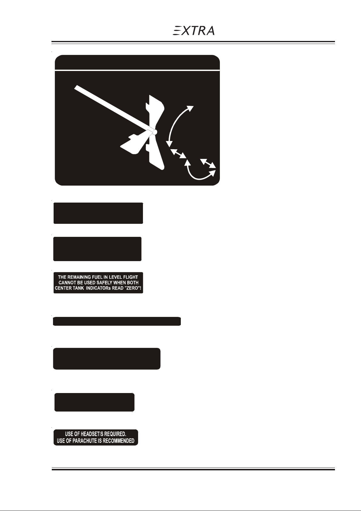
FUEL SELECTOR VALVE
120 L usable (31.7 US GAL)
ACRO
&
CENTER
TANKS
101 L usable
(26.7 US GAL)
(in cockpit next to fuel selector)
Section 2
Limitations
WING TANK
OFF
MUST BE EMPTY FOR ACROBATICS.
USABLE FU EL 120L (31. 7 U S GAL).
(On the instrument panel beneath wing tank fuel capacity indicator)
CENTER TANK INDICA T ION
SHOWS "ZERO" IN LEVEL FLIGHT
UNUSABLE FUEL 3 L (0.8 US GAL).
(On the instrument panel beneath center tank fuel capacity indicator)
(On the instrument panel beneath the acro & center tanks fuel capacity indicators)
ACROBATIC: +10G / -10G MTOW 780KG (1720LBS)
(In cockpit)
NORMAL : 6G / -3G MT O W 870KG (1918LBS)
(In cockpit)
WING TANK
BELOW 9 L (2.37 US GAL).
ACROBATICS INCL. SPIN
NOT APPROVED!
NO SMOKING
(In cockpit)
(On the right side of instrument panel)
Page Date: 29. February 2008 2 - 9
Page 26
Section 2
Limitations
Pilot´s Operating Handbook
EXTRA 300/SC
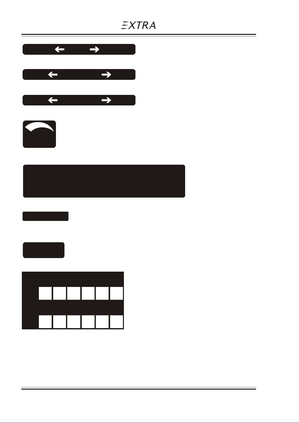
LOW RPM
(On RPM control in the cockpit)
RICH
(On mixture control in the cockpit)
CLOSE
(Near throttle control in the cockpit)
PROP HIGH RPM
MIXTURE LEAN
THROTTLE OPEN
VENT
OPEN
(Near the eyeball-type adjustable vents)
CAUTION
Particular caution must be exercised whe n performing maneuvers
at speeds above V . Large or abrupt control inputs above this speed
may impose unacceptably h igh loads which exce ed the stru ctural
capability of the aircraft.
A
(In cockpit)
NO
EA 300/ SC
(In cockpit)
CALLSIGN
(In cockpit)
For
N 030 060 E 120 150
Steer
For
S 210 240 W 300 330
Steer
(Near Mag. Dir. Indicator)
2 - 10 Page Date: 29. February 2008
Page 27

Pilot´s Operating Handbook
EXTRA 300/SC
WING TANK DRAIN
(Near the LH drain valve in the bottom fuselage cover)
CENTER TANK DRAI N
(Near the RH drain valve in the bottom fuselage cover)
GASCOLATOR DRAIN
(Near the drain valve on the RH lower side of the firewall)
USE STRAIGHT MINERAL OIL
FOR A MINIMUM OF 50 HOURS
(On the inside of the separate hatch / upper cowling)
Section 2
Limitations
2.6 BAR
38 PSI
(On the outside of the wheelpants)
TORQUE TUBE
LUBRICATIO N
(Near opening in middle of bottom fuselage cover)
/ / / / / / / / NO STEP! \ \ \ \ \ \ \ \
(In the cockpit, on the aileron control rods)
M
I
C
R
O
P
H
O
N
E
S
(In cockpit, on the RH side)
Page Date: 29. February 2008 2 - 11
Page 28

Section 2
Limitations
Pilot´s Operating Handbook
Approved acrobatic maneuvers and recommended entry airspeeds
Maneuvers Airspeeds Maneuvers Airspeeds
min KIAS max KIAS min KIAS max KIAS
Segment:
EXTRA 300/SC
Horizontal Line V V Aileron roll 80
45°climbing 80 V Snap roll 80 140
90° up V V "T ail-slide" 100 190
45° diving V V Spin V ----
90° diving V V Inverted spin V ---1/4 Loop climb. 100 190 Inverted flight > V 190
SNE
NE
ANE
SNE S
SNE S
(Less than 4 min)
S
V
A
Loop 100 190
Knife edge >150 ----
Stall turn 100 190 (Less than 10 s)
or
Approved acrobatic maneuvers and recommended entry airspeeds
Maneuvers Airspeeds Maneuvers Airspeeds
min max min max
Segment:
Horizontal Line V V Aileron roll 148
45°climbing 148 km/h V Snap roll 148 259
90° up V "Tail-slide" 185 352
45° diving V V Spin V ----
90° diving V V Inverted spin V ---1/4 Loop climb. 185 352 Inverted flight > V 352
SNE
NE
V km/h km/h
A
SNE S
SNE S
NE
km/h km/h km/h
(Less than 4 min)
Loop 185 352
km/h km/h
Knife edge >278 ----
Stall turn 185 352 (Less than 10 s)
km/h km/h
km/h V
A
km/h km/h
S
km/h
(In cockpit)
2 - 12 Page Date: 29. February 2008
Page 29

Pilot´s Operating Handbook
EXTRA 300/SC
2.14.3 INSTRUMENT MARKINGS
AIRSPEED INDICATOR
green arc 64 KIAS (119 km/h) - 154 KIAS (285 km/h)
yellow arc 154 KIAS (285 km/h) - 219 KIAS (406 km/h)
red line 219 KIAS (406 km/h)
OIL PRESSURE INDICATOR
Section 2
Limitations
NOTE
Oil pressure indicator shows psig values even when labelled 'Psi'.
Range markings depending on instrument installed.
red line 25 psig
yellow arc 25 psig - 55 psig
green arc 55 psig - 95 psig or 55 psig - 90 psig
yellow arc 95 psig - 115 psig o r 90 psig - 100 psig
red line 115 psig or 100 psig
OIL TEMPERATURE INDICATOR
yellow arc < 140 °F
green arc 140 °F - 210 °F
yellow arc 210 °F - 245 °F
red line 245°F
CYLINDERHEAD TEMPERATURE INDICATOR
yellow arc < 150 °F
green arc 150 °F - 435 °F
yellow arc 435 °F - 465 °F
red line 465 °F
RPM INDICATOR
green arc 700 RPM - 2700 RPM
yellow arc 2400 RPM - 2700 RPM
red line 2700 RPM
FUEL FLOW INDICATOR
green arc 0 gal / h - 35 gal / h
red radial 35 gal / h
MANIFOLD PRESSURE INDICATOR
green arc 10 " Hg - 25 " Hg
yellow arc 25 " Hg - 29.5 " Hg
red radial 29.5 " Hg
Page Date: 10. August 2010
Page Date: 29. February 2008 2 - 13
Page 30

Section 2
Limitations
2.15 KINDS OF OPERATION EQUIPMENT LIST
The aircraft may be operated in day-VFR when the appropriate equipment is installed and
operable. Flying under known icing conditions and close to thunderstorms are prohibited.
The following equipment list identifies the systems and equipment upon which certification
was predicated.
The following systems and items of equipment must be installed and operable for the
particular kind of operation indicated.
COMMUNICATION
1. Transceiver-VHF 1 1
ELECTRICAL POWER
1. Battery 1 1
2. Alternator 1 1
3. Ampermeter 1 1
Pilot´s Operating Handbook
EXTRA 300/SC
NORMAL ACROBATIC
FLIGHT CONTROL SYSTEM
1. Elevator-trim control (electric) 1 1
FUEL
1. Boost pump 1 1
2. Fuel quantity indicator (front center tank) 1 1
3. Fuel quantity indicator (rear center tank) 1 1
4. Fuel quantity indicator (wing tank) 1 1
5. Manifold pressure 1 1
6. Fuel flow indicator 1 1
7. Fuel pressure 0 0
LIGHT
1. Wing-tip position/strobe light * *
NAVIGATION
1. Altimeter 1 1
2. Airspeed indicator 1 1
3. Mag. direction indicator 1 1
4. Transponder
1
11
1
) In some airspaces Mode S Elementary Surveillance functionality is required
2 - 14 Page Date: 29. February 2008
Page 31
Pilot´s Operating Handbook
EXTRA 300/SC
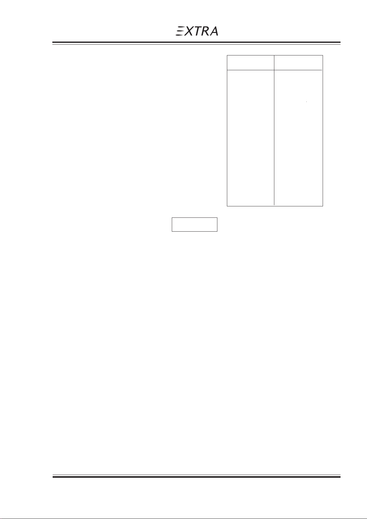
ENGINE CONTROL
1. RPM indicator 1 1
2. Exhaust gas temperature ind. 0 0
3. Cylinder head temperature ind. 0 0
OIL
1. Oil temperature indicator 1 1
2. Oil pressure indicator 1 1
FLIGHT CREW EQUIPMENT
1. Parachute 0 */**
2. Seat belt 1 1
3. Headset 1 1
Section 2
Limitations
NORMAL ACROBATIC
The zeros ( 0 ) used in the above list mean that either the equipment or system, or both were
not required for type certification.
Other equipment or systems in addition to those listed above may be required by the national
operating regulations.
*)The asterisk used in the above list means that latest national aviation regulations must be
observed in determining whether the equipment and/or system is required.
**) According FAR Part 91 „General Operating and Flight Rules" each occupant of an US
registered airplane must wear an approved parachute when performing acrobatic
maneuvers. Extra Flugzeugproduktions- und Vertriebs- GmbH considers acrobatics without
wearing an approved parachute to be unsafe.
2.16 NOISE LEVEL
The noise level with the standard Gomolzig (6 in 1) exhaust system incl. silencer and
propeller MTV-9-B-C/C198-25 has been established in accordance with ICAO Annex 16,
Volume I, Part II, Chapter X, 4th Edition July 2005 as 76.3 dB(A)
No determination has been made by the EASA for the FAA that the noise levels of this
airplane are or should be acceptable or unacceptable for operation at, into, or out any airport.
NOTE
Page Date: 29. February 2008 2 - 15
Page 32

Section 2
Limitations
Pilot´s Operating Handbook
EXTRA 300/SC
Left blank intentionally
2 - 16 Page Date: 29. February 2008
Page 33

Pilot´s Operating Handbook
EXTRA 300/SC
Emergency Procedures
Section 3
SECTION 3
EMERGENCY PROCEDURES
Table of Contents
Paragraph Page
SECTION 3 EMERGENCY PROCEDURES
3.0 INTRODUCTION................................................................................................................. 3-3
3.0.1 General ............................................................................................................................... 3-3
3.0.2 General Behaviour In Emergency Situations ....................................................................... 3-3
3.1 AIRSPEEDS FOR EMERGENCY OPERATION.................................................................. 3-4
3.2 OPERATIONAL CHECKLIST ............................................................................................. 3-4
3.2.1 Engine Failure during Take-off Roll...................................................................................... 3-4
3.2.2 Engine Failure immediately after Take-off............................................................................ 3-4
3.2.3 Engine Failure during Flight (Restart Process) .................................................................... 3-4
3.2.4 Oil System Malfunction........................................................................................................ 3-5
3.2.5 Alternator Failure................................................................................................................. 3-5
3.3 FORCED LANDINGS.......................................................................................................... 3-5
3.3.1 Emergency Landing without Engine Power ......................................................................... 3-5
3.3.2 Precautionary Landing with Engine Power........................................................................... 3-6
3.4 FIRES .................................................................................................................................... 6
3.4.1 During Start on Ground........................................................................................................ 3-6
3.4.2 If Engine Fails to St art ......................................................................................................... 3-7
3.4.3 Engine Fire in Flight............................................................................................................. 3-7
3.5 ICING .................................................................................................................................. 3-7
3.5.1 Inadverted Icing Encounter................................................................................................ .. 3-7
3.6 UNINTENTIONAL SPIN ...................................................................................................... 3-7
3.7 MANUAL BAIL-OUT ........................................................................................................... 3-7
3.8 EMERGENCY EXIT AFTER TURN OVER.......................................................................... 3-8
3.9 ELEV A TOR CONTROL F AILURE....................................................................................... 3-8
Page Date: 29. February 2008 3 - 1
Page 34

Section 3
Emergency Procedures
Pilot´s Operating Handbook
EXTRA 300/SC
Left blank intentionally
3 - 2 Page Date: 29. February 2008
Page 35

Pilot´s Operating Handbook
EXTRA 300/SC
3.0 INTRODUCTION
3.0.1 GENERAL
This section contains the checklist and procedures coping with emergencies that may
occur. This checklist must be followed in various emergencies to ensure maximum safety
for the pilot and/or aircraft.
Thorough knowledge of these procedures will enable the pilot to better cope with an
emergency. The steps should be performed in the listed sequence. However the
procedures do not restrict the pilot from taking any additional action necessary to deal with
the emergency.
Emergency Procedures
Section 3
SECTION 3
EMERGENCY PROCEDURES
3.0.2 GENERAL BEHAVIOUR IN EMERGENCY SITUATIONS
In any emergency situation, contact should be established with a ground station as soon as
possible after completing the initial corrective action. Include position, altitude, heading,
speed, nature of the emergency and pilot's intentions in the first transmission. There after
the ground station should be kept informed of the progress of the flight and of any changes
or developments in the emergency. Three basic rules apply to most emergencies and
should be observed by each aircrew member:
1. Maintain aircraft control
2. Analyze the situation and take proper action
3. Land as soon as possible/as soon as practical
The meaning of "as soon as possible" and "as soon as practical" as used in this section is
as follows:
Land AS SOON AS POSSIBLE (ASAP) = Emergency conditions are urgent and require
an immediate landing at the nearest suitable
airfield, considering also other factors, such as
weather conditions and aircraft mass.
Land AS SOON AS PRACTICAL = Emergency conditions are less urgent and in
the aircrews judgement the flight may be
safely continued to an airfield where more
adequate facilities are available.
WARNING
Make only one attempt to restore an automatically disconnected power source or
reset or replace an automatically disconnected CPD (circuit protection device) that
affects flight operations or safety. Each successive attempt to restore an
automatically disconnected power source, or the resetting of an automatically
disconnected CPD can result in progressively worse effects.
Page Date: 29. February 2008 3 - 3
Page 36

Section 3
Emergency Procedures
3.1 AIRSPEEDS FOR EMERGENCY OPERATION
Stall speed 64 KIAS (119 km/h)
Engine failure after take-off 90 KIAS (167 km/h)
Best recommended gliding speed ( glide angle 1 : 6,2 )
-Acrobatic cat. (780 kg (1720 lbs)) 90 KIAS (167 km/h)
-Normal cat. (870 kg (1918 lbs)) 90 KIAS (167 km/h)
Precautionary landing with engine power 90 KIAS (167 km/h)
Landing without engine power 90 KIAS (167 km/h)
Maximum demonstrated cross wind component 15 Knots (27 km/h)
3.2 OPERATIONAL CHECKLIST
3.2.1 ENGINE FAILURE DURING TAKE-OFF ROLL
Pilot´s Operating Handbook
EXTRA 300/SC
1. Throttle IDLE
2. Brakes APPLY
3. Mixture IDLE CUT OFF
4. Ignition switch OFF
5. Master switch OFF
3.2.2 ENGINE FAILURE IMMEDIATELY AFTER TAKE-OFF
Stall speed 61 KIAS
1. Airspeed 90 KIAS (167 km/h)
2. Mixture IDLE CUT OFF
3. Fuel selector valve OFF (Pull & Turn)
4. Ignition switch OFF
5. Master switch OFF
6. Forced landing PERFORM AS PRACTICABLE
3.2.3 ENGINE FAILURE DURING FLIGHT (RESTART PROCESS)
1. Aircraft attitude UPRIGHT
2. Airspeed 90 KIAS (167 km/h)
3. Fuel quantity indicators CHECK
4. Fuel selector valve SELECT TANK with highest fuel level
5. Mixture RICH
6. Boost pump ON
7. Ignition switch BOTH
(or START if propeller has stopped)
3 - 4 Page Date: 29. February 2008
Page 37

Pilot´s Operating Handbook
EXTRA 300/SC
3.2.4 OIL SYSTEM MALFUNCTION
If oil pressure indicates low: Apply positive "g"
If oil pressure is not regained than:
1. Airspeed 90 KIAS (167 km/h)
2. Throttle REDUCE TO IDLE
3. Engine oil temperature OBSERVE INDICATION
4. Land ASAP
If oil pressure drops to 0 psi the propeller pitch changes automatically to coarse
(high) pitch with a corresponding decrease in RPM.
3.2.5 ALTERNATOR FAILURE
I. Red alternator warning light illuminates:
1. Ammeter indication CHECK
Emergency Procedures
Section 3
WARNING
if indication is negative:
2. Land ASAP
an overvoltage situation has occured
battery is the only power source
if indication is positive:
2. Land AS SOON AS PRACTICAL
red alternator warning light is defective
3. Ammeter MONITOR
II. Ammeter has negative indication:
1. RPM INCREASE
or electrical load REDUCE
if ammeter indication is still negative
2. Land ASAP
battery is the only power source
III. ALT OUTPUT circuit breaker has tripped (ammeter indication negative):
1. ALT OUTPUT circuit breaker RESET
if ALT OUTPUT circuit breaker trips again:
2. Land ASAP
battery is the only power source
3.3 FORCED LANDINGS
3.3.1 EMERGENCY LANDING WITHOUT ENGINE POWER
1. Seat belts, shoulder harnesses SECURE
2. Airspeed 90 KIAS (167 km/h)
3. Mixture IDLE CUT OFF
4. Fuel selector valve OFF (Pull & Turn)
Page Date: 29. February 2008 3 - 5
Page 38

Section 3
Emergency Procedures
5. Ignition switch OFF
6. Master switch OFF
7. Touchdown SLIGHTLY TAIL LOW
8. Brakes OPTIMUM BRAKING
3.3.2 PRECAUTIONARY LANDING WITH ENGINE POWER
1. Seat belt, shoulder harness SECURE
2. Airspeed 90 KIAS (167 km/h)
3. Selected field FLY OVER,
4. Master switch OFF
5. Touchdown SLIGHTLY TAIL LOW
6. Ignition switch OFF
7. Mixture IDLE CUT OFF
8. Fuel selector valve OFF (Pull & Turn)
9. Brakes APPLY HEAVILY
Pilot´s Operating Handbook
EXTRA 300/SC
noting terrain and
obstructions, then
reaching a safe
altitude and airspeed
3.4 FIRES
3.4.1 DURING START ON GROUND
1. Cranking CONTINUE to get a start
2. Fuel selector valve OFF (Pull & Turn)
3. Power 1700 RPM for one minute.
4. Engine SHUT DOWN
5. After engine stop ABANDON aircraft and
6. Fire EXTINGUISH using fire
which would suck the
flames and accumulated
fuel through the air
inlet and into the engine.
inspect for damage
extinguisher if available
WARNING
Do not open engine compartment access doors
while engine is on fire!
3 - 6 Page Date: 29. February 2008
Page 39

Pilot´s Operating Handbook
EXTRA 300/SC
3.4.2 IF ENGINE FAILS TO START
1. Cranking CONTINUE
2. Throttle FULL OPEN
3. Mixture IDLE CUT OFF
4. Fuel selector valve OFF (Pull & Turn)
If fire is extinguished
5. Master switch OFF
6. Ignition switch OFF
7. Engine compartment INSPECT
3.4.3 ENGINE FIRE IN FLIGHT
1. Mixture IDLE CUT OFF
2. Fuel selector valve OFF (Pull & Turn)
3. Master switch OFF
4. Airspeed 90 KIAS (167 km/h), find your
5. Land AS SOON AS POSSIBLE
Emergency Procedures
Section 3
airspeed/attitude
which will keep the
fire away from the cockpit
3.5 ICING
3.5.1 INADVERTED ICING ENCOUNTER
1. Turn back or change altitude to obtain an outside temperature that is less conductive to
icing.
2. Plan a landing at the nearest airfield. With extremely rapid ice build-up select a
suitable "off airport" landing field.
3.6 UNINTENTIONAL SPIN
Refer to section 4 (Normal Procedures) acrobatic maneuver, spin recovery
3.7 MANUAL BAIL-OUT
When in an emergency situation that requires abandoning the aircraft and while wearing a
parachute, which is at least strongly recommended for acrobatics:
- Reduce speed to 90 Kts (167 km/h) if possible
- Pull mixture to lean
- Open canopy (push forward if applicable)
- Take off headset
- Open seat belt
- Leave airplane to the left side
- Try to avoid wing and tail
- Open parachute
Page Date: 29. February 2008 3 - 7
Page 40

Section 3
Emergency Procedures
3.8 EMERGENCY EXIT AFTER TURN OVER
1. Master switch OFF
2. Fuel selector valve OFF (Pull & Turn)
3. Seat belts OPEN
4. Parachute harnesses OPEN
5. Canopy handle PULL TO OPEN
If canopy fails to open break the canopy.
6. Aircraft EVACUATE ASAP
3.9 ELEVATOR CONTROL FAILURE
In case of elevator control failure the aircraft can be flown with the elevator trim.
In this case trim nose up to the desired speed and control horizontal flight or descend with
engine power.
For landing trim nose up and establish a shallow descend by adjusting throttle. To flair the
plane gently increase power to bring the nose up to landing attitude.
Pilot´s Operating Handbook
EXTRA 300/SC
WARNING
3 - 8 Page Date: 29. February 2008
Page 41

Pilot´s Operating Handbook
EXTRA 300/SC
Normal Procedures
Section 4
SECTION 4
NORMAL PROCEDURES
Table of Contents
Paragraph Page
SECTION 4 NORMAL PROCEDURES
4.0 GENERAL ........................................................................................................................... 4-3
4.0.1 Airspeeds for Operation ......................................................................................................4-3
4.0.2 Checklist and Procedures ................................................................................................... 4-3
4.1 PREFLIGHT INSPECTION ................................................................................................. 4-4
4.1.1 Exterior Inspection Illustration.............................................................................................. 4-4
4.1.2 General ............................................................................................................................... 4-4
4.3 STARTING PROCEDURES ................................................................................................ 4-6
4.3.1 Cold Engines....................................................................................................................... 4-6
4.3.2 Hot Engines.........................................................................................................................4-6
4.4 TAXIING THE AIRCRAFT ................................................................................................... 4-6
4.5 TAKE-OFF PROCEDURE................................................................................................... 4-7
4.5.1 Before Take-off.................................................................................................................... 4-7
4.5.2 Take-off ............................................................................................................................... 4-7
4.6 CLIMB.................................................................................................................................4-7
4.7 CRUISE............................................................................................................................... 4-7
4.8 LANDING PROCEDURES .................................................................................................. 4-8
4.8.1 Descent ............................................................................................................................... 4-8
4.8.2 Approach............................................................................................................................. 4-8
4.8.3 Before Landing.................................................................................................................... 4-8
4.8.4 Normal Landing................................................................................................................... 4-9
4.9 GO-AROUND...................................................................................................................... 4-9
4.10 SHUTDOWN ....................................................................................................................... 4-9
4.11 LEA VING THE AIRCRAFT.................................................................................................. 4-9
4.12 ACROBA TIC MANEUVERS.............................................................................................. 4-10
4.12.1 General ............................................................................................................................. 4-10
4.12.2 Maneuvers ........................................................................................................................ 4-10
4.12.3 Spin ................................................................................................................................... 4-11
Page Date: 29. February 2008 4 - 1
Page 42

Section 4
Normal Procedures
Pilot´s Operating Handbook
EXTRA 300/SC
Left blank intentionally
4 - 2 Page Date: 29. February 2008
Page 43

Pilot´s Operating Handbook
EXTRA 300/SC
4.0 GENERAL
4.0.1 AIRSPEEDS FOR OPERATION
Start:
Rotating Speed 70 (130) 67 (124)
Climb:
V
X
Normal Procedures
Section 4
SECTION 4
NORMAL PROCEDURE
870 KG 780 KG
(1918 LBS) (1727 LBS)
KIAS (km/h) KIAS (km/h)
91 (169) 86 (159)
V
Y
Recommended Normal
Climb Speed 106 (196) 101 (187)
Max. Cruise Speed 183 (339) 187 (346)
Landing:
Approach 85 (157) 81 (150)
On Final 85 (157) 81(150)
Go-Around Speed 95 (176) 91(169)
Recommended Airspeed (maximum)
For Flight In Rough Air (VNO) 154 (285) 146 (270)
Max. Demonstrated Cross
Wind Component 15 Kts (27) 15 Kts (27)
4.0.2 CHECKLIST AND PROCEDURES
100 (185) 95 (176)
This handbook contains the checklist and procedures to operate the aircraft. The pilot
should be familiar with all procedures contained in this Pilot's Operating Handbook, which
must be carried on board. The pilot has to comply with Checklist for daily check and
inspections (see Section 8, Handling, Servicing and Maintenance).
Page Date: 29. February 2008 4 - 3
Page 44
Section 4
Normal Procedures
4.1 PREFLIGHT INSPECTION
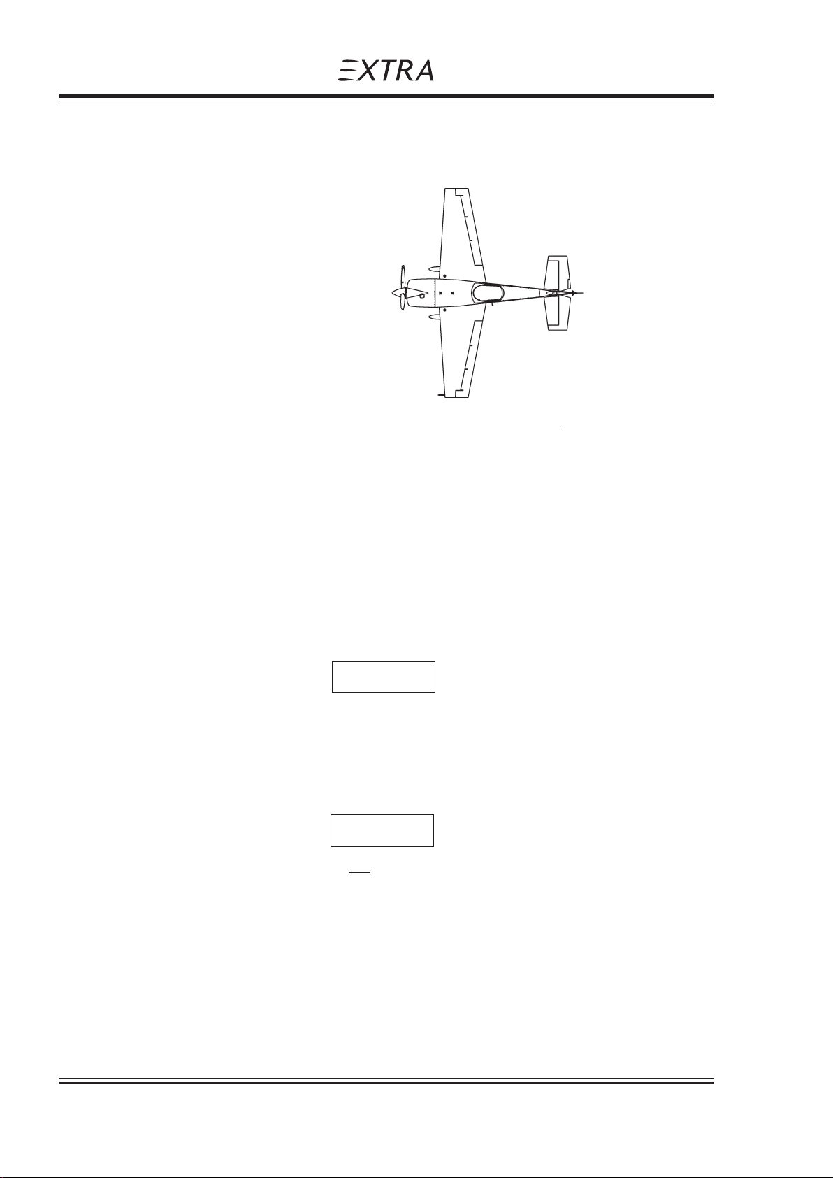
4.1.1 EXTERIOR INSPECTION ILLUSTRATION
4.1.2 GENERAL
Visually check airplane for general condition during walk around inspection.
Perform exterior check as outlined in the picture above in counterclockwise direction.
Pilot´s Operating Handbook
EXTRA 300/SC
3
4
2
1
5
4.2 CHECKLIST PROCEDURES
1) Cockpit
1. Pilot's Operating Handbook (AVAILABLE)
2. Airplane weight and balance CHECKED
3. Ignition switch OFF
4. Master switch ON
5. Fuel quantity indicator front center tank CHECK
6. Fuel quantity indicator rear center tank CHECK
Ensure at least one center tank having enough fuel for take-off, landing and
go-around.
7. Fuel quantity indicator wing tank CHECK
8. Master switch OFF
9. Fuel selector * ACRO & CENTER TANKS
Although safe operation does not require the use of the tanks in a specific sequence,
it is recommended to set fuel selector to "ACRO & CENTER TANKS" position!
NOTE
*NOTE
2) Empennage
1. All round inspection, canopy, surfaces,
stabilizers, elevator, trim tab, rudder and tailwheel CHECK
2. Horizontal stabilizer attachment bols CHECK FOR FREEPLAY BY
MOVING THE TIP OF THE
HORIZ. STABILIZER UP- AND
DOWNWARDS
4 - 4 Page Date: 29. February 2008
Page 45

Pilot´s Operating Handbook
EXTRA 300/SC
3) Right wing
1. Aileron, freedom of movement and security CHECK
2. Trailing edge CHECK
3. Fuel tank vent opening (right landing gear) CHECK
4. Fuel quantity CHECK
5. Fuel tank filler cap CHECK
6. Right landing gear, wheel and brake CHECK
4) Nose
1. Engine oil dipstick CHECK
2. Propeller and spinner CHECK
3. Air inlet CHECK
4. Fuel tank filler caps (front & rear center, wing) CHECK
5. Fuel drain for center & acro and wing tank DRAIN FOR AT LEAST 4
6. Fuel filter drain DRAIN FOR AT LEAST 4
Normal Procedures
Section 4
SECONDS TO CLEAR SUMP OF
POSSIBLE WATER;
CHECK CLOSED
SECONDS TO CLEAR
FILTER OF POSSIBLE WATER;
CHECK CLOSED
5) Left wing
1. Left landing gear, wheel and brakes CHECK
2. Fuel quantity CHECK
3. Fuel tank filler cap CHECK
4. Pitot cover REMOVE
5. Trailing edge CHECK
6. Aileron, freedom of movement and security CHECK
6) Before starting engine
1. Preflight inspection COMPLETE
2. Parachute CHECK SECURED
3. Seat, seatbelts, shoulder harnesses ADJUST AND LOCK
4. Canopy CLOSE AND LOCK
CAUTION
Handles of the canopy lock mechanism must be in the most opposite position indicated with
a red line on the canopy frame. Check gap between canopy frame and fuselage fairing!
5. Brake CHECK
6. Master switch ON
7. Electrical equipment OFF
Page Date: 29. February 2008 4 - 5
Page 46

Section 4
Normal Procedures
4.3 STARTING PROCEDURES
4.3.1 COLD ENGINES
The following starting procedures are recommended, however, the starting conditions may
necessitate some variation from these procedures.
1. Perform pre-flight inspection.
2. Set propeller governor control in "High RPM" position.
3. Open throttle approximately 1/4 travel.
4. Turn boost pump "ON".
5. Move mixture control to "FULL RICH" until a slight but steady fuel flow is noted
(approximately 3 to 5 seconds) and return mixture control to "IDLE CUT-OFF".
Turn bost pump "OFF".
6. Engage starter.
Pilot´s Operating Handbook
EXTRA 300/SC
7. When engine fires release the ignition switch back to "BOTH".
8. Move mixture control slowly and smoothly to "FULL RICH".
9. Check the oil pressure gauge. If minimum oil pressure is not
indicated within 30 seconds, shut off the engine and determine trouble.
4.3.2 HOT ENGINES
Because of the fact that the fuel percolates and the system must be cleared of vapor, it is
recommended to use the same procedure as outlined for cold engine start.
4.4 TAXIING THE AIRCRAFT
1. Canopy CLOSE AND LOCK
2. Brake CHECK
3. Altimeter Set on QFE or QNH
4. Electrical equipment ON
5. Radio Set and test
6. Mixture Leave in "FULL RICH" position
Operate only with the propeller in minimum blade angle (High RPM).
Warm-up at approximately 1000-1200 RPM. The engine is ready for take-off when the
throttle can be opened without the engine faltering.
Scale error max. +60 ft
4 - 6 Page Date: 29. February 2008
Page 47

Pilot´s Operating Handbook
EXTRA 300/SC
4.5 TAKE-OFF PROCEDURE
4.5.1 BEFORE TAKE-OFF
Before you line up at the runway for take-off:
- Check oil pressure and oil temperature.
- Check the magnetos on 1800 RPM. Allowed drop is 175 RPM
(max. difference 50 RPM).
- Check Alternator Output
- Move also the propeller control through its complete range to check operation and
return to full "High RPM" position. Turn boost pump "ON" (check indicator movement on
the fuel flow gauche).
4.5.2 TAKE-OFF
Set throttle smoothly to max. and let the airspeed go up to 65 to 70 KIAS (120 to 130 km/h).
A light pressure on the stick lifts the tail to horizontal position. Rotate the aircraft at 70 KIAS
(130 km/h). Proceed climbing at recommended climb speed.
Normal Procedures
Section 4
4.6 CLIMB
RPM above 2400 should be used only for acrobatic maneuvers when necessary for
maximum performance in order to avoid unnecessary noise.
Turn boost pump "OFF".
4.7 CRUISE
1. Altitude - As selected
2. Throttle/RPM - Adjust for cruising speed
3. Mixture - Adjust for minimum fuel consumption
4. Trim - As required
5. Fuel - Check periodically
Ensure at least one center tank having enough fuel for landing and go-around.
NOTE
Page Date: 29. February 2008 4 - 7
Page 48

Section 4
Normal Procedures
4.8 LANDING PROCEDURES
4.8.1 DESCENT
1. Throttle - Reduce
2. Mixture - "FULL RICH"
3. RPM Control - Set to 2400 RPM
4. Trim - Adjust
5. Fuel selector* - "ACRO & CENTER TANKS"
Although safe operation does not require the use of the tanks in a specific sequence, it is
recommended to set fuel selector to "ACRO & CENTER TANKS" position!
4.8.2 APPROACH
1. Boost pump - ON
2. Mixture - set to "Rich"
3. Airspeed - reduce to approach speed
4. Propeller pitch - set to low angle (High RPM).
Pilot´s Operating Handbook
EXTRA 300/SC
NOTE
It is recommended to set the RPM to 2400 during approach and landing
in order to avoid unnecessary noise.
In case of "Go Around", RPM control must be set to max. RPM before
applying power.
4.8.3 BEFORE LANDING
1. Landing approach - proceed at 85 KIAS (157 km/h)
2. Airspeed on final - maintain 85 KIAS (157 km/h)
3. Elevator trim - adjust
Stall speed will be
MTOW = 870 kg : 64 KIAS (119 km/h)
NOTE
NOTE
4 - 8 Page Date: 29. February 2008
Page 49

Pilot´s Operating Handbook
EXTRA 300/SC
4.8.4 NORMAL LANDING
1. Landing - perform as practicable
2. Touchdown - 3 point landing
The rudder is effective down to 30 KIAS (56 kmh)
3. Throttle - CLOSE / IDLE
4. Braking - Minimum required
4.9 GO-AROUND
Decide early in the approach if it is necessary to go around and
then start go-around before too low altitude and airspeed are
reached.
Normal Procedures
Section 4
with respect to surface
and weather condition
N O T E
Proceed as follows:
1. RPM control - "HIGH RPM" / Full forward
2. Throttle - "OPEN" / Take-off power
3. Airspeed - Minimum 90 KIAS (167 km/h)
4.10 SHUTDOWN
1. Boost pump - "OFF"
2. Engine - Run for 1 min. at 1000 RPM
3. Dead cut check - Perform
4. Electrical equipment - "OFF"
5. Mixture - "IDLE CUT OFF"
6. Ignition switch - "OFF"
7. Master switch - "OFF"
4.11 LEAVING THE AIRCRAFT
1. Canopy - Close and lock
2. Aircraft - Secure
3. Pitot cover - Attach
4. Log book - Complete
rotate to go-around altitude
Page Date: 29. February 2008 4 - 9
Page 50
Section 4
Normal Procedures
4.12 ACROBATIC MANEUVERS
4.12.1 GENERAL
Prior to executing these maneuvers tighten harnesses and check all loose items are
stowed. Start the maneuvers at safe altitude and max continuous power setting if not
otherwise noted.
For maneuver limits refer to Section 2 LIMITATIONS.
At high negative g-loads and zero g-periods it is normal that oil pressure and RPM indication
might drop down momentarily returning to normal status at positive g-loads.
The high permissible load factors of the airplane may exceed the individual physiological limits of pilot. This fact must be considered when pulling or pushing high g's.
Pilot´s Operating Handbook
EXTRA 300/SC
N O T E
WARNING
4.12.2 MANEUVERS
Particular caution must be exercised when performing maneuvers at speeds above
VA [158 KIAS (292 km/h)]. Large or abrupt control inputs above this speed may impose unacceptably high loads which exceed the structural capability of the aircraft.
Acrobatics is traditionally understood as maneuvers like loop, humpty bump, hammerhead
turn, aileron roll etc..
This manual does not undertake to teach acrobatics, however, it is meant to demonstrate
the plane's capabilities.
For this reason maneuvers are divided into segments. The segments are described.
Limitations are pointed out.
- Segment horizontal line:
A horizontal line may be flown with any speed between VS and V
- Segment line 45° climbing:
The plane will follow the line at max. power. The speed will not decrease below 80 KIAS
(148 km/h).
CAUTION
NE
- Segment line 90° up:
Any entry speed may be used. Out of a horizontal pull-up at 200 KIAS (370 km/h) the
vertical penetration will be 2.500 ft. The speed will gradually decrease to 0.
4 - 10 Page Date: 29. February 2008
Page 51

Pilot´s Operating Handbook
EXTRA 300/SC
In extremely long lines an RPM decay may occur. This is related to a loss of oil pressure.
Positive g´s should be pulled immediately in order to protect the engine. Oil pressure will
return immediately.
- Segment line 45° diving:
Throttle must be reduced in order to avoid exceeding VNE.
- Segment lin 90° diving:
Throttle must be reduced to idle in order to avoid exceeding VNE.
Above segments may be filled up with aileron rolls on snap rolls. Watch VA = 154 KIAS
(285 km/h) for aileron rolls with max. deflection.
Snap rolls should not be performed at speeds above 140 KIAS (259 km/h).
- Segment 1/4 loop, climbing:
The minimum recommended speed is 100 KIAS (185 km/h). If the maneuver is to be
followed by a vertical line, a higher entry speed is required depending on the expected
length of the line. A complete loop can be performed at speeds above 100 KIAS
(185 km/h).
Normal Procedures
Section 4
N O T E
4.12.3 SPIN
NOTE
Since the maximum horizontal speed is 183 KIAS (339 km/h), higher speeds should be
avoided in acrobatics since an unnecessary loss of altitude would occur.
- Torque maneuvers:
All maneuvers with high angular velocity associated with high propeller RPM must be
considered dangerous for the engine crankshaft.
Although wooden composite propeller blades are used, the gyroscopic forces at the prop
flange are extremely high.
CAUTION
If performing a gyroscopic maneuver such as flat spin, power on, or knife edge spin,
reduce RPM to 2400 in order to minimize the gyroscopic forces.
To enter a spin proceed as follows:
- Reduce speed, power idle
- When the plane stalls:
- kick rudder to desired spin direction
- hold ailerons neutral
- stick back (positive spinning), Stick forward (negative spinning)
Page Date: 29. February 2008 4 - 11
Page 52

Section 4
Normal Procedures
Pilot´s Operating Handbook
EXTRA 300/SC
The plane will immediately enter a stable spin.
- Ailerons against spin direction will make the spin flatter.
- Ailerons into spin direction will lead to a spiral dive.
Above apply for positive and negative spinning.
To stop the spin:
- Apply opposite rudder
- Make sure, power idle
- Hold ailerons neutral
- Stick to neutral position
After one turn of spinning the plane will recover within about 1/2 turn.
After six turns of spinning the plane will recover within about 1 turn.
Recovery can still be improved by feeding in in-spin ailerons.
N O T E
If ever disorientation should occur during spins (normal or inverted) one method always
works to stop the spin:
- Power idle
- Kick rudder to the heavier side
(this will always be against spin direction)
- Take hands off the stick
The spin will end after 1/2 thru 1 turn. The plane will be in a steep dive in a side-slip.
Recovery to normal flight can be performed easily.
N O T E
After one turn of spinning the altitude loss including recovery is within about 1500 ft.
After six turns of spinning the altitude loss including recovery is within about 3300 ft.
4 - 12 Page Date: 29. February 2008
Page 53

Pilot´s Operating Handbook
EXTRA 300/SC
Section 5
Performance
SECTION 5
PERFORMANCE
Table of Contents
Paragraph Page
SECTION 5 PERFORMANCE
5.1 GENERAL ........................................................................................................................... 5-3
5.1.1 Performance Charts ............................................................................................................ 5-3
5.1.2 Definitions of Terms.............................................................................................................5-3
5.1.3 Sample Problem.................................................................................................................. 5-3
5.2 ISA CONVERSION.............................................................................................................. 5-5
5.3 AIRSPEED CALIBRA TION ................................................................................................. 5-6
5.4 STALL SPEED .................................................................................................................... 5-7
5.5 TAKE-OFF PERFORMANCE.............................................................................................. 5-8
5.6 RA TE OF CLIMB PERFORMANCE.................................................................................... 5-9
5.7 TIME, FUEL & DISTANCE TO CLIMB.............................................................................. 5-10
5.8 CRUISE SPEED ................................................................................................................ 5-11
5.9 ENDURANCE ................................................................................................................... 5-12
5.10 RANGE ............................................................................................................................. 5-13
5.11 CRUISE PERFORMANCE ................................................................................................ 5-14
5.12 TIME , FUEL & DIST ANCE T O DESCEND....................................................................... 5-15
5.13 LANDING PERFORMANCE ............................................................................................. 5-16
Page Date: 29. February 2008 5 - 1
Page 54

Section 5
Performance
Pilot´s Operating Handbook
EXTRA 300/SC
Left blank intentionally
5 - 2 Page Date: 29. February 2008
Page 55

Pilot´s Operating Handbook
EXTRA 300/SC
5.1 GENERAL
Performance data charts on the following pages are presented to facilitate the planning of
flights in detail and with reasonable accuracy under various conditions.
It should be noted that the performance information presented in the range and endurance
charts allow for 45 minutes reserve fuel at specified conditions. Some indeterminate variables such as engine and propeller, air turbulence and others may account for variations as
high as 10% or more in range and endurance. Therefore, it is important to utilize all available
information to estimate the fuel required for the particular flight.
5.1.1 Performance Charts
Performance data are presented in tabular or graphical form to illustrate the effect of different variables. Sufficiently detailed information is provided in the tables so that conservative
values can be selected and used to determine the particular performance figure with
reasonable accuracy.
All speeds in this chapter are Indicated Air Speeds (IAS). The performance figures below
are given under following conditions:
1. Take-off Weight 870 kg (1918 lbs)
2. Take-off and landing on concrete surface.
3. No wind.
4. Standard atmospheric condition.
Section 5
Performance
SECTION 5
PERFORMANCE
5.1.2 Definitions of Terms
For definition of terms, abbreviations and symbols refer to section 1, General.
5.1.3 Sample Problem
Except in § 5.6 all examples presented in the performance charts refer to the conditions of
the sample problem outlined here.
CONDITIONS
Takeoff: Weight (MTOW): 870 kg (1918 lbs)
Cruise: Total Distance: 400 NM
Landing: Weight: 750 kg (1653 lbs)
Field Pressure Alt: 2000 ft (610 m)
Temperature: 15°C
Wind Component (Headwind): 10 KT
Field Length: 3000 ft
Pressure Altitude: 8000 ft (2438 m)
Temperature (ISA): -1°C
Field Pressure Alt: 2000 ft (610 m)
Temperature: 15°C
Wind Component (Headwind): 5 KT
Field Length: 2000 ft
Page Date: 29. February 2008 5 - 3
Page 56

Section 5
Performance
Pilot´s Operating Handbook
EXTRA 300/SC
TAKE-OFF
§ 5.5 shows the Take-Off Distance.
Example:
T/O Weight: 870 kg (1918 lbs)
Ground Roll: 138 m (453 ft)
(decreased by 8% due to headwind): 127 m (417 ft)
Total Distance to clear a 50 ft obstacle: 298 m (978 ft)
(decreased by 8% due to headwind): 274 m (899 ft)
These distances are well within the available field length in this sample problem.
CLIMB
§ 5.6 shows the Rate Of Climb Performance.
(conditions outlined in Fig. 5.6 deviate from the sample problem given here).
Pressure altitude: 6000 ft
Outside air temperatur: +5°C
Weight: 840 kg (1852 lbs)
Climb Rate: 1895 ft/min
§ 5.7 shows the Time, Fuel and Distance to Climb.
Example (climb from 2000 ft (610 m) to 8000 ft (2438 m)):
Time to Climb: (3.6 - 1.0) min = 2.6 min
Fuel to Climb: (7.5 - 2.0) Liters = 5.5 Liters (1.45 US Gal.)
Distance to Climb: (6.3 - 1.6) NM = 4.7m NM
CRUISE
Cruise Altitude and Power Setting should be determined for most economical fuel
consumption and several other considerations.
§ 5.11 shows the Cruise Performance data for a T/O Weight of 870 kg (1918 lbs) with
maximum fuel (224 l).
The conditions in the examples of the following Figures are:
Pressure altitude: 8000 ft (2438 m)
Power Setting: 65 %
§ 5.8 shows the cruise speed: 166 kts (307 km/h)
§ 5.9 shows the endurance: 3.3 h
§. 5.10 shows the range: 544 NM (1007 km)
The desired total distance in this sample problem is well within this value.
DESCENT
§ 5.12 shows Descent Time, Distance and Fuel data.
Example (descent from 8000 ft (2438 m) to 2000 ft (610 m)):
Time to Descent : (8 - 2) min = 6 min
Distance to Descent : (22.4 - 5) NM = 17.4 NM
Fuel to Descent : (4 - 1) Liters = 3 Liters (0.79 US Gal.)
5 - 4 Page Date: 29. February 2008
Page 57
Pilot´s Operating Handbook
EXTRA 300/SC
LANDING
§ 5.13 shows the Landing Distance.
Example:
Landing Weight: 750 kg (1653 lbs)
Ground Roll: 166 m (545 ft)
(decreased by 15% due to headwind): 141 m (463 ft)
Total Distance to clear a 50 ft obstacle: 511 m (1677 ft)
(decreased by 15% due to headwind): 434 m (1424 ft)
These distances are well within the available field length in this sample problem.
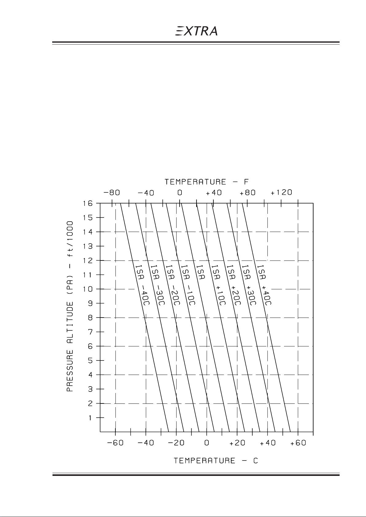
5.2 ISA CONVERSION
ISA Conversion of pressure altitude and outside air temperatur
Section 5
Performance
Page Date: 29. February 2008 5 - 5
Page 58
Section 5
Performance
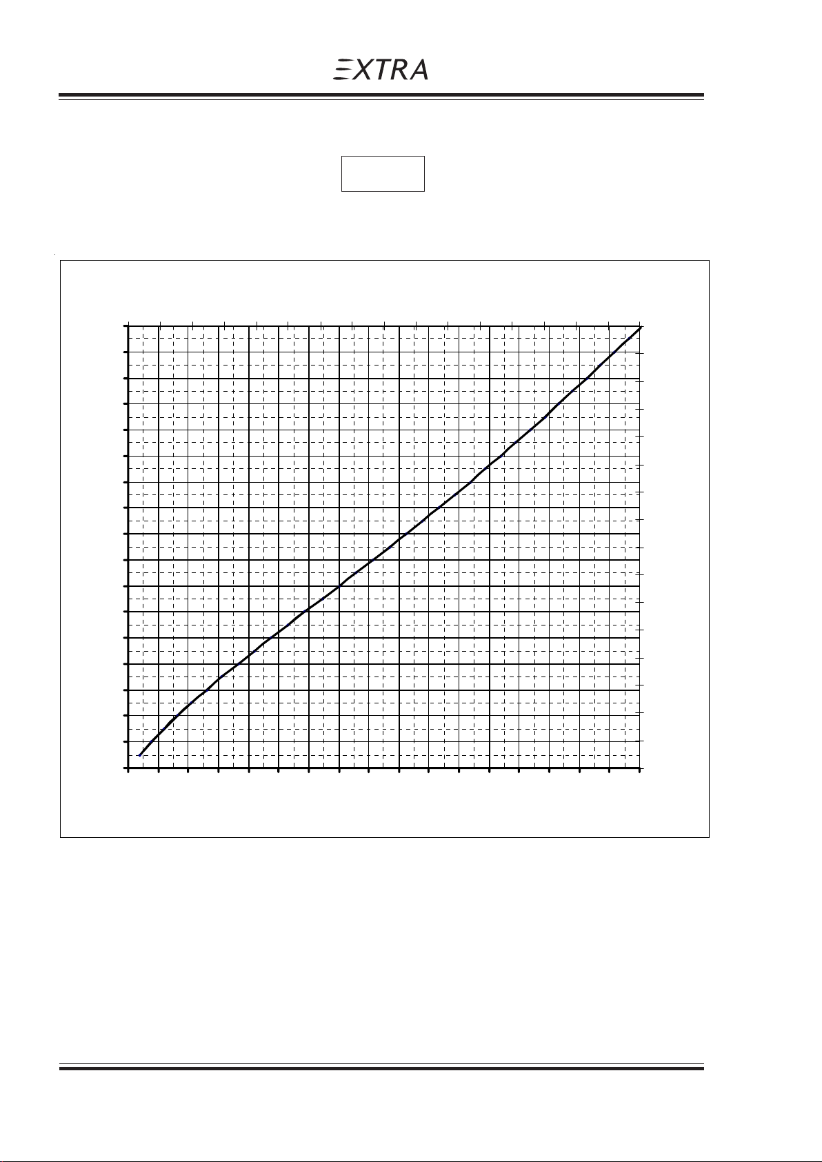
5.3 AIRSPEED CALIBRATION
Indicated airspeed assumes zero instrument error.
90 110 130 150 170 190 210 230 250 270 290 310 330 350 370 390 410
220
Pilot´s Operating Handbook
EXTRA 300/SC
NOTE
CAS [km/h]
410
210
200
190
180
170
160
150
140
KIAS
130
120
110
100
90
80
70
60
390
370
350
330
310
290
270
250
230
210
190
170
150
130
110
IAS [km/h]
50
90
50 60 70 80 90 100 110 120 130 140 150 160 170 180 190 200 210 220
KCAS
5 - 6 Page Date: 29. February 2008
Page 59

Pilot´s Operating Handbook
EXTRA 300/SC
5.4 STALL SPEED
CONDITION:
POWER IDLE
FORWARD C/G STALL SPEEDS
ANGLE OF BANK
WEIGHT CATEGORY 0° 30° 45° 60°
1g 1,15 g 1,41 g 2 g
KIAS (km/h) KIAS (km/h) KIAS (km/h) KIAS (km/h)
870 kg NORMAL 64 (119) 69 (128) 77 (143) 91 (169)
(1918 lbs)
780 kg ACRO 61 (113) 65 (120) 73 (135) 86 (159)
(1720 lbs)
Section 5
Performance
Max altitude loss during stall recovery is approximately 100 ft
Page Date: 29. February 2008 5 - 7
Page 60

Section 5
Performance
Pilot´s Operating Handbook
EXTRA 300/SC
5.5 TAKE-OFF PERFORMANCE
Power : T/O Power
Runway: Concrete
NOTE
For every 5 kts (9.3 km/h) headwind, the T/O distance can be decreased by 4%. For every
3 kts (5.6 km/h) Tailwind [up to 10 kts (18.5 km/h)], the T/O distance is increased by 10%.
On a solid, dry and plain Grass Runway, the T/O is increased by 15%.
OAT 0°C (32°F) 15°C (59°F) 30°C (86°F)
T/O Rotat- PA T/O T/O T/O T/O T/O T/O
weight ing Roll over Roll over Roll over
Speed 50 ft 50 ft 50 ft
kg (lbs) KIAS ft m (ft) m (ft) m (ft) m (ft) m (ft) m (ft)
870 70 SL 96 (315) 207 (679) 115 (377) 248 (813) 133 (436) 285 (935)
(1918) 2000 115 (377) 248 (814) 138 (453) 298 (978) 160 (525) 342 (1122)
4000 138 (453) 298 (978) 166 (545) 357 (1171) 192 (630) 410 (1345)
6000 166 (545) 358 (1175) 199 (653) 429 (1407) 230 (755) 492 (1614)
800 68 SL 78 (256) 167 (548) 93 (305) 200 (656) 107 (351) 230 (755)
(1764) 2000 94 (308) 200 (656) 112 (367) 240 (787) 128 (420) 276 (906)
4000 112 (367) 241 (791) 134 (440) 288 (945) 154 (505) 331 (1086)
6000 135 (443) 289 (948) 161 (528) 346 (1135) 185 (607) 397 (1302)
750 66 SL 67 (220) 114 (374) 79 (259) 170 (558) 93 (305) 200 (656)
(1653) 2000 80 (262) 173 (568) 95 (312) 204 (669) 112 (367) 240 (787)
4000 97 (318) 207 (679) 114 (374) 248 (814) 134 (440) 288 (945)
6000 116 (381) 249 (817) 137 (449) 294 (965) 161 (528) 347 (1138)
5 - 8 Page Date: 29. February 2008
Page 61
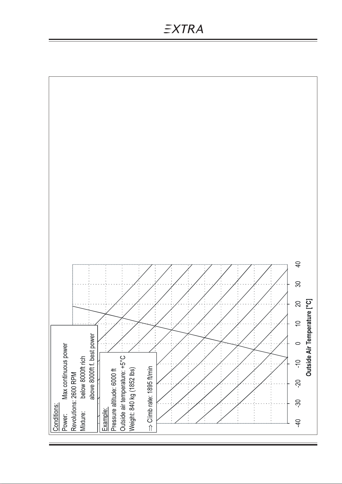
Pilot´s Operating Handbook
EXTRA 300/SC
5.6 RATE OF CLIMB PERFORMANCE
Section 5
Performance
Page Date: 29. February 2008 5 - 9
Page 62
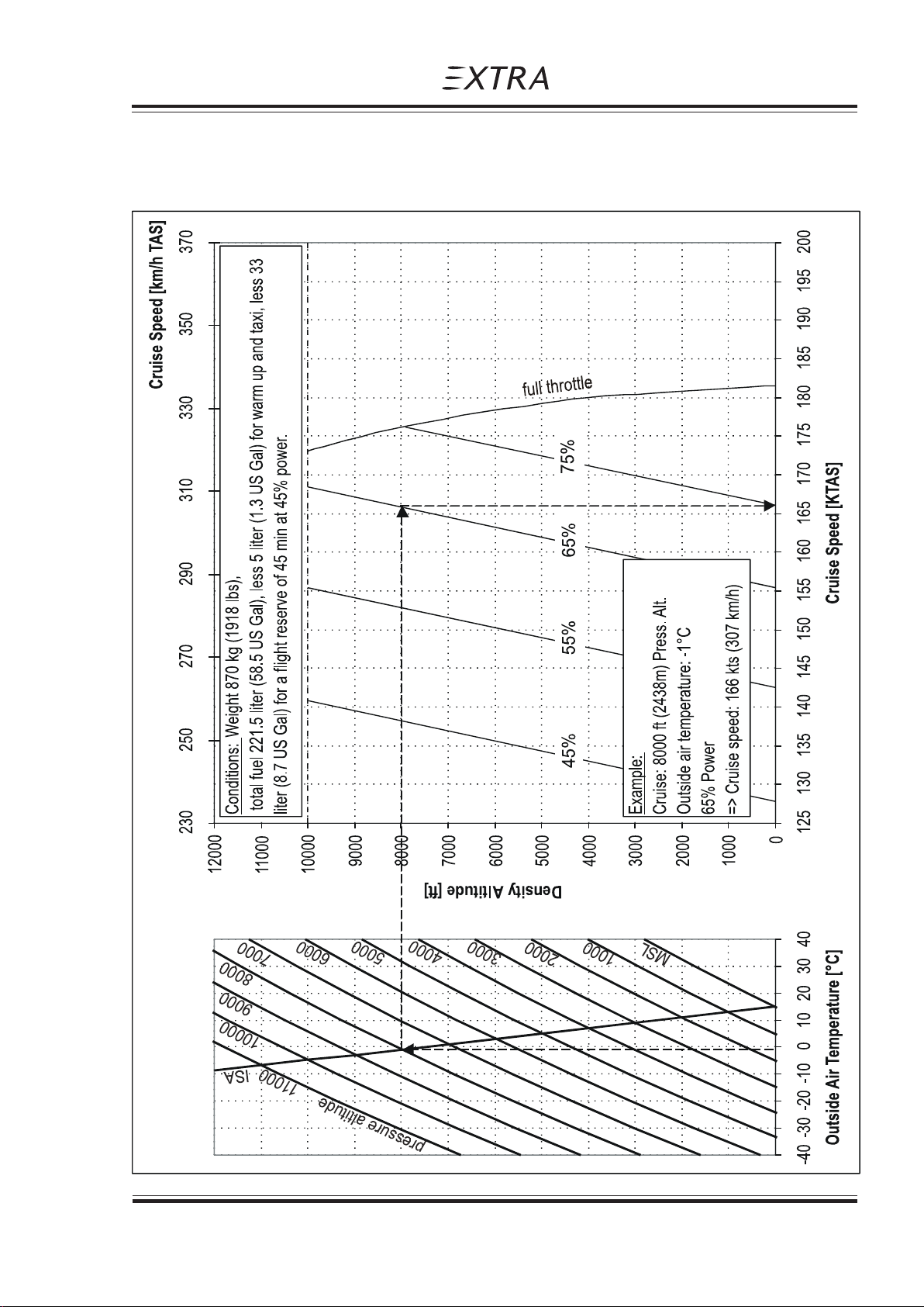
Pilot´s Operating Handbook
EXTRA 300/SC
5.8 CRUISE SPEED
Section 5
Performance
Page Date: 29. February 2008 5 - 11
Page 63
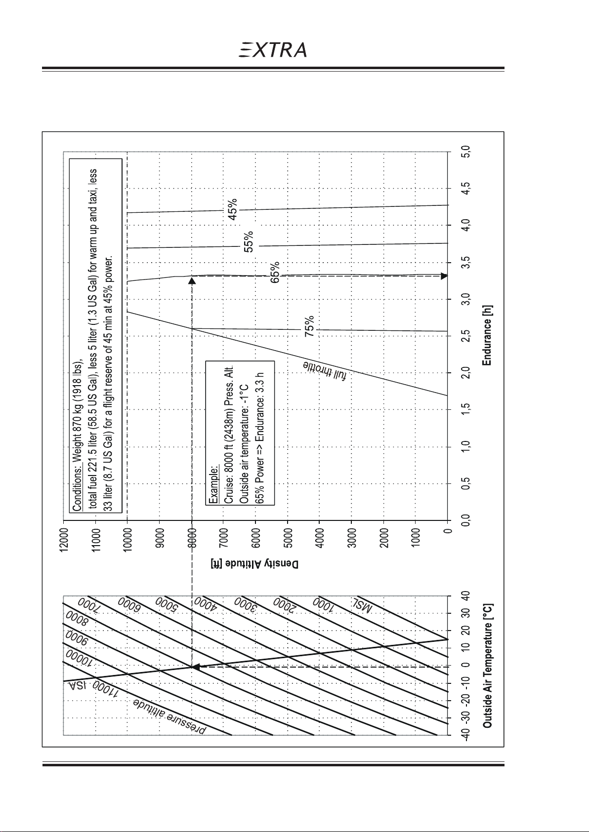
Section 5
Performance
5.9 ENDURANCE
Pilot´s Operating Handbook
EXTRA 300/SC
5 - 12 Page Date: 29. February 2008
Page 64
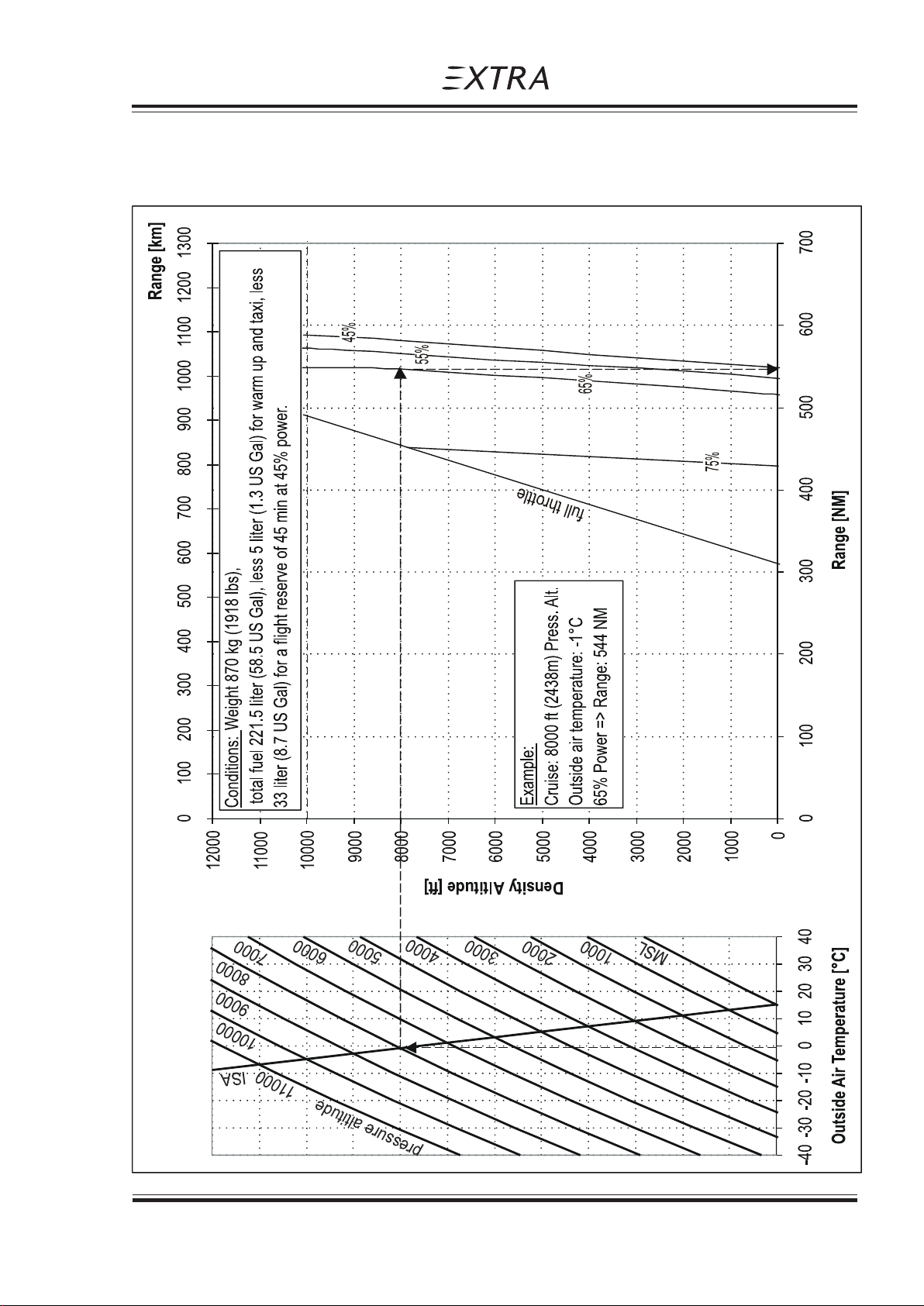
Pilot´s Operating Handbook
EXTRA 300/SC
5.10 RANGE
Section 5
Performance
Page Date: 29. February 2008 5 - 13
Page 65
Section 5
Performance
Pilot´s Operating Handbook
EXTRA 300/SC
5.11 CRUISE PERFORMANCE
Range and Endurance values for a T/O Weight of 870 kg (1918 lbs).Fuel for warm up and
Take-Off from SL, max continuous Power climb (2600 RPM) to cruising altitude, a reserve of
33 liter (8.7 US Gal.) for 45 minutes with 45% Power, and 3 liters (0.8 US Gal.) unusable
fuel are taken into account. (At ISA - Conditions.)
PA Eng. Manif. Power Setting Fuel TAS IAS Endur. Range Mixture
Press. Consumption 1 1 2
ft (m) RPM IN HG % Hp l/h (gal/h) Kts Kts h NM Best ...
2000 2600 27,3 91 288 86,7 22,9 180 176 2,13 381 Power
2500 26,5 85 268 79,7 21,1 176 172 2,32 406 Power
2400 24,9 75 236 71,5 18,9 169 165 2,58 433 Power
2200 23,9 65 205 55,2 14,6 158 154 3,32 524 Economy
2000 23,4 55 173 48,9 12,9 145 141 3,74 543 Economy
2000 20,1 45 142 43,0 11,4 130 126 4,25 555 Economy
4000 2600 25,3 85 268 79,7 21,1 179 169 2,33 412 Power
2400 24,9 75 236 71,5 18,9 171 161 2,58 439 Power
2200 23,9 65 205 55,2 14,6 161 151 3,32 531 Economy
2000 23,4 55 173 48,9 12,9 148 138 3,74 551 Economy
2000 20,1 45 142 43,0 11,4 133 123 4,24 564 Economy
6000 2600 22,6 75 236 71,5 18,9 174 161 2,59 446 Power
2200 23,9 65 205 55,2 14,6 163 150 3,32 538 Economy
2000 23,4 55 173 48,9 12,9 150 137 3,72 558 Economy
2000 20,1 45 142 43,0 11,4 136 123 4,22 572 Economy
8000 2600 20,1 65 205 55,2 14,6 166 151 3,31 544 Economy
2000 23,4 55 173 48,9 12,9 153 138 3,71 565 Economy
2000 20,1 45 142 43,0 11,4 138 123 4,19 580 Economy
10000 2600 17,3 55 173 48,9 12,9 156 135 3,69 571 Economy
2000 20,1 45 142 43,0 11,4 141 120 4,16 587 Economy
NOTE
1 For temperatures above/ below Standard (ISA), increase/decrease Range 1,7% and
Endurance 1,1% for each 10°C above/below Standard Day Temperature for particular
altitude.
2 "Best Power" or "Best Economy" see latest issue of Textron Lycoming AEIO-580-B1A
Operaton and Installation Manual Section I Part 3 (PN 60 297-32).
5 - 14 Page Date: 29. February 2008
Page 66
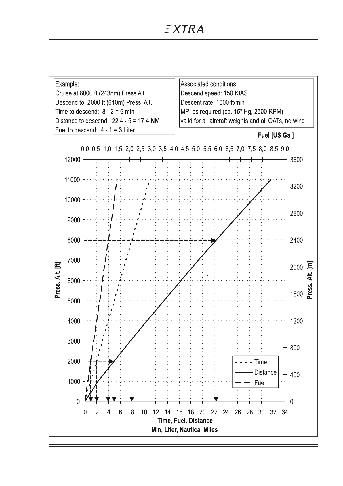
Pilot´s Operating Handbook
EXTRA 300/SC
5.12 TIME , FUEL & DISTANCE TO DESCEND
Section 5
Performance
Page Date: 29. February 2008 5 - 15
Page 67

Section 5
Performance
Pilot´s Operating Handbook
EXTRA 300/SC
5.13 LANDING PERFORMANCE
Power : Idle
Runway: Concrete
Brakes: maximum
NOTE
For every knot headwind, the landing distance can be decreased by 3%.
On a solid, dry and plain Grass Runway, the landing is increased by 15%.
OAT 0°C (32°F) 15°C (59°F) 30°C (86°F)
Landing Airspeed PA Land. Land. Land. Land. Land. Land.
weight Roll over Roll over Roll over
50 ft 50 ft 50 ft
[kg] / [KIAS] [ft] [m] / (ft) [m] /(ft) [m] / (ft) [m] / (ft) [m] / (ft) [m] / (ft)
(lbs)
870 85 SL 171 (561) 527 (1729) 177 (581) 548 (1798) 185 (607) 586 (1923)
(1918) 2000 181 (594) 558 (1831) 188 (617) 580 (1903) 197 (646) 602 (1975)
4000 192 (630) 592 (1942) 199 (653) 615 (2018) 208 (682) 639 (2096)
6000 203 (666) 627 (2057) 211 (692) 652 (2139) 220 (722) 678 (2224)
800 83 SL 158 (518) 488 (1601) 164 (538) 507 (1663) 171 (561) 527 (1729)
(1764) 2000 165 (541) 518 (1699) 175 (574) 537 (1762) 181 (594) 558 (1831)
4000 177 (581) 548 (1798) 185 (607) 570 (1870) 192 (630) 592 (1942)
6000 188 (617) 582 (1909) 195 (640) 605 (1985) 203 (666) 627 (2057)
750 81 SL 150 (492) 465 (1526) 156 (512) 483 (1585) 163 (535) 502 (1647)
(1653) 2000 159 (522) 492 (1614) 166 (545) 511 (1677) 173 (568) 532 (1745)
4000 168 (551) 522 (1713) 176 (577) 543 (1781) 184 (604) 565 (1854)
6000 179 (587) 553 (1814) 186 (610) 575 (1886) 194 (636) 598 (1962)
5 - 16 Page Date: 29. February 2008
Page 68

Pilot´s Operating Handbook
EXTRA 300/SC
Weight and Balance and Equipment List
Section 6
SECTION 6
WEIGHT AND BALANCE AND EQUIPMENT LIST
Table of Contents
Paragraph Page
SECTION 6 WEIGHT AND BALANCE AND EQUIPMENT LIST
6.1 GENERAL............................................................................................................................ 6-3
6.2 AIRCRAFT WEIGHING PROCEDURE ................................................................................. 6-3
6.2.1 Owners Weight and Balance Record.................................................................................... 6-4
6.3 CENTER OF GRAVITY CALCULA TION (SAMPLE PROBLEM)........................................... 6-5
6.3.1 Sample ................................................................................................................................ 6-7
6.3.2 Weight and Balance Record Sheet ...................................................................................... 6-7
6.4 LOADING WEIGHTS AND MOMENTS................................................................................ 6-8
6.5 WEIGHTS AND MOMENT LIMITS .................................................................................... 6-10
6.6 EQUIPMENT LIST.............................................................................................................. 6-11
Page Date: 29. February 2008 6 - 1
Page 69

Section 6
Weight and Balance and Equipment List
Pilot´s Operating Handbook
EXTRA 300/SC
Left blank intentionally
6 - 2 Page Date: 29. February 2008
Page 70
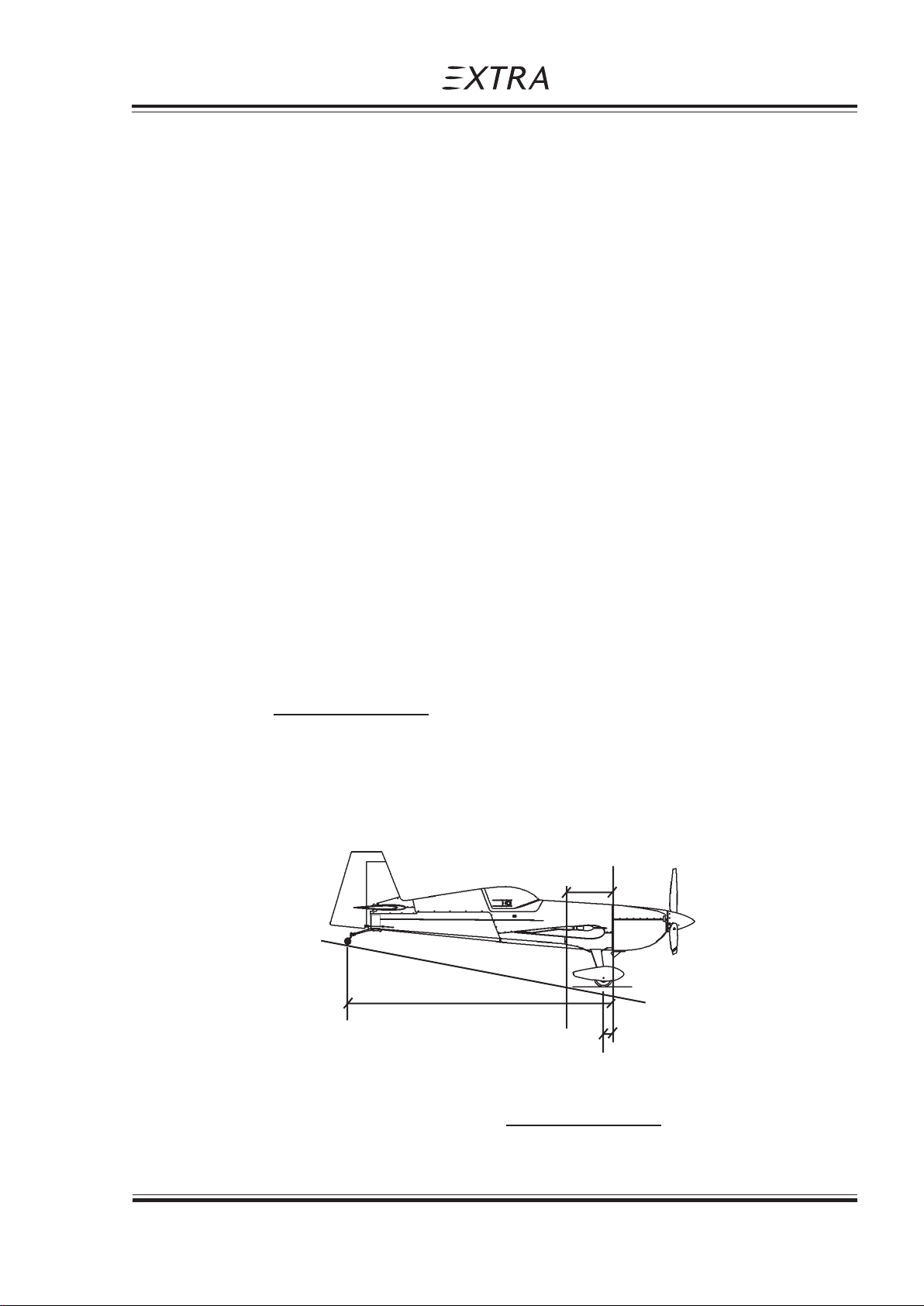
Pilot´s Operating Handbook
EXTRA 300/SC
6.1 GENERAL
This section describes the procedure for establishing the basic weight and moment of the
aircraft. Sample forms are provided for reference. Procedures for calculating the weight and
movement for various operations are also provided. A comprehensive list of all equipment
available for this aircraft is included. It is the responsibility of the pilot to ensure that the
aircraft is loaded properly.
6.2 AIRCRAFT WEIGHING PROCEDURE
The aircraft weight is determined by weighing all three wheel
loads simultaneously by three scales with the aircraft levelled.
(Upper fuselage reference line horizontal)
Datum line for weight arms x is the fire wall.
X1 = distance: fire wall - main wheel
X2 = distance: fire wall - tail wheel
Weight and Balance and Equipment List
Section 6
XN = distance: fire wall - item N
XG = distance: fire wall - Center of Gravity
W1 = Sum of weights indicated by the two scales below the main wheels
W2 = Weight indicated by the scale below the tail wheel
W = Total weight = W1 + W2
(W1 x X1) + (W2 x X2)
XG = = C/G position
W
Reference Firewall (plane)
x
G
x
2
W
2
W
W
x
1
1
(W1 x X1) + (W2 x X2)
W = W1 + W2 ,
Page Date: 29. February 2008 6 - 3
XG =
W
Page 71

Section 6
Weight and Balance and Equipment List
If a new weight is added to the known old weight and C/G position the resulting new weight
and C/G can be obtained by a simple calculation.
Situation before adding item:
Wo, Xo = Airplane weight, C/G position
Wn, Xn = Weight, distance from fire wall of item to add
New Weight of airplane and new C/G:
W = Wo + Wn
XG = Wo x Xo + Wn x Xn : C/G position
W
6.2.1 Owners Weight and Balance Record
Pilot´s Operating Handbook
EXTRA 300/SC
Enter below all weight change data from aircraft log book.
EXTRA 300/SC SERIAL NUMBER: REGISTRATION:
Date Description of Weight change Running empty
modification Added (+), Removed (-) weight
Wt./kg Arm/cm Moment/kg*cm Wt./kg Moment/kg*cm
[lbs] [inch] [lbs*inch] [lbs] [lbs*inch]
Empty weight ___ ___ _______
incl. unusable fuel
6 - 4 Page Date: 29. February 2008
Page 72
Pilot´s Operating Handbook
EXTRA 300/SC
Weight and Balance and Equipment List
6.3 CENTER OF GRAVITY CALCULATION (SAMPLE PROBLEM)
PILOT & FUEL IN FUEL IN FUEL IN OIL IN FUEL IN
PARACHUTE ACRO TANK REAR C. TANK FRONT C. TANK SMOKE TANK WING TANK
Position 9 LTR 41 LTR 54 LTR 23 LTR 120 LTR
(2.37 US GAL) (10.8 US GAL) (14.3 US GAL) (6.1 US GAL) (31.7 US GAL)
(kg) (lbs) (kg) (lbs) (kg) (lbs) (kg) (lbs) (kg) (lbs) (kg) (lbs)
169152.1 - - - - - - - -
Section 6
2
69 152.1 6.5 14.3 -- ----
369152.1 6.5 14.3 29.5 65----
469152.1 6.5 14.3 29.5 65 38.9 85.8 - -
569152.1 6.5 14.3 29.5 65 38.9 85.8 19.6 43.2
669152.1 6.5 14.3 29.5 65 38.9 85.8 19.6 43.2 86.4 190.5
799218.3 - - - - - - - -
8
9
10
99 218.3 6.5 14.3 - - - - - -
99 218.3 6.5 14.3 29.5 65----
99 218.3 6.5 14.3 29.5 65 38.9 85.8 - -
11 99 218.3 6.5 14.3 29.5 65 38.9 85.8 19.6 43.2
12 99 218.3 6.5 14.3 29.5 65 38.9 85.8 19.6 43.2 86.4 190.5
Refer to figure on next page
Page Date: 29. February 2008 6 - 5
Page 73
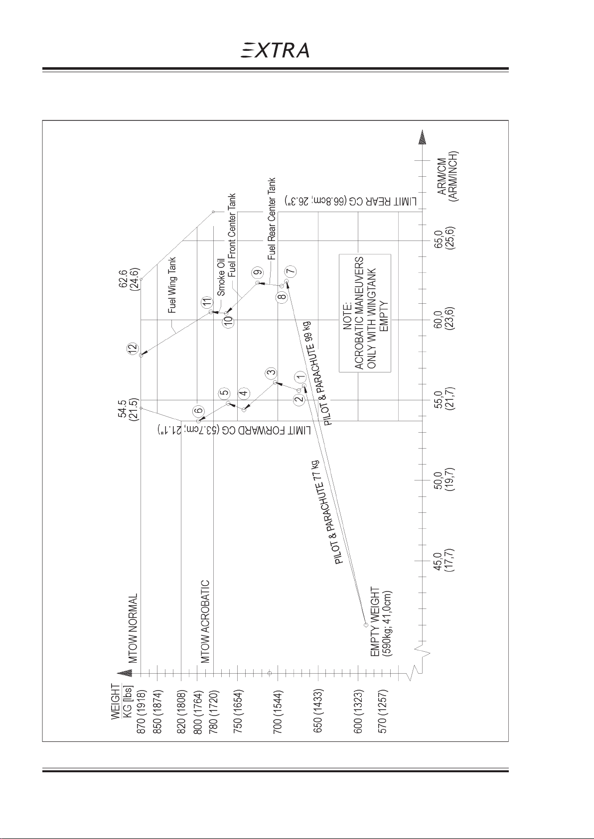
Section 6
Weight and Balance and Equipment List
6.3 CENTER OF GRAVITY CALCULATION (SAMPLE PROBLEM)(CONT.)
Pilot´s Operating Handbook
EXTRA 300/SC
6 - 6 Page Date: 29. February 2008
Page 74

Pilot´s Operating Handbook
EXTRA 300/SC
6.3.1 Sample
Refer to Center of Gravity Calculation Figure in § 6.3:
Take-off Condition:
Aircraft Empty Weight
(without any fuel) 590.0 kg (1300.7 lbs) 24190 k g c m (20996 i n lbs)
(7) Pilot & Parachute 99.0 kg (218.3 lbs) 18810 kg cm (16326 in lbs)
(8) Fuel in Acro Tank (9 L) 6.5 kg (14.3 lbs) 167 kg c m (145 in lbs)
(9) Fuel in Rear Center Tank (41 L) 29.5 kg (65.0 lbs) 2022 kg cm (1755 in lbs)
(10) Fuel In Front Center Tank (54 L) 38.9 kg (85.8 lbs) 921 kg cm (799 in lbs)
(11) Oil in Smoke Tank (Section 902) 19.6 kg (43.2 lbs) 1303 kg cm (1131 i n lbs)
(12) Fuel in Wing Tank (120L) 86.4 kg (190.5 lbs) 2851 k g cm (2475 in lbs)
===================================================================
To find C/G follow line "Pilot & Parachute 99 KG" from Empty Weight to Point 7.
Now follow line via points 8 thru 11 to point 12.
Weight and Balance and Equipment List
Section 6
Weights Moments
869.9 kg (1917.8 lbs) 50264 kgcm (43627 in lbs)
Refer to Weight and Moment Limits Figure in § 6.5 to find:
Weight 869.9 kg (1917.8lbs) Moment 50264 kg cm (43627 in lbs)
C/G ~ 57.8 cm (22.8 in)
6.3.2 Weight and Balance Record Sheet
EMPTY WEIGHT
PILOT (arm with respect to seat position)
FUEL ACRO TANK 25,8 cm (10,2")
FUEL REAR CENTER TANK 68,5 cm (27,0")
FUEL FRONT CENTER TANK 23,7 cm (9,3")
OIL SMOKE TANK (See Section 902) 66,5 cm (26,2")
FUEL WING TANK 33 cm (13,0")
WEIGHT ARM MOMENT
Σ Σ
Σ W =
Σ Σ
ΣΣ
Σ ( W x X )
ΣΣ
XG = =
Page Date: 29. February 2008 6 - 7
ΣΣ
Σ W
ΣΣ
ΣΣ
Σ ( W x X ) =
ΣΣ
Page 75
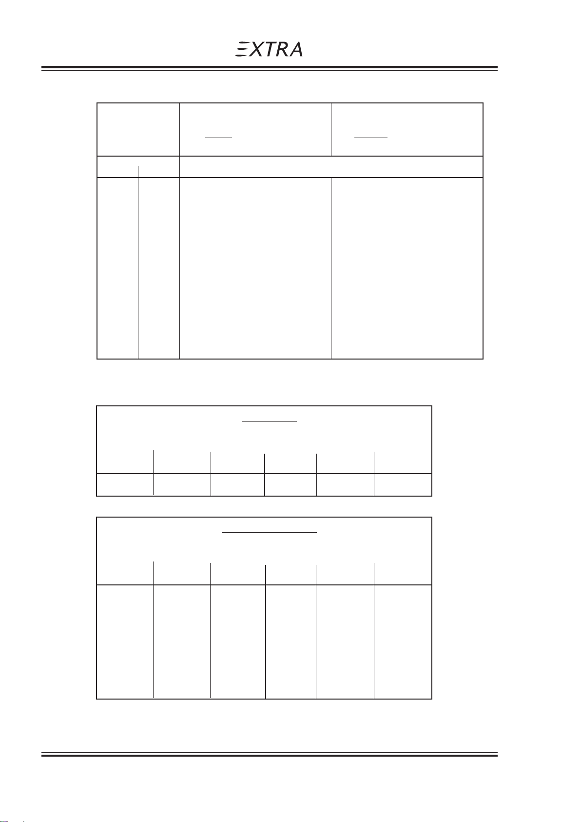
Section 6
Weight and Balance and Equipment List
6.4 LOADING WEIGHTS AND MOMENTS
WEIGHT PILOT PILOT
Pilot REAR SEAT POSITION FRONT SEAT POSITION
& Parachute ARM = 190 cm (75") ARM = 170 cm (67 ")
KG LBS MOMENT KG x CM (INCH x LBS)
70 154 13300 (11546) 11900 (10331)
75 165 14250 (12370) 12750 (11068)
80 176 15200 (13195) 13600 (11806)
85 187 16150 (14020) 14450 (12544)
90 198 17100 (14845) 15300 (13282)
95 209 18050 (15675) 16150 (14003)
Pilot´s Operating Handbook
EXTRA 300/SC
100 220 19000 (16500) 17000 (14740)
FUEL
ACRO TANK
Arm = 25,8 cm (10,2")
LITER (US GAL) KG (LBS) KG x CM (IN LBS)
9 2,4 6,5 14,3 167 145
REAR CENTER TANK
Arm = 68,5 cm (27,0")
LITER (US GAL) KG (LBS) KG x CM (IN LBS)
5 1,3 3,6 7,9 247 214
10 2,6 7,2 15,9 493 428
15 4,0 10,8 23,8 740 642
20 5,3 14,4 31,8 986 856
25 6,6 18,0 39,7 1233 1070
30 7,9 21,6 47,6 1480 1284
35 9,2 25,2 55,6 1726 1499
40 10,6 28,8 63,5 1973 1713
41 10,8 29,5 65,1 2022 1755
6 - 8 Page Date: 29. February 2008
Page 76
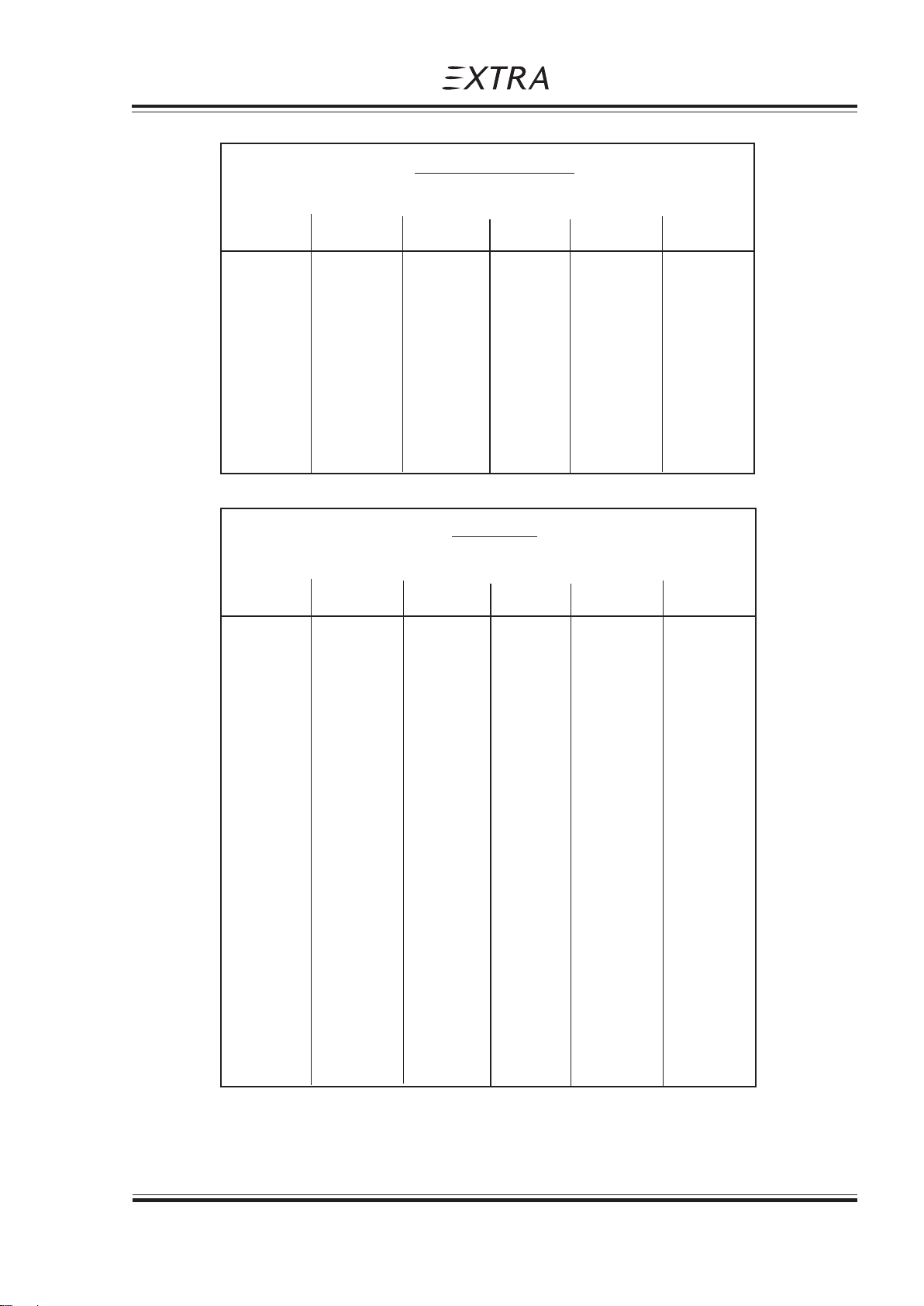
Pilot´s Operating Handbook
EXTRA 300/SC
LITER (US GAL) KG (LBS) KG x CM (IN LBS)
5 1,3 3,6 7,9 85 74
10 2,6 7,2 15,9 171 148
15 4,0 10,8 23,8 256 222
20 5,3 14,4 31,8 341 296
25 6,6 18,0 39,7 427 370
30 7,9 21,6 47,6 512 444
35 9,2 25,2 55,6 597 518
40 10,6 28,8 63,5 683 593
45 11,9 32,4 71,4 768 667
50 13,2 36,0 79,4 853 741
54 14,3 38,9 85,7 921 800
Weight and Balance and Equipment List
Section 6
FRONT CENTER TANK
Arm = 23,7 cm (9,3")
WING TANK
Arm = 33 cm (13,0")
LITER (US GAL) KG (LBS) KG x CM (IN LBS)
5 1,3 3,6 7,9 119 103
10 2,6 7,2 15,9 238 206
15 4,0 10,8 23,8 356 309
20 5,3 14,4 31,8 475 413
25 6,6 18,0 39,7 594 516
30 7,9 21,6 47,6 713 619
35 9,2 25,2 55,6 832 722
40 10,6 28,8 63,5 950 825
45 11,9 32,4 71,4 1069 928
50 13,2 36,0 79,4 1188 1031
55 14,5 39,6 87,3 1307 1134
60 15,8 43,2 95,3 1426 1238
65 17,2 46,8 103,2 1544 1341
70 18,5 50,4 111,1 1663 1444
75 19,8 54,0 119,1 1782 1547
80 21,1 57,6 127,0 1901 1650
85 22,4 61,2 134,9 2020 1753
90 23,8 64,8 142,9 2138 1856
95 25,1 68,4 150,8 2257 1959
100 26,4 72,0 158,8 2376 2063
105 27,7 75,6 166,7 2495 2166
110 29,0 79,2 174,6 2614 2269
115 30,4 82,8 182,6 2732 2372
120 31,7 86,4 190,5 2851 2475
Page Date: 29. February 2008 6 - 9
Page 77
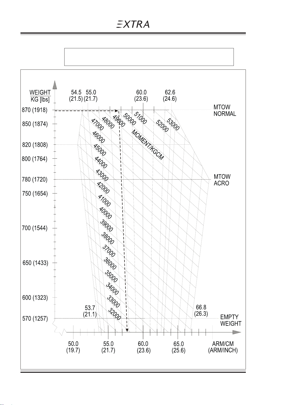
Section 6
Weight and Balance and Equipment List
6.5 WEIGHTS AND MOMENT LIMITS
EXAMPLE: At 869.9 kg (1917.8 lbs) and 50264 kgcm (43627 in lbs)
CG Location is 57.8 cm (22.8 in) aft of Reference Datum.
Pilot´s Operating Handbook
EXTRA 300/SC
CENTER OF GRAVITY - CM (INCH) AFT OF REF DATUM
6 - 10 Page Date: 29. February 2008
Page 78

Pilot´s Operating Handbook
EXTRA 300/SC
Weight and Balance and Equipment List
Section 6
6.6 EQUIPMENT LIST
EXTRA 300/SC S/N:
Qty. Item Manufacturer Part Nr. Weight Arm ROA* Inst
(kg) (m)
1 Exhaust System 6 in 1 (incl. Silencer) Gomolzig 00293 8.484 -0.390 R
1 Exhaust System 6 in 1 (w/o Silencer) Sky Dynamics 32347 7.421 -0.390 A
1 Ammeter (+/-30A) VDO 32406 0.080 1.260 R
1 Ammeter (+/-20A) Datcon 33413 0.134 1.260 A
1 Battery Concorde 03617 10.519 0.175 R
1 RPM Indicator Horizon 02489 0.294 1.260 R
1 Oil Press / Oil Temp Ind. System (2 1/4") Westach FI3002 0.212 0.521 R
1 CHT/EGT Ind. System (2 1/4") Westach 32570 0.174 1.260 O
1 EDM 800 System J P I 93102.029-PG 2.250 0.106 O
1 Manifold Pressure / Fuel Flow Ind. United Instr. 03247 0.540 1.260 R
1 Fuel Qty Ind. Front Center Tank VDO 00390 0.120 1.260 R
1 Fuel Qty Ind. Front Center Tank Datcon 33411 0.145 1.260 A
1 Fuel Qty Ind. Rear Center Tank VDO 00390 0.120 1.260 R
1 Fuel Qty Ind. Rear Center Tank Datcon 33411 0.145 1.260 A
1 Fuel Qty. Ind. Wing Tank VDO 200171 0.120 1.260 R
1 Fuel Qty. Ind. Wing Tank Datcon 33412 0.145 1.260 A
1 Fuel Qty Probe Front Center Tank VDO 32610 0.184 0.220 R
1 Fuel Qty Probe Front Center Tank Datcon 33410 0.212 0.220 A
1 Fuel Qty Probe Rear Center Tank VDO 32611 0.184 0.700 R
1 Fuel Qty Probe Rear Center Tank Datcon 33409 0.212 0.700 A
1 Fuel Qty Probe Wing Tank VDO FM4006 0.120 0.280 R
1 Accelerometer (2 1/4") Falcon 01206 0.294 1.270 R
1 Digital Accelerometer System (2 1/4") TL 32582 0.520 1.265 A
1 Magnetic Compass Airpath 00189 0.260 1.290 R
1 Magnetic Compass SIRS Navigation Ltd 33085 0.132 1.290 A
1 Air Speed Indicator United Instr. FI0003 0.322 1.290 R
1 Air Speed Indicator (Metrisch) Winter 02285 0.205 1.290 A
1 Altimeter United Instr. 30416 0.610 1.280 R
1 Altimeter (Metrisch) Winter 31393 0.330 1.280 A
1 Horizon, electric digital RC Allen 33027 (0° tilt) 0.241 1.225 O
1 Horizon, electric digital RC Allen 33217 (0° tilt) 0.454 1.217 O
1 Flighthour Counter Winter 01605 0.150 1.260 O
1 Digital Clock Astrotech FI0004 0.113 1.260 O
2 Main Wheel Tires Misc. 02323 2.447 0.110 R
1/1 Wheel fairing (CFK) Extra 53102.301-LV-L/R 1.500 0.160 O
1 Instrument Panel Extra 7C102.001 0.400 1.300 R
1 Instrument Panel, alternative Extra 8C503.007/8/9 0.470 1.300 A
1 12V Power Socket Sutars 31494 0.028 1.290 O
1 VHF-COM Becker 00652 0.712 1.200 R
1 Transponder (Mode A/C) ATC4401 Becker 31002 0.730 1.200 O
*) R = required, O = optional, A = alternative
Page Date: 10. January 2011
Page Date: 29. February 2008 6 - 11
Page 79

Section 6
Weight and Balance and Equipment List
Pilot´s Operating Handbook
EXTRA 300/SC
Qty. Item Manufacturer Part Nr. Weight Arm ROA* Inst
(kg) (m)
1 Transponder (Mode S) BXP6401-2-(01) Becker 31860 0.780 1.200 OA
1 Slip and Skid ind. (Libelle) Rieker FI0009 0.050 1.310 O
1 ELT 3000 System 3000-10/-11 Pointer 50025/02154 0.990 1.383 O
1 ME406 ELT 406MHz System Artex 32173 1.205 1.360 OA
1 Single Pump Smoke System Extra 8C111.001-VM 4.591 0.605 O
1 External Power Receptical (Piper Type Socket) Cole Hersee 31731 1.300 1.900 O
1/1 Sighting device (45°/90°), Carbon Extra 8C801.030-01/02 0.25 1.260 O
1/1 Electric Actuator Pedal Adjust. SKF 01996 3,25 1.605 O
each
*) R = required, O = optional, A = alternative
6 - 12 Page Date: 29. February 2008
Page Date: 10. January 2011
Page 80

Pilot´s Operating Handbook
EXTRA 300/SC
Description and Operation of Aircraft and Systems
Section 7
SECTION 7
DESCPRIPTION AND OPERATION
OF AIRCRAFT AND SYSTEMS
Table of Contents
Paragraph Page
SECTION 7 DESCPRIPTION AND OPERATION OF AIRCRAFT AND SYSTEMS
7.1 THE AIRCRAFT .................................................................................................................. 7-3
7.2 FUSELAGE ......................................................................................................................... 7-3
7.3 WINGS ................................................................................................................................ 7-3
7.4 EMPENNAGE ..................................................................................................................... 7-4
7.5 FLIGHT CONTROL SYSTEM............................................................................................. 7-4
7.5.1 Primary Control System....................................................................................................... 7-4
7.5.2 Longitudinal Flight Control System ...................................................................................... 7-4
7.5.3 Lateral Flight Control System .............................................................................................. 7-4
7.5.4 Directional Flight Control System ........................................................................................ 7-4
7.5.5 Secondary Control...............................................................................................................7-4
7.6 INSTRUMENT P ANEL ........................................................................................................ 7-6
7.7 LANDING GEAR................................................................................................................. 7-7
7.8 SEA TS, SEA T BELTS ......................................................................................................... 7-8
7.9 CANOPY ............................................................................................................................. 7-8
7.10 POWER PLANT.................................................................................................................. 7-8
7.10.1 Engine ................................................................................................................................. 7-8
7.10.2 Oil System........................................................................................................................... 7-9
7.10.3 Engine Installation ............................................................................................................... 7-9
7.10.4 Propeller .............................................................................................................................. 7-9
7.10.5 Throttle ................................................................................................................................ 7-9
7.10.6 Mixture .............................................................................................................................. 7-10
7.10.7 RPM-Control .....................................................................................................................7-10
7.10.8 Fuel Selector Valve............................................................................................................ 7-10
7.10.9 Exhaust System ................................................................................................................ 7-10
7.11 FUEL SYSTEM ................................................................................................................. 7-10
7.12 ELECTRICAL SYSTEM .................................................................................................... 7-13
7.13 CABIN ENVIRONMENT CONTROL ................................................................................. 7-13
Page Date: 29. February 2008 7 - 1
Page Date: 29. February 2008
Page 81

Section 7
Description and Operation of Aircraft and Systems
Pilot´s Operating Handbook
EXTRA 300/SC
Left blank intentionally
7 - 2 Page Date: 29. February 2008
Page 82

Pilot´s Operating Handbook
EXTRA 300/SC
7.1 THE AIRCRAFT
The aircraft EXTRA 300/SC is designed and developed by EXTRA Flugzeugproduktionsund Vertriebs- GmbH, Dinslaken 46569 Hünxe, Federal Republic of Germany, in
accordance with the Joint Aviation Authorities FAR-23 acrobatic category to fullfill the
primary flight training, and acrobatic training up to the unlimited acrobatic level.
EXTRA 300/SC is a light weight, robust, single piston-engined, one-seat aircraft with a
fuselage structure in tig-welded steel-tube construction.
The landing gear, wing, and tail are made of epoxy, reinforced with glass- and carbonfiber.
The items are qualified up to 72°C.
The aircraft is designed to operate within a range of ambient air temperature from -20°C to
+38°C (-4°F => 100°F) at sea level. It is possible to start the engine using the aircraft battery
at -20°C (-4°F) without preheating.
Description and Operation of Aircraft and Systems
Section 7
SECTION 7
DESCPRIPTION AND OPERATION
OF AIRCRAFT AND SYSTEMS
7.2 FUSELAGE
The fuselage structure consists of a steel tube construction integrating the wing and
empennage connections as well as the seat. The lower part of the fuselage and the sides
below the wing are covered with a carbon belly fairing. Within the exhaust area aluminum
sheet metal is used. The rear part of the fuselage is covered with Ceconite® 102.
The upper fuselage body surface is one part from firewall to vertical stabilizer including the
correlated frame for the canopy. It consists of a carbon sandwich laminate.
The canopy itself is a single part. The canopy frame is a carbon laminate construction.
For additional pilot protection a roll bar is installed behind the pilot's seat.
7.3 WINGS
The wing is a CRP construction. The dual chamber main spar - being a fail safe design consists of carbon roving caps combined with CRP webs. Core foam is a PVC foam. The
wing shell is built by a Honeycomb sandwich with CRP laminates. Wing box ribs are made
of carbon fiber composite with honeycomb core. The ribs in the nose section are made of
wood. The connection to the fuselage is arranged by two bolts piercing through the spar
parallel to the centerline of the fuselage and two brackets at the rear spars.
The ailerons are supported at four points in spherical bearings. In addition the aileron tip has
a shielded horn balance.
To reduce pilot's hand forces the hinge line of the ailerons is positioned 25% of the aileron
chord. Furthermore the ailerons are equipped with "spades" to decrease pilot's forces. The
aileron control push-pull rods are connected to the aileron at the second bearing point (in
span-wise direction). To prevent flutter the ailerons are mass balanced at the leading edge
of the shielded horn.
Page Date: 29. February 2008 7 - 3
Page 83

Section 7
Description and Operation of Aircraft and Systems
7.4 EMPENNAGE
The EXTRA 300/SC possesses a cruziform empennage with stabilizers and moveable
control surfaces. The spars consist of PVC foam cores, CRP caps and webs. The shell is
built by honeycomb sandwich with CRP laminates. The control surfaces are are mounted in
spherical bearings and balanced aerodynamically with unshielded horns at the tip. To
prevent flutter rudder and elevator are mass balanced. The balance weights are installed in
the leading edges of the unshielded horn´s.
The R/H elevator side incorporates a trim tab supported at two piano type hinges.
7.5 FLIGHT CONTROL SYSTEM
7.5.1 PRIMARY CONTROL SYSTEM
The EXTRA 300/SC is equipped with a conventional control stick and mechanically
adjustable rudder pedals. The primary control surfaces are operated through a direct
mechanical linkage.
7.5.2 LONGITUDINAL FLIGHT CONTROL SYSTEM
Pilot´s Operating Handbook
EXTRA 300/SC
The control stick bearing is housed in a torque tube, which is also linked to the lateral flight
controls. The stick movements are transferred to the elevator by carbon push-pull rods.
7.5.3 LATERAL FLIGHT CONTROL SYSTEM
Aluminium and carbon push-pull rods connect the torque tube to the ailerons. The
connections feature sealed rod ends. The ailerons are statically as well as dynamically
balanced. (Dynamically with spades).
The ailerons are supported by lubricated, sealed bearings.
7.5.4 DIRECTIONAL FLIGHT CONTROL SYSTEM
The rudder pedals with brake pedals are mechanically adjustable and operate the rudder
through a control cable system. Springs keep the cables under tension when the pedals are
not operated.
7.5.5 SECONDARY CONTROL
The elevator trim uses a trim servo connected to the trim tab by a double Bowden cable.
The trim switch is either located on the control stick or together with the trim position
indicator on the right upper side of the instrument panel. The double cable actuation of the
trim tab is a fail safe design to prevent flutter in case of a single control joint failure.
The canopy is operated from the inside and outside by the interior locking handles. These
handles are used for locking as well as for normal and emergency operation.
The starter/magneto switch is located on the left side of the instrument panel.
7 - 4 Page Date: 29. February 2008
Page Date: 12. February 2010
Page 84

Pilot´s Operating Handbook
EXTRA 300/SC
Description and Operation of Aircraft and Systems
Section 7
Left blank intentionally
Page Date: 29. February 2008 7 - 5
Page 85
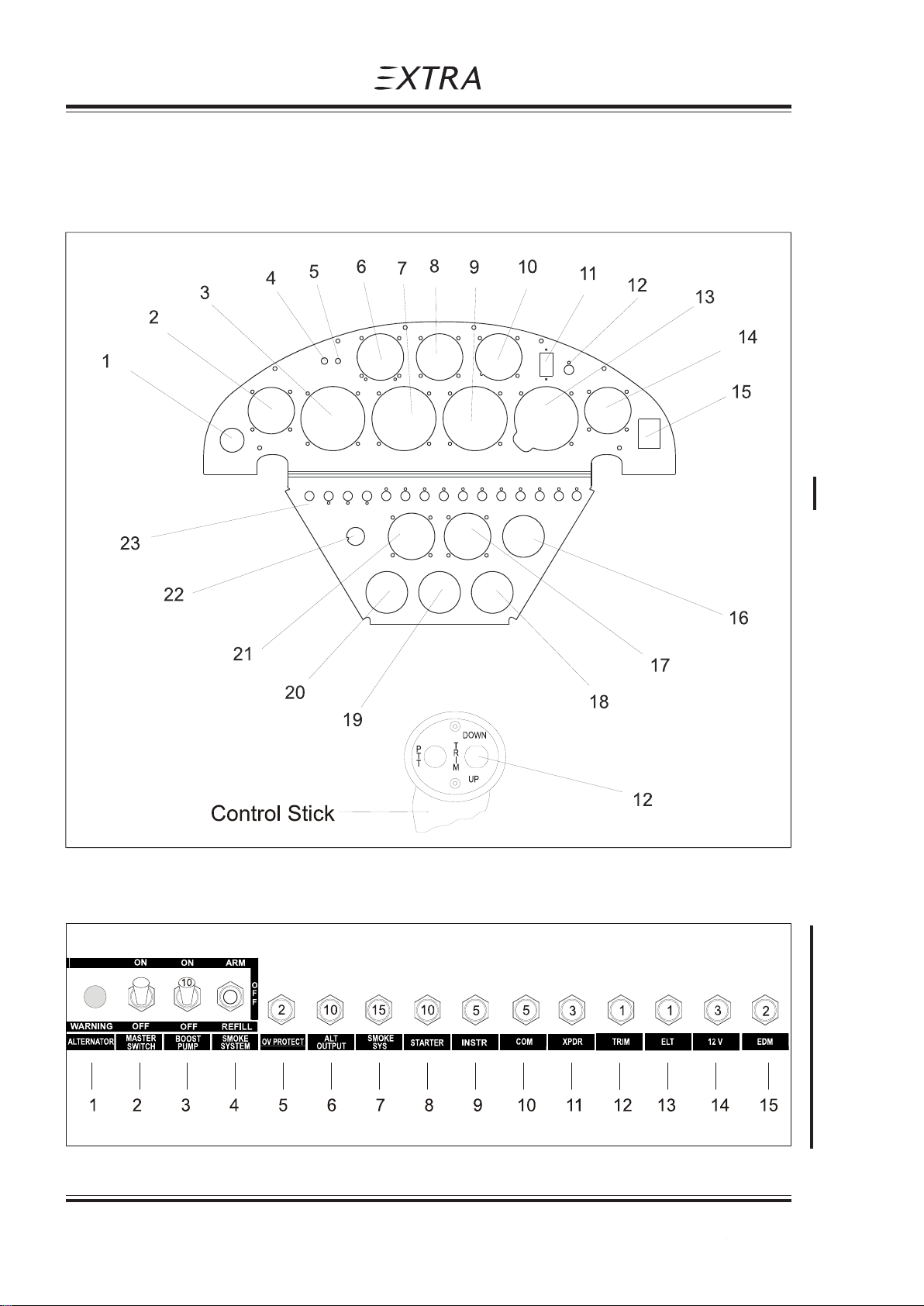
Section 7
Description and Operation of Aircraft and Systems
7.6 INSTRUMENT PANEL
Refer to the following figures and the related lists for the instruments, switches, lamps and
circuit breakers installed in the EXTRA 300/SC.
Pilot´s Operating Handbook
EXTRA 300/SC
Figure 7-1: Instrument panel
Figure 7-2: Switches, circuit breakers, light
7 - 6 Page Date: 29. February 2008
Page Date: 10. January 2011
Page 86

Pilot´s Operating Handbook
EXTRA 300/SC
Position Item
1 12 Volt power source jack
2 COM
3 Air speed indicator
4 EDM 800 Data port
5 EDM 800 FF/EGT-switch
6 EDM 800
7 Manifold pressure / fuel flow
8 Magn. direction indicator
9 RPM indicator
10 Accelerometer
11 Trim position indicator
12 Trim position switch (on panel or control stick)
13 Altimeter
14 XPDR
15 ELT
16 Ammeter
17 Oil pressure / oil temperature
18 Fuel quantity Rear center tank
19 Fuel quantity Front center tank
20 Fuel quantity Wing tanks
21 EGT / CHT indicator
22 Magneto selector switch & starter
23 Switches, circuit breakers, light as listed below:
Description and Operation of Aircraft and Systems
Section 7
Switches, Circuit Breakers, Light (Figure 7-2)
Position Item
1 Alternator warning light incl. press-to-test feature
2 Master switch
3 Boost pump switch circuit breaker
4 Smoke system switch
5 Overvoltage protection circuit breaker
6 Alternator output circuit breaker
7 Smoke system circuit breaker
8 Starter circuit breaker
9 Instruments circuit breaker
10 COM circuit breaker
11 XPDR circuit breaker
12 TRIM circuit breaker
13 ELT circuit breaker
14 12 V circuit breaker
15 EDM 800 circuit breaker
These lists may be modified by the minimum equipment requirements of individual
certifying authorities!
7.7 LANDING GEAR
NOTE
The EXTRA 300/SC is designed as a conventional tail-wheel airplane. The main gear is a
composite construction with a multichamber spring made of glass fiber webs and caps. The
main wheels have a size of 5.00-5 and they are equipped with hydraulic disc brakes. The tail
wheel has a solid rubber tire with full-swivel capability.
Page Date: 29. February 2008 7 - 7
Page Date: 10. January 2011
Page 87

Section 7
Description and Operation of Aircraft and Systems
7.8 SEATS, SEAT BELTS
The seat is a shaped carbon composite construction. It´s back rest position and angle is
mechanically adjustable on ground by quickpins and bolts. The lower seat surface itself is
fixed.
The seat belt assembly consists of right and left shoulder straps, two right and two left lap
belts and a negative g-strap. All belts are adjustable. The lap belts have a separate single
point release for redundant safety during acrobatic maneuvers. If one release is opened
unintentionally the second one guarantees full safety. To assure safe operation one release
must be closed to the right and the other one to the left. For acrobatic maneuvers the seat
belt system should be tightened firmly.
7.9 CANOPY
The canopy is manufactured in one section and can be manually operated by interior locking
handles located on the left side on the canopy.
To open the canopy from inside proceed as follows: Pull together the interior locking handles
and lift canopy to the right. The canopy strap will limit the opening angle.
To lock the canopy pull together the interior locking handles and then release.
To open the canopy from the outside use the interior handles by reaching through the small
window (bad weather window) and proceed as mentioned above.
Generally the emergency operation is equal to the normal procedure. When opening the
canopy in normal flight the low pressure over the canopy will flip the canopy fully open
immediately. However complete jettison of the canopy is possible. In this case the canopy
can be finally unlatched at its RH hinge line by the following action: push canopy slightly
forward while opening.
Pilot´s Operating Handbook
EXTRA 300/SC
7.10 POWER PLANT
7.10.1 ENGINE
The power plant consists of one Textron-Lycoming six-cylinder, horizontally opposed,
aircooled, direct drive, fuel injection engine type with inverted oil system.
The rated power at 2700 RPM is 315 HP (234.9 kW).
The rated power at 2600 RPM is 303 HP (225.9 kW).
The rated power at 2400 RPM is 286 HP (213.3 kW).
Engine specification: Textron - Lycoming AEIO-580-B1A
The AEIO-580-B1A engine is equipped with special antivibration counterweights.
The following accessories are included in the power plant
installation:
-Fuel Injector: Precision
-Magnetos: Slick
-Alternator: B&C
-Starter: Sky-Tec
-Fuel pump: Gates Lear
-Shielded ignition system
-Propeller governor drive
-Transistor voltage regulator
7 - 8 Page Date: 29. February 2008
Page 88

Pilot´s Operating Handbook
EXTRA 300/SC
The engine is operated with the following manual controls:
The propeller governor monitors the RPM automatically and prevents overspeeding. In the
event that oil pressure is lost the propeller is automatically adjusted to coarse pitch in order
to avoid overspeeding.
100/130 aviation grade fuel (AVGAS 100/100LL) is the minimum grade recommended by
the manufacturer of the engine.
100/130 aviation fuel is also the maximum grade.
7.10.2 OIL SYSTEM
The engine oil is cooled using a Single Oil Cooler. The oil cooler is mounted on the aft, right
hand side of the engine. The oil level is determined by a dip-stick which is accessible
through an opening in the upper cowling.
Description and Operation of Aircraft and Systems
Section 7
-Throttle control
-RPM control
-Fuel mixture control
Oil capacity:
Max. sump capacity: 16 qts.
Min. sump capacity: 9 qts.
WIth the engine in good condition the minimum engine oil capacity is safe for maximum
endurance in the aerobatic category.
For temperatures and oil grades refer to Section 1.7.
7.10.3 ENGINE INSTALLATION
The engine is mounted with four shock-mounts to the tig-welded steel tube engine support,
which is attached to the fuselage with four bolts on the firewall plane.
The engine cowling is divided into two parts, a lower and an upper part both made of carbon
fibre reinforced epoxy. The parts are fixed by a number of screws and the upper cowling has
a separate hatch for easy access to the oil dip-stick.
NOTE
7.10.4 PROPELLER
The propeller is a 3-blade wood composite, constant speed propeller type MTV-9-B-C/C19825 with a diameter of 1,98 m.
7.10.5 THROTTLE
Control lever (cub-type) mounted on the left side of the cockpit.
Page Date: 29. February 2008 7 - 9
Page 89

Section 7
Description and Operation of Aircraft and Systems
7.10.6 MIXTURE
Vernier control located at the right side of the cockpit (red knob).
7.10.7 RPM-CONTROL
Vernier control located at left side of the cockpit (blue knob).
Preselection of RPM possible due to constant speed governor.
7.10.8 FUEL SELECTOR VALVE
A rotary fuel selector valve is mounted behind the firewall on the right side of the fuselage. A
torque tube connects the valve to the cockpit handle. Pull and turn the handle 90° to open
the valve to the Acro & Center tanks. A further 90° turn switches to the wing tank fuel supply.
Position down = CLOSED
Position left = ACRO & CENTER TANKS
Position up = WING TANK
Pilot´s Operating Handbook
EXTRA 300/SC
7.10.9 EXHAUST SYSTEM
The EXTRA 300/SC is equipped with a Gomolzig 6 in 1 exhaust system with integrated
silencer.
As an option the EXTRA 300/SC can be equipped with a complete 6 in 1 exhaust system
manufactured by Sky Dynamics Corporation. The system is made from stainless steel an
has no silencer. If it is installed, the aircraft can receive an airworthyness certificate only in
the Acrobatic Category.
7.11 FUEL SYSTEM
The fuel system consists of two separate, independent tank systems (refer to Figure 7-3).
Acro & Center tanks system:
An acro tank of 9 liters (2.37 US Gal.) is mounted in the fuselage just behind the firewall.
The front center tank is mounted above having a capacity of 54 liters (14.3 US Gal.). Behind
the main spar of the wing the rear center tank is installed containing 41 liters (10.8 US Gal.).
The acro tank is connected to the center tanks in a gravity feed system. To prevent any
crossflow between the center fuel tanks, check valves are placed in the respective supply
lines upstream the interconnection to the acro fuel tank.
Each center tank has a 2" diameter filler cap for gravity refueling on the top of the forward
fuselage. The caps are labelled "FUEL AVGAS 100/100LL". Usable fuel in acro & both
center tanks is 101 liters (26.7 US Gal.).
Although the center tanks can be filled seperately they can only be used in combination by
selecting the ACRO & CENTER TANKS position of the fuel selector. However the pilot can
affect the center of gravity position of the aircraft by filling the tanks unequally. In each case,
even when one center tank is empty, the fuel supply to the engine is safe.
- Acro & Center tanks system
- Wing tank system
7 - 10 Page Date: 29. February 2008
Page 90
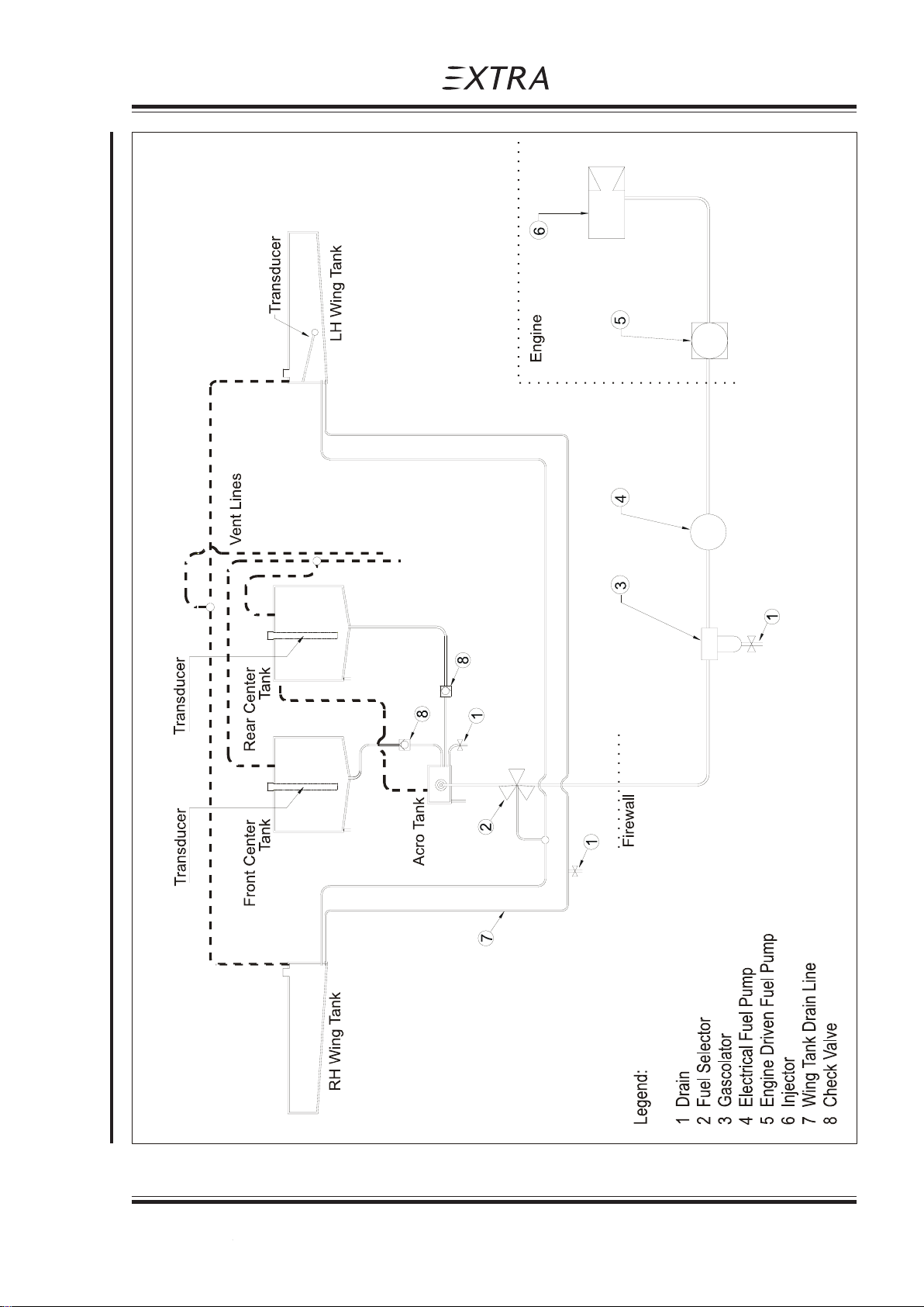
Pilot´s Operating Handbook
EXTRA 300/SC
Description and Operation of Aircraft and Systems
Section 7
Figure 7-3: Fuel system
Page Date: 29. February 2008 7 - 11
Page Date: 12. February 2010
Page 91

Section 7
Description and Operation of Aircraft and Systems
When ACRO & CENTER TANKS are selected in flight the tank with the higher fuel
level will empty slightly faster than the other.
When both front and rear center tank indications read "ZERO" the remaining fuel in
the acro tank is less than 9 liters (2.37 US Gal.). 2.5 liters (0.66 US Gal.) of this
remaining fuel are not usable.
The center tanks are made from aluminum and are covered by a separate shell made of
GRP for safety. The space between the aluminum tank and the safety GRP shell is vented
and drained overboard. In case of a crack in the aluminium tank, the leaking fuel is dumped
overboard, while the GRP shell will indicate the location of the leak by coloring blue.
Wing tank system:
The root section of each wing in front of main spars forms an integral fuel tank providing two
interconnected tanks with 120 liters (31,7 US GAL.) total capacity. Each side of the wing has
a 2" diameter filler cap for gravity refueling. The caps are labelled "FUEL AVGAS 100/
100LL".The wing tank can be completely emptied in flight .
Pilot´s Operating Handbook
EXTRA 300/SC
NOTES
NOTE
The wing tank must be empty when flying aerobatic maneuvers.
Adequate venting is provided in each tank by ventilation-tubes.
All ventilation and drain lines merge at the right side of the fuselage and end on the upper
main gear leg.
In addition to the engine driven fuel pump an electrically driven auxiliary fuel pump (boost
pump) with by-pass and having sufficient capacity to feed the engine at take-off power is
fitted as a safety device against failure of the engine-driven pump. The boost pump switch is
located on the instrument panel.
A fuel filter with drain is installed between the fuel selector valve and the boost pump.
Separate drains are located at the lowest point of each tank system: the acro & center tanks
drain on the right underside and the wing tank drain on the left underside of the fuselage just
behind the main gear attachment.
Normal float type transducers and electrically operated fuel indicators are used.
Alternatively, variable capacitance type transducers for the center tanks are used.
7 - 12 Page Date: 29. February 2008
Page Date: 10. January 2011
Page 92

Pilot´s Operating Handbook
EXTRA 300/SC
7.12 ELECTRICAL SYSTEM
The electrical power generation system (refer to fig. 7-4) consists of a 12 V alternator with
rectifier and transistor voltage regulator. The alternator is mounted on and driven by the
engine.
The field current is controlled by the voltage regulator to give a nominal output of 13,8 V
under all load conditions.
Circuit protection against over-voltage is provided by the voltage regulator. If an over-voltage
occurs the regulator causes the 2 amp. OV PROTECT circuit breaker to trip. In this case a
relais disconnects the alternator from the aircraft system. This is indicated by the lit
alternator warning light. Consider that in flight in this case the battery is the only power
source.
The maximum load taken from the alternator is 8.4 Amps (@2700 RPM).
A 12 V leak proof battery is connected across the alternator output to stabilize the supply
and to maintain all essential services in the event of an alternator failure and when the
engine is not operating. The battery is mounted behind the firewall.
The master-switch is located on the instrument panel.
The system is equipped with an ampere meter, which allows monitoring the battery state of
charge.
All electrical circuits are protected by circuit breakers or fuses. All circuit breakers are
located on the instrument panel and are easily accessible to the pilot during flight.
The electrical system is adequately suppressed to ensure satisfactory operation of the radio
equipment.
All wires, switches, circuit breakers etc. are manufactured to related aeronautical
specifications.
Description and Operation of Aircraft and Systems
Section 7
7.13 CABIN ENVIRONMENT CONTROL
A ventilation system in the canopy is provided for the supply of fresh air to the cabin. The
bad weather window is equipped with a ventilation scoop to provide supply of fresh air to the
cabin. Additionally, to the right and left side of the cockpit an eyeball-type adjustable vent is
installed.
Page Date: 29. February 2008 7 - 13
Page Date: 10. January 2011
Page 93
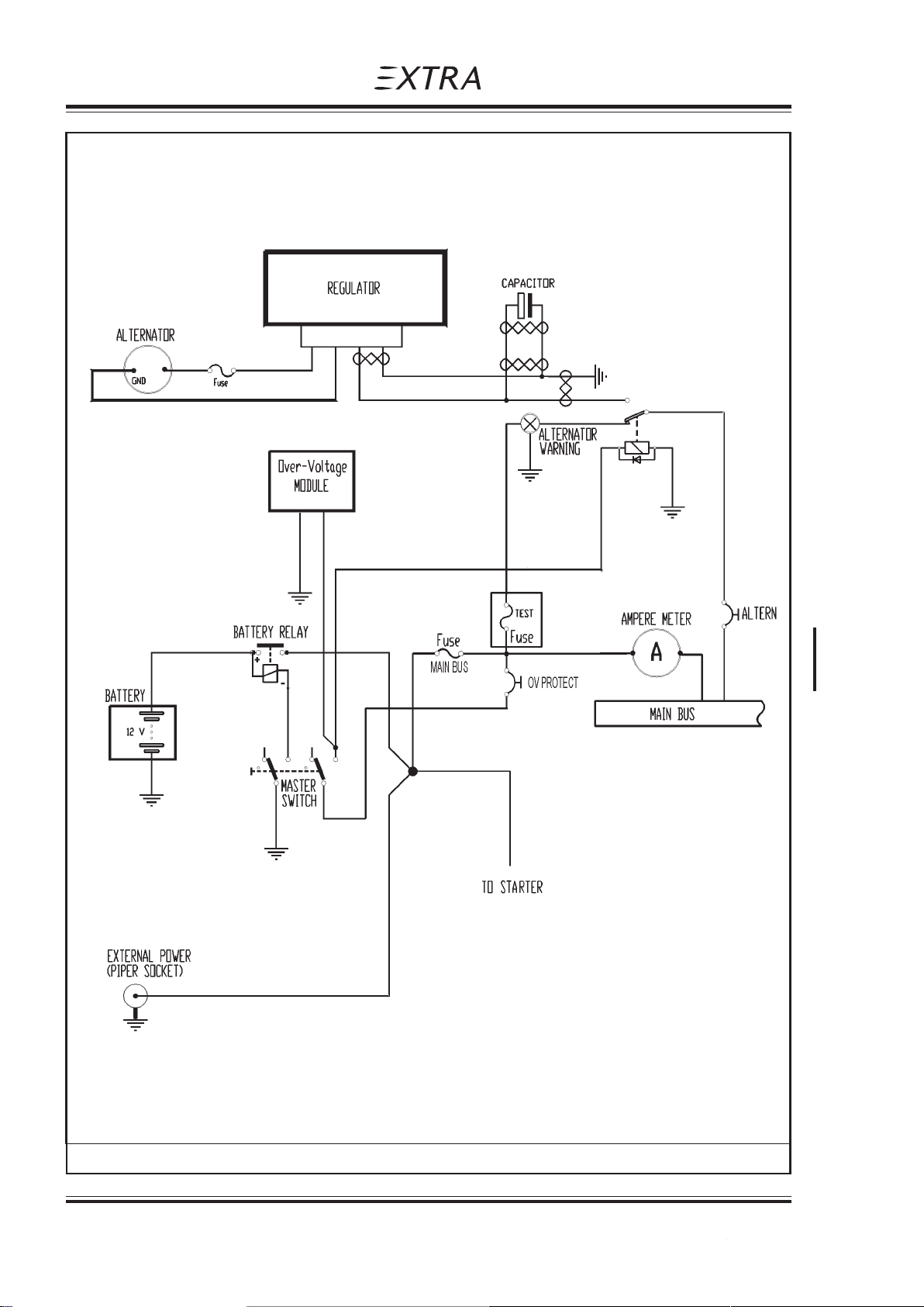
Section 7
Description and Operation of Aircraft and Systems
Pilot´s Operating Handbook
EXTRA 300/SC
Figure 7-4, Sheet 1: Electrical system, power generation
7 - 14 Page Date: 29. February 2008
Page Date: 10. January 2011
Page 94
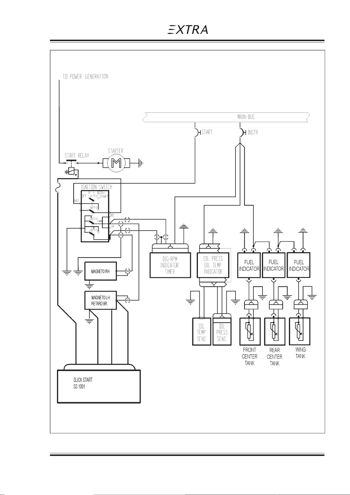
Pilot´s Operating Handbook
EXTRA 300/SC
*
Description and Operation of Aircraft and Systems
Section 7
* fuse only used on SN SC003, SC004 and SC005
Figure 7-4, Sheet 2: Electrical system, engine and instruments
Page Date: 29. February 2008 7 - 15
Page 95
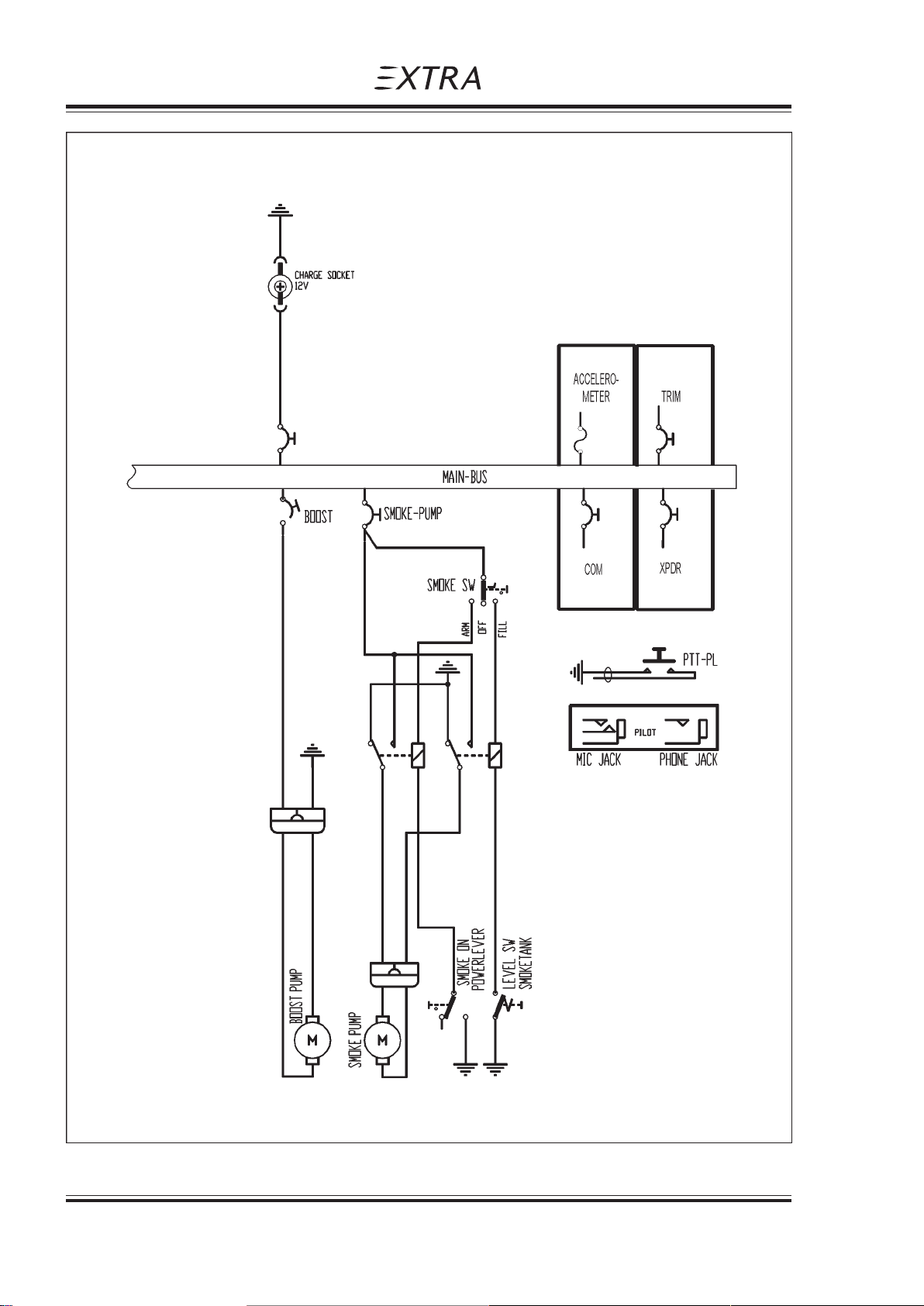
Section 7
Description and Operation of Aircraft and Systems
Pilot´s Operating Handbook
EXTRA 300/SC
Figure 7-4, Sheet 3: Electrical system, furhter equipment
7 - 16 Page Date: 29. February 2008
Page 96

Pilot´s Operating Handbook
EXTRA 300/SC
Handling, Servicing and Maintenance
Section 8
SECTION 8
HANDLING, SERVICING AND MAINTENANCE
Table of Contents
Paragraph Page
SECTION 8 HANDLING , SER VICING
8.1 INTRODUCTION................................................................................................................. 8-3
8.2 AIRPLANE INSPECTION PERIODS................................................................................... 8-3
8.3 PILOT CONDUCTED PREVENTIVE MAINTENANCE ....................................................... 8-3
8.4 AL TERA TIONS OR REPAIR ............................................................................................... 8-3
8.5 SERVICING......................................................................................................................... 8-3
8.6 GROUND HANDLING......................................................................................................... 8-4
Page Date: 29. February 2008 8 - 1
Page 97

Section 8
Handling, Servicing and Maintenance
Pilot´s Operating Handbook
EXTRA 300/SC
Left blank intentionally
8 - 2 Page Date: 29. February 2008
Page 98

Pilot´s Operating Handbook
EXTRA 300/SC
HANDLING, SERVICING AND MAINTENANCE
8.1 INTRODUCTION
a) The airplane owner should establish contact with the dealer or certified service station for
service and information.
b) All correspondence regarding the airplane must include its serial number which is
stamped on a plate on the L/H rear part of the fuselage.
c) A service manual with revision service may be procured from the manufacturer.
8.2 AIRPLANE INSPECTION PERIODS
Handling, Servicing and Maintenance
Section 8
SECTION 8
As required by national operating rules all airplanes must pass a complete annual inspection
every twelve calendar months. In addition to the annual inspection airplanes must pass a
complete inspection after every 100 flights hours with a minor check after
50 and 25 hours.
The Airworthiness Authority may require other inspections by the issuance of airworthiness
directives applicable to the aircraft, engine, propeller and components. The owner is
responsible for compliance with all applicable airworthiness directives and periodical
inspections.
8.3 PILOT CONDUCTED PREVENTIVE MAINTENANCE
Pilots operating the airplane should refer to the regulations of the country of certification for
information of preventive maintenance that may be performed by pilots. All other
maintenance required on the airplane is to be accomplished by appropriately licensed
personnel. Airplane dealer should be contacted for further information
Preventive maintenance should be accomplished with an appropriate service manual.
8.4 ALTERATIONS OR REPAIR
Alterations or repairs of the airplane must be accomplished by licensed personel.
8.5 SERVICING
In addition to the airplane inspection periods (8.2) information for servicing the aircraft with
proper oil and fuel is covered in Section 2 (Limitations) and Section 7 (Descriptions and
Operation).
Page Date: 29. February 2008 8 - 3
Page 99

Section 8
Handling, Servicing and Maintenance
8.6 GROUND HANDLING
a) Due to its low weight and the free swiveling tail wheel two persons can easily move the
airplane by hand.
b) If the aircraft is parked in the open, it must be protected against the effects of weather,
the degree of protection depending on severity of the weather conditions and the expected
duration of the parking period. When the airplane is parked in good weather conditions for
less than a half day park the aircraft headed into the wind and place wheel chocks at the
main wheels.
Pilot´s Operating Handbook
EXTRA 300/SC
8 - 4 Page Date: 29. February 2008
Page 100

Pilot´s Operating Handbook
EXTRA 300/SC
Section 9
Supplements
SECTION 9
SUPPLEMENTS
Doc-No. EA-0C701.1
Table of Contents
Section Pages
9 Supplements ............................................................................................................ 4 p.
901 Steerable Tail Wheel ............................................................................................... 4 p.
902 Smoke System......................................................................................................... 8 p.
903 BECKER ATC 4401 Transponder ........................................................................... 8 p.
904 BECKER BXP 6401 Transponder ........................................................................... 10 p.
905 Digital RPM Indicator .............................................................................................. 6 p.
906 Accelerometer TL 3424_EXT .................................................................................. 6 p.
907 External Power ........................................................................................................ 4 p.
908 ARTEX ME-406 ELT ................................................................................................. 8 p.
909 Electric Pedal Adjustment ...................................................................................... 4 p.
SECTION 9 SUPPLEMENTS
9 SUPPLEMENTS ....................................................................................................................3
Page Date: 29. February 2008 9 - 1
Page Date: 12. February 2010
 Loading...