

Exterity AvediaStream e2535, AvediaStream e3635, AvediaStream e2655, AvediaStream e3655 Administrator's Manual
AvediaStream® e2635/55 and
e3635/55 Encoders V1.1
Administrator’s Guide

AvediaStream e2535/e3635 and e2655/e3655 Encoders V1.1
Notices
© Exterity Limited 2003-2012
This document contains information that is
protected by copyright. Reproduction,
adaptation, or translation without prior
permission is prohibited, except as under the
copyright laws.
Document Reference
1300-0055-0001
Edition
1.1 Issue (July 2012)
Printed in UK
Exterity Limited
Ridge Way
Hillend Industrial Park
Dalgety Bay,
Fife,
KY11 9JD
Scotland, UK
http://www.exterity.com
Products Covered By This Guide
AvediaStream e2635 (avstr-e2635)
AvediaStream e2655 (avstr-e2655)
Disclaimer
The information contained in this document is
subject to change without notice.
EXTERITY LIMITED MAKES NO WARRANTY
OF ANY KIND WITH REGARD TO THIS
MATERIAL, INCLUDING, BUT NOT LIMITED
TO, THE IMPLIED WARRANTIES OF
MERCHANTABILITY AND FITNESS FOR A
PARTICULAR PURPOSE. Exterity Limited
shall not be liable for errors contained herein or
for incidental or consequential damages in
connection with the furnishing, performance, or
use of this material.
Warranty
A copy of the specific warranty terms applicable
to your Exterity products and replacement parts
can be obtained from Exterity. To request more
information or parts, email
support@exterity.com
Safety Notices
Before installing and operating these products,
please read the safety information in this
manual.
AvediaStream e3635 (avstr-e3635)
AvediaStream e3655 (avstr-e3655)
For more detailed information refer to Scope on
page 6.
Trademarks
The Exterity building IPTV logo, AvediaStream,
AvediaServer, AvediaCentre, AvediaPlayer,
prodaptor, in-Socket technology, isocket, and
digital simplicity are trademarks or registered
trademarks of Exterity Limited.
Microsoft®, Windows®, and Windows Media
Player® are U.S. registered trademarks of
Microsoft Corporation.
Dolby and the double-D symbol are trademarks
of Dolby Laboratories.
HDMI®, the HDMI logo, and High-Definition
Multimedia Interface are trademarks or
registered trademarks of HDMI Licensing, LLC
in the United States and/or other countries.
All other trademarks are the property of their
respective owners. All rights reserved.
2 Administrator’s Guide

AvediaStream e2535/e3635 and e2655/e3655 Encoders V1.1
Contents
USA and Canada ......................................................................................................................... 4
EU and Others ............................................................................................................................. 5
Summary ..................................................................................................................................... 6
Audience ...................................................................................................................................... 6
Scope ........................................................................................................................................... 6
Associated documentation .......................................................................................................... 6
How this Manual is Organised ..................................................................................................... 9
1 Getting Started ................................................................................................................................ 10
2 Physical Interfaces .......................................................................................................................... 12
Chassis Interface ....................................................................................................................... 12
Encoder Rear Panel Interfaces ................................................................................................. 13
3 Management Interfaces .................................................................................................................. 17
Web Management Interface ...................................................................................................... 17
Admin Interface .......................................................................................................................... 19
AvediaServer Director ................................................................................................................ 19
4 General Device Management ......................................................................................................... 21
About The Encoder .................................................................................................................... 21
Device Naming .......................................................................................................................... 22
Network Configuration ............................................................................................................... 22
Authentication ............................................................................................................................ 24
Maintenance .............................................................................................................................. 25
Logging ...................................................................................................................................... 28
5 Admin Interface ............................................................................................................................... 30
Admin interface pages ............................................................................................................... 30
6 Encoding and Streaming ................................................................................................................ 32
Audio/Video Input – AvediaStream e2635/e3635 ..................................................................... 32
Audio/Video Input – AvediaStream e2655 /e3655 .................................................................... 36
Encoding .................................................................................................................................... 38
Channel Announcements .......................................................................................................... 47
Stream Properties ...................................................................................................................... 49
7 Status Monitoring ............................................................................................................................ 52
Status Page Information ............................................................................................................ 52
Network Statistics ...................................................................................................................... 53
8 Troubleshooting .............................................................................................................................. 54
APPENDIX A Serial Interface Connection ........................................................................................ 55
APPENDIX B Support and Contact Information................................................................................ 57
Administrator’s Guide 3

AvediaStream e2535/e3635 and e2655/e3655 Encoders V1.1
The lightning flash with arrowhead symbol within an equilateral
triangle, is intended to alert the user to the presence of
uninsulated "dangerous voltage" within the product's enclosure
that may be of sufficient magnitude to constitute a risk of
electric shock to persons.
The exclamation point within an equilateral triangle is intended
to alert the user to the presence of important operating and
maintenance (servicing) instructions in the literature
accompanying the product.
Important Safety Instructions
There are no instructions specifically for service personnel in this document. There are no user
serviceable parts inside any Exterity product. To prevent electric shock or fire hazard, do not
remove cover. Refer service to qualified service personnel.
This chapter contains important safety information. If you are unsure about any of the
information in the section, please contact Exterity.
USA and Canada
1. Read these instructions.
2. Keep these instructions.
3. Heed all warnings.
4. Follow all instructions.
5. Do not use this apparatus near water.
6. Clean only with dry cloth.
7. Do not block any ventilation openings. Install in accordance with the instructions contained
in this manual.
8. Do not install near any heat sources such as radiators, heat registers, stoves, or other
apparatus (including amplifiers) that produce heat.
9. Do not defeat the safety purpose of the polarized or grounding-type plug. A polarized plug
has two blades with one wider than the other. A grounding type plug has two blades and a
third grounding prong. The wide blade or the third prong are provided for your safety. If the
provided plug does not fit into your outlet, consult an electrician for replacement of the
obsolete outlet.
10. Protect the power cord from being walked on or pinched particularly at plugs, convenience
receptacles, and the point where they exit from the apparatus.
11. Only use attachments/accessories specified by the manufacturer.
12. Use only with the cart, stand, tripod, bracket, or table specified by the manufacturer, or
sold with the apparatus. When a cart is used, use caution when moving the cart/apparatus
combination to avoid injury from tip-over.
4 Administrator’s Guide

13. Unplug this apparatus during lightning storms or when unused for long periods of time.
14. Refer all servicing to qualified service personnel. Servicing is required when the apparatus
has been damaged in any way, such as power-supply cord or plug is damaged, liquid has
been spilled or objects have fallen into the apparatus, the apparatus has been exposed to
rain or moisture, does not operate normally, or has been dropped.
15. Do not expose this apparatus to dripping or splashing and ensure that no objects filled with
liquids, such as vases, are placed on the apparatus.
16. To completely disconnect this apparatus from the AC Mains, disconnect the power supply
cord plug from the AC receptacle.
17. The mains plug of the power supply cord shall remain readily operable.
WARNING: To reduce the risk of fire or electric shock, do not expose this apparatus to rain or
moisture.
EU and Others
Do not proceed beyond a WARNING! notice until you have understood the hazardous
conditions and have taken appropriate steps.
Safety Information
WARNING! There are no user serviceable parts inside any Exterity product. To prevent
electric shock or fire hazard, do not remove cover. Refer service to qualified service personnel.
AvediaStream e2535/e3635 and e2655/e3655 Encoders V1.1
WARNING! For 230/240 volt operation, be sure to use a harmonised grounded 3 conductor
cord, rated 6 Amp minimum. Use a suitable cord for connection to the equipment and
terminating in an IEC approved plug.
This equipment relies upon a safety earth for operation, ensure that you always use a power
cord with appropriate earth and that the inlet to which is inserted also has the appropriate
earth. If in any doubt about the earth provision in your building consult a qualified electrician
WARNING! Use only the dedicated power supply or cord supplied for your device.
WARNING! The Exterity products use ventilation holes for cooling. None of the ventilation
holes should be blocked. Keep all materials at least 5cm away from all the ventilation holes.
WARNING! Do not expose the product to any rain or moisture.
WARNING! Do not use the product near a naked flame e.g. a candle.
WARNING! The operating conditions of the product should be 0°C-40°C with a Relative
Humidity of 5 – 95%.The product should not be operated outside of these conditions.
There are no user-serviceable parts inside these products. Any servicing, adjustment,
maintenance, or repair must only be performed by service-trained personnel.
Administrator’s Guide 5
AvediaStream e2535/e3635 and e2655/e3655 Encoders V1.1
Manual
Reference Number
AvediaStream Installation Guide
1300-0018-0001
AvediaServer Director application
1300-0052-0001
Summary
This manual explains how to set up, use and manage the AvediaStream e2635/55 and
e3635/55 products, commonly referred to as “encoders”. Encoders are network devices that
accept a signal from an AV device, for example, a DVD player or set-top box, and output it as
an MPEG transport stream over an IP network.
Audience
This manual is intended for use by systems integrators or systems administrators who are
installing and setting up Exterity products. The manual assumes that readers are familiar with
installing and configuring network-based products.
Scope
This edition of the manual refers to version 1.1 of firmware for the AvediaStream e2635,
e2655, e3635, and 3655 encoders.
About this Manual
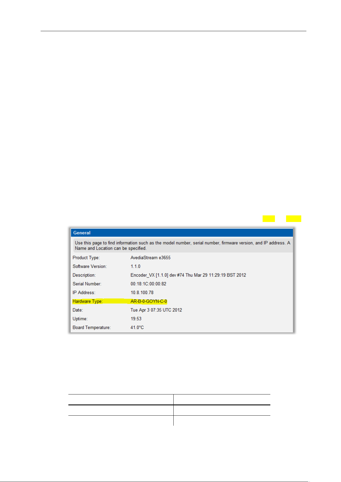
The relevant hardware information is shown as part of the character string displayed in the
Hardware Type line on the General Page of the AvediaStream web interface as shown in
Figure 1. In the example shown, the AvediaStream e3655 lists hardware type AR-B –x –GOYN.
Figure 1 Hardware Type String
Associated documentation
This manual should be used in conjunction with the manuals listed in Table 1.
6 Administrator’s Guide
Table 1 Associated Documentation

Terms and Definitions
The following terms and definitions are used in this document:
AC-3 – An audio compression scheme, also known as Dolby Digital.
AES – A standard for carrying digital audio.
Board – The printed circuit board within the unit.
Composite video – A type of analogue video signal where the luminance, chrominance and
sync signals are all carried on a single cable. This is often referred to as CVBS.
DHCP – Dynamic Host Configuration Protocol, a protocol used to allocate IP addresses to
devices on an IP network.
ED – Enhanced Definition video, 525p 60Hz and 625p 50Hz.
H.264 - A standard for video compression, also known as MPEG-4 Part 10 and MPEG-4 AVC
(Advanced Video Coding).
HD – High Definition video, 720p, 1080i and 1080p (1080p capability only on specified
products).
HD AV – A digital input interface for connection to devices equipped with DVI (DVI-to-HDMI
adaptor required) and HDMI connections.
HDCP – High-bandwidth Digital Content Protection is designed to prevent copying of digital
audio and video content passing across Digital Visual Interface (DVI) and High-Definition
Multimedia Interface (HDMI) connections.
HDMI™ - High-Definition Multimedia Interface, a compact interface for transmission of
uncompressed digital audio and video content.
IGMP – Internet Group Management Protocol, a protocol used to manage multicast traffic on
an IP network.
Input – Physical interface on Exterity equipment that receives Audio/Video from a source.
IP – Internet Protocol, a protocol used for communicating data across a network using the
Internet Protocol Suite, also referred to as TCP/IP.
IP TOS – The Type of Service (TOS) field is a six-bit Differentiated Services Code Point
(DSCP) field and a two-bit Explicit Congestion Notification field.
MPEG – A family of compression methodologies for audio and video.
MPEG Transport Stream - A communications protocol enabling multiplexing of digital audio,
video and data which is specified in MPEG-2 Part 1, Systems (ISO/IEC standard 13818-1).
NTP – Network Time Protocol, a protocol for synchronizing the clocks of computer systems.
RGBHV – Is a Red (R), Green (G), Blue (B) component analogue video signal with horizontal
(H) and vertical (V) synchronisation, all on separate lines. It is most commonly used in the
VGA connection for computer monitors.
RTP - Real-time Transport Protocol, a protocol used to carry real time data on an IP network.
SAP – Session Announcement Protocol, a protocol used to advertise the presence of
multicast sessions on an IP network.
SD – Standard Definition video, 525i 60Hz and 625i 50Hz.
SDI - Serial Digital Interface (SDI), a high speed serial interface that carries uncompressed
video with the option of embedded audio. It is specified as SMPTE 259M
(270MB/s SD-SDI), SMPTE 292M (1.485Gbit/s HD-SDI), and SMPTE 424M (2.97Gbits/s 3GSDI).
Source – A device that can provide an Audio/Video input to the encoder, for example, a DVD
player.
SVC – Scalable Video Coding, part of the H.264/MPEG-4 AVC video compression standard.
Telnet – Telnet is a network protocol that enables one computer to communicate with another
over an IP network.
TFTP – Trivial File Transfer Protocol, a simple file transfer protocol used on IP networks.
UDP – User Datagram Protocol, a transport protocol in the TCP/IP suite, which provides a
connectionless transport mechanism with low overhead.
Unit – Exterity product, for example, an AvediaStream e36x unit containing a printed circuit
board.
AvediaStream e2535/e3635 and e2655/e3655 Encoders V1.1
Administrator’s Guide 7

AvediaStream e2535/e3635 and e2655/e3655 Encoders V1.1
YPbPr – A type of component analogue video signal consisting of a colourless component
(luminance), combined with two colour-carrying components (chrominance). This is commonly
referred to simply as “component”.
8 Administrator’s Guide

AvediaStream e2535/e3635 and e2655/e3655 Encoders V1.1
Chapter 1 – Getting Started
This chapter describes how to get the
encoder up and running.
Chapter 2 – Physical Interfaces
This chapter describes how to connect your
AV equipment to the encoder.
Chapter 3 – Management Interfaces
This chapter describes the management
interfaces you can use to manage the
encoder: the IPTV Manager, Web
Management Interface and admin interface.
Chapter 4 - General Device Management
This chapter describes general configuration
of the encoder. For example, IP address
configuration and the firmware upgrade
procedure are explained here.
Chapter 5 – Admin Interface
This chapter describes how to configure the
encoder using the serial Admin Interface.
Chapter 6 - Encoding and Streaming
This chapter explains how to configure the
encoder to take accept the input of the AV
source and convert this into an IPTV stream.
Chapter 7 - Status Monitoring
This chapter explains how to check the
operating status of the encoder.
Chapter 8 – Troubleshooting
This section provides troubleshooting
information if you are having problems with
the encoder.
How this Manual is Organised
This manual is organised as follows:
Administrator’s Guide 9

AvediaStream e2535/e3635 and e2655/e3655 Encoders V1.1
1 Getting Started
AvediaStream Encoders create a single IPTV stream on your building, campus or
metropolitan-area IP network from the output of various video devices. You can use them to
distribute the output from a variety of Standard Definition and High Definition AV devices such
as video cameras, DVD players, set-top boxes and professional SDI feeds.
The AvediaStream e26xx/36xx encoders accept SD and HD content inputs (up to 1080p
50/60Hz). The encoders allow scaling of both resolution and frame rate in the output stream.
The e36xx encoders allow scaling of any input to any output resolution and frame rate up to
1080i 50/60Hz. The AvediaStream e26xx encoders allow up to 576i in the output transport
stream.
The following procedures must be performed for the encoder to perform correctly. These
procedures are summarised in this section:
1. Connecting the AV Source
Before the encoder can stream audio/video on the network, an AV source must be connected.
See Physical Interfaces on page 12 for details on how to connect your AV equipment to the
encoder.
2. Connecting to the Network
Connect the encoder to the network.
For more information, see the AvediaStream Installation Guide.
3. Powering the Encoder
Connect the encoder to a power source.
For more information, see the AvediaStream Installation Guide.
4. Configuring the IP Address of the Encoder
By default, the encoder requires a DHCP Server to be available on the network to assign it an
IP address.
There are two methods of assigning a static IP address to the encoder, if required:
● Use the serial Admin Interface to configure the IP address. For more information refer to
Admin Interface on page 19.
● Temporarily set up a DHCP server on an isolated network. Once an IP address is
assigned to the encoder, you can configure a static IP address using the Web
Management Interface. For more information refer to Network Configuration on page 22.
Allocating a static IP address for the encoder allows continued operation without a DHCP
Server.
5. Naming the Encoder
Provide a name for the encoder so you can easily identify it in the future. This can be done
using the AvediaServer Director application (shown in Figure 8 on page 19) I) or the Web
Interface General Page (shown in Figure 9 on page 21).
6. Configuring Audio/Video Input
The device starts encoding and streaming automatically when an appropriate AV source is
connected. It may be necessary to configure the type of video source connected. Refer to
Encoding and Streaming on page 32 for more information.
10 Administrator’s Guide

AvediaStream e2635/e3635 and e2655/e3655 Encoders V1.1
7. Configuring Encoding Options
The device starts encoding automatically when an appropriate source is connected. Some
aspects of the encoding can be configured if required. The encoder starts streaming
(transmitting an MPEG transport stream on the IP network) automatically when an appropriate
source is connected. Some aspects of the stream can be configured if required. For more
information refer to Encoding and Streaming on page 32 and to Stream Properties on page 47.
8. Configuring Test Patterns and Overlays
Specify solid colours/test patterns and/or logo and text overlays if you want to either carry out
system testing using common test patterns or add logos and text overlays to be displayed
continuously or when no signals are present at the input of the encoder.
For more information refer to Test Pattern on page 42.
9. Configuring Channel Announcements
The encoder uses SAP (Session Announcement Protocol) to announce its stream (channel) to
receiving devices. Included in the announcements are the name of the channel and the
multicast address and port on which the stream is sent. This is done automatically once the
encoder is up and running.
You can configure channel announcements to suit your requirements. For more information
refer to Channel Announcements on page 47.
10. Checking Status
You can check the operating status of the encoder and that the encoder is transmitting data at
the rate expected by the streaming settings. For more information refer to Status Monitoring on
page 52.
Administrator’s Guide 11

AvediaStream e2535/e3635 and e2655/e3655 Encoders V1.1
Pattern (approx rate)
Description
Twice a Second
Running Power on Self Tests
Solid On
Booting operating System, takes
approximately 10-20 seconds
Once a second
Heartbeat indicates unit is running normally
Alternatively < 1 sec, > 10 secs
Upgrading
2 Physical Interfaces
AvediaStream e26xx and e36xx encoders can operate in any of the following chassis:
● AvediaStream c1101
● AvediaStream c1103
● AvediaStream c1110
The encoder has AV interfaces on its rear panel, while its edge connector enables it to access
network and admin ports via the chassis front panel.
Caution: Take care not to touch the edge connector as static electricity might damage the
product. Handle by the enclosure only and insert as soon as possible into the chassis.
Chassis Interface
The Encoder module provides the following interfaces over its edge connector to the chassis:
● Ethernet interface (10/100Mbps)
● Admin Interface
● Status LEDs
● Power supply
The actual physical interfaces can be found on the chassis front panel. Please refer to the
relevant AvediaStream Installation Guide for further details.
Heartbeat LED
The heartbeat LED (marked H/B) on the AvediaStream front panel provides an indication of
the current state of the unit without using any of the management interfaces. The LED
behaviour is described in Table 2 Heartbeat LED Patterns.
Table 2 Heartbeat LED Patterns
12 Administrator’s Guide

AvediaStream e2635/e3635 and e2655/e3655 Encoders V1.1
Video Inputs
e2635/e3635
e2655/e3655
HD Component
●
SD Component
●
HD AV
●
RGBHV
●
SD-SDI (SMPTE 259M)
●
HD-SDI (SMPTE 292M)
●
3G-SDI (SMPTE 424M)
●
Audio Inputs
Unbalanced
●
S/PDIF
●
●
HD AV embedded
Audio1
●
SDI Embedded Audio
●
●
IR Out Socket
●
Encoder Rear Panel Interfaces
The AvediaStream e26xx and e36xx encoders support the following inputs and outputs:
Table 3 Encoder Rear Panel Interfaces
1HD AV Audio is only available when HD AV video selected.
Administrator’s Guide 13
AvediaStream e2535/e3635 and e2655/e3655 Encoders V1.1
AvediaStream e2635/e3635 Interface
The AvediaStream e2635 and e3635 encoders provide video and audio inputs as shown in
Figure 2.
Figure 2 AvediaStream e3635 Encoder – Rear Panel
Video Inputs
The e2635 and e3635 support the following video input types:
● HDMI (HD AV) with audio
● VGA (RGBHV)
● YPbPr
Connect an HDMI source to the encoder using a standard HDMI Type A plug connector to
connect to the HD AV input.
Connect an RGBHV source such as a VGA-equipped PC or signage equipment using a
standard VGA monitor cable (fitted with 3-row 15-pin DE-15 plugs) to connect to the RGBHV
input.
Connect a YPbPr component source using the supplied VGA-to-phono adaptor (female) to
connect to the RGBHV input.
Note: High-bandwidth Digital Content Protection (HDCP) is not supported on the HD AV
interface.
Note: You can use an HDMI-to-DVI converter/cable to connect a DVI source to the HD AV
input.
Audio Inputs
● Unbalanced audio - Inputs marked Left and Right, connection using RCA (Phono) cables.
● S/PDIF – Input marked SPDIF, connection using an RCA (Phono) cable supporting
uncompressed (48kHz supported) or compressed (AAC) inputs.
● HD AV audio – when HD AV video input is selected.
IR Out Socket
This is intended to control the attached AV device. The associated IR transmitter is supplied
with the unit.
Note: The IR function is not available with this firmware release.
14 Administrator’s Guide

AvediaStream e2635/e3635 and e2655/e3655 Encoders V1.1
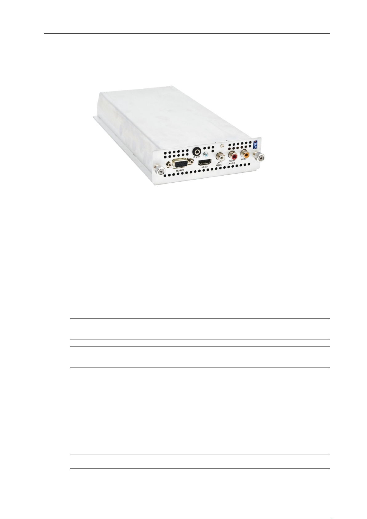
AvediaStream e2655/e3655 Interface
The AvediaStream e2655 and e3655 encoders provide a Serial Digital Interface video input
with embedded or S/PDIF audio inputs. SDI Loop-through is also available. Connections are
shown in Figure 3 below.
Figure 3 AvediaStream e3655 Encoder – Rear Panel
The AvediaStream e2655 and e3655 offer three physical interfaces:
● Single input BNC (SDI video, SDI video with embedded audio)
● Single output ‘Loop-though’ BNC (No Output, Input loop-through, or Re-clocked Input
Loop-through)
● RCA Phono (SPDIF audio)
This allows you to encode audio from the SDI interface or to use the S/PDIF interface as the
audio source.
Note: The BNC interface is marked with ASI/SDI as this interface is common to the SDI
Encoder and ASI Gateway. The interface is committed to SDI or ASI in the factory and cannot
have its function changed in the field.
The AvediaStream e2655 and e3655 are fitted with 2 LEDs with following functions:
● Left – The Red LED is lit when signal errors are detected on the input signal.
● Right – The Green LED is lit when the encoder detects SDI, HD-SDI or 3G-SDI input
signals.
SDI Interface (IN)
The SDI interface supports SMPTE 259M (270Mbits/s SD-SDI), SMPTE 292M (1.485Gbit/s
HD-SDI) and SMPTE 424M (2.97Gbits/s 3G-SDI). Connect an SD-SDI, HD-SDI, or 3G-SDI
input using a BNC connector.
The following resolutions and frame rates are supported:
● 525i 60Hz and 625i 50Hz
● 720p 50Hz/59.94Hz/60Hz
● 1080i 50Hz/59.94Hz/60Hz
● 1080p 23.98Hz/24Hz/50Hz/59.94Hz/60Hz
Administrator’s Guide 15

AvediaStream e2535/e3635 and e2655/e3655 Encoders V1.1
SDI Interface (OUT)
The SDI (OUT) interface is a loop-through interface to enable you to connect the same SDI
input to another device.
Connect using a BNC connector.
This output is disabled by default, and can be configured via the web interface Input page.
Caution: Do not connect the output interface to any other output interface as this may damage
the unit.
Audio Inputs
● Embedded SDI stereo audio (stereo pair selectable from one of 8 pairs embedded within
the SDI video stream)
● S/PDIF digital audio (RCA phono) (PCM 48kHz)
This allows you to encode audio from the SDI interface or to use the AES interface as the
audio source
Note: Only 48kHz PCM audio is supported by the encoder. Other detected sample rates result
in “unsupported sampling rate” being displayed on the Status page.
16 Administrator’s Guide
AvediaStream e2635/e3635 and e2655/e3655 Encoders V1.1
3 Management Interfaces
The encoder has four management interfaces, as follows:
● Web Management Interface
● Admin Interface
● AvediaServer Director
Note: Each encoding module in a chassis must be configured independently.
Web Management Interface
You can manage every aspect of the encoder’s functionality using the Web Management
Interface. The Web Management Interface supports Microsoft Internet Explorer and Mozilla
Firefox.
You can display the Web Management Interface using the AvediaServer Director application
as shown on page 19, or by typing the IP address of the encoder directly into your browser.
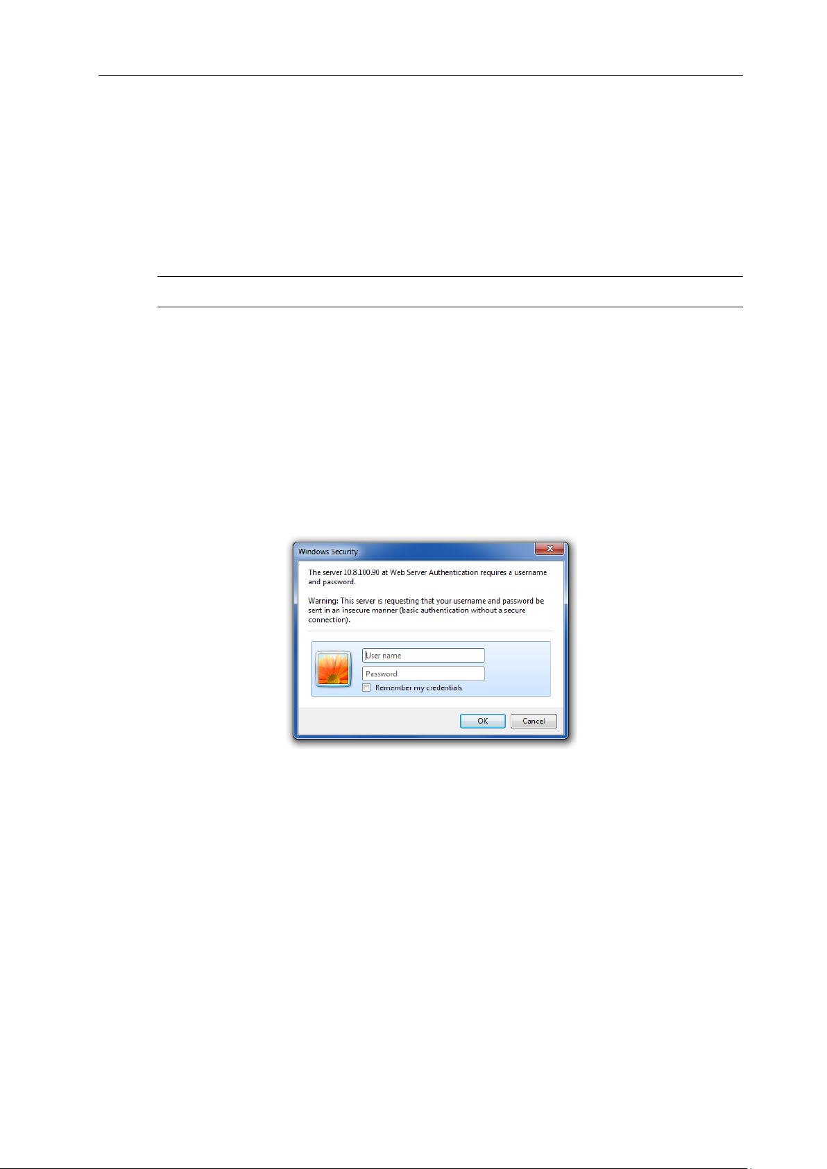
Open the Web Management Interface as follows:
1. When prompted, enter the correct username and password. The default login details are:
Username: admin Password: labrador
Figure 4 Login Window
2. The Web Management Interface opens in your browser, as shown in Figure 5:
Administrator’s Guide 17
AvediaStream e2535/e3635 and e2655/e3655 Encoders V1.1
Figure 5 Web Management Interface
3. Clicking on the encoder name on the left hand side reveals the menu. Use this menu to
navigate through the pages, changing settings as required. Click the Apply button on each
page to save your changes.
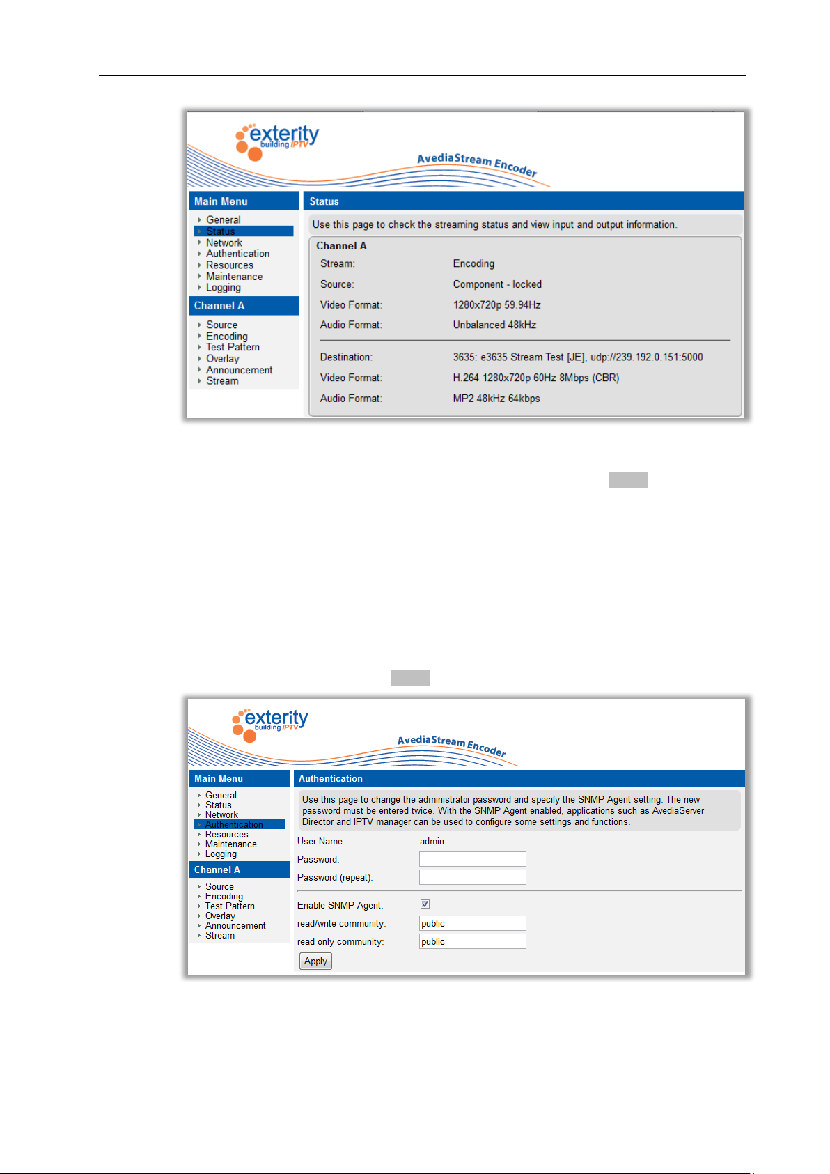
Authentication
You can control access to the web management interface by changing the login details.
To change the admin password:
1. Click on the Authentication page.
2. Specify a password and click the Apply button.
Figure 6 Authentication Page
18 Administrator’s Guide
 Loading...