

Page 1
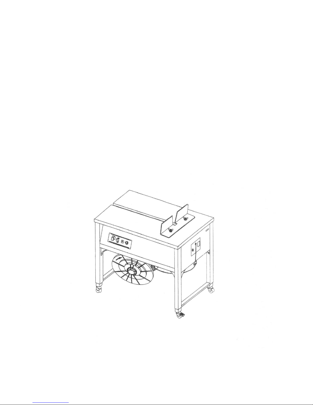
SEMI-AUTOMATIC POLYPROPYLENE
STRAPPING MACHINE
OPERATION & MAINTENANCE MANUAL
Page 2

SAFETY INSTRUCTIONS
Read these safety instructions before operating
or servicing your strapping machine.
1. Before operating the machine , pleases fit over voltage and under voltage
protection to the machine .
2. Wear eye or face, and hand protection. Do not wear loose clothing.
3. Keep hands or other parts of the body out of the strap chute area during operation.
4. The temperature of the heater plate is very high .Do not touch.
5. Do not insert strap while there is not a package on the operation table.
6. Do not replace any safety parts of different specifications.
7. Shut off all electric power after machine operation or servicing machine.
8. Do not use water or steam to clean the machine.
9. Keep this operation manual at your strapping machine . Refer to it often.
Page 3

Specification
NO DESCRIPTION REMARKS
LENGTH 895mm
WIDTH 565mm
1-1
DIMENSION
HEIGHT 740mm
1-2 SEALING METHOD HEAT SEALED
1-3 STRAP WIDTH 5-15mm
1-4 MACHINE TENSION 5-50kg
1-5 NET WEIGHT 100kg
1-6 ACOUSTIC NOISE 65dB(A)
Operating Requirements
NO DESCRIPTION REMARKS
2-1 AMBIENT TEMPERATURE
5~40°C
2-2 RELATIVE HUMIDITY 35~85%RH
2-3 INSTALLATION ALTITUDE 1000M(MAX)
2-4 TRANSPORT/STORAGE TEMPERATURE
-25~55°/70°C
Page 4

TABLE OF CONTENTS
Major components 1
Introduction 1
Exterior Machine 2
Strapping Head 3
Installation 4
Operating Instructions 5
Operating Adjustments 7
Principles of Operation 8
Service Adjustments and Clearances 14
Maintenance 16
Troubleshooting 17
Parts list and Exploded views 18
Electrical schematic 35
Page 5

MAJOR COMPONENTS
In Fig 1.thru 4 the major components of the
machine and the strapping head are
shown in detail.
A detailed description of additional
systems and specific components follows.
STRAP DISPENSER:
The dispenser supplies strapping material
to the strapping head .It is located inside
the cabinet on the lower left-hand side. A
friction brake is provided to limit over-run of
strap.
1. GRIP-The grip holds the lead end of the
strap beneath the anvil while the
remainder of the strap is being tension
around the package.
2.STRAP FEED AND TENSION-Both feed
and tension are achieved by two sets of
gear rollers powered by an electric
motor by means of a drive-belt and
slip-clutch system.
An operator controlled adjustable timer
controls the duration of strap feed. When
the set time for feeding is up, the timer
stops feeding strap. If additional feed is
required beyond that determined by the
timer setting, jog feed will be facilitated
by pushing the “Jog” feed button on the
operator’s control panel.
3.WELDING AND CUT-OFF-Welding of
the strap ends and cutting of the strap
supply are facilitated in this process.
4.PACKAGE REKEASE-After a short
weld-cool period (necessary to avoid
welded ends from popping open) the
package is released.
HOT KNIFE. The “Hot Knife” is
centrally located at the front of the
strapping head Movement of the
knife is controlled by a cam.
ELECTRICAL SYSTEM, An all
electrical system using solid state
technology supplies continual power
supply to the electrical components
within the machine. Using simple to
insert circuit boards provides for
safe and fast maintenance free
operation.
OPERATOR CONTROLS. The
Electrical Control Panel consists of
the “Main Power ON-OFF Switch”
“Feed Length Timer,” “Reset Switch”
and “Feed Length Switch” (Jog
Feed).
INTRODUCTION
This manual contains safety,
operating, and maintenance
instructions for the Semiautomatic
Power Strapping Machine. This
model is designed to strap packages
with plastic strap 1/4 “to 5/8” (6mm
to 15mm) wide. The strap ends are
joined by means of “hot-knife”
welding process.
(Note:) The above mentioned functiond:1,3
and 4 are driven by a cam shaft coupled to
the drive system by means of an
electromagnetic clutch which turns one full
revolution per cycle.
-1-
Page 6
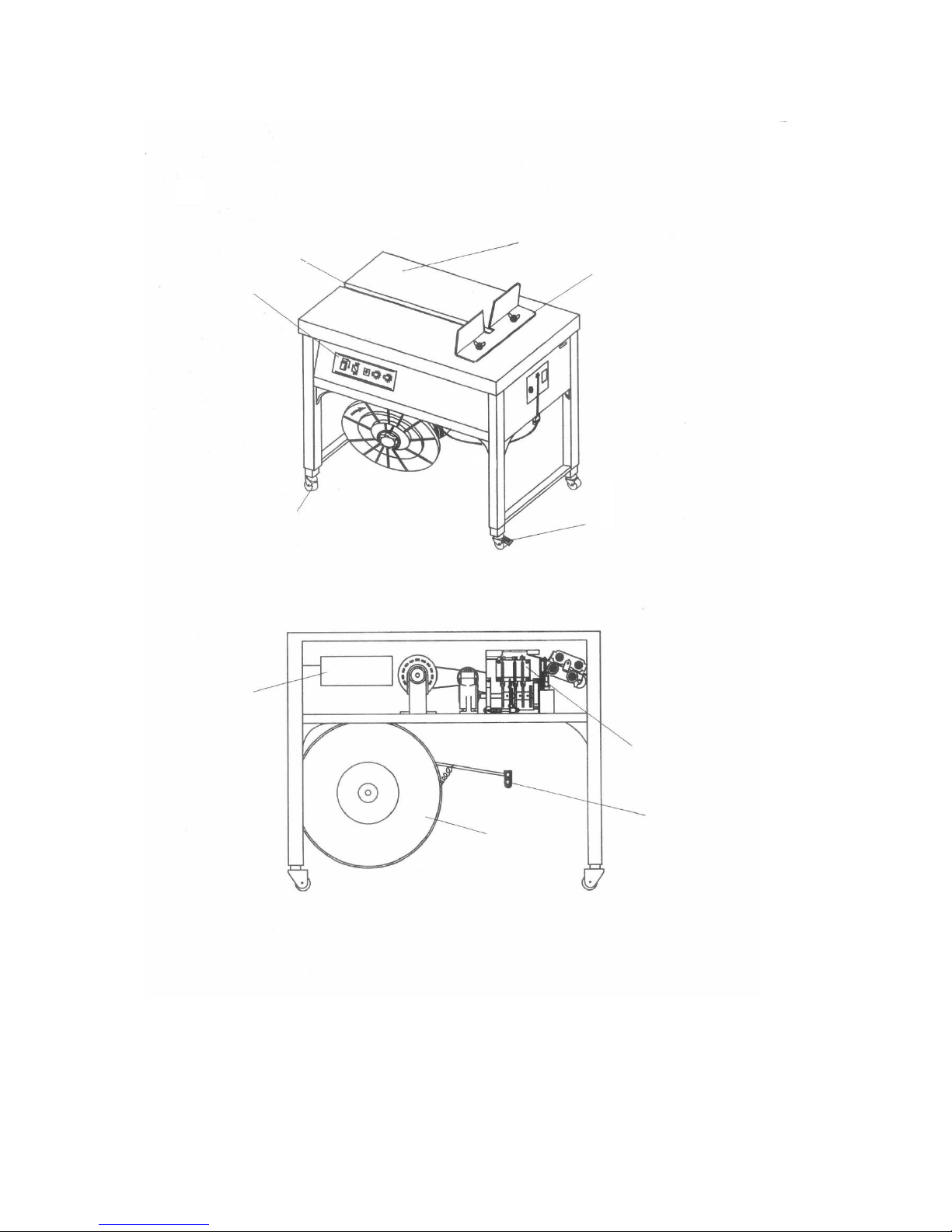
EXTERIOR MACHINE
CONTROL
PANEL
STRAP
CHANNEL
T A BLE T OP
PACKAGE
STOP
FIXED
CASTER
SWIVEL
CASTER
FIGURE1. MAJOR COMPONENTS, EXTERIOR
ELECTRICAL
COMPONENTS
STRAPPING
HEAD
DISPENSER
BRAKE
ASSEMBLY
DISPENSER
FLANGE
FIGURE2. MAJOR COMPONENTS, FRONT VIEW
-2-
Page 7

TENSION
ADJUST
KNOB
MOTOR
FAN
SLIP
CLUTCH
COIL OF
STRAP
ELECTRICAL PANEL DISPENSER BRAKE
FIGURE 3. MAJOR COMPONENTS, TOP VIEW
EXIT
GUIDE
TOP COVER
WELDING
CLAMP
END
GRIPPER
FEED
WHEEL
TENSION
WHEEL
ENTRY
GUIDE
HOLDING
GRIPPER
ELECTROMAGNETIC
CLUTCH
FAN
STRAP
GUIDE
FIGURE 4. MAJOR COMPONENTS, STRAPPING HEAD
TENSIONING
ARM
SOLENOID 1
ANVIL
CAM
HOLDING
GRIPPER
CAM
HOT-KNIFE
CAM
WELDING
CLAMP
CAM
END
GRIPPER
CAM
GEAR
REDUCER
STRAP
ROLLER
-3-
Page 8

INSTALLATION
Installation of the machine, requires that
the machine be uncrated, placed in it’s
proper position and secured in place
once strap of the proper size is loaded
and the power cord is plugged into the
appropriate electrical outlet. Remove the
screw on the top cap of speed reducer
for ventilation.
One set of tools and spare parts is
packed with each machine for use in
making adjustments and for replacement
of parts as needed. Please compare your
supplied tools with the following list:
Micro switch, heavy(LS-1)
Tension spring, short
Tension spring, long
Brake spring
Retainer, top cover holder
TOOLS PARTS
1 Phillips screwdriver(4”)
2 8mm/10mm open end wrench
1 5mm Allen wrench
1 4mm Allen wrench
1 3mm Allen wrench
1 2.5mm Allen wrench
SPARE PARTS
1 104G001
1 2201210020
1 2201011022
1 2201213047
1 4-01000-150
A-895mm
B-740mm
F-565mm
G-400mm
H-230mm
I-110mm
FIGURE 5. INSTALLATION DIMENSIONS AND CLEARANCES
-4-
Page 9
OPERATING INSTRUCTIONS
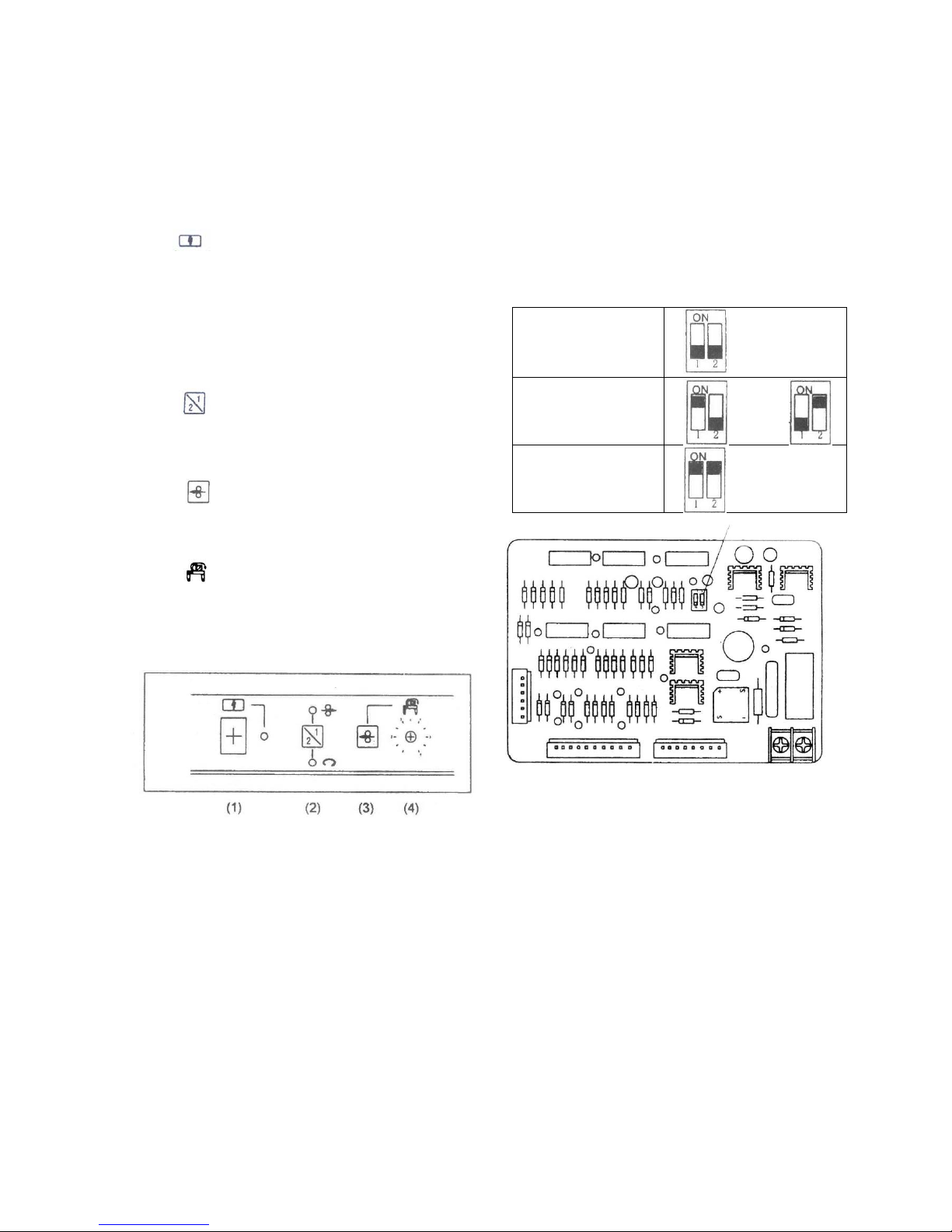
OPERATOR’S CONTROLS
Control Panel. The control panel is located on the
left-hand side of the front panel of the machine.
Refer to Figure 6.
(1)
Power Switch.
Push on the button to make red light glow, which
shows that all electrical circuits and the electric motor
are energized. Then you can operate the machine.
Push down the button, power supple is cut off. If the
machine is stopped incidentally(not in “reset”
mode),push on the button, the machine resets
automatically
(2) Manual Feedback/Reset switch When the
green light is lighted, press the button, you can
feedback PP strap; When the yellow light is lighted,
press the butt ion, you can reset the machine.
(3)
Manual feed
When in “reset” mode (green light is lighted), you can
press the button to feed PP strap manually.
(4) Length Adjustment knob.
Turn knob clockwisely, you can make machine feed
bond longer automatically.
FIGURE6.OPERATOR’SCONTROL PANEL
COOLING TIME ADJUSTMENT
The cooling time adjustment on your machine allows
the user to adjust the cooling time to meet his
strapping qiurement. Please refer to page 34, turn the
knob clockwise, the Cooling time is longer.
MOTOR STOP TIME DIP-SWITCH ADJUSTMENT
The motor stop time adjustment on your machine allows the
user to adjust the motor stop time. Please follow the steps
below to adjust the stop time of the motor.
Attention: Before making any dip-switch changes Power must
be OFF
Motor stop time is
about 10’
Motor stop time is
about 20’
OR
Motor stop time is
about 30’
Motor stop time
LOADING STRAP IN MACHINE
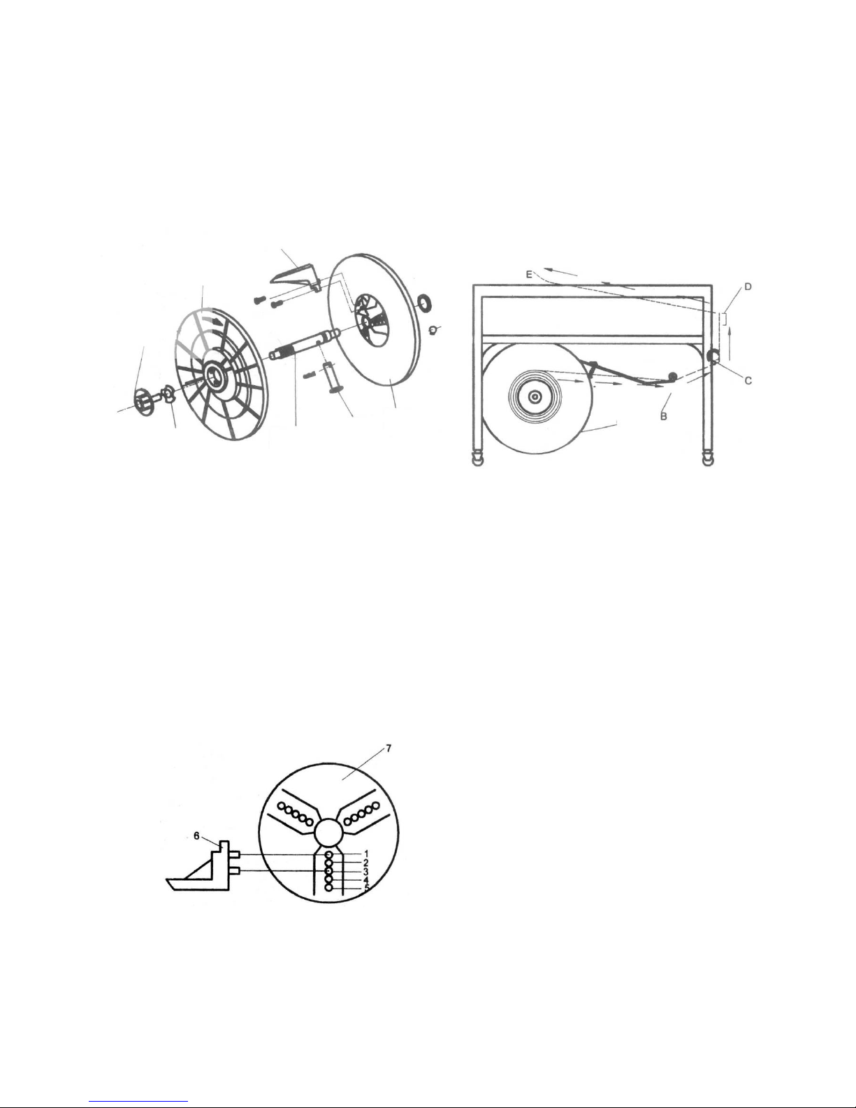
Refer to Figure 7. and proceed as follow:
1. Withdraw the dispenser assembly. Place the assembly as
shown.(Fig.7,P.6)
2. Turn the reel nut hand wheel to disengage from the roll pin
that protrudes from the shaft.
3. Lift the plastic flange B from the dispenser shaft.
4. Place a coil of strap on the plastic flange A allowing the
shaft to poke through the plastic wrap. Pay-off must be from
the top of the coil if the friction brake is to operate properly,
as shown in Figure11.
-5-
Page 10
5. Replace the Plastic B and reinstall the Reel nut hand
wheel.
6. At this time the securing straps can be removed from the
coil of strap.
7. Place the dispenser assembly back into the rearend of
the machine, Make sure the assembly is placed in
properly. The Reel nut hand wheel should be positioned
to the right. This can be verified by noting that the drag
arm of the friction brake contacts the Plastic flange A.
8. When installed, close the rear panel door.
1. Open the right-hand door and pull about 3 feet (1M)of
strap from the coil.
2. Thread the strap through the looper (B), pass it under
roller (C) and allow it to exit the cabinet. Close the
right-hand door.
3. Pull up on the strap, then insert the lead-end between
the guide and roller (D).
4. Continue to push the strap through the head until it
can be seen at point (E).
FLANGE
PLASTIC
REEL CENTER
CLAW
REEL UNT
HANDWHEEL
Y-TYPE
WASHER
FIGURE 7. DISPENSER ASSEMBLY
DISPENSER
SHAFT
PLASTIC
FLANGEA
PIN
FIGURE 9. STRAP THREADING DIAGRAM
STRAPPING CYCLE
The machine is now ready for strapping a
package.
To operate the EXS-206, proceed as follow:
1. Push the power switch to the “NO” position and
allow the hot knife 5 seconds to reach operating
temperature.
2. Place a package on the table top, directly above
the sealing head. Allow the package to contact
the two package stops.
3. Grasp the strap on the left side on the package,
bring it over the package and insert the lead-end
into the strap closes LS1, the strap will be
tensioned, welded and then released, all
automatically. “CAUTION!!” Be sure to keep
fingers from beneath the strap.
Please follow instruction below to adjust the Reel center
claw (part NO. #4-07000-130) for various inner coils.
Refer to Fig. 8:
1. For 200mm inner coil diameter, position 2 holes on
the Reel center claw ( Item 6 ) to #1 and #3 holes of
the Plastic Flange A (Item 7).
2. For 230mm inner coil diameter, position 2 holes on
the Reel center claw ( Item 6 ) to #2 and #4 holes of
the Plastic Flange A (Item 7).
3. For 280mm inner coil diameter, position 2 holes on
the Reel center claw ( Item 6 ) to #3 and #5 holes of
the Plastic Flange A (Item 7).
FIGURE 8. THREADING STRAP THROUGH MACHINE
4. Remove the strapped package and note the
length of the strap fed out for the next cycle.
Adjust the time as needed.
5. Note the con dition of the weld and t he tension of
the tie on the package, If the condition of the weld
or the level of tension is unsatisfactory, adjust the
hot knife temperature or the tension level as
needed. Ref: Operating Adjustments.
The threading procedure involves routing strap from the
dispenser and up through the strapping head.
Refer to Figure 9 and proceed as follows:
-6-
Page 11
OPERA TING ADJUSTMENTS
ADJUSTING TENSION
If tension adjustment is required, proceed as follows:
1. Loosen the locking knob at the right hand end of the
machine.
2. Turn the knurled knob, located at the rear of the machine,
clockwise to increase tension, counterclockwise to
decrease tension.
3. When set to the desired tension level, tighten the locking
knob.
ADJUSTING HOT-KNIFE TEMPERATURE
FIGURE 10. EXIT GUIDE
If the weld appears to be only minimal, it may be that the
temperature is improperly set. Make all corrections, in
small increments, according to the following condition.
RASING HOT-KNIFE TEMPERATURE
If the weld appears to have insufficient heating, turn the
hot-knife rheostat (item 19 on the PC board), in a
clockwise direction.
LOWERING HOT-KNIFE TEMPERATURE
FIGURE 11. ENTRY GUIDE
If the condition of the weld appears to have been over
heated, turn the rheostat counter clockwise.
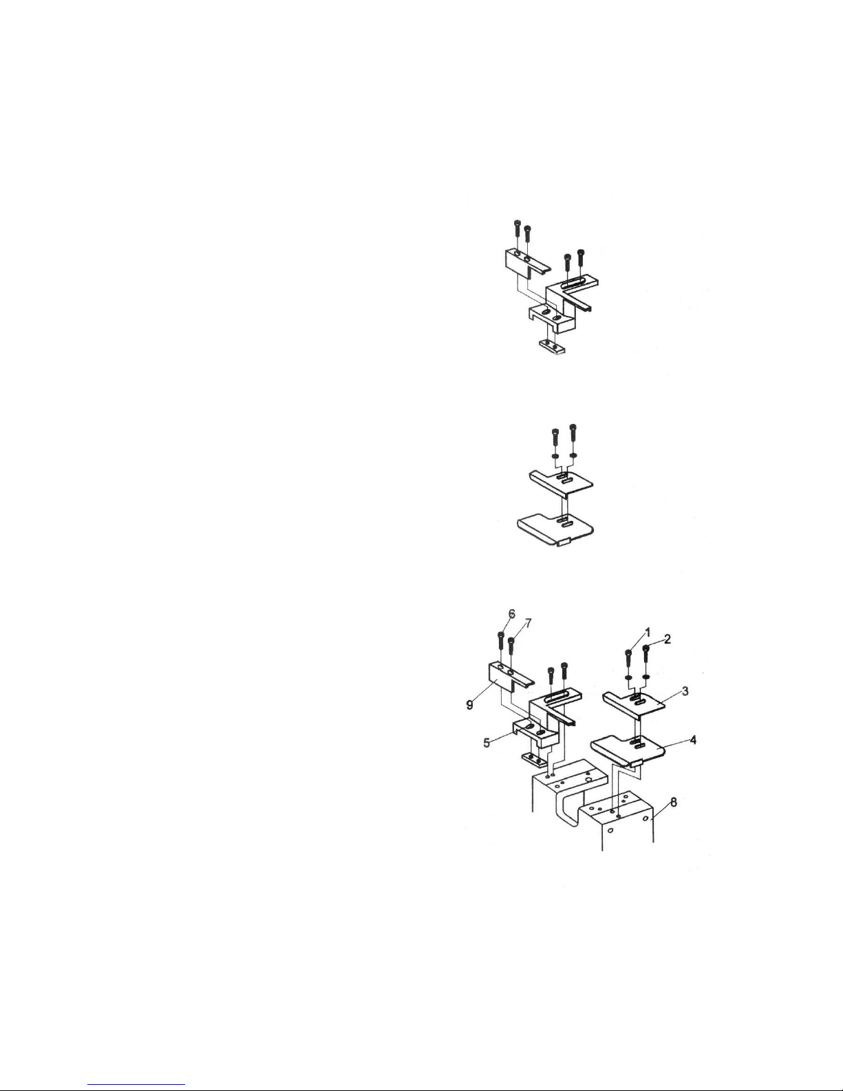
STRAP GUIDE ADJUSTMENT TO VARIOUS
WIDTH OF P.P. STRAP
1. Strap Guide Adjustment
Loosen the Socket head cap screws (item #1 #2) and put
the upper Strap Guide against the side of Main body
block (item #8). Place p.p. strap between upper Strap
Guide (item #3 ) and lower Strap Guide (item #4) properly .
Screw those 2 Socket head cap (item #1& #2) screws
real tight.
2. Strap Guide Adjustment
Loosen the Socket head cap screws (item #1 & #2).
Place p.p. strap between strap Guide (item #5) and
Adjusting strap (item #9). Adjust item #9 to a proper room
for the p.p. strap then tighten the Socket head cap screws
(item #6 & #7).
FIGURE 12. GUIDE LOCATION
-7-
Page 12
PRINCIPLES OF OPERATION
GENERL
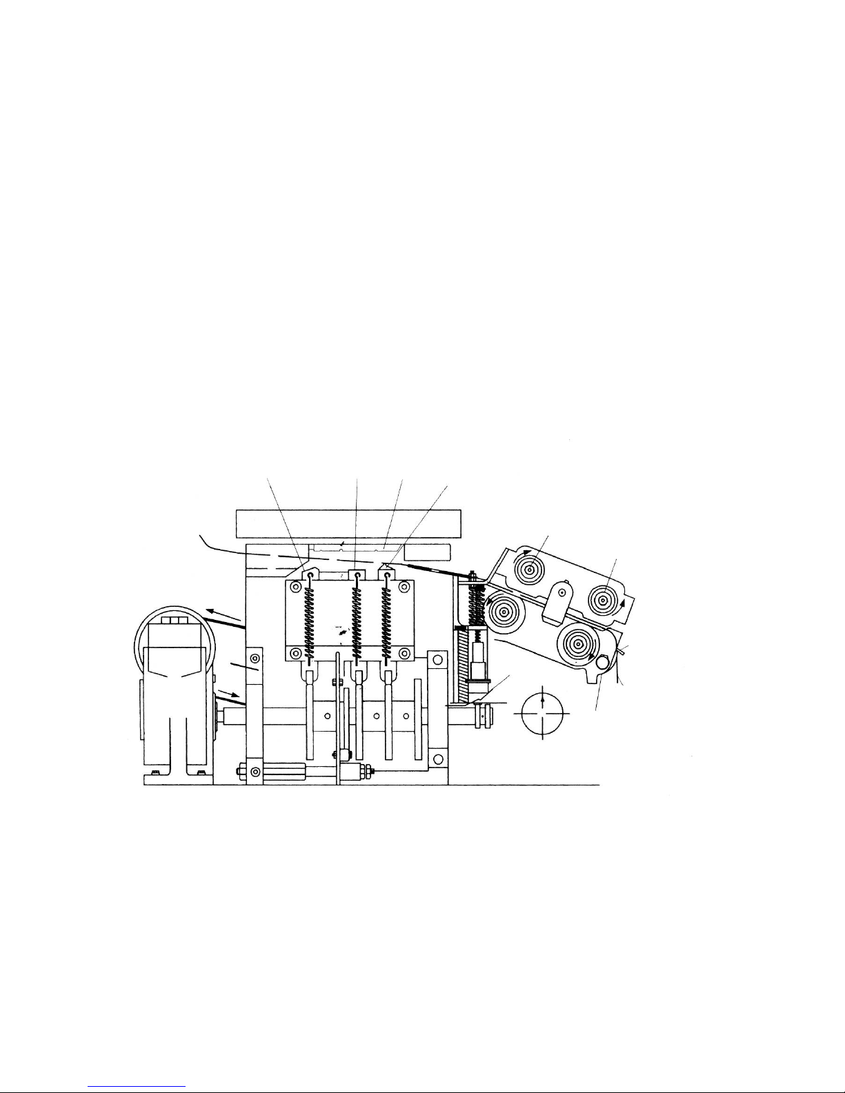
1. NEUTRAL POSITION. When the strap is
initially threaded through the machine. It
enters the head under the strap guide and
over roller D. between two sets of feed and
tension rollers and on through a slot in the
end gripper. It then passes beneath the
anvil. Over the welding clamp and holding
gripper and out into the strap channel on the
left-hand access to it,
The strapping cycle can be divided into three
distinct operations:
a. Grip and tension.
b. Weld, cut, and release.
c. Feed.
The following descriptions refer to Figures 13
through 18. Note that both the mechanical
and the control function of the micro switches
are described.
HOLDING
GRIPPER
WELDING
CLAMP
END
GRIPPER
ANVIL
FEED
ROLLERS
TENSION
ROLLERS
PACKAGE
STRAP
GUIDE
HOME
ROLLERD
SHAFT
ROTATION
STRAP
AT REST
FIGURE 13. NEUTRAL POSITION
-8-
Page 13
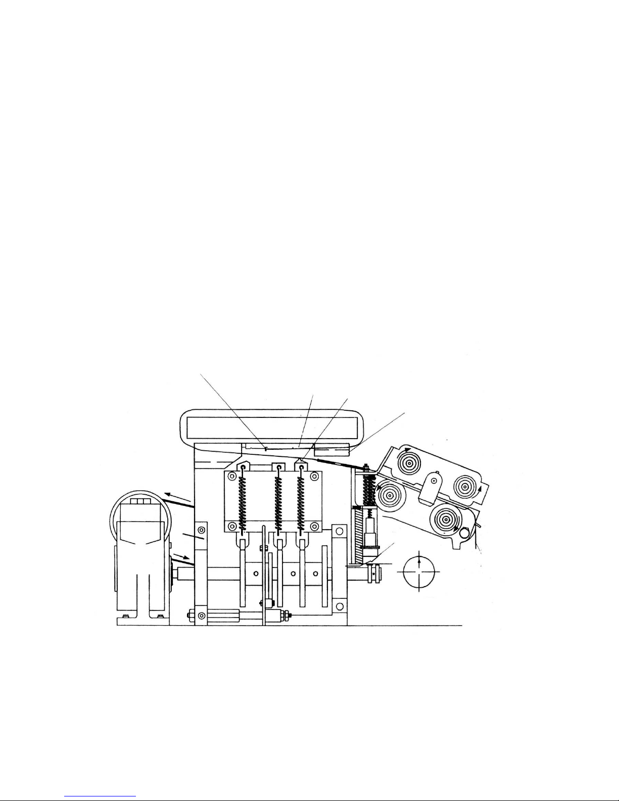
2. ENCIRCLING PACKAGE; TRIPPING LS1.
Grip and tension is initiated by the operator
who encircles the package with the strap and
inserts the strap end into the slot of the upper
strap guide on the right-hand end of the
machine. In doing so, the strap is guided
between the gripper portion of the end gripper
and anvil then into a slot in the anvil where it
makes contact with the start switch detector
lever. As the lever moves to the left, it trips the
cycle start switch, LS1.
START SWITCH (LS1)
DETECTION LEVER
END
GRIPPER
ANVIL
UPPER
STRAP
GUIDE
PACKAGE
HOME
STRAP
AT REST
SHAFT
ROTATION
FIGURE 14. ENCIRCLING PACKAGE; TRIPPING LS1
-9-
Page 14
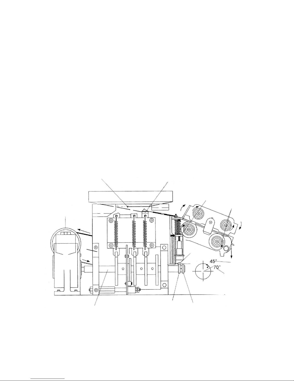
3. TENSION. When LS1 is closed,
the electromagnetic clutch energizes and
the cam shaft rotates approximately 45
degrees. This small amount of shaft
rotation is controlled by LS3, mounted at
the right-hand end of the cam shaft.
When LS3 closes it de-energizes the
electromagnetic clutch and the end
gripper will have been moved upward to
contain the upper strap beneath the
anvil.
The tension lever pivots and closes
the tension rollers. The tension rollers
close against the strap, drawing it back
through the head, thus tensioning it
around the package. When full tension
detector reacts at same time, the
electromagnetic clutch energizes again.
LS1 DETECTION
LEVER
END
GRIPPER
TENSION
ROLLERS
TENSION
LEVER PACKAGE
ELECTROMAGNETIC
CLUTCH
END
GRIPPER
CLOSED
HOME
SHAFT
ROTATION
CAM SURFACE
LS3
CAM SURFACE
LS5
CAM SHAFT
FIGURE 15. TENSION
-10-
Page 15

4. HOLDING GRIPPER RISES; HOT-KNIFE
MOVES INWARD. Momentarily electron
tension detector energizes the control circuit to
energize the electromagnetic clutch and turn
the cam shaft. As the cam shaft turns, the
holding gripper rises to contain the other end
of the strap beneath the anvil. The tension
lever is lowered to release tension and the
welding clamp begins to rise.
It’s important to note that all tension to the
strap must be released before the strap is cut,
otherwise the strap-end could be damaged
and feeding reliability will be affected. The
hot-knife moves in between the two layers of
strap.
NOTE: TENSION ROLLERS
ARE RELEASED AND STRAP
IS A T REST.
ANVIL
HOLDING
GRIPPER
HOT
KNIFE
TENSION
LEVER
WELDING
CLAMP
TENSION
ROLLERS
PACKAGE
ELECTROMAGNETIC
CLUTCH
HOME
120°
HOLDING
GRIPPER
SHAFT
ROTATION
FIGURE 16. HOLDING GRIPPER AND HOT-KNIFE
-11-
Page 16
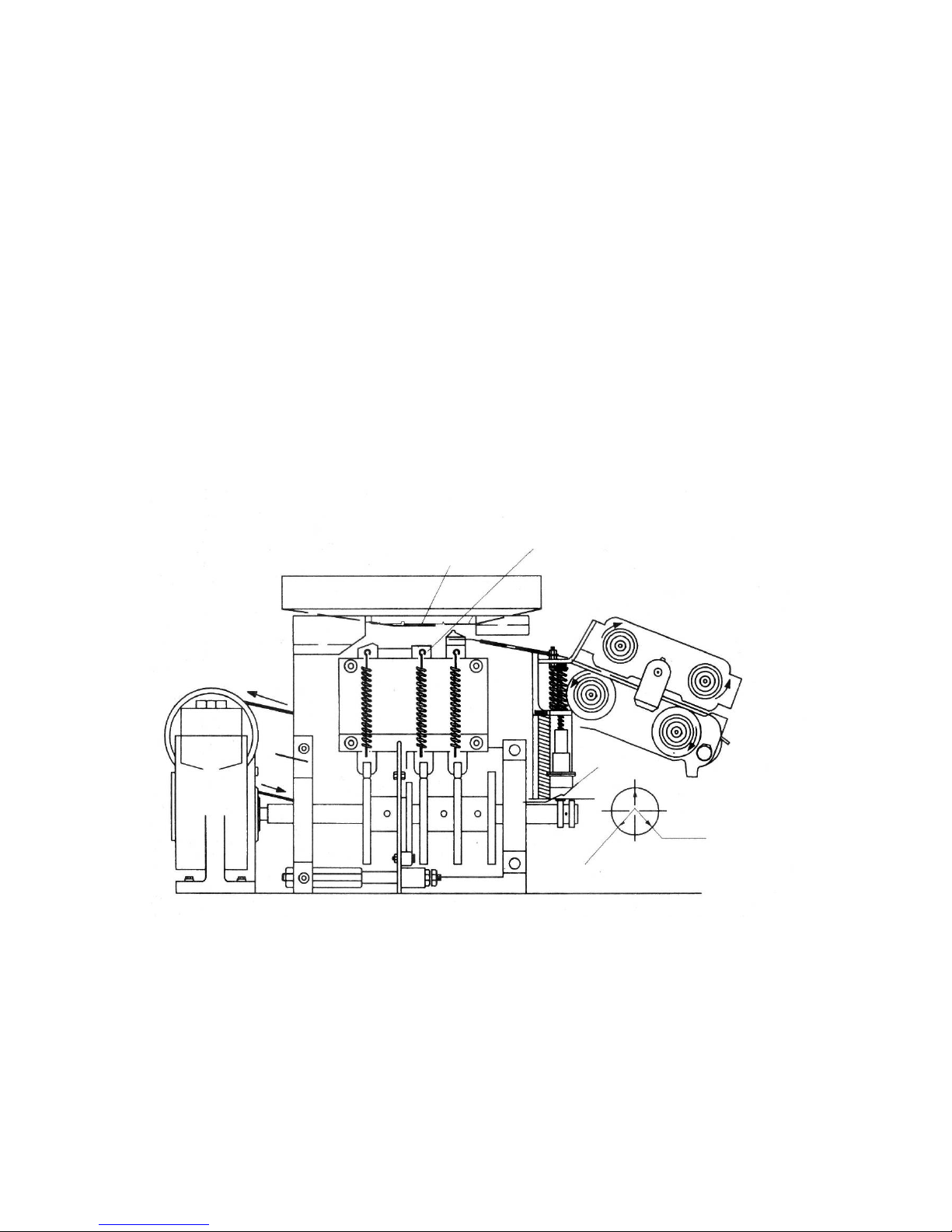
5. STRAP IS CUT; WELD IS MADE. The
welding clamp cuts the strap during it’s
upward movement then pushes the
upper surface of the lower strap
against the lower surface of the
hot-knife. It then pushes the hot-knife
the lower surface of the upper strap.
PACKAGE
WELDING
CLAMP
HOT KNIFE
HOME
135°
STRAP CUT
SHAFT
ROTATION
210°
WELD
PUSE
FIGURE 17. STRAP IS CUT & WELD IS MADE
-12-
Page 17
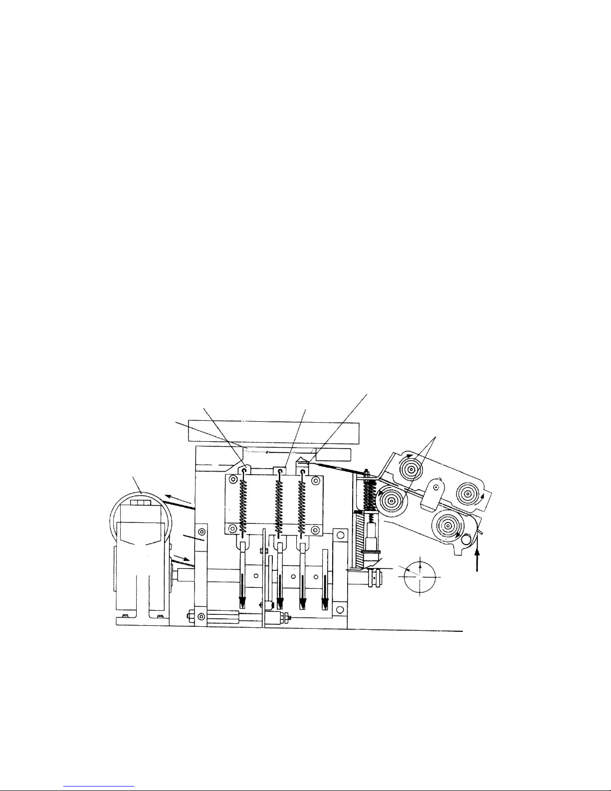
6. WELD IS RELEASED; HEAD RETURNS
TO HOME POSITION.
The hot-knife retracts and the welding clamp
pushes the two molten surfaces together,
welding the strap.
After this short delay to ensure that the strap
fuses properly , the cam shaf t again turns and
the holding gripper retract to the neutral
position.
The anvil then retracts and welded strap is
released to the lower side of the package.
The cam shaft returns to the home
position and closes LS3 and LS5.
The electromagnetic clutch is
de-energized by LS3 while LS5
energizes SOL1. As the solenoid
pulls down on the tensioning lever,
the feed rollers close against the
strap, pushing it through the head
and out into the strap channel. The
feed timer de-energizes and sol1 is
released.
Strap feed stops and the machine is
ready for the next cycle.
NOTE: SOL1 ENERGIZES TO CLOSE
FEED ROLLERS AND FEED STRAP
AFTER THE CAM SHAFT REACHES
HOME POSITION.
HOLDING GRIPPER
END GRIPPER
WELDING GRIPPER
FEEDING ROLLER
ANVIL
-13-
GEAR REDUCER
SHAFT ROTATION
FIGURE 18. WELDING STRAP IS RELEASED;
HEAD IS IN HOME POSITION; STRAP FEEDS
Page 18
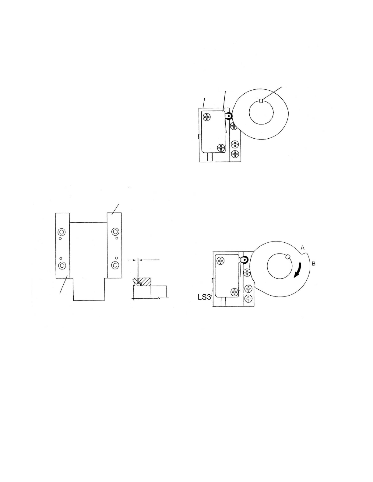
ADJUSTMENTS CLEARANCES
Anvil to ensure that anvil operates
smoothly a minimum clearance between
the anvil and the left and right guides
must be maintained. To adjust, proceed
as follows:
VERTICAL
LOCATION OF
KEY ESTABLISHES
HEAD IN HOME
POSITION
1. Make sure the right-hand guide is
securely mounted.
2. Loosen the left-hand guide mounting
screws.
3. Insert a shim, .002” (0.50mm) thick
0..118” (3mm) wide by 5” (130mm)
long between the shoulder of the
anvil and the left guide.
4. Push the left guide against the anvil
and tighten the left guide mounting
screws.
5. Remove the shim and check to make
sure the anvil moves smoothly.
LS5
SWITCH
CLOSED
FIGURE 20. LS5
3. Position LS3 as shown in Figure 24.
When set, tighten the mounting
screws.
As the cam rotating clockwise, the
touching point of micro switch with
cam changes from B to A, then the
cooling time starts.
SWITCH CAM: The outer cam actuates
RIGHT-HAND
GUIDE
WHEN SET
CLEARANCE
.001”(0.02mm)
ON EACH SIDE
LS3. To make sure the cams are set
properly, proceed as follows:
1. Make sure the machine is in the
neutral or home position.
2. If the micro-switches need adjusting,
loosen the mounting screws and LS5
as seen in Figure 20. When properly
set, tighten the mounting screws.
WELDING CLAMP AND END GRIPPER.
To adjust the clearance between the
welding clapper and the gripper, refer to
Figure 22 and proceed as follows:
1. Remove the anvil.
2. Loosen the two socket head cap
screws that secure the “L” shaped
adjustment bracket to the casting.
ANVIL
INSERT
SHIM A T
THIS SIDE
FIGURE 19. ANVIL CLEARANCE
FIGURE 21.LS3
3. Push the block left or right to adjust the
clearance secure the “L” shaped
adjustment bracket to the casting.
4. When set, securely tighten the
mounting screw.
-14-
Page 19
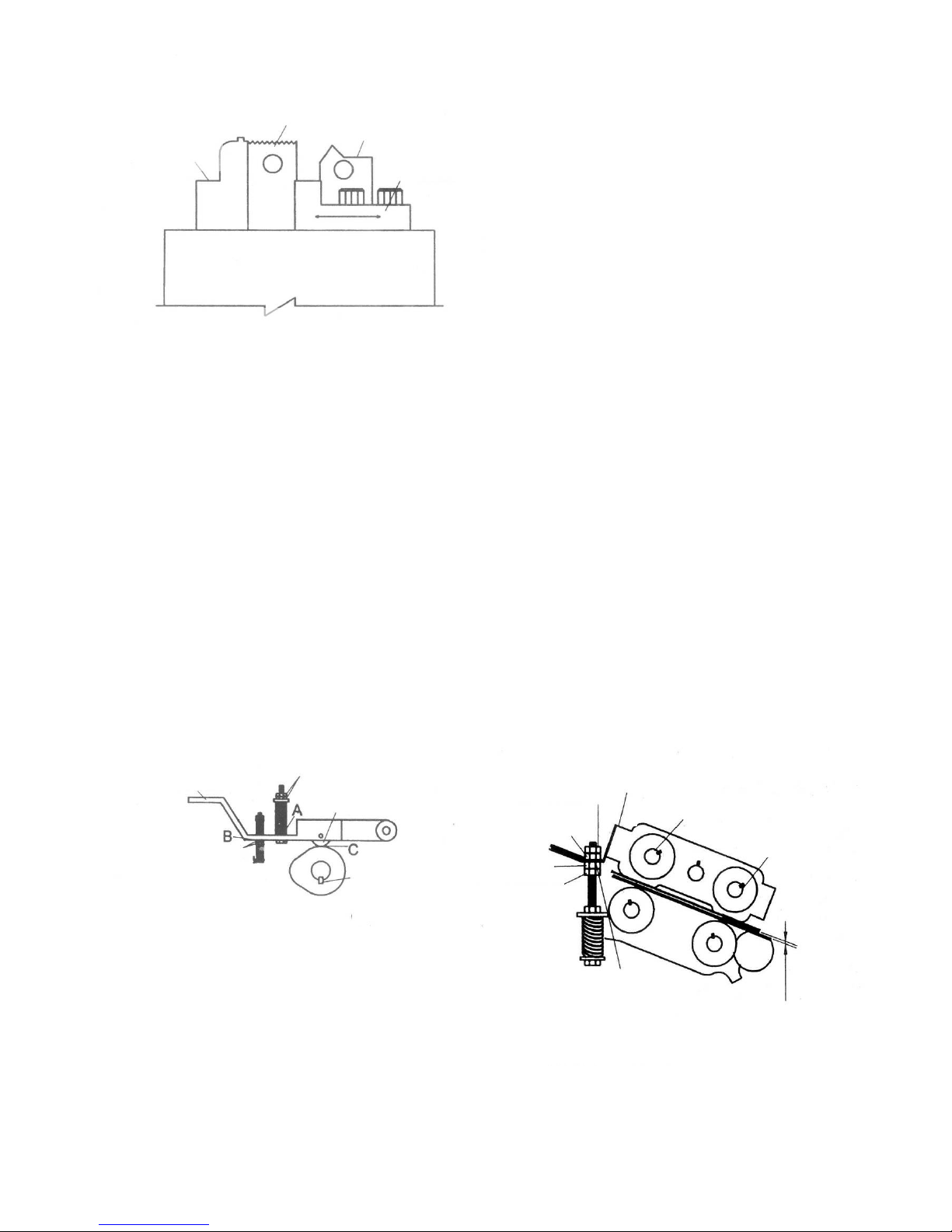
4. If there is clearance at any point,
loosen locknuts (1) and (2) and adjust all
clearance out at points A, B and C.
5. When set, tighten the locknuts.
WELDING
CLAMP
ADJUSTMENT
BRACKET
HOLDING
GRIPPER
END
GRIPPER
FEED AND TENSION ROLLERS. When
the machine is in the neutral position.
The feed and tension rollers should not
come into contact with the strap. The
clearance between the rollers should
be .040” (1.0mm). To adjust the feed
rollers away from the strap proceed as
follows:
PAETS SEEN FROM REAR SIDE HEAD
FIGURE 22. WELDING CLAMP AND GRIPPER
CLEARANCE
1. Loosen the locknuts and turn all 4
nuts upward. Make all adjustments in
very small increments. When set.
Insert a 0.202” (0.5mm) shim
between the angle plate and locknut
B and tighten locknut A against
locknut B
Note: If the cutting surface of the welding
clamp has become dull, the welding
clamp can be turned 180 degrees, thus
doubling the life of the part.
TENSION LEVER. Before making any
adjustments to the tension lever, check
to see if the tension lever is in a lever
condition. To check and adjust if need be
proceed as follows:
2. Remove the shim and press down on
the angle plate. Tighten the locknuts
C and D.
1. Manually turn the rotor of the
electromagnetic clutch until the key,
seen at the end of the end of the cam
shaft is positioned as shown in Figure
23.
To adjust the tension rollers away from
the strap reverse the above procedure.
2. Make sure the tension lever bearing is
in contact with the surface of the cam.
3. If there is no clearance at point A, B
and C then the tension lever is
considered lever..
-15-
TENSION
LEVER
LOCKNUTS 1
BEARING
LOCKNUT B
LOCKNUT C
LOCKNUT D
ANGLE
PLATE
LOCKNUT A
NOTE
POSITION
OF KEY
FEED ROLLER
TENSION
RPLLER
LOCKNUTS 2
FIGURE 23. ADJUSTING TENSION LEVER
CLEARANCE BETWEEN
ROLLERS SHOULD BE
.040” (1.0mm)
FIGURE 24. ADJUSTING FEED AND TENSION
ROLLERS
INSERT .020”
(0.5mm)SHIM
A T THIS POINT
Page 20
-16-
MAINTENANCE
GENERAL. Periodic checks of all drive belts for
replacement should be made to prevent worn cut or
stretched belts which will affect tension.
LUBRICATION. Make sure the machine is clean
before applying lubricants to the points shown in the
figure below. Note: Use a brush or compressed air
to dispose of debris.
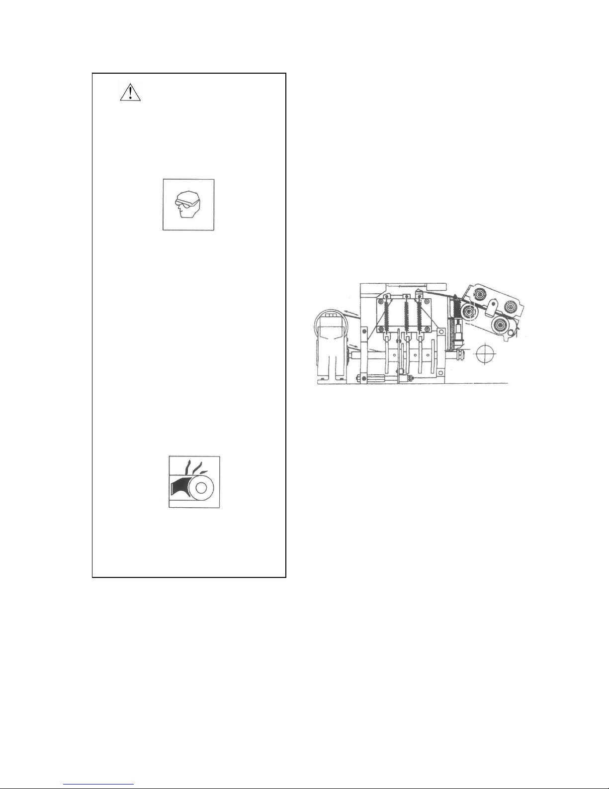
TENSION TRIP ARM ASSEMBLY SLEEVES.
Apply a few drops of light machine oil to the edge of
the sleeve so that the oil can penetrate to the
shoulder of the screw.
TOP SLIDE, GUIDE PLATES, WELDING CLAMP,
END GRIPPER, AND HOLDING GRIPPER.
Apply light machine oil to these parts at the point
indicated in Figure 25.
REAR REDUCE. Replace the oil in the gear
reducer once a year in the following manner:
1. Remove the lower plug and allow the oil to drain
from the gearing.
2. Reinstall the lower plug and fill with gear oil.
3. Reinstall the upper plug
FIGURE 25. LUBRICTION POINTS
WARNING
BEFORE SERVICING MACHINE
Wear safety glasses with
side shields which conform
to ANS Standard Z87.1
Failure to wear safety
glasses could result in
severe personal injury
or blindness.
PROTECT YOUR EYES
READ GENERAL SAFETY
INSTRUCTION, PAGE 2 OF
THIS MANUAL
● only trained personnel should
service machine.
● Unless specified, shut off and
disconnect all electrical power.
● Follow all service instructions.
● Make sure the hot-knife blade
is cool before servicing.
● Use the correct tools.
● Never adjust, repair or oil
moving machinery.
Note: The following parts should NEVER be
lubricated:
1. Electromagnetic clutch
2. Roller assemblies
3. Belts and pulleys
4. Clutch disc
Note: When you move the machine, you
should push it slowly.
Page 21

TROUBLESHOOTING
SYMPTOM: Strap jams in strapping
head while feeding.
CAUSE
1. Debris accumulation in feed/tension
roller area.
SYMPTOM: Strap pulls from head
before seal and cut-off.
1. Worn gripper.
SYMPTOM: Strap is not feed.
1. Solenoid 1 will not activate.
SYMPTOM: Strap is not being cut-off
upon completion of strapping cycle.
1. LS3 inoperative
2. LS3 improperly adjusted.
3. Clearance between welding clamp
and end gripper too great.
4. Cutting surface on welding clamp is
dull.
SYMPTOM: Machine will not complete
seal and cut-off.
1. The belt that activates the tension
trip arm is broken or has come off
the pulleys.
2. LS2 inoperative.
SYMPTOM: Poor strap weld.
1. Hot-knife temperature is too high or
too low.
2. The 5 amp fuse has blown.
REMEDY
1. Disassemble the roller assembly and
remove debris. See Adjustment Section.
Figure 24.
1. Replace gripper
1. Adjust the clearance of LS5 in relation to
the switch cam. Refer to Figure 20.
2. Replace LS5.
3. Adjust LS3 if needed to ensure the head
stops in HOME position.
1. Replace and adjust LS3. refer to Fig. 21.
2. Adjust LS3 as required.
3. Adjust the clearance as detailed in
adjustments and clearance section.
4. Turn the welding clamp 180° to bring new
cutting surface into play. Details in
Adjustments and Clearance Section.
1. Replace the belt, if necessary. Remount
the belt if it has come off the pulleys.
Refer to Parts List Figure 4.
2. Replace LS2. Refer to Parts List, Fig. 4
1. Adjust the hot-knife temperature. Details
in Operating Instructions Section.
2. Before replacing the 5 amp fuse,
attempt to identify the cause of why the
fuse failed and make necessary repairs.
-17-
Page 22

Page 23

TABLE OF CONTENTS
TABLE OF CONTENS ---------------------------------------------------------------------------------- 1
FIG.1 WELDING COMPONENT ----------------------------------------------------------------- 2~3
FIG.2-1 DRIVE AND CAM ASSEMBLY --------------------------------------------------------- 4~5
FIG.3 STRAP FEED/TENDION ASSEMBLY ------------------------------------------------- 6~7
FIG.4-4 TENSION ADJUSTMENT AND SENSING ASSEMBLY-------------------------- 8~9
FIG.5 HOT--KNIF AND TENSION LEVER ASSEMBLY---------------------------------- 10~11
FIG.6-3C CABINET COMPONENTS----------------------------------------------------------------- 12~13
FIG.8-2 DISPENSER ASSEMBLY----------------------------------------------------------------- 14~15
FIG.9-8 ELECTRICAL COMPONENTS----------------------------------------------------------- 16~17
FIG.10-3 CONTROL BOX ASSEMBLY------------------------------------------------------------ 18~19
ELECTRICAL SCHENATIC------------------------------------------------------------------------------- 20
Page 24

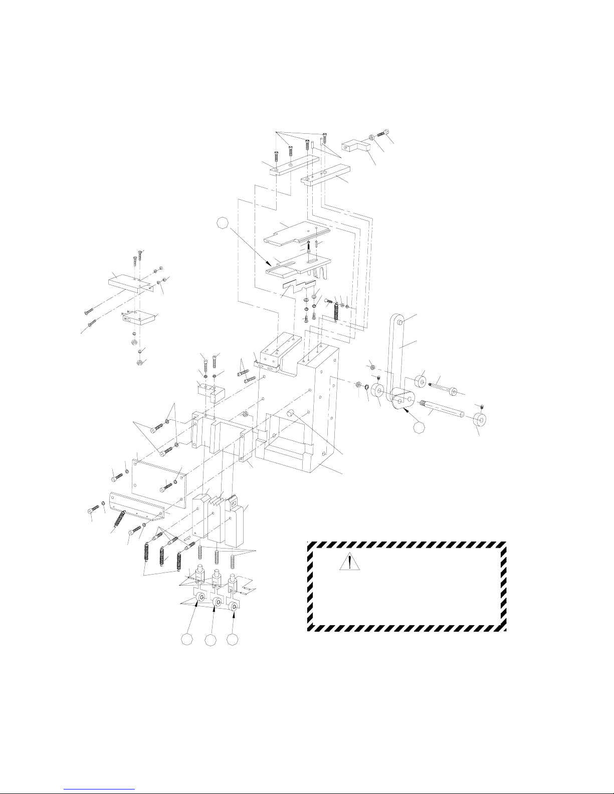
PARTS LIST, FIGURE 1 WELDING COMPONENTS
KEY Q'TY PART NO. DESCRIPTION
FPS-500-010
1 1 4-01010 END GRIPPER UNI
T
2 1 4-01020 WELDING CLAMP UNIT
3 1 4-01030 HOLDING GRIPPER UNI
T
4 1 4-01041 SEPARATING PLATE UNI
T
5 1 4-01050 SEPARATING ARM UNI
T
11 1 4-01000-110 Main body block
12 1 4-01000-120 Guide plate, right hand side
13 1 4-01000-130 Guide plate, left hand side
14 1 4-01000-140 Top cover holder
15 1 4-01000-150 Retainer, top cover holder
16 1 4-01000-162 Microswitch seat
17 1 4-01000-170 Microswitch spring plate
18 1 4-01000-180 Spring hook
19 2 4-01000-190 Screw
20 1 4-01000-200 Guide slot
21 1 4-01000-210 Guide plate
22 1 4-01000-220 L-type angle plate
23 1 4-01000-230 Spring hook plate
24 1 4-01010-240 End gripper
25 3 4-01010-250 Clevis
26 3 4-01010-260 Spring hook
27 1 4-01020-270 Welding clamp
28 1 4-01030-280 Holding gripper
29 1 4-01040-290 Separating plate
30 1 4-01040-301 Microswitch detector lever(out)
32 1 4-01050-320 Separating arm
33 2 4-01050-330 Sleeve, separating arm pin
34 1 4-01050-340 Separating arm pin
101 7 200A05012 Socket head cap screw, M5*12
102 1 200A05006 Socket head cap screw, M5*6
103 1 200A05016 Socket head cap screw, M5*16
104 1 200A05020 Socket head cap screw, M5*20
105 1 200A05025 Socket head cap screw, M5*25
106 2 200A06025 Socket head cap screw, M6*25
107 2 200A06050 Socket head cap screw, M6*50
108 2 200G05008 Socket head set screw, M5*8
109 1 200E04016 Phillips head machine screw, M4*16
111 3 200E03015 Phillips head machine screw, M3*15
112 2 201A03 Hex nut, M3
113 1 201A04 Hex nut, M4
114 1 201A05 Hex nut, M5
115 2 201A08 Hex nut, M8
116 2 202B03 Lock washer, M3
117 4 202B04 Lock washer, M4
118 7 202B05 Lock washer, M5
119 1 202B08 Lock washer, M8
120 5 202B06 Lock washer, M6
123 1 200A04016 Socket head cap screw, M4*16
124 2 200E04008 Phillips head machine screw, M4*8
125 2 202A0410 Plain washer, M4*10
126 3 2212310042 Compression spring, 2.3*10*42
127 1 2201210020 Tension spring, short 1.2*10*20
128 4 2201011022 Tension spring, long 1*10.8*22
129 1 104G010 Microswitch, heavy MQS-216 16A
130 4 210A0635ZZ Ball bearing, 635ZZ
131 1 211A0414 Spring pin, 4 dia.*14
132 1 211A0520 Spring pin, 5*20
133 3 211A0514 Spring pin, 5 dia.*14
134 5 211A0318 Spring pin, 3 dia.*18
135 2 200E03005 Phillips head machine screw, M3*5
136 2 202A0308 Plain washer, M3*8
2
Page 25
107
24
20
18
11
115
120
22
115
WARNING
33
33
5
34
119
108
4
30
19
118
118
103
104
16
129
125
111
117
116
112
124
136
135
17
109
113
117
116
128
102
118
29
131
14
13
134
12
101
32
114
130
132
117
15
123
105
108
FIGURE1.WELDING COMPONENTS
do this can affect a tool's operation
and present a safety hazard.
and replaced if worn or broken.Failure to
All parts must be periodically inspected
118
107
103
128
133
3 1
2
130
127
133
25
128
26
120
134
126
106
118
103
23
28
27
120
21
3
Page 26

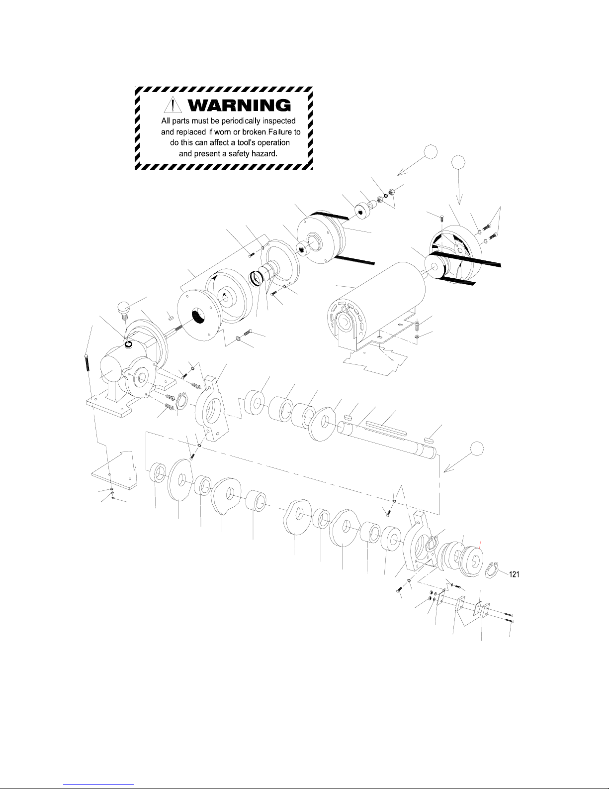
PARTS LIST, FIGURE 2 DRIVE AND CAM ASSEMBLIES
KEY Q'TY PART NO. DESCRIPTION
FPS-500-021
1 1 4-02010 REDUCTION GEAR UNI
T
2 1 4-02021 CAM UNI
T
3 1 4-02030 MOTOR FAN UNIT,FOR 50H
Z
3 1 4-02031 MOTOR FAN UNIT,FOR 60H
Z
11 1 4-02010-110 Pulley
12 1 4-02010-120 Reduction gear
14 1 4-02020-140 Cam shaft, M17*192
15 1 4-02020-150 Cam
16 1 4-02020-160 Cam
17 1 4-02020-170 Cam
18 1 4-02020-180 Cam
19 1 4-02020-190 Cam
20 1 4-02020-210 Cam
20.1 1 4-02021-200 Cam
21 1 4-02020-211 Bearing bracket (aluminium)
22 1 4-02020-221 Bearing bracket (aluminium)
23 1 4-02000-230 Motor pulley, for 50Hz
23 1 4-02000-231 Motor pulley, for 60Hz
24 1 4-02000-240 Motor fan
25 1 4-02000-250 Microswitch seat
27 1 4-02000-270 Plate
28 1 4-02000-280 Clutch shrim
101 10 200E04008 Phillips head machine screw, M4*8
102 10 202B04 Lock washer, M4
103 2 201A10 Hex nut, M10
104 1 202B10 Lock washer, M10
105 2 201A03 Hex nut, M3
106 8 200M06025 Hex bolt with washer, M6*25
107 8 202A0613 Plain washer, Ф6*13
108 12 202B06 Lock washer, M6
109 8 201A06 Hex nut, M6
110 4 200C06020 Hex bolt, M6*20
112 1 200G06010 Socket head set screw, M6*10
113 2 200A05012 Socket head cap screw, M5*12
114 3 200A06020 Socket head cap screw, M6*20
115 1 200A06045 Socket head cap screw, M6*45
116 2 200E03030 Phillips head machine screw, M3*30
118 2 202B05 Lock washer, M5
119 2 202B03 Lock washer, M3
120 4 202A061620 Plain washer, M6*16*2
121 2 212AS17 Ring, S-17
122 2 210A6201ZZ Ball bearing, 6201ZZ
123 1 101A1160018 Motor, 1PH, 110/220V60Hz,1/4HP
123 1 101A2350018 Motor, 1PH, 220/230V50Hz 1/4HP
123 1 101A2450018 Motor, 1PH 240V50Hz 1/4HP
124 2 210A6003ZZ Ball bearing, 6003ZZ
125 1 202G121604 Spacer, M12*16*4
126 1 202E121801 Shim, M12*18*1
126 1 202E121802 Shim, M12*18*0.2
126 1 202E121804 Shim, M12*18*0.4
127 2 213A0505014 Key, 5*5*14
128 1 213A0505080 Key, 5*5*80
129 2 213A0505016 Key, 5*5*16
130 2 202F172906 Plastic circlet, M17*29*6
131 2 202F172910 Plastic circlet, M17*29*10
132 2 202F172912 Plastic circlet, M17*29*12
133 1 202G121608 Spacer, M12*16*8
135 1 226K163 Oil cover
136 1 227A02020 Rubber washer, (Ф20)
137 1 102F06 Magnetic clutch CD-F-0.6
138 2 104G012 Microswitch with roller, heavy (LS-3,5) MQS-2, 16A 250VAC
140 1 202F172908 Plastic circlet, M17*29*8
4
Page 27
106
107
133
23
125
122
11
122
104
103
24
112
118
113
15
131
19
LS-5
108
105
114
124
140
22
119
25
138
102
101
116
LS-3
27
21
101
108
107
109
131
130
18
16
121
108
115
136
106
108
114
12
135
137
127
131
102
20
114
108
20.1
14
128
129
126
101
124
102
101
132
17
123
102
FIGURE 2. DRIVE AND CAM ASSEMBLIES
2
1
3
28
127
132
139
121
5
Page 28

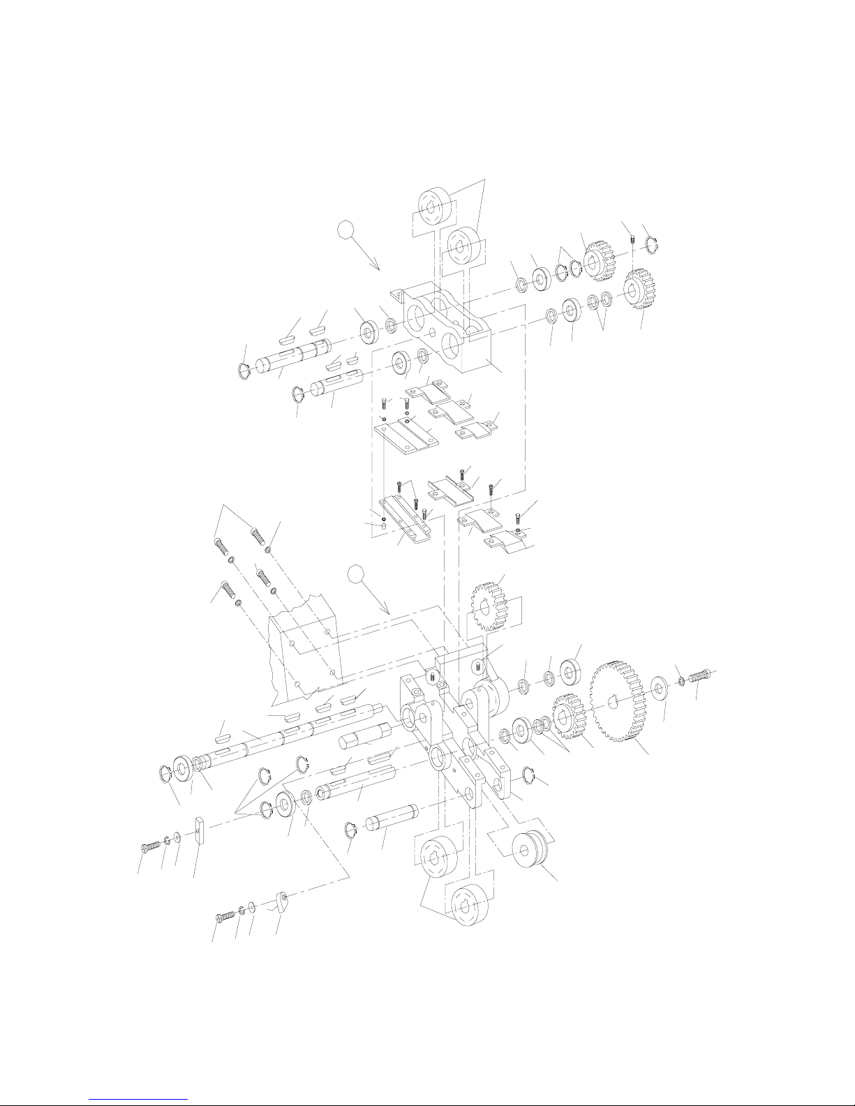
PARTS LIST, FIGURE 3 STRAP FEED/TENSION ASSEMBLY
KEY Q'TY PART NO. DESCRIPTION
FPS-500-030
1 1 4-03011 BEARING HOUSING, UPPER UNIT (ALUMINIUM)
2 1 4-03021 BEARING HOUSING, LOWER UNIT (ALUMINIUM)
11 1 4-03010-110 Roller shaft 15*85
12 1 4-03010-120 Roller shaft 15*66
13 1 4-03011-130 Bearing housing, upper (aluminium)
14.1 2 4-03010-140 Steel roller
14.2 2 4-03010-142 Steel roller
15 2 4-03010-150 Nylon gear, 20 teeth
16 1 4-03010-160 Gear
17 2 4-03010-170 Strap guide
18 1 4-03010-180 Strap guide
20 1 4-03020-200 Pin
21 1 4-03020-210 Roller shaft 10*49
22 1 4-03020-220 Roller shaft 15*85
23 1 4-03020-231 Tightness adjustment shaft 15*285
24 1 4-03021-240 Bearing housing, lower (aluminium)
25 1 4-03020-250 Nylon gear, 40 teeth
27 1 4-03020-270 Plastic gear
28 1 4-03020-280 Plastic roller
29 1 4-03020-290 Strap guide
30 1 4-03020-300 Strap guide
31 1 4-03020-310 Strap guide
32 1 4-03020-320 Strap guide
33 1 4-03020-330 Strap guide
100 1 200E03016 Phillips head machine screw, M3*16
101 6 200E04008 Phillips head machine screw, M4*8
103 12 200F04008 Flat head cap screw, M4*8
105 1 200A05012 Socket head cap screw, M5*12
106 2 200G05008 Socket head set screw, M5*8
108 4 202B06 Lock washer, M6
109 4 200A06020 Socket head cap screw, M6*20
110 1 104Y002 Inductor SK3-X
111 7 202B04 Lock washer, M4
112 7 202A0410 Plain washer, M4*10
114 1 202B05 Lock washer, M5
116 1 202A062120 Plain washer, M6*21*2
117 1 200G06008 Socket head set screw, M6*8
119 2 201A04 Hex nut, M4
120 1 200E04020 Phillips head machine screw, M4*20
121 1 202B03 Lock washer, M3
122 1 202A0308 Plain washer, M3*8
123 8 210A6002ZZ Ball bearing, 6002ZZ
124 4 202F152205 Plastic circlet, M15*22*5
125 4 202E152110 Plain washer,φ15*21*1
126 6 202F152204 Plastic circlet, M15*22*4
127 2 213A0505012 Key, 5*5*12
128 6 213A0505016 Key, 5*5*16
129 1 213B0505032 Key, 5*5*32
130 9 212AS15 Ring, S-15
131 2 212AS10 Ring, S-10
132 1 213A0505014 Key, 5*5*14
135 1 103T200805 Magnet, 20*8*5
137 2 213A0505010 Key, 5*5*10
6
Page 29
124
128
127
23
109
109
106
137
137
27
28
131
15
123
125
25
126
14.1
126
101
112
123
16
125
15
130
117
130
132
1
2
128
101
FIGURE 3.STRAP FEED/TENSION ASSSEMBLY
105
116
114
123
123
128
108
109
11
119
32
103
33
29
126
112
110
120
111
129
20
123
121
100
135
122
124
123
130
130
131
21
14.2
124
22
128
24
103
103
31
123
111
12
130
112
101
30
112
17
18
17
126
13
130
126
123
126
128
7
Page 30

PARTS LIST, FIGURE 4 TENSION ADJUSTMENT AND SENSING ASSEMBLIES
KEY Q'TY PART NO. DESCRIPTION
FPS-500-045
1 1 4-04010 TIGHTNESS DIRECTOR UNIT
3 1 4-04031 TRANSMISSION BRACKET UNIT
12 2 4-04000-120 Spring guide
13 1 4-04010-130 Tightness adjustment cover
14 1 4-04010-140 Tightness adjustment sleeve
15 1 4-04010-150 Tightness adjustment nut
16 1 4-04010-160 Tightness director
17 1 4-04000-170 Tightening pulley
19 1 4-04000-190 Tightening pulley
20 2 4-04000-200 Clutch disc
27 1 4-04030-270 Transmission bracket pin
28 1 4-04030-281 Transmission bracket shaft 15*123
29 1 4-04030-291 Transmission bracket (aluminium)
30 1 4-04030-301 Transmission bracket
31 1 4-04030-311 Pulley
32 1 4-04030-321 Pulley
35 1 4-04000-350 Plastic sleeve
102 3 200A06016 Socket head cap screw, M6*16
103 1 200C06070 Hex bolt, M6*70
104 2 200G06010 Socket head set screw, M6*10
105 1 200G06006 Socket head set screw, M6*6
106 5 201A06 Hex nut, M6
111 6 202B06 Lock washer, M6
112 7 202A061620 Plain washer, M6*16*2
113 4 202A0613 Plain washer, M6*13
116 1 202A062120 Plain washer, M6*21*2
118 1 212AR32 Ring, R-32
120 1 2214239052 Compression spring, 4.2*39*52
121 2 214AK019 V-belt, K-19
122 1 214AM030 V-belt, M-30
123 4 210A6002ZZ Ball bearing, 6002ZZ
125 1 210A6000ZZ Ball bearing, 6000ZZ
126 2 212AS15 Ring, S-15
131 2 200A05008 Socket head cap screw, M5*8
8
Page 31
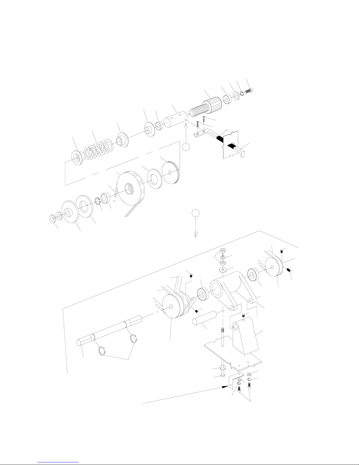
123
121
126
See Figure8,item 15
For refence only.
102
112
111
103
112
111
112
28
31
121
27
29
105
104
30
123
32
104
19
123
118
127
20
111
106
104
113
122
104
3
121
17
20
18
120
12
12
13
123
1
16
131
35
131
FIGURE 4. TENSION ADJUSTMENT AND SENSING ASSEMBLIES
14
125
116
15
102
111
9
Page 32

PARTS LIST, FIGURE 5 HOT-KNIFE AND TENSION LEVER ASSEMBLIES
KEY Q'TY PART NO. DESCRIPTION
FPS-500-050
1 1 4-05010 HEATER ARM UNIT
2 1 4-05020 HEATER HEAD UNIT
3 1 4-05030 TENSION LEVER UNIT
4 1 4-05040 STRAP GUIDE UNIT, ENTRY
5 1 4-05050 STRAP GUIDE UNIT, EXIT
11 1 4-05010-110 Heater arm side plate
12 1 4-05010-120 Heater arm
13 1 4-05010-130 Heater arm screw
14 1 4-05020-140 Heater blade holder
15 1 4-05020-150 Instant heating heater plate
16 1 4-05030-160 Adjustable nut
17 1 4-05030-170 Tension lever
18 1 4-05000-180 Solenoid shaft asse.
21 4 4-05000-210 Spring cover
22 1 4-05000-220 Bracket
23 1 4-05000-230 Feed back arm screw
26 1 4-05050-260 Strap guide, exit
27 1 4-05050-270 Strap guide adjuster, exit
28 1 4-05050-280 Guide nut, M4
29 1 4-05040-290 Strap guide adjuster, entry
30 1 4-05040-300 Strap guide, entry
31 1 4-05030-310 Protuberant sleeve
101 1 200C06090 Hex bolt, M6*90
102 1 200C06100 Hex bolt, M6*100
103 1 200A06050 Socket head cap screw, M6*50
104 1 200E04016 Phillips head machine screw, M4*16
105 5 200A05012 Socket head cap screw, M5*12
106 9 202B05 Lock washer, M5
107 2 201A04 Hex nut, M4
108 5 201A05 Hex nut, M5
109 8 202B04S Lock washer, M4
110 13 201A06 Hex nut, M6
111 7 202B06 Lock washer, M6
112 1 201A08 Hex nut, M8
113 2 202B08 Lock washer, M8
114 1 200E04015 Phillips head machine screw, M4*15
115 2 200A04025 Socket head cap screw, M4*25
116 8 200C05012 Hex bolt, M5*12
117 9 202A0512 Plain washer, M5*12
118 2 202A0613 Plain washer, M6*13
119 8 202C041003 Copper washer, M4*10*0.3
121 1 202A062120 Plain washer, M6*21*2
122 1 2200505006 Heater spring, 0.5*0.5*6.5
123 1 2201011022 Tension spring, long 1*10.8*22
124 2 2210812051 Compression spring, 0.8*12*51
125 2 210A0635ZZ Ball bearing, 635ZZ
126 1 2214024039 Compression spring, 4*24*39
127 1 212AE12 Ring, E-12
129 1 2211610026 Compression spring, 1.6*10*26
130 2 211A0440 Spring pin, 4 dia.*40
131 1 211A0520 Spring pin, 5*20
132 1 103T024-1 Solenoid 24VDC
133 1 227A02016 Rubber washer, (Ф16)
134 8 200C04010S Hex bolt, M4*10
10
Page 33
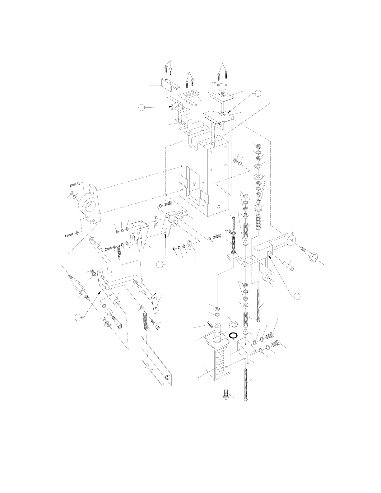
129
109
110
111
116
136
FIGURE 5.HOT-KNIFE AND TENSION LEVER ASSEMBLIES
110
111
29
4
105
116
106
117
111
106
124
21
110
111
102
125
3
103
118
134
119
126
124
110
21
16
111
121
110
131
23
17
106
28
5
27
26
105
115
ITEM 11
SEE FIGURE 1,
30
110
111
110
119
14
107
119
15
134
119
116
133
127
21
107
104
123
18
108
130
11
ITEM 16
SEE FIGURE 9-8
119
109
130
114
108
108
107
109
112
113
31
117
ONLY.SEE FIGURE 2
POSITION REFERENCE*
132
101
22
111
110
2
109
122
125
1
105
13
107
106
12
11
Page 34

PARTS LIST, FIGURE 6-2C CABINET COMPONENTS
KE
Y
Q'T
Y
PART NO. DESCRIPTION
FPS-503-062C
1 1 4-06010 PLASTIC ROLLER BRACKET UNI
T
11 1 4-06200-112 Body
12 1 4-06200-121 Door
14 1 297E0010 Door magnet
15 1 4-06000-151 Plastic package stop
16 1 4-06201-160 Stainless steel top cover
17 2 229D16075CH-GY Wheel swivel 75mm
17.1 2 229E16075CH-GY Wheel fixed 75mm
18 1 4-06000-180 Door holder
19 1 4-06000-191 Sustaining plate
20 1 4-06000-200 Guide plate
21 1 4-06400-211 Hinge
22 1 4-06000-222 Coller
23 1 4-06000-230 Top cover screw
24 1 4-06010-240 Plastic roller
25 1 4-06010-250 Roller pin
26 1 4-06010-260 Roller frame
27 1 4N-01000-470 Liner
28 1 4-09041-121 Switch Dog
29 1 4-06200-291 Control panel
30 4 4-06200-300 Leg
35 1 4-06000-352 Bracket
100 2 202H04 Tooth head washer, M4
101 1 211A0514 Spring pin, 5 dia.*14
102 4 202B06 Lock washer, M6
103 4 202A0613 Plain washer, M6*13
104 18 201H06 Locknut, M6
105 6 200C06020 Hex bolt, M6*20
106 8 202B08 Lock washer, M8
107 2 200A06020 Socket head cap screw,M6*20
108 8 202A0816 Plain washer, M8*16
109 4 200H04012 Truss head machine screw, M4*12
111 2 201A04 Hex nut, M4
114 2 202A061620 Plain washer, M6*16*2
117 2 200A06012 Socket head cap screw, M6*12
118 1 118B CABLE
119 2 200H05020 Truss head machine screw, M5*20
120 8 200C08020 Hex bolt, M8*20
122 2 2210708021 Compression spring, 0.7*8.2*20.5
123 2 201K06 Wn M6
124 2 202B04 Lock washer, M4
126 2 200E05030 Flat head cap screw, M5*30
127 4 202B05 Lock washer, M5
129 2 201A05 Hex nut, M5
130 2 200M06012 Hex bolt with washer, M6*12
132 1 200AR06020 Socket head cap screw,M6*20
12
Page 35
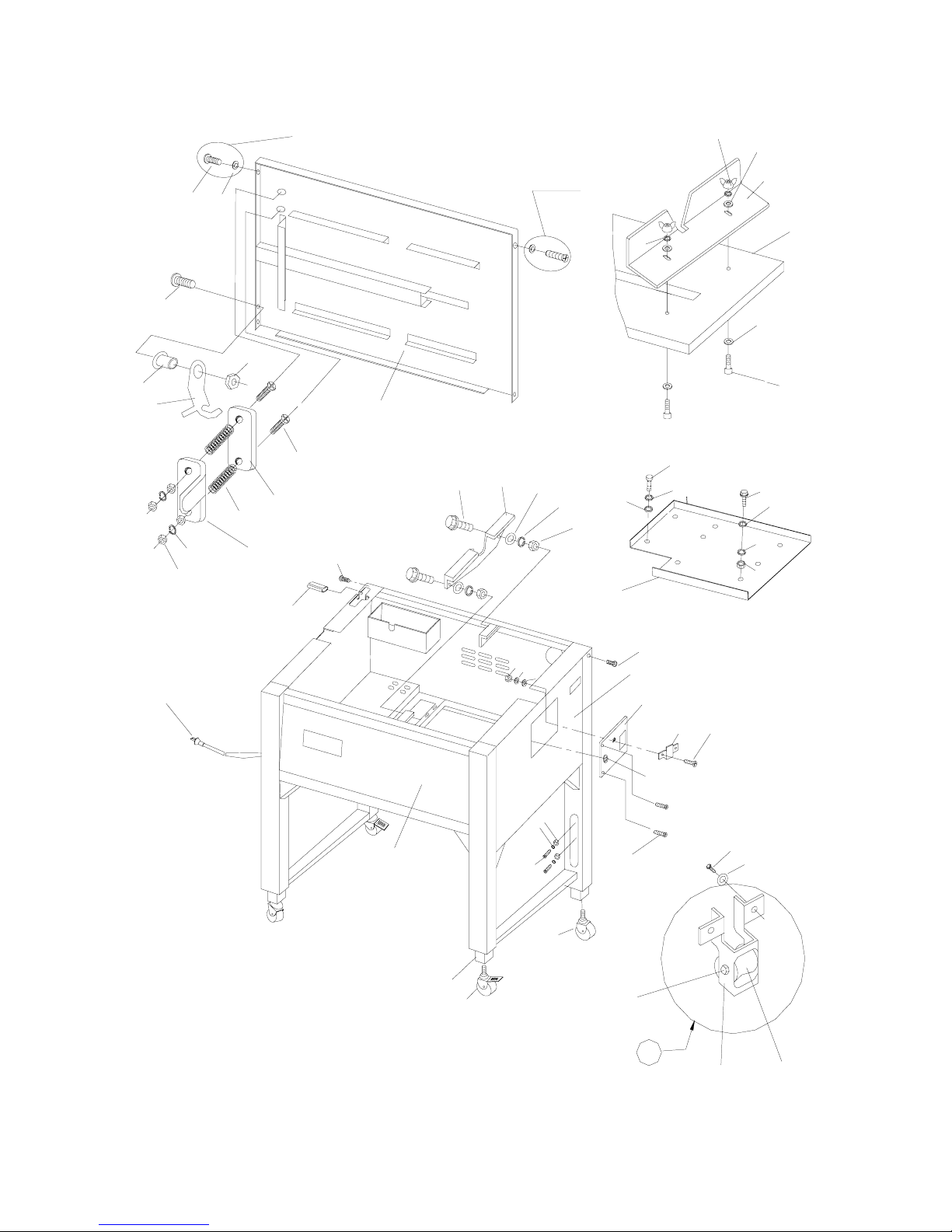
126
122
129
27
28
35
105
104
102
103
23
119
101
16
15
123
114
103
102
104
107
102
103
130
105
1
17
25
24
26
16
1
9
117
102
124
118
21
23
17-1
111
125
1
1
106
108
120
18
12
30
29
127
132
104
22
100
109
OPTION
OPTION
114
FIGURE 6-2C.CABINT COMPONENTS
20
109
103
13
Page 36

PARTS LIST, FIGURE 8-2 DISPENSER ASSEMBLIES
KE
Y
Q'T
Y
PART NO. DESCRIPTION
FPS-503-082
1 1 4-08200 REEL BRAKE UNIT
2 1 4-08210 PLASTIC FLANGE UNIT
11 1 4-08000-110 Pin
12 1 4-08000-120 Plastic roller
13 1 4-08200-130 Roller frame
14 1 4-08200-140 Brake belt
16 1 4-08200-160 Belt pin
17 1 4-08200-170 Brake arm
18 1 4-08200-180 Belt holder plate
19 1 4-08200-190 Reel shaft
20 2 4-07000-110 Plastic flange
22 1 4-07000-130 Reel center claw
24 1 4-07000-150 Y-type washe
r
25 1 4-07000-170 Pin
27 1 4-07000-190 Reel nut handwheel
28 1 4-08200-280 Brake belt tightener
29 1 4-08200-290 Spring pillar
30 1 4-08200-300 Reel brake pulley
31 1 4-06400-330 Plastic bracket
32 1 4-08200-320 Reel brake bracket
33 1 4-08200-330 Brake shaft
37 1 4-08500-370 Brake arm fixed shaft
100 7 202B06 Lock washer, M6
101 7 200A06020 Socket head cap screw, M6*20
102 1 212AS25 Ring, S-25
103 4 200E04025 Phillips head machine screw, M4*25
104 8 201A04 Hex nut, M4
105 14 202A0409 Plain washer, M4*9
106 2 212AE04 Ring, E-4
107 1 212AS10 Ring, S-10
108 2 210A6003ZZ Ball bearing, 6003ZZ
109 1 212AS15 Ring, S-15
110 3 202A0613 Plain washer, M6*13
111 1 212CR08 Snap pin-R08
113 6 200E04016 Phillips head machine screw, M4*16
114 3 202B08 Lock washer, M8
115 1 202A0816 Plain washer, M8*16
116 3 201A08 Hex nut, M8
117 1 200A08030 Socket head cap screw, M8*30
118 1 200A06016 Socket head cap screw, M6*16
119 5 201A06 Hex nut, M6
120 8 202B04 Lock washer, M4
121 4 200C06025 Hex bolt, M6*25
122 8 202A061620 Plain washer, M6*16*2
123 2 212AS20 Ring, S-20
125 1 2201213047 Brake spring, 1.2*13*47
14
Page 37

PARTS LIST,FIGURE 9-5 ELECTRICAL COMPONENTS
KE
Y
Q'TY PART NO. DESCRIPTION
FPS-500-095
1 1 4-09010 SMOKE FAN UNIT
2 1 4-09020 INSTANT HEATING TRANSFORMER UNIT,110V
12 Option 4-09041-120 Switch holder
13 1 4-09010-132 Fan bracket
14 1 4-09010-143 Protect cover
15 1 4-09010-151 Protect cover bracket
16 2 4-09020-160 Instant heating cable
17 2 4-09020-170 Insulating tube
18 1 4-09020-180 Transformer foot
19 1 4-09000-190 Heating transformer cover
106 10 202B05
Lock washer, M5
107 8 201A04 Hex nut, M4
112 6 202A0510 Plain washer, M4
115 6 200E04012 Phillips head machine screw, M4*12
116 6 202B04 Lock washer, M4
121 1 108BK500 Potentiometer, adjustable VR-500K(24D)
122 1 153K0617B Knob
124 1 116AD024 Smoke fan, 24VDC 80*80
125 1 103A1101 Instant heating transformer, 110V-1V
125 103A2201 Instant heating transformer, 220V-1V
125 103A2401 Instant heating transformer, 240V-1V
126 Option 104Y1638 Cut safety switch XK-1099
127 1 153K0619R Knob
128 1 PC-FP-24D03-11060 Heating PC board asse. FP-24D03 110V/60HZ
128 PC-FP-24D03-23050 Heating PC board asse. FP-24D03 220-230V/50HZ
128 PC-FP-24D03-22060 Heating PC board asse. FP-24D03 220V/60HZ
128 PC-FP-24D03-24050 Heating PC board asse. FP-24D03 240V/50HZ
129 1 254A0011 Lable
130 2 200E05016 Phillips head machine screw, M5*16
132 2 202B05 Lock washer, M5
134 4 202A0510 Plain washer, M5*10
136 2 201A05 Hex nut, M5
138 4 200C04010 Hex bolt, M4*10
16
Page 38
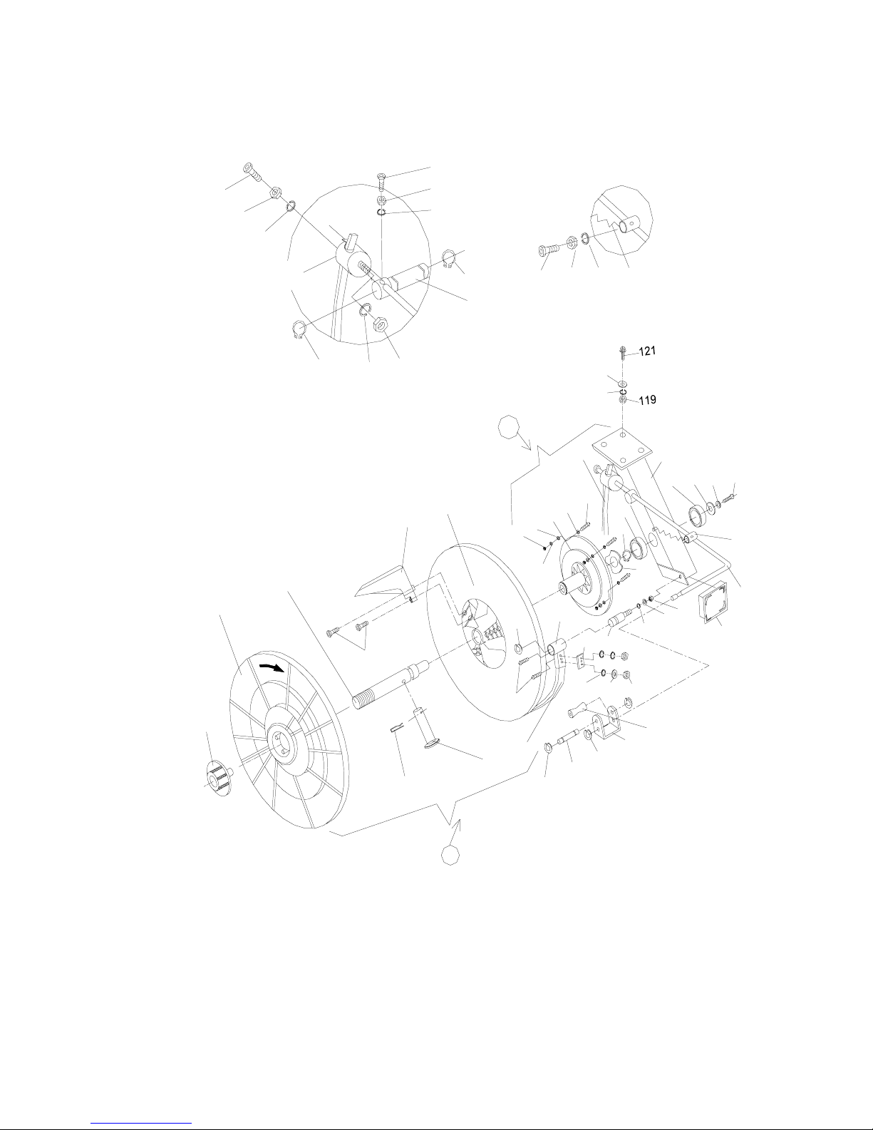
1
6
2
7
FIGURE 8-2.DISPENSER ASSEMBLY
1
2
0
1
1
1
0
6
2
1
1
1
1
0
1
2
5
1
4
1
0
3
1
3
7
1
0
8
2
4
1
1
4
1
0
8
1
0
2
1
7
2
9
1
0
1
1
4
1
1
0
3
2
1
2
8
1
0
1
1
1
9
1
0
0
1
1
9
1
0
0
1
2
5
1
0
5
1
0
4
1
1
5
1
1
6
1
2
0
38
1
0
0
1
2
2
31
1
0
7
1
3
1
2
1
8
2
0
1
1
6
3
3
1
1
4
1
1
7
1
2
3
1
0
1
1
0
5
1
1
3
1
9
2
2
1
0
9
2
8
2
0
1
0
5
1
0
4
3
0
1
2
3
1
2
7
1
2
6
15
Page 39
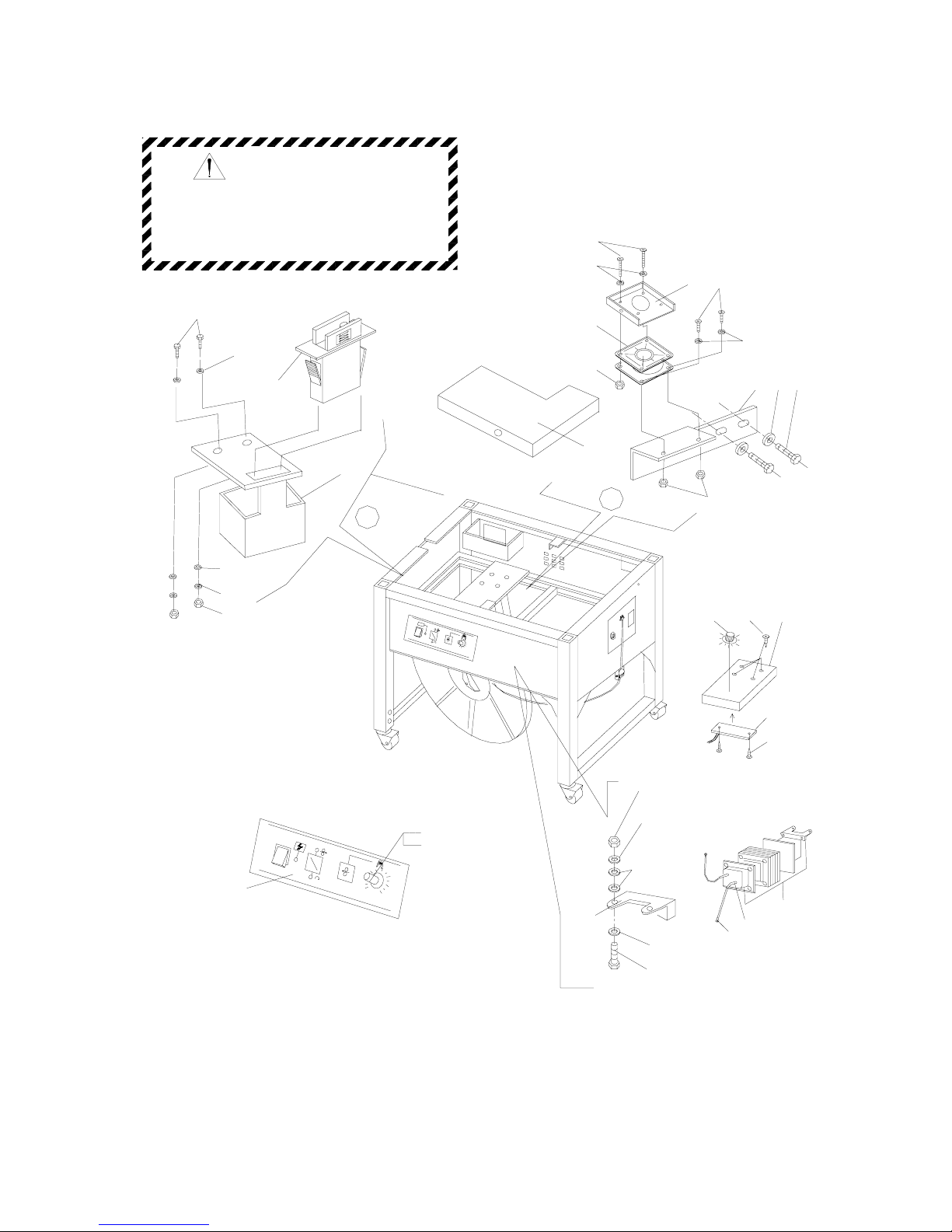
FIGURE 9-5.ELECTRICAL COMPONENTS
134
136
132
134
130
12
126
do this can affect a tool's operation
and present a safety hazard.
and replaced if worn or broken.Failure to
All parts must be periodically inspected
WARNING
129
2
1
122
121
102
128
14
127
19100
107
107
124
13 138139
106
115
106
115
15
o
p
t
i
o
n
1
2
17
16
125
106
138
112
18
106
107
17
Page 40

PARTS LIST, FIGURE 10-2 CONTROL BOX ASSEMBLY
KE
Y
Q'TY PART NO. DESCRIPTION
FPS-500-102
11 1 4-10200-110 Control bo
x
12 1 4-10200-120 Control box cove
r
17 1 PC-FP-30B01 Control PC board asse. FP-30B01
102 1 103B1122035 Transformer, 110V/22V 35VA
102 1 103B2322035 Transformer, 220-230V/22V 35VA
102 1 103B2422035 Transformer, 240V/22V 35VA
104 1 115N0630 Fuse seat,(Φ6.3*30)
1 115ASL-0630-02 Circuit Protector, 2A-6*30mm 110V
1 115ASL-0630-02 Circuit Protector, 2A-6*30mm 220V
105 1 115N0630 Fuse seat,(Φ6.3*30)
1 115ASL-0630-03 Circuit Protector, 3A-6*30mm 110V
1 115ASL-0630-03 Circuit Protector, 3A-6*30mm 220V
106 1 115N0630 Fuse seat,(Φ6.3*30)
1 115ASL-0630-15 Circuit Protector, 15A-6*30mm 110
V
108 4 200E03006 Phillips head machine screw, M3*6
109 4 153J002 Speed clamp
110 2 200A06016 Socket head cap screw, M6*16
111 4 202A0612 Plain washer,M6*12
112 4 200F03012 Flat head cap screw, M3*12
113 8 202B03 Lock washer, M3
114 8 201A03 Hex nut, M3
115 1 PC-FP-30S Control PC Board Asse.FP-30S
116 1 108BK500 Potentiometer, adjustable VR-500K(24D)
122 1 153K0619
R
Knob
18
Page 41
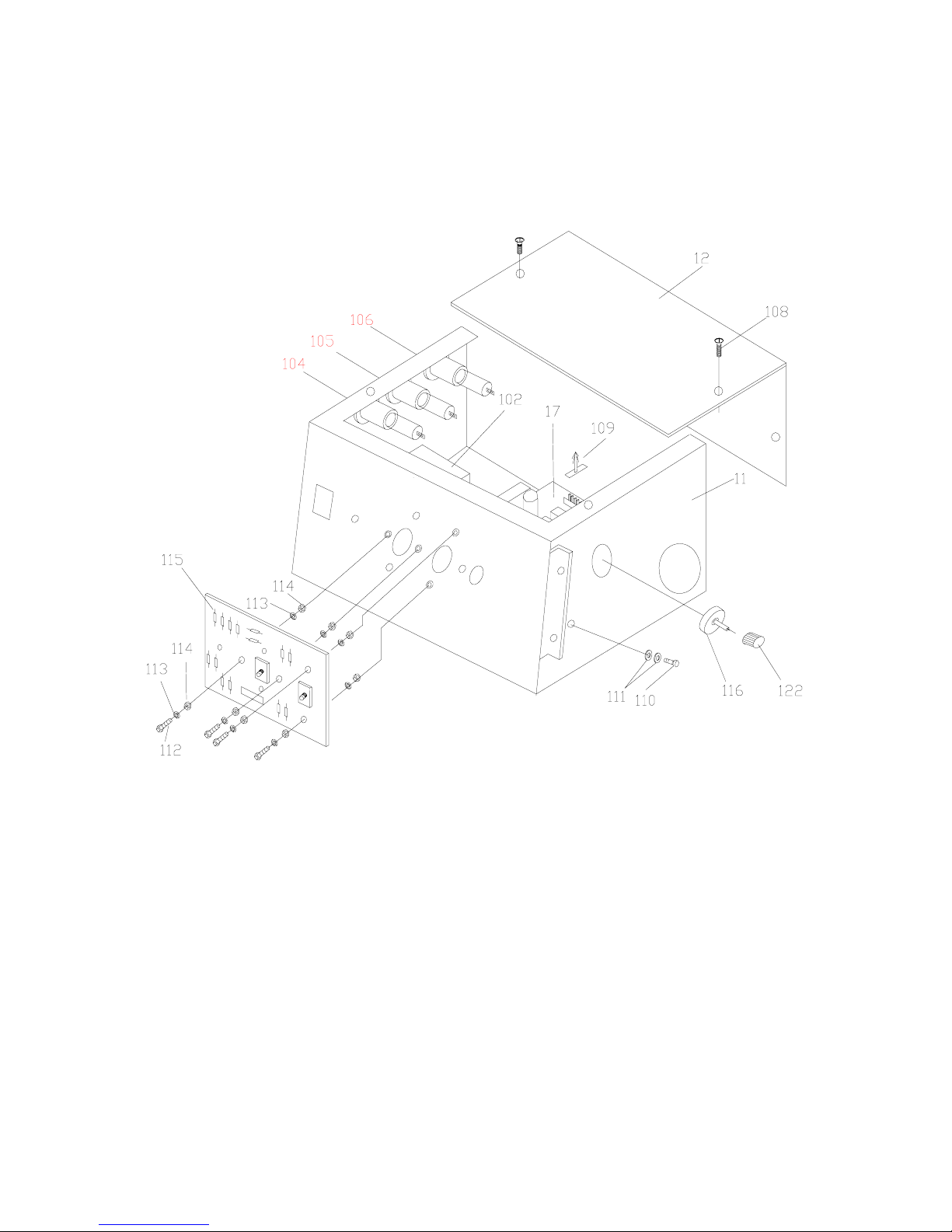
FIGURE10-2. CONTROL BOX ASSEMBLY
19
Page 42
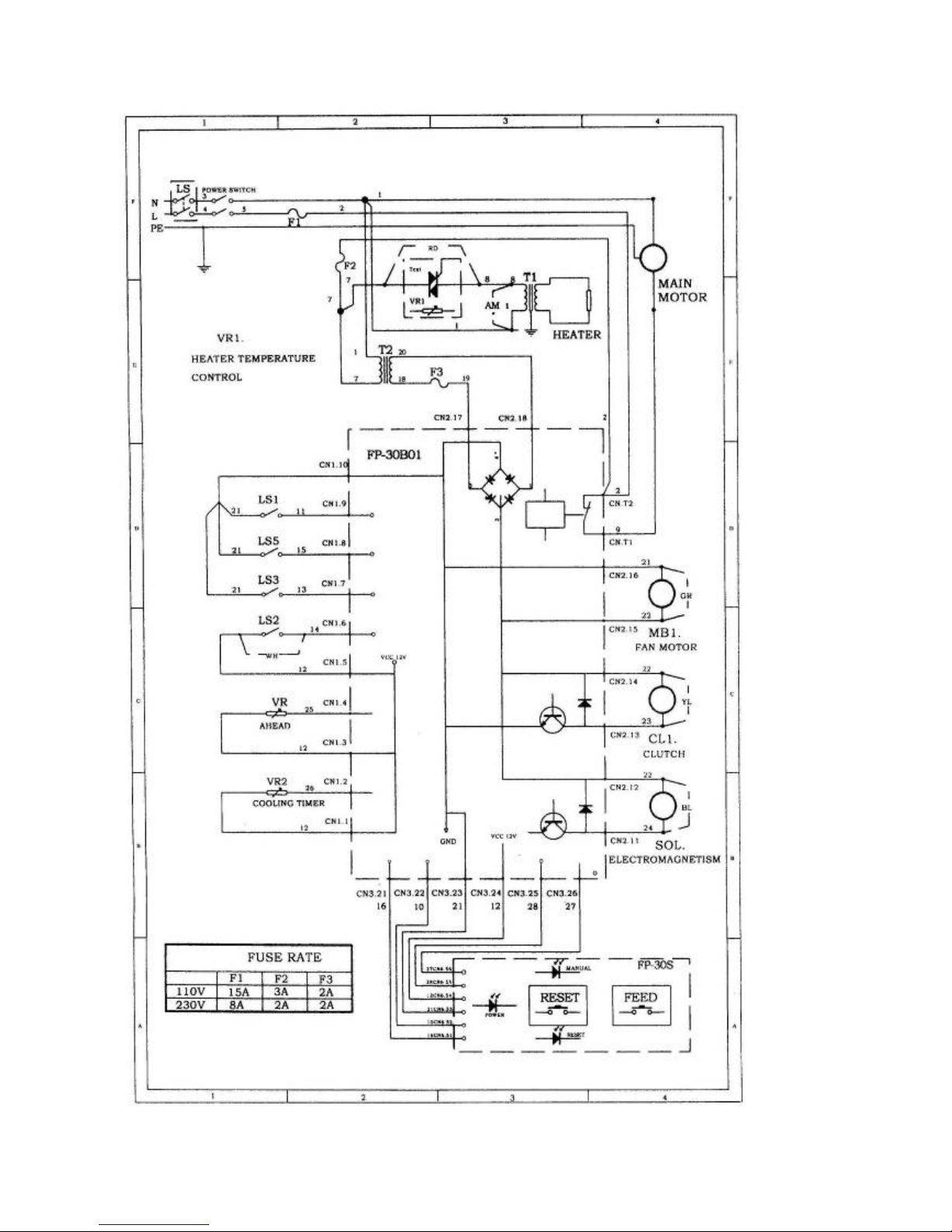
20
Page 43
 Loading...