

Page 1

USER GUIDE
TKG100
Digital Ultrasonic Thickness
Gauge
TKG150
Digital Ultrasonic Thickness
Gauge with Datalogger
Page 2

Extech Instruments .
2 TKG100_TKG150 Ultrasonic Thickness Gauge User Guide v2.8 11/13 2
WARRANTY
FLIR Systems, Inc. warrants this Extech Instruments brand device to be free
of defects in parts and workmanship for two years from date of shipment (a six
month limited warranty applies to sensors and cables). If it should become
necessary to return the instrument for service during or beyond the warranty period,
contact the Customer Service Department for authorization. Visit the website
www.extech.com for contact information. A Return Authorization (RA) number
must be issued before any product is returned. The sender is responsible for
shipping charges, freight, insurance and proper packaging to prevent damage in
transit. This warranty does not apply to defects resulting from action of the user
such as misuse, improper wiring, operation outside of specification, improper
maintenance or repair, or unauthorized modification. FLIR Systems, Inc. specifically
disclaims any implied warranties or merchantability or fitness for a specific purpose
and will not be liable for any direct, indirect, incidental or consequential damages.
FLIR‟s total liability is limited to repair or replacement of the product. The warranty
set forth above is inclusive and no other warranty, whether written or oral, is
expressed or implied.
The information in this document is subject to change without notice and describes
only the product defined in the introduction of this documentation. This document
is intended for the use of Extech Instruments customers only (a Flir Systems, Inc.
brand) for the purposes of the agreement under which the document is submitted,
and no part of it may be reproduced or transmitted in any form or means without
the prior written permission. For information address: Flir Commercial Systems,
Inc. 9 Townsend West, Nashua NH, 03063 U.S.A.
The information or statements given in this document concerning the suitability,
capacity, or performance of the mentioned hardware or software products cannot
be considered binding but shall be defined in the agreement made between Flir
Systems and the customer. However, Flir Systems has made all reasonable efforts to
ensure that the instructions contained in the document are adequate and free of
material errors and omissions. Flir Systems will, if necessary, explain issues which
may not be covered by the document.
Other product names mentioned in this document may be trademarks of their
respective companies, and they are mentioned for identification purposes only.
Copyright 2013 Flir Systems, Inc., All Rights Reserved
Printed in the United States of America
Page 3

3
LIABILITY
Ultrasonic testing is a function of using the proper equipment
(electronics, transducer, cable and couplant combination) for the
inspection and a qualified operator who knows how to use this manual,
the instruments and all calibration procedures. The improper use of this
equipment, along with the improper calibration can cause serious
damage to components, factories, facilities, personal injury and even
death.
ALL FLIR SYSTEMS ULTRASONIC THICKNESS GAUGES ARE
NOT INTRINSICALLY SAFE AND SHOULD NOT BE USED IN
ANY HAZARDOUS OR EXPLOSIVE AREAS.
It is understood that the operator of this equipment is a well-trained
inspector qualified by either their own company or another outside
agency to issue Ultrasonic Level I, 40 hour class room training in
Ultrasonic Theory. Flir Systems and any of its employees or
representatives shall not be held responsible for improper use of this
equipment for its intended use. Proper training, a complete
understanding of Ultrasonic wave propagation, thorough reading of this
manual, proper transducer selection, correct zeroing of the transducer,
correct sound velocity, proper test blocks, proper cable length, proper
couplant selection all play a factor in successful ultrasonic thickness
gaging. Special care should be taken when test pieces have rough or
painted surfaces, particularly those applications where the test piece is
thin to begin with as doubling of the echoes is possible even if the
transducer is capable of measuring the desired thickness. As transducers
wear or heat up, results can be either too thin due to a lack of sensitivity
as a result of wear or too thick due to heating up of the transducer,
referred to as “drift.”
Page 4

Extech Instruments .
4 TKG100_TKG150 Ultrasonic Thickness Gauge User Guide v2.8 11/13 4
Table of Contents
Table of Contents ........................................................................................ 4
1 Getting Started ......................................................................................... 7
About the TKG Series ............................................................................. 7
Probe Zero................................................................................................ 8
Keypad Functions .................................................................................. 10
Function Keys ........................................................................................ 11
Display Screen ....................................................................................... 11
Battery Power ......................................................................................... 13
Monitoring the Battery from the Display ........................................ 13
Replacing the Batteries ................................................................... 13
2 Basic Gauge Operations ...................................................................... 14
Power on the Gauge ............................................................................. 14
Performing a Reset (TKG100) ............................................................. 16
Performing a Reset (TKG150) ............................................................. 17
About Screen ......................................................................................... 19
3 Calibrating the Gauge/Making Measurements ................................ 20
Velocity Calibration Only ....................................................................... 20
Velocity and Zero Calibration ............................................................... 21
Zero Calibration Only ............................................................................ 22
Delay Line Calibration ........................................................................... 23
Page 5

5
Automatic Zero ....................................................................................... 24
Measurement Mode with a Datalogger (TKG150) ....................... 26
Measurement Mode without a Datalogger (TKG100) .................. 27
4 Measurement Mode Setup Options ................................................. 29
Using the Clock ...................................................................................... 31
Setting LCD Contrast ............................................................................ 33
Understanding a LOS Reading ............................................................ 33
Using the Hold Option ........................................................................... 34
Using the Fast Option ........................................................................... 35
Using the Gain Option (TKG150 only) ................................................ 38
Using the Diff Option ............................................................................. 39
Using the Alarm Option ......................................................................... 40
‘Vibra’ Alarm (TKG150 only) ........................................................... 44
Using the Echo-to-Echo Option (TKG150 only) ................................. 47
5 Special Gauge Functions ..................................................................... 48
Using the Save Option (TKG150 only) ................................................ 48
Using the Freeze Option ....................................................................... 50
6 Using Datalogger Directory Mode (TKG150) ................................... 55
Selecting a Custom Linear File ...................................................... 63
Selecting a Custom Grid File .......................................................... 63
Reviewing a File .................................................................................... 65
Reviewing a Linear File ................................................................... 66
Reviewing a Grid File ...................................................................... 67
Renaming a File ................................................................ ..................... 67
Page 6

Extech Instruments .
6 TKG100_TKG150 Ultrasonic Thickness Gauge User Guide v2.8 11/13 6
Copying a File ........................................................................................ 71
Deleting a File ........................................................................................ 74
7 Technical Specifications ...................................................................... 76
8 Software Options ................................................................................... 79
B-Scan (TKG150 only) .......................................................................... 80
9 Technical Assistance ............................................................................ 81
Page 7

7
1 Getting Started
About the TKG Series
The TKG100 and TKG150 are portable, digital,
handheld thickness gauges. The TKG series of ultrasonic
thickness gauges are specifically designed to measure the
remaining wall thickness of primarily steel structures.
Vibralarm (vibrates gauge below/above
minimum/maximum thickness value)
Illuminating keypad for easy to view go-no go
thickness values (patent pending)
Automatic transducer replacement intelligence
built in (patent pending)
Unique, programmable left-hand/right-hand
operation (patent pending)
Up to 200 hour battery life with 2 AA batteries
Small, easy to hold, ergonomic, custom molded,
durable case with rubber keypad
Automatic zero capability
Gain boost
Page 8

Extech Instruments .
8 TKG100_TKG150 Ultrasonic Thickness Gauge User Guide v2.8 11/13 8
The TKG100 is a base gauge offering a simple user
interface packaged in the same custom molded highdensity plastic case with rubber keypad as the other more
sophisticated models. This gauge offers reliable, accurate
thickness readings on mostly steel structures with access
to only one side.
The TKG150 contains all the same features of the
TKG100 plus:
50,000 (expandable to 100,000) reading
datalogger capacity with complete setup
tracking
Three pre-set files for linear, grid (row advance)
and grid (column advance)
Echo-to-Echo
B-scan
Probe Zero
When turning on the TKG100 or TKG150 (for the sake
of this manual, with the exception of the datalogger, Bscan, and Echo-to-Echo features, the two model
numbers are interchangeable for the basic operation and
calibration), the gauge does an automatic zeroing of the
transducer (after the user selects the transducer from the
list) thus eliminating the need for an on-block zero. The
TKG100 and TKG150 will electronically zero the
transducer upon power up and at a particular time during
normal operation. This feature ensures the transducer is
Page 9

9
working in accordance with electronic zeroing
procedures. This feature is particularly important on high
temperature materials and when the transducer becomes
worn.
Important Notice: Please make sure the transducer
is not coupled to the test piece when the gauge is first
turned on and that there is no couplant on the end of
the transducer. The transducer should also be at room
temperature, clean without any noticeable wear.
Page 10
Extech Instruments .
10 TKG100_TKG150 Ultrasonic Thickness Gauge User Guide v2.8 11/13 10
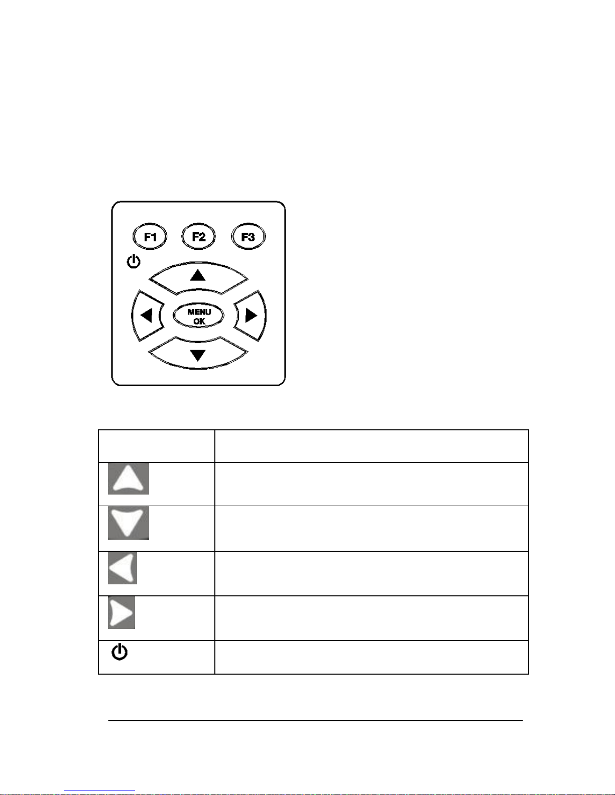
Keypad Functions
The figure below shows the full keypad of the TKG
Series thickness gauges. Refer to the following table that
lists the function of each key on the keypad.
Key
Function
Up arrow key
Down arrow key
Left arrow key
Right arrow key
On/Off symbol (under the F1 key)
Page 11

11
MENU/OK key
F1 key
F2 key
F3 key
Function Keys
Function keys, or F keys, such as F1, F2, and F3 have
various gauge functions and may change depending on
the display screen. View the bottom of the display screen
for the function that corresponds with the appropriate F
key. For example, F1 may correspond with the Save
function, F2 with the Freeze function, or F3 with the
Directory function (Dir).
Display Screen
The gauge has a graphic style Liquid Crystal Display
(LCD). Viewing the screen is best from straight above or
slightly below the surface rather than from side to side. If
external temperatures are below 32F (0C), the display
may be slow to update information.
Page 12
Extech Instruments .
12 TKG100_TKG150 Ultrasonic Thickness Gauge User Guide v2.8 11/13 12
The TKG series is designed to show the parameters
selected in the center of the display screen.
The top part of the display screen for TKG150 model
shows the File name, ID number, AA, and 0001 for grid
column and row. The lower part of the display acts as an
interactive tool that allows you to decide how you want
to proceed with the information that is displayed on the
screen. The middle part of the screen shows the
thickness value, In, mm or usec, Echo-to-Echo symbol,
LOS for loss of signal, Freeze, Fast, Min or Max, Alarm
indicator, Differential mode, Low, Med or High gain and
percent remaining battery life.
F1 F2 F3
F1 F2 F3
Page 13

13
Battery Power
Monitoring the Battery from the Display
The TKG series constantly displays the percent battery
life on the bottom right hand corner of the display
screen. When the gauge gets below 20 %, the indicator
will flash.
Replacing the Batteries
To replace the batteries, unscrew the battery door on the
bottom of the gauge and slide out the two “AA”
batteries. Replace with two new “AA” batteries paying
attention that both positive ends are facing towards the
top of the gauge.
Page 14
Extech Instruments .
14 TKG100_TKG150 Ultrasonic Thickness Gauge User Guide v2.8 11/13 14
2 Basic Gauge Operations
Power on the Gauge
To power on any of the TKG series thickness gauges
follow these steps:
1. Press and hold the F1 key for more than 3
seconds. The power symbol is under the F1 key
printed on the keypad as shown below.
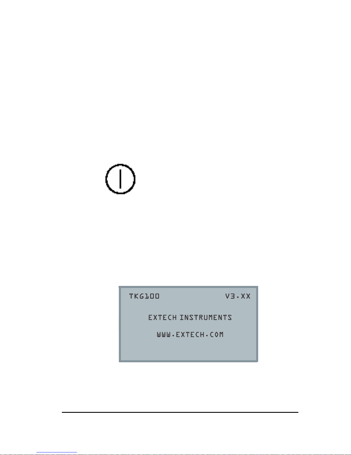
2. The following (or similar) will appear on the
display screen of the thickness gauge:
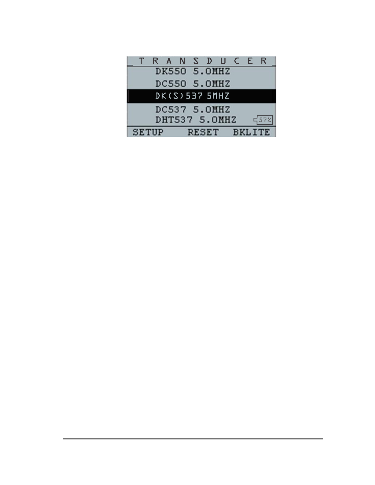
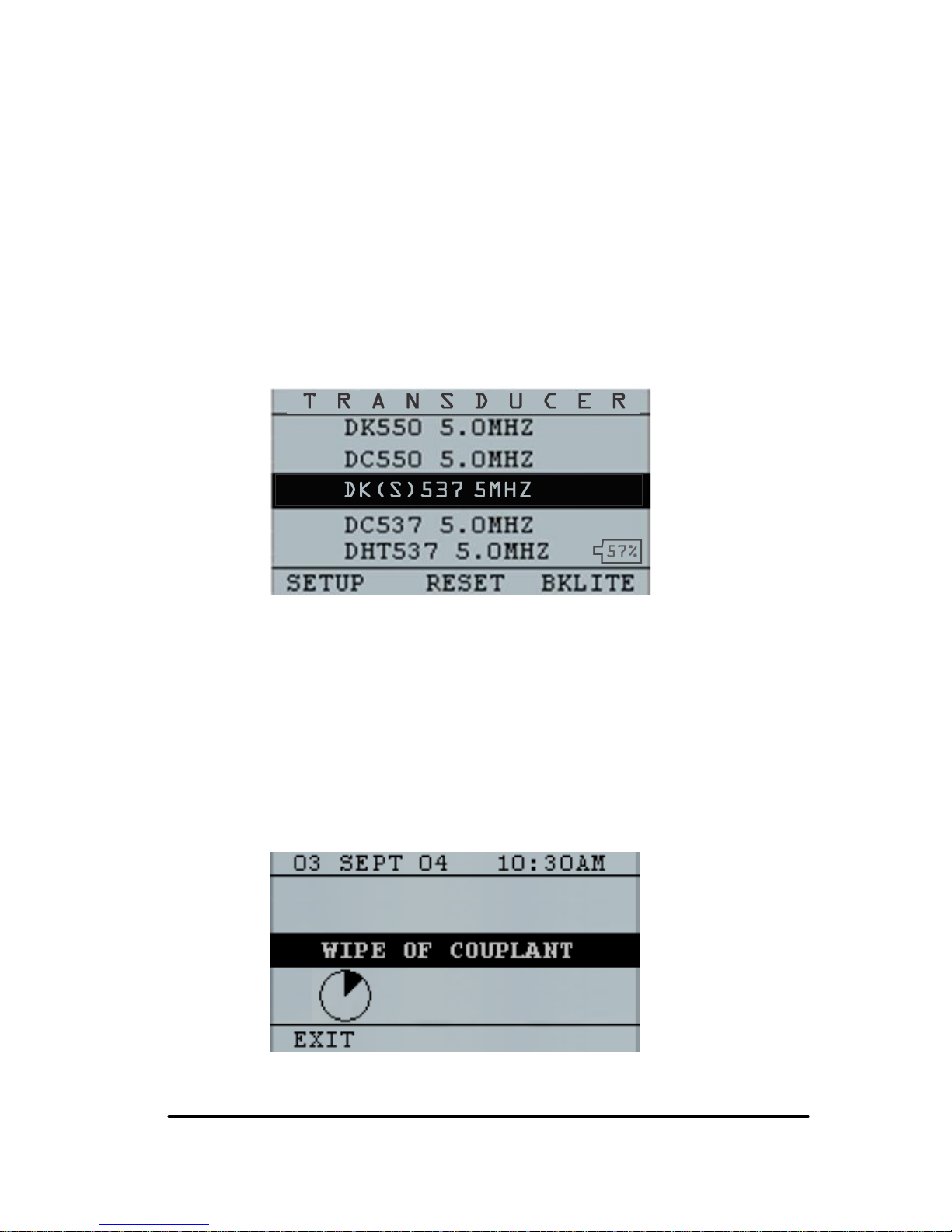
3. The next screen that appears automatically is
the transducer selection screen also referred to
as Home screen in the manual.
Power symbol
under the F1 key
Page 15
15
4. Use the up and down arrow keys to select a
transducer and press OK key. (Please note that
the transducer selection will automatically
display the transducer last used prior to shut
off.
5. Press F1 to select the Setup option.
6. Press F2 to select the Reset option.
7. Press F3 to select the Bklite option.
Page 16
Extech Instruments .
16 TKG100_TKG150 Ultrasonic Thickness Gauge User Guide v2.8 11/13 16
Performing a Reset (TKG100)
You can reset the TKG100 gauge settings back to the
default settings by performing a gauge reset.
Note: Performing a reset permanently deletes all of
the saved parameters from the gauge and replaces the
settings with default values.
To perform a reset, follow these steps:
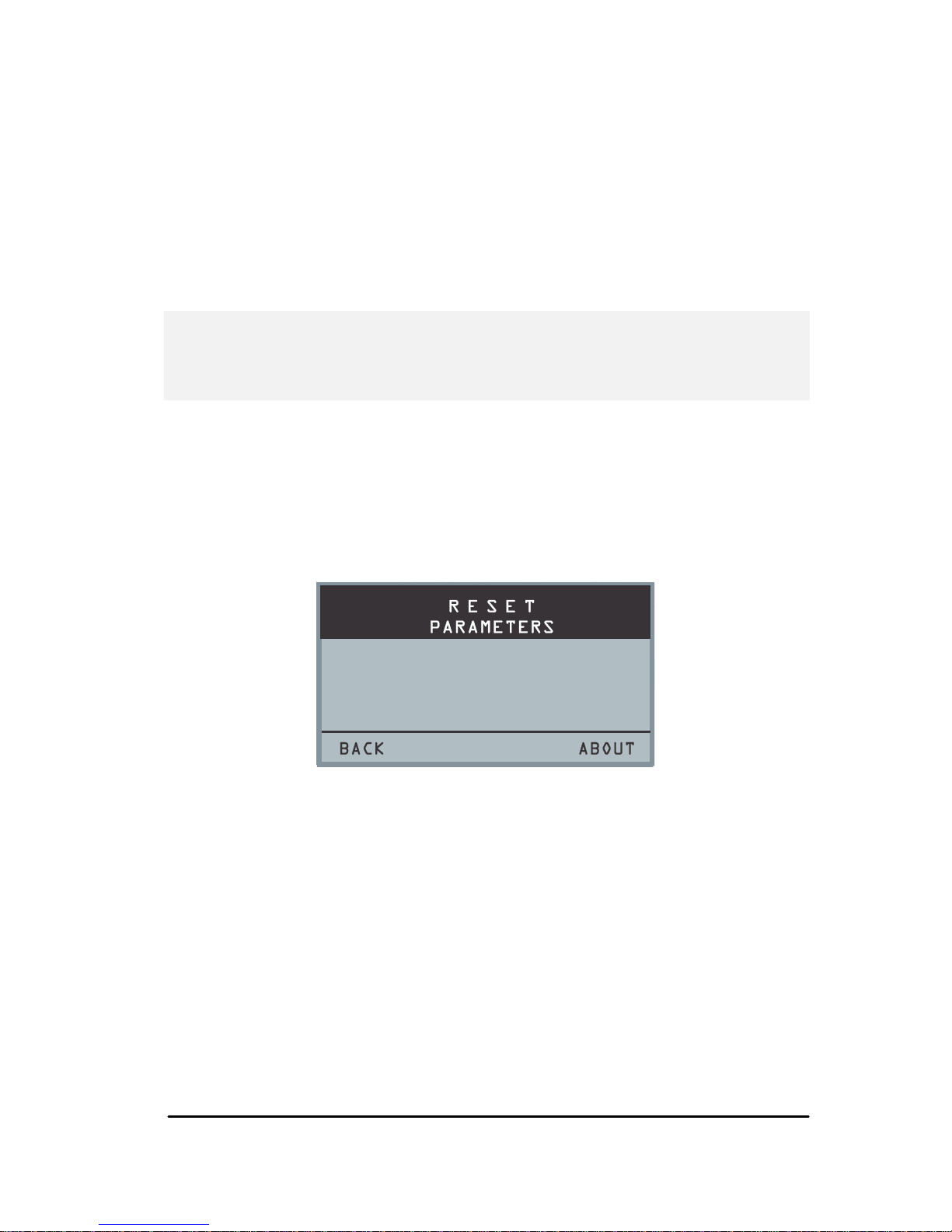
1. From the Home screen (transducer select
screen), press the F2 Reset key. The following
Reset screen appears:
2. Press the OK button and the ARE YOU
SURE? Prompt will appear. Press YES, NO, or
BACK using the F1 F2 F3 function buttons as
desired.
Page 17
17
Performing a Reset (TKG150)
You can reset both the TKG150 DATABASE and
PARAMETER settings back to their default settings in
one gauge reset or you can reset the PARAMETER and
DATABASE data individually.
Note: Performing a reset permanently deletes all of
the saved parameters from the gauge and replaces the
settings with default values.
To perform a reset, follow these steps:
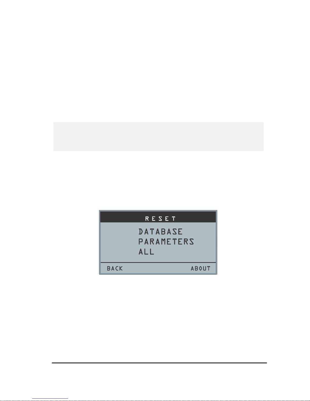
1. From the Home screen (transducer select
screen), press the F2 Reset key. The following
Reset screen appears:
2. Use the up and down arrow keys to select
DATABASE, PARAMETERS, or ALL and
then press MENU/OK.
3. The ARE YOU SURE? Prompt will appear.
Press YES, NO, or BACK using the F1 F2 F3
function buttons as desired.
Page 18

Extech Instruments .
18 TKG100_TKG150 Ultrasonic Thickness Gauge User Guide v2.8 11/13 18
4. Note that performing a Database Reset clears
all the files in the database and keeps the first
three: Linear, Row increment and Col
increment database files with cleared readings.
All the user created files in the database will be
cleared and deleted.
5. After performing a Reset, the Home screen
appears automatically.
Backlight
The backlight can be turned On or Off by pressing F3 –
Bklite. Backlight can also be turned On, Off or set on
Auto using the Bklight option in the Setup Menu.
Note: Leaving the backlight on will reduce battery life.
If you set the backlight to Auto, the backlight will turn
on during active readings and hold for 15 seconds or
unless otherwise specified.
Note: If the backlight is set to Auto and you have the
gauge in Hold mode, the backlight will shut off after 15
seconds. If you would like the hold to remain lit, then
you must enable the backlight on instead of using
Auto.
Page 19
19
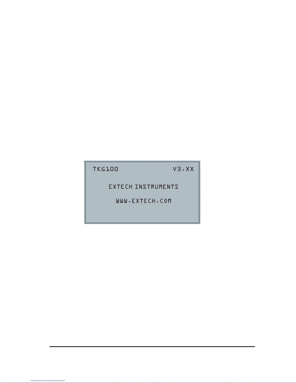
About Screen
You can find information about any of the TKG series
thickness gauges such as the model number, version
number and contact information from the gauge‟s About
screen. To go to the About Screen, follow these steps:
1. From the Home screen (transducer select
screen), press the F2 – Reset key. The Reset
screen will appear.
2. Press the F3 – About key. The following About
screen appears.
3. Press the F1 – Exit key to return to the Reset
selection screen.
Page 20

Extech Instruments .
20 TKG100_TKG150 Ultrasonic Thickness Gauge User Guide v2.8 11/13 20
3 Calibrating the Gauge
Calibrating is the process of adjusting the gauge for a
specific material and transducer before testing material to
make sure that all measurements are accurate. You must
always calibrate before measuring material for standard
accuracy.
To measure a thickness of unknown material you need to
know the velocity of the sound in the unknown material.
To find the velocity of the sound you can use one of the
following methods:
Velocity calibration only
Velocity and zero calibration
Zero calibration only
Delay line calibration
Velocity Calibration Only
If you are working with a test piece of known thickness
but unknown material, then you can calibrate the velocity
of the sound in the unknown material by measuring the
time of flight from main-bang to the first back echo. By
using the known thickness you can calculate velocity of
the sound for the unknown material.
To perform any calibration, first go to the measure mode
and press Menu/OK. Then select the Calibration option
from the Menu screen and press OK. The following
Calibration mode screen (or similar) should appear. To
Page 21
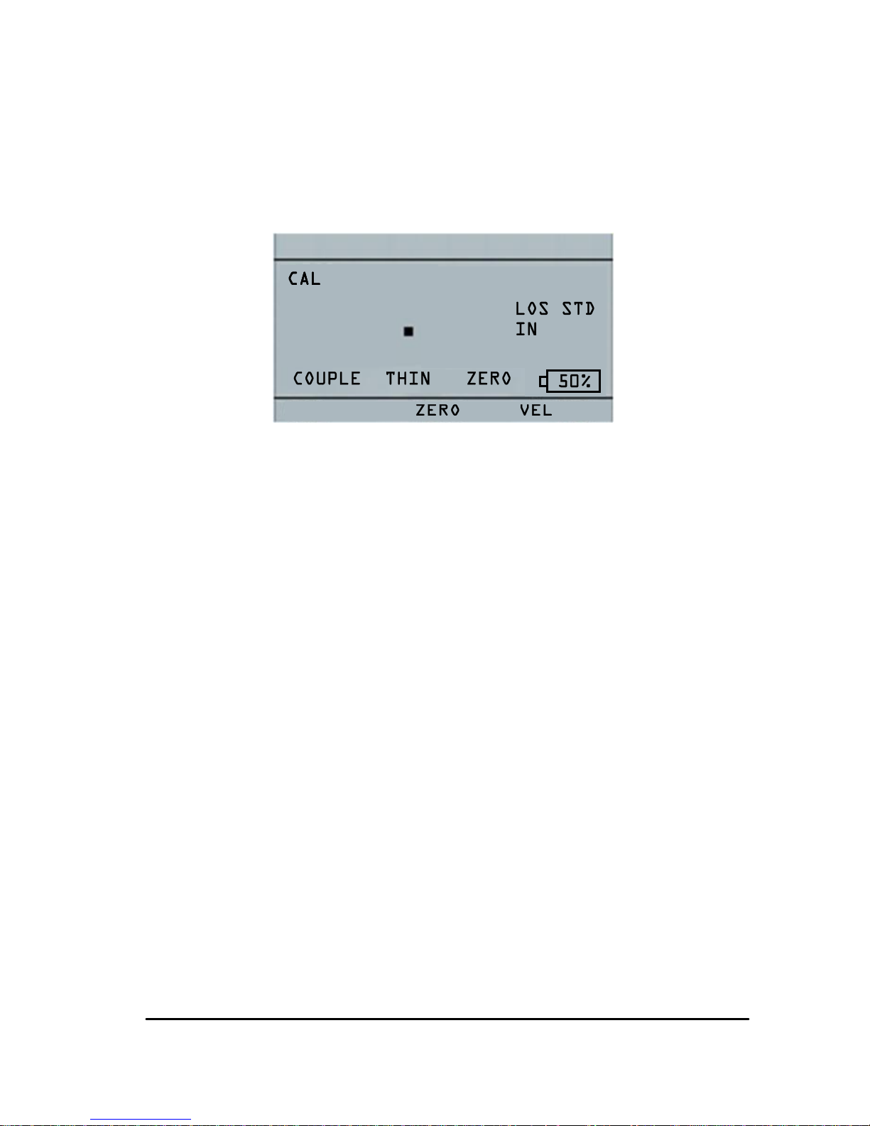
21
exit the calibration screen without performing any
calibration, press OK. To proceed to the Velocity
calibration, follow the following instructions.
Cal screen for TKG100 non-datalogger version
While measuring the thicker step, select VEL by pressing
F3. After selecting VEL, you can take the transducer off
the test block. If the displayed measurement is different
than the known value of the step, use the up or down
arrow key to adjust the displayed value to the known
value of the step. Press OK to perform the calibration.
The unit will briefly display the calibrated velocity value
in the top of the screen and then return to measure
mode.
Velocity and Zero Calibration
If you have a test step block of known thicknesses but
unknown material, then you can calibrate the zero and
velocity of the sound in the unknown material by
measuring the time of flight from the main-bang to the
first back echo for thinner step and thicker step.
Page 22

Extech Instruments .
22 TKG100_TKG150 Ultrasonic Thickness Gauge User Guide v2.8 11/13 22
To calibrate both: velocity and zero at the same time first
go to the Calibration mode as shown in Velocity
Calibration Only section. While measuring the thicker
step, select VEL by pressing F3. After selecting VEL you
can take the transducer off the test block. If the displayed
value is different than the known value of the step, adjust
the value by pressing up or down arrow keys and press
F1/CAL. Then while measuring the thinner step select
ZERO by pressing F2. After selecting ZERO you can
take the transducer off the test block. If measured value
is different than the known value of the step, adjust the
measured value by pressing up or down arrow key and
then press OK. The unit will briefly display the calibrated
zero value and then return to Measure mode. Note that
the order of Velocity and Zero calibration could be
reversed. If Velocity calibration is performed after Zero
calibration, the calibrated velocity value will be displayed
at the end of the calibration process.
Zero Calibration Only
If you have a test step block of known thickness and
known velocity of sound in the material, then you can
calibrate the zero by measuring the time of flight from
main-bang to the first back echo for the thinner step.
The calibrated zero is the calculated zero minus the
measured zero.
To accurately measure a thickness of unknown material
you need to know the velocity of the sound in the
unknown material and the errors introduced by the cable
Page 23

23
and electronics. This is called delay line and zero
calibrated value for the transducer.
To perform a zero calibration, go to the Cal mode as
shown in Velocity Calibration Only section. Then while
measuring the thinner step, select ZERO by pressing F2.
After selecting ZERO, you can take the transducer off
the test block. If the displayed measurement is different
than the known value of the step, use the up or down
arrow key to adjust the displayed value to the known
value of the step. Press OK to perform the calibration.
The unit will briefly display the calibrated zero value in
the top of the screen and then return to measure mode.
Delay Line Calibration
Delay line calibration is done every time the thickness
gauge is powered on and a transducer is selected, or
when a different transducer is selected during normal
operation.
Delay line calibration is performed by measuring the
echo of the transducer itself when it is not placed on any
material and there is no couplant on the transducer
surface.
Under normal usage, the surface of the transducer wears
over time, which reduces sensitivity of the transducer.
When you power on any of the TKG series thickness
gauges and select a transducer, the gauge performs
automatic calculations and warns you (patent pending) if
Page 24
Extech Instruments .
24 TKG100_TKG150 Ultrasonic Thickness Gauge User Guide v2.8 11/13 24
the sensitivity of the transducer is too low and whether
the transducer should be replaced.
Automatic Zero
To perform an Automatic Zero or Auto Zero, you must
first select a transducer option from the Transducer
selection screen and press the Menu/OK key.
To continue the Auto Zero, follow these steps:
1. Follow the instructions given on each display
screen; the first of which will prompt you to
wipe off any couplant from the transducer and
wait three seconds. The waiting time is shown
in the changing pie-clock graphic on the display
screen.
Page 25
25
2. After three seconds the gauge automatically
begins to zero the transducer. During the delay
line calibration a screen appears displaying the
message “Performing Auto Zero”.
3. A warning message will appear on the display
screen if the delay line is below the acceptable
limit for accurate thickness measurements. You
will need to replace the transducer or select the
F1 key to acknowledge the warning message
and continue using the same transducer, which
may have a worn surface.
4. After three seconds or after acknowledging the
warning message, the display shows the
instrument parameters for 3 seconds before
going to
Measurement
mode.
Page 26
Extech Instruments .
26 TKG100_TKG150 Ultrasonic Thickness Gauge User Guide v2.8 11/13 26
4 Measurement Mode
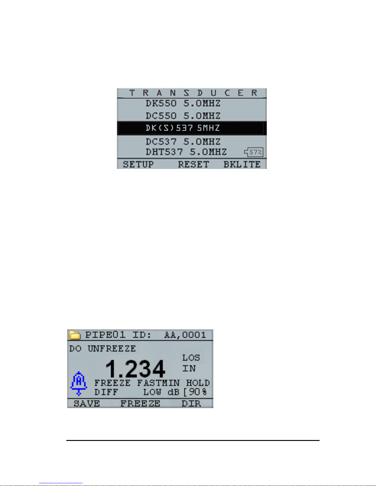
Measurement Mode with a Datalogger
(TKG150)
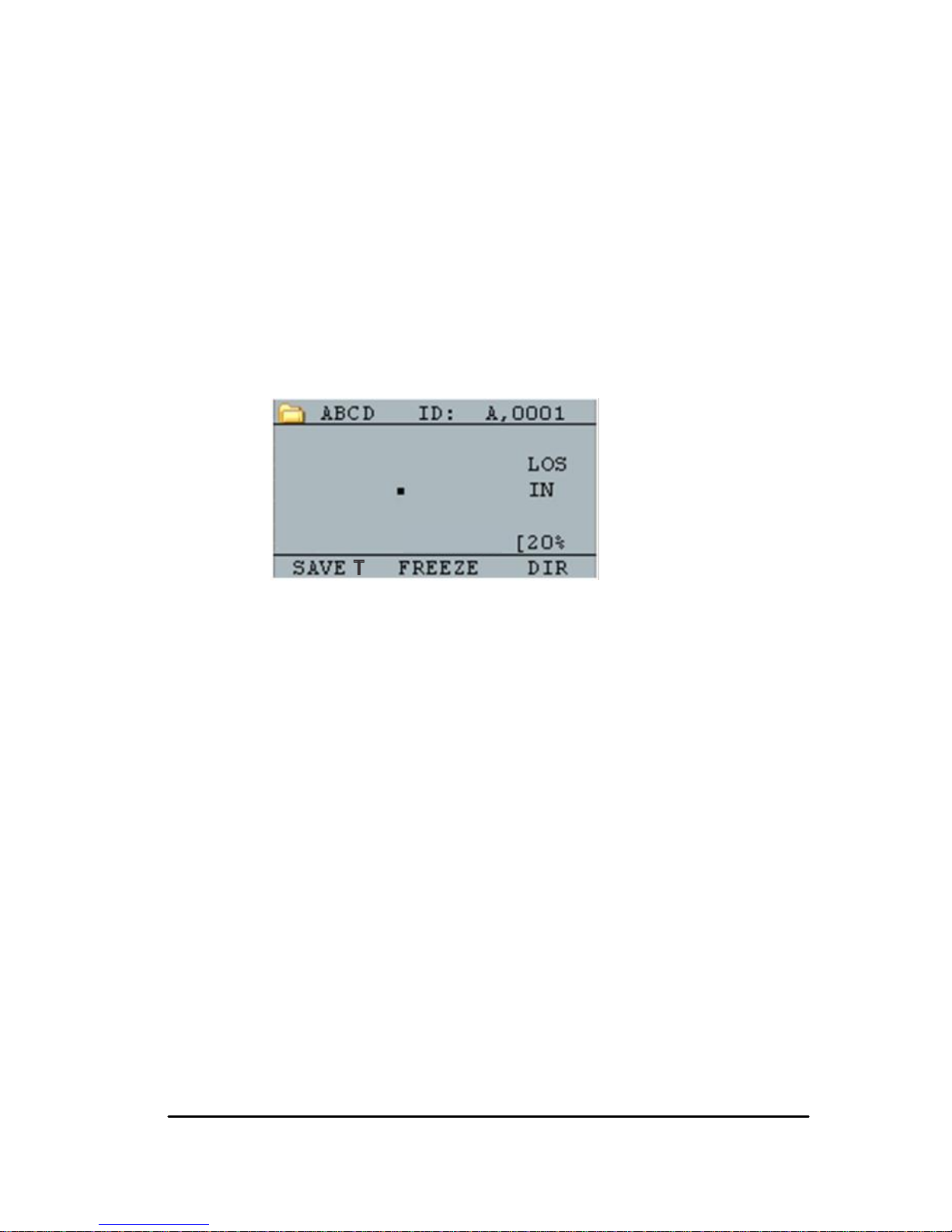
For the TKG150 series datalogger the display screen in
Measurement
mode will look similar to the screen
below:
To continue in
Measurement
mode, follow these steps:
1. Press the F1 key to select the Save T option.
(See: Save section.)
2. Press the F2 key to select the Freeze option.
(See: Freeze section.)
3. Press the F3 key to select the Dir (Directory)
option. (See: Directory section.)
4. Press the Menu / OK key to select the Menu
option. (See: Menu section.)
Page 27

27
Measurement Mode without a Datalogger
(TKG100)
The TKG100 display screen in
Measurement
mode will
look like the screen below:
To continue in
Measurement
mode, follow these steps:
1. Press the F1 key to select the Alarm option.
(See: Alarm section.)
2. Press the F2 key to select the Freeze option.
(See: Freeze section.)
3. Press the F3 key to control the display
backlight. (See: Display Backlight)
4. Press the Menu / OK key to select the Menu
option. (See: Menu section.)
Note: The available choices for F1, F2, F3 are
different for the TKG100 series thickness gauge.
Page 28

Extech Instruments .
28 TKG100_TKG150 Ultrasonic Thickness Gauge User Guide v2.8 11/13 28
Also, the file symbol, filename, ID: xx,xxxx are not
displayed in the TKG100 series thickness gauge.
Page 29

29
Measurement Mode Setup Options
The following modes are available (please note that in the
TKG100 model the Datalogger mode is not available):
To select the Measurements setup mode, first access
the main MENU (using the MENU/OK button from
the Home screen), and then follow these steps:
1. Use the arrow buttons to highlight
MEASUREMENTS and then press Menu OK.
A screen similar to the one below will appear (a
full list of setup options is shown later in this
section):
2. Use the up and down arrow keys to select any
of the setup parameters available and press the
OK key to change the setting. You can also
change the setting using the “Quick Access
Page 30

Extech Instruments .
30 TKG100_TKG150 Ultrasonic Thickness Gauge User Guide v2.8 11/13 30
mode”. To do this, simply use the left and right
key (indicated in the top right hand of the
display screen) to change the setting of the
highlighted parameter.
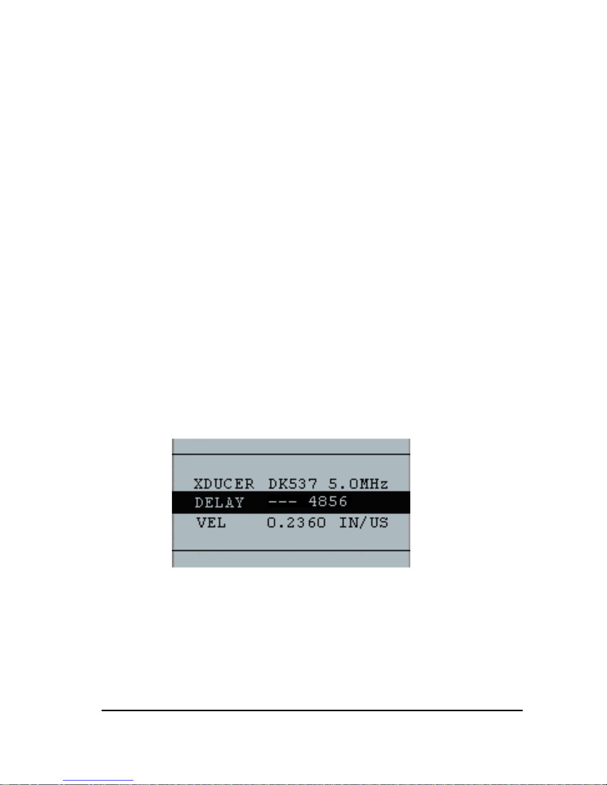
3. The entire list of available MEAUREMENT
MODE parameters for the TKG100 and
TKG150 (red items TKG150 only) are as
follows:
FAST OFF
GAIN LOW dB
HOLD OFF
MEAS, TYPE THICKNESS
VEL 0.23596 IN/US
XDUCER DKS537 5.0MHz
ALARM OFF
BSCAN OFF
DIFF OFF
E-TO-E OFF
Page 31

31
Setting the Clock
The TKG series thickness gauges have an internal realtime clock that includes the year, month, day and time.
This option appears under the Initial Settings option.
The entire list of available clock setup options are as
follows:
TIME FORMAT 12 HR
DATE FORMAT MM/DD
MINUTE 21
HOUR 01 PM
DAY 01
MONTH 01
YEAR 2013
To set the time and date, follow these steps:
1. Select CLOCK from the INITIAL SETTINGS
list in the main MENU.
The following is an example of what the clock
setup screen might look like depending on the
Page 32

Extech Instruments .
32 TKG100_TKG150 Ultrasonic Thickness Gauge User Guide v2.8 11/13 32
previous setup.
2. To change the Time Format, select TIME
FORMAT using up/down arrow keys. Use the
left/right arrow keys to select between 12 HR
and 24 HR options.
3. To change the Date Format, select DATE
FORMAT using up/down arrow keys. Use the
left/right arrow keys to select between
MM/DD and DD/MM options.
4. To set Minute, select the MINUTE option
using up/down arrow keys. Use left/right arrow
keys to decrease/increase the minute value.
You can set the minute value from 00 to 59.
5. To set the Hour, select the HOUR option
using up/down arrow keys. Use left/right arrow
keys to decrease/increase the hour value. If
time is set in 12 HR format, the available hour
values are from 00 AM to 11 PM. If time is set
in 24 HR format, the available hour values are
00 to 23.
Page 33

33
6. To set Day, select the DAY option using
up/down arrow keys. Use left/right arrow keys
to decrease/increase the day value. You can set
the day value from 01 to 31.
7. To set Month, select the MONTH option
using up/down arrow keys. Use left/right arrow
keys to select a Month from JAN to DEC.
8. To set Year, select the YEAR option using the
up/down arrow keys. Use left/right arrow keys
to select the year value from 2005 to 2025.
Press Menu to store the changes and to return to the
INITIAL SETTINGS screen. The real-time clock will
automatically update the date and time once the clock
parameters are selected and stored.
Setting LCD Contrast
To change the display contrast, select Contrast from the
Display option under the main MENU. Use left and right
arrow keys to a select contrast value from 1-64. Press
BACK to save the selection and return to the previous
screen.
Understanding a LOS Reading
LOS (Loss of Signal) occurs when the gauge is not
making a valid reading. This can happen for a variety of
reasons, including the ones in the list below:
Page 34

Extech Instruments .
34 TKG100_TKG150 Ultrasonic Thickness Gauge User Guide v2.8 11/13 34
Not enough couplant
Surface is too rough or rusty
Low Transducer sensitivity
Temperature is too high
Dis-bond exists between the coating and the
steel
In the event you try to save a reading in LOS with the
TKG150, the Notes screen will automatically appear so
that a reason is given for saving an LOS. You can scroll
to the appropriate note and press the soft Save key.
Using the Hold Option
If a LOS occurs, the gauge can continue to display the
last measured thickness by “holding” or freezing the
measurement.
Page 35

35
Using the Fast Option
The Fast option is available by accessing the main
MENU, selecting MEASUREMENTS, and then
selecting FAST from the list.
To select the Fast option, follow these steps:
1. Use the up and down arrow keys to highlight
the Fast option and press the OK key.
2. The following parameters are available:
3. Use the up and down arrow keys to select the
desired parameter and press the OK key.
4. Press F1 Back key to return to the
Measurement mode.
Page 36

Extech Instruments .
36 TKG100_TKG150 Ultrasonic Thickness Gauge User Guide v2.8 11/13 36
In the Measurement the selected Fast option setting is
displayed similar to the screen below:
Helpful Hint: When using the FASTMIN mode, if you
press the F2 key “Freeze” prior to LOS, the gauge will
display the last minimum prior to the LOS so that the
actual couplant on the end of the transducer is not
registered as a legitimate minimum reading.
The parameters that you select in the Fast option are
shown as follows in Measure mode:
FAST when On is selected
FASTMIN when Min is selected
FASTMAX when Max is selected
<BLANK> when Off is selected
The Fast option allows you to select fast updates of
measurements at 20 Hz compared to 4 Hz. If you select
the FastMax option, the LOS will display the LAST
MAX measured value, or if you select the FastMin
parameter the LOS will display the LAST MIN measured
Page 37

37
value. If you select the On parameter from the Fast
option, the LOS will work normally and not show the
measured reading.
The screens below reflect different parameters selected
from the Fast option. For example, the top screen shows
the FASTMAX with LAST MAX measurement on LOS,
and the bottom screen shows the FASTMIN with LAST
MIN measurement on LOS.
Note: The LOS flag indicates the LAST MAX or the
LAST MIN value and is shown based on the FastMax or
FastMin setting.
Page 38

Extech Instruments .
38 TKG100_TKG150 Ultrasonic Thickness Gauge User Guide v2.8 11/13 38
To reset the tracking of LAST MAX and LAST MIN
measured value press the OK (Menu) key.
Using the Gain Option (TKG150 only)
Gain refers to an increase in signal power (echo height)
and is typically measured in decibels (dBs). The Gain
function is useful for setting a reference level where by
making it easier to add or subtract gain. There are three
Gain options, which include: LOW dB, STD dB & HI
dB. The Gain selection is available from the
Measurements mode screen in the Main MENU.
1. Use the up and down arrow keys in the
Measurements screen to highlight the Gain
option.
The following Gain parameters are available:
STD (standard), LO, and HIGH
2. Use the left/right arrow keys to select the
desired Gain option.
3. Press the F1 key to accept the parameter and
return to Measure mode.
Page 39

39
In the Measure mode screen the Gain option that you
select is displayed on the center/right side of the display.
Using the Diff Option
There are 3 Diff options:
ABSOLUTE: Absolute, where the gauge will
display a thickness value as an absolute number.
For example, diff abs = 0.500” and the real
thickness is 1.000 inch, the display will show
diff abs 0.500. If the real value is 0.300, the
gauge will display, -0.200”
PERCENT: When this mode is on, the
displayed value will be listed as a percentage of
the value entered into as the diff. For Example,
if the operator set the diff to percentage at
0.500”, a reading of 0.250” will result in 50%
OFF: Diff Option off.
In the Measure mode screen, highlight the DIFF option
and select the desired option using the right/left arrow
keys. Press F1 to exit Measurement mode and save
settings.
Page 40

Extech Instruments .
40 TKG100_TKG150 Ultrasonic Thickness Gauge User Guide v2.8 11/13 40
5 Alarm Options
Using the Alarm Option
The TKG series thickness gauges offers various alarm
settings to alert you of low or high thresholds via audible
sounds, display flashes, vibrations (if on) and illuminating
keypad. There are several alarms options, which include:
Alarm On/Off: Sets the audible alarm either on
or off.
Low Alarm: Audible alarm will occur and
display will flash when the displayed reading is
less than the low alarm reference value.
High Alarm: Audible alarm will occur when the
displayed reading is higher than the high alarm
reference value.
High_Low Alarm: Audible alarm will occur and
display will flash when the displayed reading is
less than the low alarm or greater than the High
alarm reference value.
Low Alarm/Vibra (TKG150 only): Vibration
alarm will occur and display will flash when the
displayed reading is less than the low alarm
reference value.
High Alarm/Vibra (TKG150 only): Vibration
alarm will occur and display will flash when the
Page 41

41
displayed reading is higher than the high alarm
reference value.
High_Low Alarm/Vibra (TKG150 only):
Audible alarm will occur and display will flash
as well as vibrate when the displayed reading is
less than the low alarm or greater than the High
alarm reference value.
The Alarm option is available from the Measurements
screen list.
1. Use the up and down arrow keys to highlight
the Alarm option and press the OK key (or you
can use Quick Access mode by using the right
or left keys once Alarm is highlighted). For the
TKG100 model you can also press the F1
(Alarm) key to go directly to the Alarm option
without having to go through the Main
MENU/Measurement Mode list.
The ALARM selections available are listed on
Page 42

Extech Instruments .
42 TKG100_TKG150 Ultrasonic Thickness Gauge User Guide v2.8 11/13 42
the previous page.
2. Use the up and down arrow keys to select the
desired alarm type and then press the OK key.
The following screen below appears (screens
will differ slightly based on alarm type
selection). Use the up and down arrow keys to
select the high, low, or percent parameters and
then use the left/right arrow keys to change the
Alarm limits. Press the OK key to continue.
Note: The Low Alarm limit will not go beyond the High
Alarm limit.
3. When you are finished adjusting the setting,
press the F1 key to return to Measure mode.
Page 43

43
Visual and Audible Alarm
The Visual Alarm conditions can be viewed from either a
red, yellow or green LED that light up under the F1, F2,
or F3 keys on the keypad.
As an example, when using the 5 step English test block
with thicknesses of 0.100, 0.200, 0.300, 0.400 and 0.500
inches, if you enter alarm high-low you will first need to
enter the high value. Enter 0.500 and press enter. Next
you will need to enter the low value of 0.100 in. The
display will ask you to enter the percent reading of the
high low. The gauge will default to 20% (this can be
changed with the up or down keys), so any reading within
20% of the high value (approaching high, between 0.400
and 0.499 as 0.400 is within the 20% range of 0.500.) will
result in the yellow keypad lighting up. Also, any reading
above the low value of 0.101 and 0.120 will result in the
yellow F2 keypad lighting up as you are approaching the
minimum
So, in Alarm mode, choosing a non-zero percent value
provides the user with warning for readings approaching
the selected percent value of the high or low limits. For
example, if the alarm value is 0.100" and 20% is entered
as the “percent value”, reading from 0.101" to 0.120" will
result in the F2 “yellow” key being illuminated. Also,
reading less than 0.100" will result in the F1 key “Red”
being illuminated and greater than 0.120" will result in
the F3 “Green” key being illuminated.
Page 44

Extech Instruments .
44 TKG100_TKG150 Ultrasonic Thickness Gauge User Guide v2.8 11/13 44
The Audible Alarm turns the beeper on the gauge either
on or off based on the same alarm conditions used for
visual alarm stated above.
‘Vibra’ Alarm (TKG150 only)
The gauge will physically vibrate when the Vibrating
Alarm is active based on the same alarm condition used
for visual alarm. The Vibrating Alarm, noted as ( ( . ) )
on the gauge display, can be enabled with varying alarms
and alarm conditions as shown on the screens below:
Visual and Audible Alarm is enabled.
The letter A (Alarm) appears in the alarm icon
Page 45

45
Visual, Audible, and Vibrating alarm enabled
.)) symbol appears next to the alarm icon. The letter H
(High) appears in the alarm icon
Alarm condition has occurred meaning the
measured reading is greater than the High
Alarm limit. The letter H (High) appears in the
alarm icon. The screen above has the Vibrating
alarm enabled as the .)) symbol appears next to
the alarm icon.
Page 46

Extech Instruments .
46 TKG100_TKG150 Ultrasonic Thickness Gauge User Guide v2.8 11/13 46
Visual, Audible, and Vibrating alarm enabled
.)) symbol appears next to the alarm icon. The letter L
(Low) appears in the alarm icon
Alarm condition has occurred meaning the
measurement reading is less than the Low
Alarm limit. The letter L (Low) appears in the
alarm icon. The screen above has the Vibrating
alarm enabled as the .)) symbol appears next to
the alarm icon.
Note: For the TKG100, the F1, F2, and F3 choices are
different and the file symbol or the filename along with
ID# are not shown.
Page 47

47
6 Using the Echo-to-Echo Option (TKG150
only)
The Echo-to-Echo option allows you to make
measurements between two consecutive back-wall
echoes. Therefore, a good usage of the Echo-to-Echo
option is for measuring through coatings to measure only
the true metal thickness. There are two Echo-to-Echo
options you can select, which are as follows:
Echo-to-Echo On: Enables the Echo-to-Echo
function
Echo-to-Echo Off: Disables the Echo-to-Echo
function
In the Measurements mode screen in the Main menu,
highlight the E-TO-E option and select the desired
option using the right/left arrow keys. Press F1 to exit
Measurement mode and save settings and F1 again to get
back to the measurement mode.
Page 48

Extech Instruments .
48 TKG100_TKG150 Ultrasonic Thickness Gauge User Guide v2.8 11/13 48
7 Special Gauge Functions
The TKG series thickness gauges have many special
functions that go beyond the basics, mainly in the
TKG150 model. This section will discuss these special
gauge functions in detail.
Using the Save Option (TKG150 only)
You are able to save your data via the Save option.
To use the Save option, follow these steps:
1. From the Measurement mode screen, press
[F1] (Save T).
The data saved will depend on your setup
parameters. For example, if the Notes option is
set to Off (Main MENU, DATALOGGER,
NOTES) the saved thickness readings will be
stored at the ID location [Linear], [Row], [Col]
without notes. (See: Directory selection for file
type details.)
Page 49

49
2. If the Notes option is set to Always then the
thickness reading is stored at the ID location
[Linear], [Row], [Col] with notes. To change the
Notes settings, select the Notes option from the
Datalogger screen in the MAIN Menu.
Now when you press Save T (T for Thickness)
to store a reading in measurement mode, the
following Notes options will be presented:
No comments, not sand blasted, pitting, too hot, broken
insulation, couldn’t read scaffold, needs painting,
broken/missed plug, obstruction, port, burner,
metalized, overlay, already cut out, and pad weld
3. Use the up and down arrow keys to select a
note for the reading and press the OK key. The
selected note will be stored at the ID location,
and based on the file type, [Linear], [Row], or
[Col] is incremented. (See: Directory selection
for file type details.)
Page 50

Extech Instruments .
50 TKG100_TKG150 Ultrasonic Thickness Gauge User Guide v2.8 11/13 50
Using the Freeze Option
You can freeze your data via the Freeze option.
To use the Freeze option, follow these steps:
1. From the Measurement mode screen, press
[F2] (Freeze).
The following screen comes up after pressing
[F2] (Freeze) whereby showing the flag
“Freeze” under the thickness reading. You are
now in Freeze mode. The [F2] selection also
changes from Freeze to Unfreeze.
Page 51

51
TKG150 Datalogger version
TKG100 Non-datalogger version
2. Press [F1] (Save) to save the reading. (See
Using the Save Option for more information.)
3. Press [F2] (Unfreeze) to disable the Freeze
mode
4. Press [F3] (Dir) to perform file operations.
(See Using the Directory Option for more
information.)
5. While in Freeze mode the menu options are
disabled. The display will prompt you to
unfreeze the gauge.
Page 52

Extech Instruments .
52 TKG100_TKG150 Ultrasonic Thickness Gauge User Guide v2.8 11/13 52
TKG150 Datalogger version
TKG100 Non-datalogger version
Page 53

53
Using the Menu Option
For the TKG100 and TKG150 models you can operate
in Measure mode.
To use the Measure mode, follow these steps:
1. Press the Menu (OK) key to select the Menu
options from Measure mode.
Measure mode of the TKG150 Datalogger version
Measure mode of the TKG100 Non-Datalogger version
Page 54

Extech Instruments .
54 TKG100_TKG150 Ultrasonic Thickness Gauge User Guide v2.8 11/13 54
The following Menu options are available:
TKG150 Datalogger version
TKG100 Non-datalogger version
Page 55

55
8 Using Datalogger Directory Mode
(TKG150 only)
Note: This section applies only to the TKG150
Thickness Gauge with a datalogger. If you do not have
a datalogger, you may skip this section.
To use the datalogger Directory mode, follow these
steps:
1. From the Measurement mode screen press
[F3] (Dir) to select the Directory mode.
By pressing [F3] (Dir) you will be able to
review, create, delete, select, rename and clear
stored thickness and copy.
2. Use the up and down arrow keys to view the list
of files, and select whichever one is relevant.
Page 56

Extech Instruments .
56 TKG100_TKG150 Ultrasonic Thickness Gauge User Guide v2.8 11/13 56
3. Press the OK key to select a file in the directory
view.
4. To create a custom file see Creating Custom Files
section.
5. To review thickness readings, see Reviewing a File
section.
6. To rename custom file, see Renaming a File
section.
7. To clear an entire file, see Clearing a File section.
8. To clear selected readings from a file, see
Reviewing a File section.
Page 57

57
9. To create copy of the existing file structures, see
Copying a File section.
10. To delete a custom file, see Deleting a File
section.
The first three files cannot be deleted or
renamed. These files are factory default
files available for you to start storing
thickness reading or make a quick copy of
the file structure (Linear or Grid [Col,
Row]) in order to start saving data in the
new file. (See File System for more
information.)
Page 58

Extech Instruments .
58 TKG100_TKG150 Ultrasonic Thickness Gauge User Guide v2.8 11/13 58
Managing the Datalogger File System
The TKG150 supports the following two files types:
Linear file
: Consists of ID# from 0001 to
5000. The extended memory option consists of
ID# from 1 to 500000.
Grid file
: Consists of ID# as COLUMN and
ROW. The COLUMN is single or double digit
capital alpha character from A to Z and AA to
ZZ. The ROW is a four digit number based on
the 5000 / COLUMN.
For example, when you create a new GRID file with
END COLUMN = C, then the maximum ROW you can
slew up to is limited to 1666 calculated by the instrument
as follows:
The total storage space per file is 5000 readings.
For Columns ending at C, this means 3 columns
are required and the maximum Row allowed is
limited to 5000 / 3 = 1666.
If you create a new GRID file with END COLUMN =
Z, then the maximum ROW you can slew up to is limited
to 5000/26 = 192.
If you create a new GRID file with END COLUMN =
AF, then the maximum ROW you can slew up to is
limited to 5000/(26 for A to Z + 6 for AA to AF) = 156
the grids are created as shown below:
Page 59

59
A,1 to A,156 then
B,1 to B,156 then
:
Z,1 to Z,156 then
AA,1 to AA,156 then
AB,1 to AB,156 then
:
AF,1 to AF,156
If a new GRID file with END COLUMN = ZZ, then
the maximum ROW you can slew up to is limited to
5000/(26 for A to Z + 26*26 for AA to ZZ) = 7.
A,1 to A,7 then
B,1 to B,7 then
:
Z,1 to Z,7 then
AA,1 to AA,7 then
AB,1 to AB,7 then
:
AZ,1 to AZ,7 then
BA,1 to BA,7 then
BB,1 to BB,7 then
:
:
ZZ,1 to ZZ,7
Page 60

Extech Instruments .
60 TKG100_TKG150 Ultrasonic Thickness Gauge User Guide v2.8 11/13 60
Note that there are two different types of Grid files:
ROWINC and COLINC. The above two examples show
how the ID locations are incremented in ROWINC type
file only. Here the Row value is incremented first, while
updating ID location. Whereas, in a COLINC type file,
Column value is incremented first.
So for a COLINC file with END COLUMN value AF,
the ID locations will increment as follows:
A,1 to AF,1 then
A,2 to AF,2 then
.
.
A,156 to AF,156
A COLINC file with END COLUMN value ZZ will
have ID increments as follows:
A,1 to ZZ,1 then
A,2 to ZZ,2 then
.
A,7 to ZZ,7
Page 61

61
Creating Custom Files
To create a custom file in the datalogger, follow these
steps:
1. Press [F3] (Dir) from the Measurement mode
screen.
The following screen appears:
2. Use the up and down arrow keys to highlight
the next Empty file in the list.
Page 62

Extech Instruments .
62 TKG100_TKG150 Ultrasonic Thickness Gauge User Guide v2.8 11/13 62
3. Press the OK key and select RENAME, the
following screen appears:
4. Use the up, down, left, and right arrow keys to
select the characters of the filename. Press the
OK key to accept the selected characters. If you
make an error, press [F2] (Del) to delete the
last character of the entered filename.
5. Press [F3] (Done) when you are finished
entering the filename. The following screen
appears:
6. Use the left and right arrow keys to select a file
type. See the next two sections for more
information on selecting file type for the
new file.
Page 63

63
Selecting a Custom Linear File
When you select a LINEAR file format you are
prompted to select START and END file points.
With the extended memory, you can store up to 100,000
readings allowing you more total files.
Pressing the F3 (Done) key again will take you to the
Measure mode displaying the new filename in the top
left corner and the next ID location in the top right
corner.
Selecting a Custom Grid File
When you select a grid file type, the display changes as
shown below. You can now select the number of rows
and columns for your new file.
Page 64

Extech Instruments .
64 TKG100_TKG150 Ultrasonic Thickness Gauge User Guide v2.8 11/13 64
Use the up and down arrow keys to select the END
ROW option. Now press left or right arrow key to
change the END ROW value. Then press down arrow
key to select END COL option. Press left or right arrow
key to change the END COL value. Since the file size is
limited to 5000, the END COL value is limited to
5000/END ROW. Note that the „FILE SIZE‟ will
change depending on the END ROW and END COL
settings.
When you are finished selecting END ROW and END
COL values, press F3 (Done). The display will go back to
Measure mode, showing the new filename and next ID
location in the top row as shown below.
Page 65

65
Reviewing a File
To review a file from the Measurement mode screen in
datalogger version only, follow these steps:
1. Press [F3] (Dir) from the Measurement mode
screen.
The following screen appears:
2. Select the file you would like to review using the
up and down arrow keys and press the OK key.
Based on the type of file you select, a screen will
appear the same or similar to the one shown in
the example below:
Page 66

Extech Instruments .
66 TKG100_TKG150 Ultrasonic Thickness Gauge User Guide v2.8 11/13 66
CLEAR ALL READI NGS
RENAME
DELETE FI LE
COPY
EXI T
REVI EW DETAI LS
ABCD
REVI EW GRI D
The three factory default files have only 3 options: Clear
All Readings, Copy, and Review Details. Custom files
have 5 options: Clear all readings, Copy, Delete file,
Rename, Review details, and Review Grid. Select the
Review option and press the OK key to review the file.
Reviewing a Linear File
The linear file shows the ID# and the stored readings
along with the units. You can browse the readings by
pressing the up or down arrow key. You can also press
F3 (Beg/End) to go to the beginning or end of the file.
To clear a reading from the file, select the reading to be
cleared by pressing up or down arrow key and then press
Page 67

67
F2 (Clear). Note that once a reading is cleared, it cannot
be restored. To store another reading in the file location
that has been emptied by the Clear operation, highlight
that location by pressing up or down arrow key. Then
press OK to go to the measure mode. When you have
the new reading to be stored in the emptied file location,
press F1 (Save). The new reading will be saved in that
location and the display will show the next empty file
location in the top right corner.
Reviewing a Grid File
The grid file shows the ID# as COL, ROW and the
stored reading with the units. Use the F3 function key to
go to the beginning (BEG) or END of a file list.
Renaming a File
To rename a file from the Measurement mode screen in
datalogger version only, follow these steps:
1. Press [F3] (Dir) for the Directory mode.
Page 68

Extech Instruments .
68 TKG100_TKG150 Ultrasonic Thickness Gauge User Guide v2.8 11/13 68
The following screen appears:
2. Use the up and down arrow keys to select the
file you would like to rename and press the OK
key.
Note: The Rename option is not available for the first
three factory default files.
3. Use the up and down arrow keys to select the
Rename option and press the OK key to
rename the file. A screen the same or similar to
the one below appears.
Page 69

69
4. Use the up, down, left, and right arrow keys to
select the characters of the filename. Press the
OK key to accept the selected characters. If you
make an error, press [F2] (Del) to delete the
last character of the entered filename.
5. Press [F3] (Done) when you are finished
entering the filename. The old filename will be
updated with the new filename in the directory
as shown in the example below.
Note: Press [F1] (Exit) to exit the screen without
renaming the file.
Example:
A user erases a file named ABCD by pressing
[F2] (Del) and selects XYZ as the new
filename and presses [F3] (Done) to accept the
entered new filename.
The old filename in the directory is updated
with the new name.
Page 70

Extech Instruments .
70 TKG100_TKG150 Ultrasonic Thickness Gauge User Guide v2.8 11/13 70
Clearing a File
To clear (or delete) a single thickness reading at a time
from a file, see Reviewing a File section. To clear all the
readings from a file, use the clear file option. To do this,
from measurement mode, press [F3] (Dir) for the
Directory mode.
The following screen appears:
1. Use the up and down arrow keys to select the
file you want to clear and press the OK key.
2. Use the up and down arrow keys to select the
Clear All Readings option and press the OK
key to clear all the stored thickness readings in
that file. The meter will prompt for
Page 71

71
YES/NO/EXIT confirmation:
Press [F1] (Exit) to exit without clearing the
thickness readings.
Press [F2] (Yes) to clear the stored thickness
from the entire file.
Press [F3] (No) to exit without clearing the
thickness readings.
If the file is already clear, the unit will show
„NO READINGS TO CLEAR.‟ message.
Copying a File
To copy a file, from the Measurement mode screen in
datalogger version only, follow these steps:
1. Press [F3] (Dir) for the Directory mode.
Page 72

Extech Instruments .
72 TKG100_TKG150 Ultrasonic Thickness Gauge User Guide v2.8 11/13 72
The following screen appears:
2. Use the up and down arrow keys to select a file
and press the OK key. Any file structure
(factory default or custom) can be copied.
Note: When you copy a file only the structure of the
file ID# is copied and not the associated file readings.
3. Use the up and down arrow keys to select the
Copy option and press the OK key. The
following confirmation prompt or a similar
prompt appears with the next Empty file
highlighted as the default choice.
Page 73

73
Press up or down to select an Empty file and
press OK to assign it a new filename. The
following screen appears.
4. Use the up, down, left, right arrow keys to
select the characters of the filename and press
the OK key to accept the selected characters. If
you make an error, press [F2] (Del) to erase
last character before the cursor.
5. Press [F1] (Exit) to exit without copying the
file.
6. Press [F3] (Done) when you are finished
entering the filename. A new file with the
selected name will be added in the directory
with the file structure of the original file.
Page 74

Extech Instruments .
74 TKG100_TKG150 Ultrasonic Thickness Gauge User Guide v2.8 11/13 74
Deleting a File
To delete a file, from the Measurement mode screen in
the datalogger version only, follow these steps:
1. Press [F3] (Dir) for the Directory mode.
The following screen appears:
2. Use the up and down arrow keys to select the
file to be deleted and press the OK key.
Note: Only custom files can be deleted. The factory
default files cannot be deleted.
3. Use the up and down arrow keys to select the
Delete File option and press the OK key. A
Page 75

75
confirmation prompt for YES/NO/EXIT
appears.
Press [F1] (Exit) to exit the screen without
deleting the file.
Press [F3] (No) to exit the screen without
deleting the file.
Press [F2] (Yes) to delete the file and remove
the file from the directory.
Page 76

Extech Instruments .
76 TKG100_TKG150 Ultrasonic Thickness Gauge User Guide v2.8 11/13 76
7 Technical Specifications
Specifications for the TKG100/TKG150 Ultrasonic
Thickness Gauges
Size: 5" (127 mm) (L) x 3" (76.2 mm) (W) x 1.25" (31.75 mm) (H)
Weight: 8 OZ (.23 kg)
Thickness range: 0.008 - 20 inches (0.20 mm - 508 mm), depending on
material, temperature and transducer selection
Material velocity calibration range: 0.200-0.7362 in/μS (0.508-18.699
mm/μS)
Temperature: Gauge Operating: -4° F to 122° F (-20° C to 50° C) Surface
temperature of material: Depending on probe used, from -5° F to 1000°
F (-20° C to 537° C)
Battery life: Up to 200 hours (40 hours with backlight on)
Battery type: 2 "AA" Alkaline
Display: 128 X 64 Graphics LCD monochrome
Information displays: LOS, min, max, large reading while displaying min
at the same time, velocity, zero, calibration, units, freeze, unfreeze, %
battery life remaining, gain - low, std, high, echo-to-echo symbol
(option)
Resolution: 0.001" (0.01 mm), 0.01" (0.1mm)
Accuracy: Basic Accuracy is 0.004” but on clean smooth steel an
accuracy of 0.001” is not uncommon. The more corrosive the
environment, and pitted the surface under test, the closer to the 0.004”
accuracy one can expect to be. As noted, a higher accuracy can be
obtained when measuring on cleaner steel.
Probe recognition: Via pick list from a menu
Delay line zero measurement: Auto at power up with listed numeric
value. Ideal for correcting delay line wear/curvature and for transducer
acoustic drift at elevated temperatures
Package: Custom, splash-proof, high-impact plastic with rubber,
illuminating keypad for go/no-go testing
Bandwidth: 0.5-20 MHz (-3dB)
Units: English/Metric/Microseconds
Gain: Low, Standard and High for varying test conditions
Measurement rate: 4/sec and 20/sec in fast mode
Page 77

77
Differential Mode: Displays the difference from the actual thickness
measurement and a user entered reference value
Alarms: Minimum/Maximum depth, vibralarm, audible/visual
indications as well as keypad illumination
Illuminating keypad: F1 = Red, F2 = Yellow and F3 = Green for easy,
go/no-go testing (Patent Pending)
Automatic probe wear indicator ( Transducer attendant): Automatically
informs the operator to replace the transducer (Patent Pending)
Ergonomics: User selectable left-handed or right-handed display
changes via keypad (Patent Pending)
Backlight: Light Emitting Diode, On/Off or Auto ON based on valid
readings or last key-press
Shut off: Auto, time out (after X minutes user programmable after no
reading, loss of signal LOS, or no key press)
Scan mode: Displays minimum or maximum thickness value at 20
measurements per second (ideal for high temperature thickness reading
and tracking the minimum depth alarm). Press Freeze to capture last
valid minimum thickness readings prior to Loss of Signal (LOS), without
reading the couplant upon lifting probe off the test piece
Carrying case: Custom molded pouch with wrist strap for either lefthanded or right-handed operators (optional)
Shipping case: Hard plastic with high-density molded cut out for all
accessories (optional)
Freeze mode: Freezes display
Hold mode: Holds display to retain last thickness reading in reverse
video display
Standard TKG includes: Ultrasonic thickness gauge, DK-537 potted, 5
MHz 0.375 inch diameter, operational manual, cable, couplant
Warranty: Limited 2 year warranty
Page 78

Extech Instruments .
78 TKG100_TKG150 Ultrasonic Thickness Gauge User Guide v2.8 11/13 78
Specification differences for TKG100 and TKG150 Models
Item
Specification
150
100
Thickness range
0.008-0.20 inches (20mm-508mm)
x
x
Delay line zero measurement
Auto at power up with listed numeric value.
Ideal for correcting delay line
x
x
Scan mode
Displays minimum or maximum thickness
value at 20 measurements per second
x
x
Hold mode
Holds display to retain last thickness reading
with reverse video display
x
x
Freeze mode
Freezes display
x
x
Units
Inches/Millimeters/Microseconds
x
x
Gain
Low, Standard, or High for varying test
conditions
x
o
Differential mode
Reference value
x
o
Alarms
Illumination and vibration
x
o
Illuminating keypad
F1=Red; F2=Yellow; F3=Green for easy,
go/no-go testing (Patent Pending)
x
o
Auto probe wear indicator
Automatically informs operator to replace
transducer (Patent Pending)
x
o
Echo-to-Echo
Measures the thickness only (ignores paint
and coatings)
x
o
Non-encoded B-scan
Displays cross section of test piece
x
o
Datalogger version
Upgrade to datalogger version
x
o
Carrying pouch
Custom molded with belt clip and elastic
strap
x
o
Note: All software options are field upgradable, no need to return the unit to the factory
Page 79

79
8 Software Options
Echo-to-Echo (TKG150 only)
The Echo-to-Echo feature should and can be used within
the thickness range of the chart listed below. To calibrate
in Echo-to-Echo, first press MENU OK, scroll to set up,
press MENU OK and find where E to E is displayed.
Use the right arrow to turn ON or press MENU OK and
scroll to ON. You will see a symbol in the top right
looking like Echo-to-Echo. Next, press MENU OK, turn
on calibration and perform CAL VEL on the thick part
with the coating and CAL ZERO on the think part with
coating, then MENU OK (note that a thickness block
is required for this operation)
Page 80

Extech Instruments .
80 TKG100_TKG150 Ultrasonic Thickness Gauge User Guide v2.8 11/13 80
B-Scan (TKG150 only)
The B-Scan represents a cross sectional view on the test
piece. The simplest example is to show a 5 step test
block. To turn on the B-Scan on the TKG150, press
MENU/OK, scroll to MEASUREMENTS and press
OK, select B-scan and press MENU/OK. First enter the
maximum thickness you expect to scan using the up,
down, left and right keys, then turn on the B-Scan
scrolling down and right arrow (left arrow for off). Press
F3 in lefty or F1 in righty mode when done. The bottom
of the display will read SAVE, START or STOP and
CLEAR. To Start a B-Scan, couple to a test block and
press F2 [START]. If you uncouple the transducer, BScan will stop due to LOS. If you press F2 [STOP] the
minimum thickness will be displayed in the center of the
screen while a vertical cursor allows you to review
readings. During review the thickness value is updated in
the top right of the display. To save all the readings, press
F1 [SAVE]. The amount of saved readings up to the file
size of 5,000 readings or what was pre-determined in the
current file (See Datalogging) set up. Here is a picture of
the B-Scan on a test block.
Page 81

81
Support Lines: U.S. (877) 439-8324; International: +1 (603) 324-7800
Technical Support: Option 3; E-mail: support@extech.com
Repair & Returns: Option 4; E-mail: repair@extech.com
Product specifications are subject to change without notice
Please visit our website for the most up-to-date information
www.extech.com
FLIR Commercial Systems, Inc., 9 Townsend West, Nashua, NH 03063
ISO 9001 Certified
9 Technical Assistance
Call Extech Instruments for specific technical assistance
or troubleshooting questions. See the customer care
information on the following pages or visit the website
www.Extech.com
Calibration, Repair, and Customer Care
Services
FLIR Systems, Inc. offers repair and calibration services for the
Extech Instruments products we sell. NIST certification for most
products is also provided. Call the Customer Service Department for
information on calibration services available for this product. Annual
calibrations should be performed to verify meter performance and
accuracy. Technical support and general customer service is also
provided, refer to the contact information provided below.
Copyright © 2013 FLIR Systems, Inc.
All rights reserved including the right of reproduction in whole or in part in any form
www.extech.com
Page 82

Extech Instruments .
82 TKG100_TKG150 Ultrasonic Thickness Gauge User Guide v2.8 11/13 82
Lignes d’assistance: États-Unis (877) 439-8324
International: +1 (603) 324-7800
Service d‟assistance technique : Option 3 ; E-mail : support@extech.com
Réparations et retours : Option 4 ; E-mail : repair@extech.com
Les spécifications produit sont sujettes à modifications sans préavis.
Pour les toutes dernières informations, veuillez visiter notre site Web.
www.extech.com
FLIR Commercial Systems, Inc., 9 Townsend West, Nashua, NH 03063 USA
Certifié ISO 9001
Calibrage, réparation et services après-vente
FLIR Systems, Inc. offre des services de calibrage et de
réparation pour les produits Extech Instruments que nous
commercialisons. Nous fournissons également une certification NIST
pour la plupart des produits. Contactez notre service client pour toute
information sur les services de calibrage disponibles pour ce produit.
Un calibrage doit être effectué chaque année pour vérifier les
performances et la précision du mètre. Nous offrons également une
assistance technique et un service à la clientèle. Veuillez vous reporter
aux coordonnées fournies ci-dessous.
Copyright © 2013 FLIR Systems, Inc.
Tous droits réservés, y compris la reproduction partielle ou totale sous quelque forme que ce
soit.
www.extech.com
Page 83

83
Servicios de calibración, reparación y atención
a clientes
FLIR Systems, Inc., ofrece servicios de reparación y calibración
para los productos que vendemos de Extech Instruments. Además
ofrecemos certificación NIST para la mayoría de los productos. Llame
al Departamento de Servicio al Cliente para solicitar información de
calibración para este producto. Para verificar el funcionamiento y
precisión se debe realizar la calibración anual. Además se provee
Soporte Técnico y servicios generales al cliente, consulte la información
de contacto en seguida.
Líneas de soporte: EE.UU. (877) 439-8324; Internacional: +1 (603) 324-7800
Soporte Técnico Opción 3; correo electrónico: support@extech.com
Reparación / Devoluciones: Opción 4; correo electrónico: repair@extech.com
Las especificaciones del producto están sujetas a cambios sin aviso
Por favor visite nuestra página en Internet para la información más
actualizada
www.extech.com
FLIR Commercial Systems, Inc., 9 Townsend West, Nashua, NH 03063 USA
Certificado ISO 9001
Copyright © 2013 FLIR Systems, Inc.
Reservados todos los derechos, incluyendo el derecho de reproducción total o parcial en cualquier medio
www.extech.com
Page 84

Extech Instruments .
84 TKG100_TKG150 Ultrasonic Thickness Gauge User Guide v2.8 11/13 84
 Loading...