

Page 1
User's Guide
R/C SMD Tweezers Multimeter
Model RC200
Page 2
RC200-EU-EN-V1.4-3/11 2
Introduction
Congratulations on your purchase of the Extech RC200 RC Tweezers Multimeter This meter,
using the tweezers adaptor, measures SMD capacitors, resistors, diodes and continuity test.
With the test lead adaptor, it measures AC/DC Voltage. Proper use and care of this meter will
provide many years of reliable service.
Safety
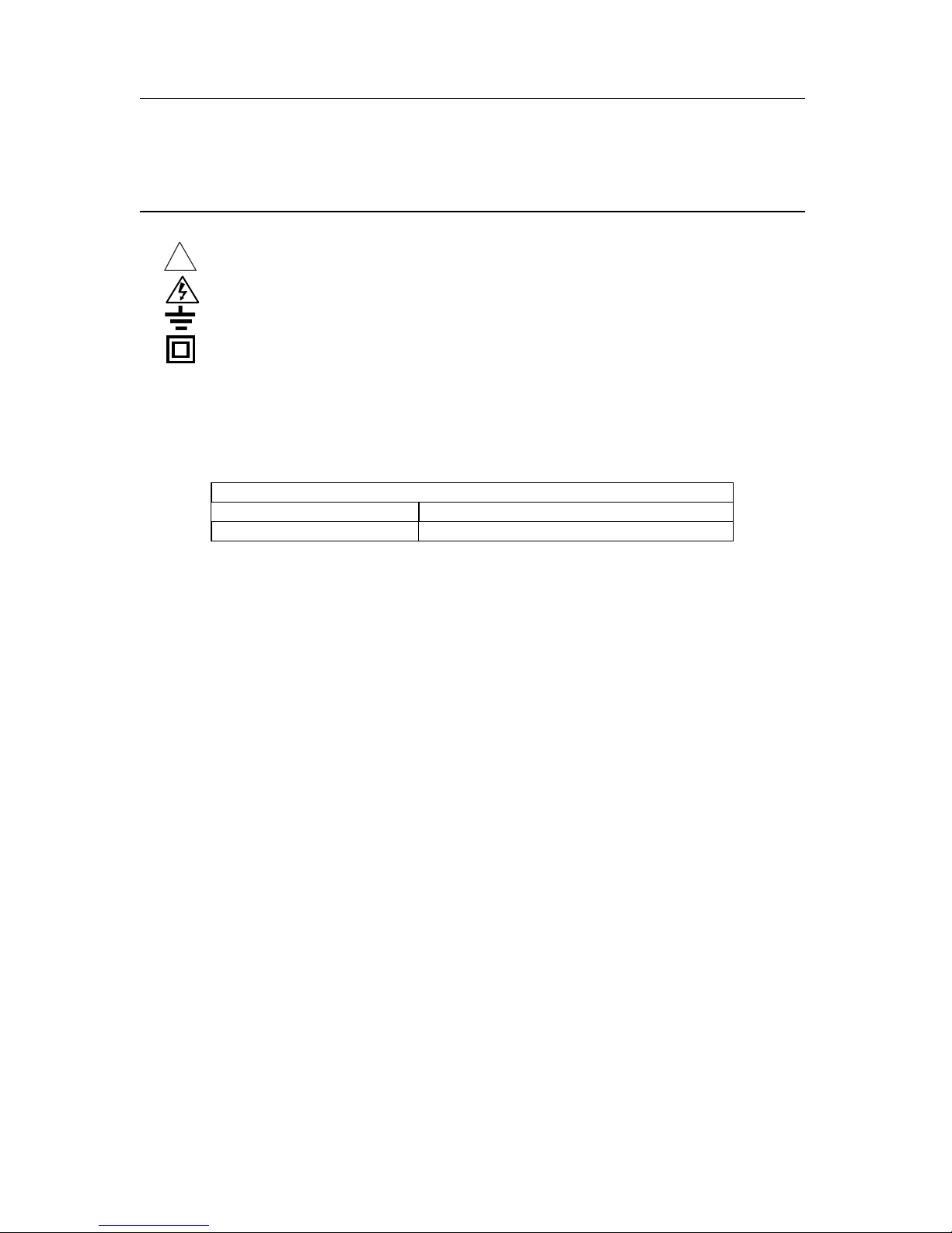
INTERNATIONAL ELECTRICAL SYMBOLS
Caution ! Refer to the explanation in this Manual
Caution ! Risk of electric shock
Earth (Ground)
Double Insulation or Reinforced insulation
This meter has been designed for safe use, but must be operated with caution. The rules
listed below must be carefully followed for safe operation.
1. NEVER measure voltage with the Tweezer adaptor installed.
2. NEVER apply voltage or current to the meter that exceeds the specified maximum:
Input Protection Limits
Function Maximum Input
V DC or V AC 600V DC/AC
3. USE EXTREME CAUTION when working with voltages greater than 25VAC or 35VDC.
These voltages are considered a shock hazard.
4. DO NOT measure voltage if the voltage on the "COM" input jack exceeds 600V above
earth ground.
5. NEVER connect the meter leads across a voltage source while the function switch is in
the capacitance, resistance, or diode mode. Doing so can damage the meter.
6. ALWAYS discharge filter capacitors in power supplies and disconnect the power when
making capacitance, resistance, continuity or diode tests.
7. ALWAYS turn off the power and disconnect the test leads from the circuit before
opening the cover to replace the batteries.
8. NEVER operate the meter unless the battery cover is in place and fastened securely.
9. NEVER operate the meter if any part is damaged.
10. ALWAYS turn the meter off when not in use.
!
Page 3

RC200-EU-EN-V1.4-3/11 3
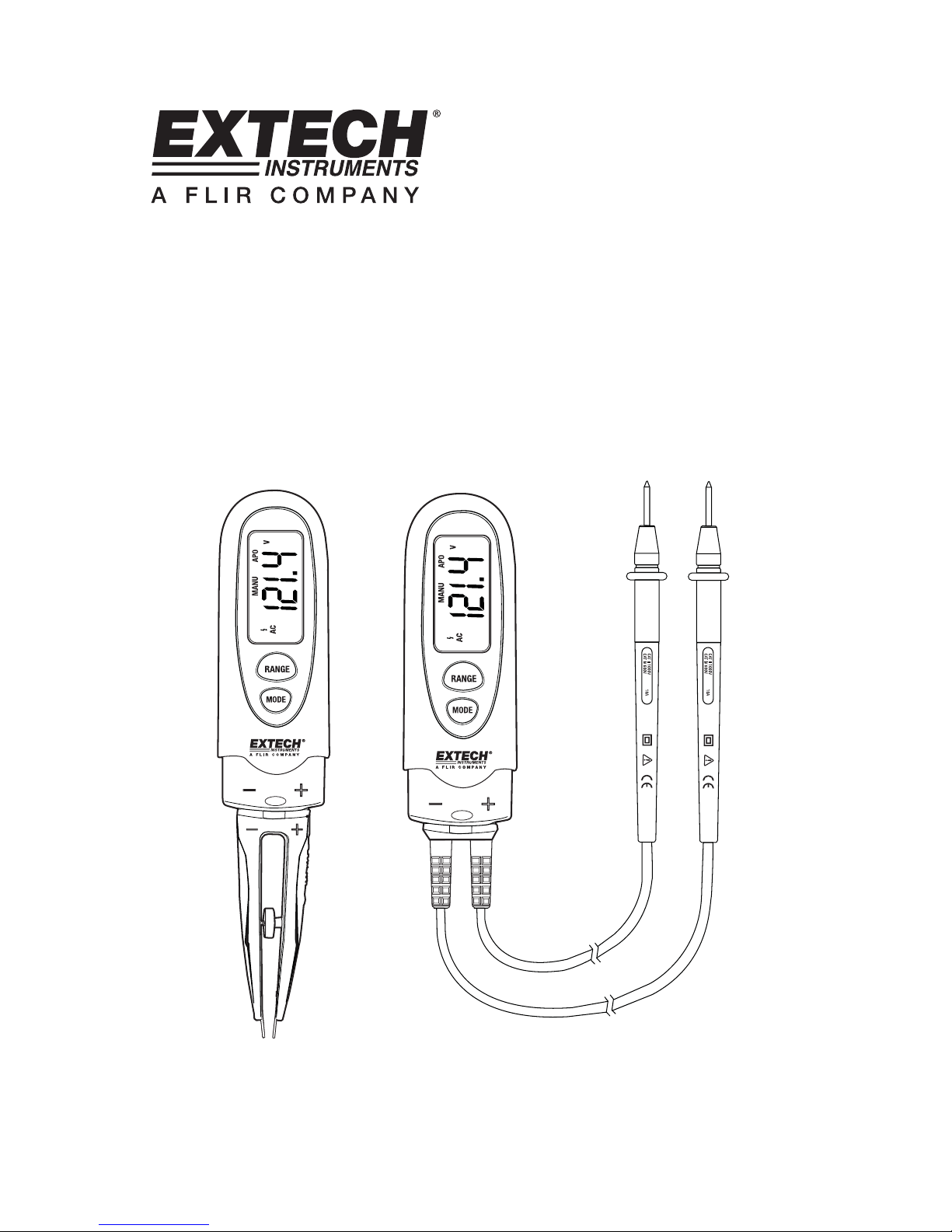
Description
1. LCD display
2. RANGE button
3. MODE and Power button
4. Spacing adjustment
5. Tweezer contacts
6. Voltage adaptor
7. Batter compartment (rear)
LCD Display Symbols
Low battery
Continuity
Diode
>30V caution icon.
n nano (10
-9
) (capacitance)
µ micro (10
-6
) (amps, cap)
m milli (10
-3
) (volts, amps)
k kilo (10
3
) (ohms)
F Farads (capacitance)
M mega (10
6
) (ohms)
Ω Ohms
V Volts
AC AC voltage
DC DC voltage
AUTO Auto Range
SCAN SCAN mode
APO Auto power off enabled
1
2
3
4
5
6
7
Page 4

RC200-EU-EN-V1.4-3/11 4
Operating Instructions
WARNING: Risk of electrocution. High-voltage circuits, both AC and DC, are very
dangerous and should be measured with great care.
1. If “OL” appears in the display during a measurement, the value exc eeds the range you
have selected. Change to a higher range.
2. The meter will automatically recognize if the voltage test leads or tweezers adaptor is
inserted.
3. The meter will turn on with autoranging “AUTO” selected. In this mode, the unit will
automatically select the proper range to measure the device under test. Press the
“RANGE” button to go to manual (“MANU”) ranging. Continue pressing the button until
the range desired is selected. Press and hold the RANGE button for two seconds to
return to autoranging.
4. On some low AC and DC voltage ranges, with the test leads not connected to a device,
the display may show a random, changing reading. This is normal and is caused by the
high-input sensitivity. The reading will stabilize and give a proper measurement when
connected to a load.
Test Lead AC/DC Voltage Measurements
1. Insert the voltage adaptor into the meter observing the polarity indicators.
2. Press the MODE button for 2 seconds until the meter beeps. “V” will be displayed on the
LCD
3. Press the MODE button to select either AC or DC voltage.
4. Touch the black test probe tip to the negative side of the circuit.
Touch the red test probe tip to the positive side of the circuit.
5. Read the voltage in the display.
Note: The “
“ DANGER symbol will appear in the display whenever the measured voltage
exceeds 30V
WARNING: To avoid electric shock, disconnect power to the unit under test and
discharge all capacitors before taking any capacitance or resistance measurements.
Remove the batteries and unplug line cords.
Tweezer Resistance, Capacitance, Continuity and Diode Measurements.
1. Insert the tweezers adaptor into the meter observing the polarity indicators.
2. Press the MODE button for 2 seconds until the meter beeps. The meter turns on in the
SCAN mode and “- - - -“ on the display.
3. Insert a component into the tweezers contacts. In the SCAN mode, the meter
automatically selects the proper range and units (Capacitance or Resistance).
4. Read the measurement results in the display.
5. Press the MODE button to exit the SCAN mode and begin resistance measurements.
The “Ω” icon will appear on the display.
6. Press the MODE button for continuity measurements. The
icon will appear on the
display. The meter will beep if the resistance is less than the continuity threshold.
7. Press the MODE button for diode measurements. The
icon will appear on the
display. A good diode will read “OL” in one direction and a low voltage in the opposite
direction.
8. Press the MODE button for capacitance measurements .The “F” icon will appear on the
display. It can take several minutes for the reading to stabilize at the final value for large
value capacitors.
9. Press the MODE button again to return to the SCAN mode.
Page 5

RC200-EU-EN-V1.4-3/11 5
Power OFF and Auto Power OFF
Press and hold the MODE button for 4 seconds to manually turn power off. The auto off
feature will automatically turn the meter off after approximately 10 minutes of inactivity..
Low Battery Indication
The
icon will appear in the display when the battery voltage becomes low. Replace the
battery when this appears.
Maintenance
1. KEEP THE METER DRY. If it gets wet, wipe it off.
2. USE AND STORE THE METER IN NORMAL TEMPERATURES. Temperature
extremes can shorten the life of the electronic parts and distort or melt plastic parts.
3. HANDLE THE METER GENTLY AND CAREFULLY. Dropping it can damage the
electronic parts or the case.
4. KEEP THE METER CLEAN. Wipe the case occasionally with a damp cloth. DO NOT
use chemicals, cleaning solvents, or detergents.
5. USE ONLY FRESH BATTERIES OF THE RECOMMENDED SIZE AND TYPE. Remove
old or weak batteries so they do not leak and damage the unit.
6. IF THE METER IS TO BE STORED FOR A LONG PERIOD OF TIME, the batteries
should be removed to prevent damage to the unit.
BATTERY INSTALLATION
1. Turn power off.
2. Open the rear battery cover by removing the two Phillips head screws located on the
rear of the meter.
3. Insert the batteries into battery holder, observing the correct polarity.
4. Put the battery cover back in place. Secure with the screws.
5.
You, as the end user, are legally bound (Battery ordinance) to return all used
batteries and accumulators; disposal in the household garbage is prohibited!
You can hand over your used batteries / accumulators at collection points in your
community or wherever batteries / accumulators are sold!
Disposal: Follow the valid legal stipulations in respect of the disposal of the device
at the end of its lifecycle
NOTE: If your meter does not work properly, check the batteries to make sure that the y are
still good and that they are properly inserted.
Page 6

Specifications
ycaruccA noituloseR egnaR noitcnuF
600mV 0.1mV
6V 0.001V
60V 0.01V
±(0.8% reading + 2 digits)
DC Voltage
600V 0.1V
±(1.0% reading + 4 digits)
600mV 0.1mV
6V 0.001V
±(1.0% reading + 4 digits)
60V 0.01V
AC Voltage
50 to 60Hz
600V 0.1V
±(1.2% reading + 6 digits)
600Ω 0.1Ω
6kΩ 0.001kΩ
60kΩ 0.01kΩ
600kΩ 0.1kΩ
±(1.5% reading + 8 digits)
6MΩ 0.001MΩ
Resistance
60MΩ 0.01MΩ
±(2.5% reading + 8digits)
6nF 0.001nF
±(5.0% reading + 50 digits)
60nF 0.01nF
±(5.0% reading + 7 digits)
600nF 0.1nF
6μF 0.001μF
60μF 0.01μF
600μF 0.1μF
±(3.0% reading + 5 digits)
6mF 0.001mF
apacitance
60mF 0.01mF
±(10% reading + 10 digits)
NOTE: Accuracy is stated at 18oC to 28oC (65oF to 83oF) and less than 75% RH.
Diode Test Test current 1mA, open circuit voltage 3V DC typical
Continuity Check Audible threshold 10 to 40 ohms.
Input Impedance 10MΩ (VDC & VAC)
AC Response Average responding
ACV Bandwidth 50Hz to 60Hz
Display 6000 count liquid crystal
Overrange indication “OL” is displayed
Polarity Automatic (no indication for positive); Minus (-) sign for negative
Auto Power Off 10 minutes (approx)
Low Battery Indication “
” is displayed if battery voltage drops below the operating
voltage
Batteries Two button batteries, AG13/LR44 or equivalent
Battery life Approximately 60 hours
Operating Temperature -10ºC to 50ºC (14ºF to 122ºF)
Storage Temperature -30
o
C to 60oC (-4oF to 140oF)
Operating Humidity Max 80% up to 31ºC (87ºF) decreasing linearly to 50% at 40ºC
(104ºF)
Storage Humidity <80%
Operating Altitude 2000 meters (7000ft) maximum.
Weight 65g (2.3oz)
Size 181 x 35 x 20mm (7.1 x 1.4 x 0.8”)
Safety For origin of installation use and in accordance with the
requirements for double insulation per EN61010-1 and IEC610101 2
nd
Edition (2001) to Overvoltage Category III 600V; Pollution
Degree 2.
Copyright © 2011 Extech Instruments Corporation (a FLIR company)
All rights reserved including the right of reproduction in whole or in part in any form.
more infor for Extech RC200
Phone: 01235 838 555
Email: cs@airconcern.co.uk
Web. www.airconcern.co.uk
Air Concern Ltd, Building 173 Curie Avenue Harvell Didcot, Oxfordshire
 Loading...