

Page 1

EXTECH DATA SYSTEMS
MSP/MPP II/III
COMPACT PORTABLE PRINTER
USER'S MANUAL
VERSION: 2.0
DATE: August 1995
Extech Data Systems
(A Division of Extech Instruments Corporation)
335 Bear Hill Road
Waltham MA 02154
Part Number: 7A060023
Page 2

About this Manual
Objective
This User's Manual supplies the necessary information for installing and operating Extech
MPP/MSP compact portable printer series.
Contents
Chapter 1:
This chapter starts with the visual overview of your MSP/MPP printer series. Power, data,
ribbon, paper and installation procedures are covered and supported with helpful diagrams. At
the end of this chapter you are ready for the initial power-up and printer self-test.
Chapter 2:
This chapter starts with the operational overview of your MSP/MPP printer series. The features
of each module comprising the printer are described. The printer operating modes are detailed.
The character set, fonts, controls, characters and graphics print commands are listed.
Chapter 3:
In this chapter RS232C and 8 Bit Parallel Centronics interface input pins, operation and
electrical characteristics are listed. The Serial Baud Rate and Parity selection and 8 bit parallel
operation are described.
Appendix A:
Serial MSP/MPP Users guide.
Appendix B:
MSP/MPP printer trouble shooting guide.
Appendix C:
Magnetic Card Reader Option
Appendix D:
Infrared Data Input Option
Page 3
Page 3

NOTE:
FCC Part 15 Class B
This equipment has been tested and found to comply with the limits for a Class B digital device,
pursuant to Part 15 of the FCC rules. These limits are designed to provide reasonable
protection against harmful interference in a residential installation. This equipment generates,
uses and can radiate radio frequency energy and, if not installed and used in accordance with
the instructions, may cause harmful interference to radio communications. However, there is no
guarantee that interference will not occur in a particular installation. I F THIS EQUIPMENT
DOES CAUSE HARMFUL INTERFERENCE TO RADIO OR TELEVISION RECEPTION, which
can be determined by turning the equipment off and on, the user is encouraged to try too correct
the interference by one or more of the following measures:
-R eorient or relocate the receiving antenna.
-Increase the separation between the equipment and the receiver.
-Connect the equipment into an outlet on a circuit different from that to which the
receiver is connected.
-Consult the dealer or an experienced radio/TV technician for help.
Warranty
This printer is warranted by Extech Data Systems to be free of defects in parts and
workmanship for a period of one year from date of shipment. (The customer is responsible for
ensuring proper packing to prevent damage in transit.) This warranty does not apply to defects
resulting from action of the user such as misuse, improper wiring, operation outside of
specification, improper maintenance or repair, or unauthorized modification. Extech specifically
disclaims any implied warranties of merchantibility or fitness for a specific purpose and will not
be liable for any direct, indirect, special, incidental or consequential damages. Extech's total
liability is limited to the repair or replacement of the product. The warranty set forth above is
inclusive and no other warranty, whether written or oral is expressed or implied.
Warranty Service (Call 617 890 7440)
A Return Authorization number must be issued before a unit is returned to Extech for repair.
Once a unit has been properly returnd to Extech, it will be repaired (estimates are provided first
if the repair cost is estimated above $50.00) and returned via UPS ground. The customer may
elect a faster mode of transport at their cost.
Page 4
Page 4

Contents
1.0 INSTALLATION AND INITIAL POWER-UP
1.1 MODEL NUMBER
1.2 UNPACKING YOUR PRINTER
1.3 FRONT PANEL LED INDICATORS
1.4 MEMBRANE SWITCH PANEL
1.5 DATA CONNECTOR
1.6 POWER INPUT
1.6.1 AC POWER ADAPTER
1.6.2 DC POWER CONNECTION (OPTIONAL)
1.6.3 INSTALLING BATTERY
1.7 INSTALLING PAPER AND RIBBON
1.7.2 INSTALLING PAPER
1.7.2 INSTALLING RIBBON
1.8 INITIAL POWER-UP AND SELF-TEST
2.0 OPERATING YOUR COMPACT PRINTER PART I
2.2 PRINTER MECHANISM
2.2.1 PRINTER PAPER SPECIFICATION
2.3 PRINTER POWER
2.3.1 MANUAL POWER-UP AND POWER-DOWN
2.3.2 AUTO POWER DOWN TIMER
2.3.4 PRINTER BATTERY PACK
2.4 CONTROL CHARACTERS
2.5 BUILT-IN CHARACTER FONTS
2.6 CHARACTER SIZE
2.6.1 NORMAL CHARACTER
2.6.2 EXPANDED CHARACTER
2.6.3 EXTENDED CHARACTER
2.6.4 LARGE CHARACTER
2.6.5 PRINTER CHARACTER SET
2.7 DOT ADDRESSABLE GRAPHICS
2.7.1 GRAPHIC CHARACTER SET
2.7.2 GRAPHICS CHARACTER HEX DOT PATTERNS
2.8 OPERATING PRINTER IN MS-DOS ENVIRONMENT
2.9 OPERATING PRINTER IN WINDOWS ENVIRONMENT
2.1 PRINTER CONTROLLER
2.3.3 POWER-UP VIA DATA INTERFACE
Page 5
Page 5

3.0 OPERATING YOUR COMPACT PRINTER PART II
3.1 MSP - RS232C SERIAL INTERFACE
3.1.1 MSP SERIES - SERIAL COMMUNICATION PROTOCOL
3.1.2 MSP SERIES - SERIAL BUSY PROTOCOL
3.1.3 MSP SERIES - XON/XOFF PROTOCOL
3.1.4 MSP SERIES - RS232C CONNECTIONS
3.1.5 MSP SERIES - OPTIONAL RJ11 - RS232C CONNECTOR
3.1.6 MSP SERIES - RS232C TECHNICAL SPECIFICATIONS
3.2 MPP SERIES - 8 BIT PARALLEL INTERFACE
3.2.1 MPP SERIES - PARALLEL INTERFACE OPERATION
3.2.2 MPP SERIES - PARALLEL INTERFACE SPECIFICATIONS
3.2.3 MPP SERIES - PARALLEL INTERFACE TIMING DIAGRAMS
3.2.4 MSP/MPP SERIES - DATA CONNECTOR
Appendix A Serial MSP/MPP Users guide.
Appendix B
Appendix C
Appendix D
MSP/MPP printer trouble shooting guide.
Magnetic Card Reader Option
Infrared Data Input Option
Page 6
Page 6

Chapter 1 Installation and Initial Power-Up
1.0 INSTALLATION AND INITIAL POWER-UP
Thank you for selecting the Extech compact portable printer. The MPP/MSP printer series
feature compact reliable, plain paper dot matrix printers capable of printing 24 through 42
columns and dot addressable graphics. Packaged in rugged Cycolac enclosure, it is designed
for use as a table top or portable battery operated printer.
These printers are available in two types of interfaces, either serial RS232C or 8 bit parallel. All
models feature 2048 character print buffer to free the host computer during the printing process.
The serial RS232C printers (models MSP II or MSP III) support all standard serial
communication handshakes, the communication rate and the protocol are set via dip switches.
The 8 bit parallel printers (models MPP II or MPP III) support Centronics compatible
communication handshakes.
1.1 MODEL NUMBER
To best meet OEM requirements, the Extech compact portable printers are manufactured in a
variety of configurations. The Model number of your printer is shown on the front panel label
(Figure 1.0).
The model number of the printer is comprised of three fields. The first field specifies the type of
communication interface installed, the second field specifies print speed and the third field
specifies the number of the print columns. The model number convention summarizing the
features of the printer are listed below.
MSP - II - 24
(1) (2) (3)
(1) Printer interface type:
MSP . . . . . . Serial RS232C interface
MPP . . . . . . 8 bit parallel interface
(2) Print speed:
II . . . . . . 40 Characters per second (CPS)
III . . . . . . 60 Characters per second (CPS)
(3) Print columns:
For II . . . . 24 or 42 columns
For III . . . . 24 or 40 columns
The instructions in this manual apply to the following Extech compact printers.
MODEL # DESCRIPTION PART #
MSP-II -24 Mini Serial Printer 40CPS - 24 columns 76716F0
MSP-II -42 Mini Serial Printer 40CPS - 42 columns 76718F0
MPP-II -24 Mini Parallel Printer 40CPS - 24 columns 76916F0
MPP-II -42 Mini Parallel Printer 40CPS - 42 columns 76918F0
MSP-III-24 Mini Serial Printer 60CPS - 24 columns 76816F0
MSP-III-40 Mini Serial Printer 60CPS - 40 columns 76818F0
MPP-III-24 Mini Parallel Printer 60CPS - 24 columns 77016F0
MPP-III-40 Mini Parallel Printer 60CPS - 40 columns 77018F0
Page 7
Page 7

Chapter 1 Installation and Initial Power-Up
1.2 UNPACKING YOUR PRINTER
When you remove the printer from its shipping box, make sure it is in good condition. The
package also includes an AC power adapter, rechargeable battery pack, paper roll, a warranty
registration card. If any of the components are missing, contact Extech or your distributor for
assistance.
Keep the packing material so you can repack the printer for storage or shipment. If there is any
visible damage to the printer, record it on the freight bill, have the freight carrier acknowledge it
and submit your claim to the carrier.
Caution: Do not install or operate damaged equipment as safety and performance may be
affected.
1.3 FRONT PANEL LED INDICATORS
Five LED lights are used for various printer function indications. These LEDs are located on the
front panel of the MSP/MPP Printer series. The functions assigned to these lights are as
follows:
ON-Line indicator
The green LED, labeled <ON-Line>, illuminates if the printer is selected.
Low BAT indicator
The Yellow LED, labeled <Low BAT>, illuminates if the battery pack is depleted. Recharge
battery pack if LED is on.
Charge indicator
The Yellow LED, labeled <Charge>, illuminates if battery is accepting charge. It turns off
automatically at the end of the charge cycle.
Ready indicator
The green LED, labeled <Ready> is used for the following:
-The <Ready> LED illuminates if the printer senses the presence of the AC power.
-The <Ready> LED illuminates if a command to enable Magnetic card reader is
received.
Error indicator
The red LED, labeled <Error>, is used for the following indication:
- The <Error> LED flashing:
The <Error> LED flashes at a rate of once per second for 5 seconds, before
auto-shutoff of the printer.
- The <Error> LED stays lit:
The <Error> LED stays lit if the printer control card fails to turn on the printer
mechanism, due to low battery or paper jam or if an error is detected while
reading the magnetic card.
Page 8
Page 8

Chapter 1 Installation and Initial Power-Up
1.4 MEMBRANE SWITCH PANEL
Four membrane switches are provided on the left side of the MSP/MPP printers for various
operator controls. The switches are labeled <SLCT>, <FEED>, <SET> and <ADVN>. The
functions performed by these switches are summarized below.
<SLCT> or <ON>
The <SLCT> or <ON> switch is used to turn printer power on.
The green <ON-Line> LED is illuminated, if printer is selected.
<FEED>
The <FEED> switch is used to advance the paper by one line.
<SET> or <OFF>
The <SET> or <OFF> switch is used to turn the printer OFF. The <Error> LED starts flashing
when set switch is pressed.
<ADVN> 0r < >
The <ADVN> or < > switch is used to advance paper by one line.
1.5 DATA CONNECTOR
The Data Connector of the MSP/MPP printer is located at the front of the printer. Figure 1.0
shows the front panel of the MSP/MPP Printer series. The serial and parallel input/output
signals of the MSP/MPP compact printers are terminated on a 25 pin, DB25S female connector.
Pin assignments and technical specifications for each type of interface are listed in Chapter 3.
1.6 POWER INPUT
The MSP/MPP compact printers receive DC power via Extech rechargeable battery pack or
through a two (2) conductor Power Input Connector located on the right side of the printer.
NOTE: The printer must be operated with the battery installed when the
Power Adapter is used. Failure to do so will invalidate the warranty.
1.6.1 AC POWER ADAPTER
A wall mount UL listed power adapter is provided to operate the printer. The AC Power
Adapter plugs directly into an AC power outlet while it's mating DC plug, on a 6 ft
extension, connects to the printer. The center pin is the positive DC input, while the
body of the connector is logic common or DC negative input.
The AC Power Adapter is internally fused and it's output is rated at 9 VDC/1.0A for
MSP II printer series and 9VDC/2.0A for MSP III. The Power adapter AC input is
available for either 110 VAC or 220 VAC.
Page 9
Page 9
Chapter 1 Installation and Initial Power-Up
PART # DESCRIPTION
152117 MSP/MPP II 110 VAC IN / 9VDC 1A Out
152220 MSP/MPP II 220 VAC IN / 9VDC 1A Out
153117 MSP/MPP III 110 VAC IN / 9VDC 2A Out
153220 MSP/MPP III 220 VAC IN / 9VDC 2A Out
151129 DC CAR ADAPTER
1.6.2 DC POWER CONNECTION (OPTIONAL)
For DC powered units, a two conductor power plug is provided. Refer to Table 1.0 to
connect power to your DC unit. No internal fuse is provided with DC units. It is strongly
recommended to install external fuses with the values shown in the table 1.0.
Table 1.0 below summarizes Voltage, Current and Fuse requirements for AC and DC
configurations.
MODEL # VOLTAGE +/- CURRENT FUSE
MSP/MPP 110VAC 10% .1A INTERNALLY FUSED
MSP/MPP 220VAC 10% .06A INTERNALLY FUSED
MSP/MPP 7.5-
13.6VDC
Voltages, Currents and Fuses
1.6.3 INSTALLING BATTERY
Install the battery pack provided into the battery compartment at the bottom of
the printer.
The battery pack provided must be charged over night prior to its first use.
To charge the battery pack use the AC adaptor provided. 8-10 hours are required
to recharge the battery pack.
The MSP/MPP printers are capable of delivering from one to two hours
continuous printing on a full charge.
-- 4 WATTS 1.0A SLB
Table 1.0
1.7 INSTALLING PAPER AND RIBBON
The printer is shipped from the factory with paper and ribbon installed, refer to this section to
install new supply of paper and ribbon. The paper tray and ribbon cartridge of the MSP/MPP
compact printers are located inside the printer enclosure. To access the paper tray and the
ribbon cartridge the back cover must be removed. To remove the back cover, press in at the
arrow mark while pulling the back cover up.
1.7.1 INSTALLING PAPER
Remove the back cover (section 1.7 and figures 1.1 and 1.3).
Turn on the printer by pressing the <SLCT> or <ON> switch.
Page 10
Page 10

Chapter 1 Installation and Initial Power-Up
Tear and discard any paper remaining in the printer tray.
Remove any paper remaining in the printer mechanism, using the <FEED> switch.
Do not REVERSE pull paper out of the printer mechanism - this will damage
the printer mechanism
Feed the new roll of paper into the printer paper slot using the <FEED> switch.
1.7.2 INSTALLING RIBBON
Remove the back cover (section 1.1 and figure 1.3).
Remove the worn ribbon by pressing with one finger at the location labeled
"EJECT" on the ribbon cartridge.
Insert the new ribbon in place and press at the extreme ends of the ribbon
cartridge to secure it in place.
With your thumb, tighten the ribbon by rotating clockwise the ribbed wheel located
on the front of the ribbon cartridge.
Feed paper to insure that the paper passes through exposed ribbon and ribbon
cartridge case.
1.8 INITIAL POWER-UP AND SELF-TEST
A self-test feature is built into your MSP/MPP compact printer series. To start the self-test,
press the <FEED> switch during initial power-up of the printer (see below).
Once the battery is installed and all the front panel LED indicators are turned off (press the
<OFF> or <SET> switch to turn off) press and hold down the <FEED> switch, then press the
<SLCT> or <ON> switch, this will automatically start the self test. The self-test program checks
the integrity of the operating program installed, the 2048 character print buffer, the processor
watchdog, and the power supervision circuits. The printer performs an internal self-test and
prints the self-test findings, current printer settings, and starts continuous print of the built-in
printer character fonts. To stop the self-test process, press the <FEED> switch.
If no problems are found, the following messages are printed:
TEST PRINT DESCRIPTION
2K BUFFER EXTECH V2.2 (C) 1994 This line shows the version of the installed Eprom
and the size of print buffer.
INTERFACE: SERIAL Type of interface selected SERIAL or PARALLEL.
MODE:2400,8,N,1 Baud=2400, number of Data bits=8, Parity= None,
Stop bits = 1
Note:
The red <Error> LED will turned on if any error is encountered during self test.
If any problem is encountered during self test. Refer to APPENDIX C for a brief trouble shooting
guide.
Page 11
Page 11

Chapter 2 Operating Your Compact Printer
2.0 OPERATING YOUR COMPACT PRINTER PART 1
The MSP/MPP compact portable printer series is comprised of a microcomputer-based printer
controller card, a printer mechanism module, a rechargeable battery pack and a high impact
cycolac enclosure.
2.1 PRINTER CONTROLLER
The MSP Serial printers use the Extech Part Number EX075 circuit board while the MPP
Parallel printers use the Extech EX076 circuit board. A powerful INTEL micro-controller on
these highly integrated circuit boards manage's all the features supported by the printer. The
circuit board incorporates the printer drivers, communication interfaces, 2K print buffer, the front
panel switch inputs, battery charger and power regulator circuits.
Upon initial power-up, the Printer Controller goes through extensive self-test procedures. It
verifies the amount of print buffer installed and restores the default printer settings. In the idle
mode, the printer controller continuously checks the front panel controls, the data input
interface, the print buffer, the DC and battery pack voltage levels and processor watchdog
supervisor.
The data sent to the MSP/MPP printer series is received by the controller on an interrupt basis.
The controller validates the data before saving it in the print buffer. The power regulator and
battery charger features are summarized in section 2.3.
2.2 PRINTER MECHANISM
The MSP/MPP compact printers are designed using highly reliable high speed alphanumeric
impact printer mechanisms. The MSP/MPP printer mechanisms require only +5VDC for
operation and are guarded against possible malfunction by a special protection circuit included
on the control card. The printer ratings are as follows.
MSP - II MSP - III
Reliability 1,000,000 character lines 1,500,000 character lines
Print speed 40 Characters per second 60 Characters per second
The MSP/MPP III printer mechanisms are built with eight dot driver coils, while the MSP/MPP II
printers have six dot driver coils. Both type of mechanisms include gears for fast paper feeding.
Using a continuous, pre-inked ribbon cassette (part # 757131 ), they can print 5x7, 10x14, 5x14
or 10X14 dot matrix characters or user defined graphics image.
Below is a detailed specification on printed character size, line spacing and number of total dots
for each mechanism used in MSP/MPP printer series.
Mechanism #
EX180 24 1.7(W) X 2.6(H) mm 2.06 mm 3.78 mm 144
EX183 42 1.1(W) X 2.6(H) mm 1.29 mm 3.78 mm 252
EX190 24 1.7(W) X 2.6(H) mm 2.06 mm 3.78 mm 144
EX192 40 1.2(W) X 2.6(H) mm 1.35 mm 3.78 mm 240
Columns Character-size Column-spacing Line spacing dots/line
Page 12
Page 12

Chapter 2 Operating Your Compact Printer
2.2.1 PRINTER PAPER SPECIFICATION
The MSP/MPP printers use 2.25" wide, .0027" thick and 1.12" diameter rolls of common
calculator paper. Three types of paper may be used in the printer, Single ply roll,
Two ply pressure sensitive roll, Label stock Custom Kiss-cut with perforation. Below is
the specification for each type of the paper.
Single Ply 757058 (5 rolls) 2.25"/57.5 mm .0027" / .08 mm 25' / 6.3 m
Two Ply 757135 (5 rolls) 2.25"/57.5 mm .0035" / .09 mm 16' / 4.0 m
Label stock Custom made 2.25"/57.5 mm label .066 mm custom lengths
Kiss-cut w/perf. carrier .058 mm
PAPER TYPE
PART # WIDTH THICKNESS LENGTH
2.3 PRINTER POWER
Printer power, battery locations and characteristics were described in section 1.6. This section
reviews the printer power and battery operation and specification.
Like any battery-power device, the battery pack supplied with the MSP/MPP printers have finite
life. The maximum usage between recharge will be obtained when the following simple rules are
followed.
- Turn off printer when not in use.
- Recharge until the <charge> LED turns off, indicating full charge.
- Use Extech power adapter to recharge the battery pack.
- Use "Logic Switching" capacity in your software to facilitate
the auto turn on or turn off of the printer.
2.3.1 MANUAL POWER-UP AND POWER-DOWN
The <SLCT> or <ON> membrane switch is used to turn the printer ON manually. The
<ON-Line> LED indicator is turned ON when <SLCT> or <ON> switch is pressed.
Press the <SET> or <OFF> switch to turn off the printer power. The red <Error> LED
starts flashing momentarily, to indicate the start of the power down process. This
process will last about 5 seconds.
2.3.2 AUTO POWER DOWN TIMER
The MSP/MPP printers have a built-in 30 second Power-Down-Timer. The timer is
automatically restarted under any one of the following conditions.
- If any of <SLCT> or <ON>, <FEED> or <ADVN> or <OFF> switches are
pressed.
- If a character is received via data interface.
Upon timeout of the Power-Down-Timer, the printer starts flashing the red <Error> LED
to worn the operator and transmits the power down command string to the host.
The power down timer may be disabled by activating the <RTS> or <SELECT> signals
on the interface connector.
Page 13
Page 13

Chapter 2 Operating Your Compact Printer
2.3.3 POWER-UP VIA DATA INTERFACE
The MSP/MPP printer can be powered-up by transmitting a single character or
activating <RTS> or <SELECT> signals on the interface connector.
To avoid the loss of data during "Logic Switching", the following software features must
be implemented in the Host program.
After sending a wake up character or activating the <RTS> or <SELECT> signals.
- Pause for 1.6 seconds before sending additional characters to the printer.
- Verify the status of <CTS> or <BUSY> before sending additional characters.
- Wait for the XON character from the printer.
The printer turns off power automatically, 30 seconds after the last character received
or de-activation of the <RTS> or <SELECT> signals.
2.3.4 PRINTER BATTERY PACK
The MSP/MPP printer is designed to operate with a 5.0 VDC/ 800 mAH rechargeable
Ni-Cd battery pack. The battery recharge and monitor circuits are located on the printer
controller.
Two LED indicators showing the status of the battery pack are provided.
The <Low BAT> LED is turned on when the battery voltage drops below 4.1
volts.
The <Charge> LED is on while the battery is accepting charge. It turns off
automatically at the end of the charge cycle, when battery voltage reaches 5.56
volts.
8 to 10 hours are required to fully recharge the batteries. Up to 216,000 characters can
be printed with a fully charged battery pack.
The battery pack will hold charge for 800 to 1000 hours after complete recharge.
Remove the battery pack from the printer battery compartment during long storage or
shipping. Additional battery packs and a 4 pack battery charger are available. The part
numbers and descriptions of these accessories are:
PART # CAPACITY DESCRIPTION
7A100002 700 mAH 700 mAH battery pack
7A100003 800 mAh 800 mAh battery pack
767500 Simultaneous 4 battery pack charger
The Extech AC adapters and their respective specification are listed in section 1.6.1 of
this manual.
Page 14
Page 14

Chapter 2 Operating Your Compact Printer
2.4 CONTROL CHARACTERS
The printer has a set of commands which provide control of printer functions. The printer also
provides response commands informing the user of the printer status. In this section, the
recognized control characters and the corresponding printer actions are summarized.
CHAR. CON H/D CONTROL ACTION
EOT
BS
HT
LF
VT
FF
CR
SO
SI
XON
AUXON
XOFF
NORM
^D
04/04
^H
08/08
^I
09/09
^J
0A/10
^K
0B/11
^L
0C/12
^M
0D/13
^N
0E/14
^O
0F/15
^Q
11/17
^R
12/18
^S
13/19
^T 14/20 Return to normal print.
End Of Text
printer sends an EOT character when buffer
is empty. This is used to tell the host
that printer is in idle mode.
Back Space
remove previous character in print buffer.
Horizontal Tab
Tab to 5,9,13,17,21,25,29,33,37 or to the
beginning of next line.
Line Feed
Advance to beginning of next line.
Vertical Tab
Advance 5 lines.
Form Feed
Advance 10 lines.
Carriage Return
Advance to beginning of next line.
clears double width or extended print
pending.
Shift Out
All characters are printed in double width
(10x7)
Shift In
All characters are printed in normal width
(5x7).
Transmitter On
Printer to Host: Ready to receive data.
Host to printer: The host is ready to
accept data.
Print on
Printer to Host: Print is on line.
Transmitted after initial power up or
clearing of printer jam.
Printer receiver is off
Printer to Host: Print Buffer is full.
Host to Printer: Host transmitter off.
Page 15
Page 15

Chapter 2 Operating Your Compact Printer
CHAR. CONT H/D CONTROL ACTION
AUXOFF
CANCEL
ESC
EXTEND
EXTEND
OFF
^U 15/
21
^X
18/
24
1B/
^[
^\
^]
27
1C/
28
1D/
29
Printer to Host: printer is off
transmitted to host before power down
Cancel and reset printer
If received, 2K print buffer is reset
and printer placed in initial power-up
default settings.
Escape
Escape character precedes graphics and
printer operating modes. Refer to escape
command section.
Extended print
All characters following this command
are printed double high (5x14).
Extended print off/Normal print
All characters following this command
are printed normal size (5x7)
2.5 BUILT-IN CHARACTER FONTS
The MSP/MPP printer has three built-in user select fonts. Below is the list of commands to
select these fonts.
FONT TYPE FONT DESCRIPTION COMMAND STRING
Standard ASCII and International character set ESC+F+1
IBM PC ASCII and IBM PC character set ESC+F+2
Hebrew ASCII and IBM PC character set ESC+F+3
The characters are formed using a 5x7 matrix. The first 127 entries in the font tables are ASCII
characters. Characters 0 through 31 are reserved ASCII printer control characters, while 32
through to 127, are the 96 ASCII Alpha numeric upper and lower case characters.
The alternate characters for each font type are from 128 to 255.
The printer defaults to Standard font on initial power-up or upon receiving the CANCEL
character (^X,18H,24).
Page 16
Page 16

Chapter 2 Operating Your Compact Printer
2.6 CHARACTER SIZE
Four character sizes can be selected through the communication interface, by sending control
characters to the printer.
Character Size Dot matrix
size
Normal 5x7
Expanded (Double Wide) 10x7
Extended (Double Height) 5x14
Large (double wide and
double height)
2.6.1 NORMAL CHARACTER
The Normal characters are formed using a 5x7 dot matrix. The printer defaults to 5x7
matrix Normal character size upon initial power-up.
2.6.2 EXPANDED CHARACTER
Expanded size or double wide characters are formed by using 10x7 dot matrix.
Expanded print is selected by sending the EXPAND character command(0E/14) to the
printer, all succeeding characters are printed in Expanded form. Sending the EXPAND
OFF character (0F/15) or Carriage Return resets the Expanded print to normal print.
2.6.3 EXTENDED CHARACTER
The Extended or double height characters are formed by using a 5x14 dot matrix.
Extended Print can be selected through the communication interface by sending the
EXTEND command (1C/28) character. EXTEND (1D/29) or Carriage return resets the
Extended print to normal print.
2.6.4 LARGE CHARACTER
The Large characters are formed by using a 10x14 dot matrix. Large character print is
selected if both Expanded and Extended print is selected. To reset large print to normal
print, Expanded and Extended prints must be disabled or Carriage return sent to
printer.
2.6.5 PRINTER CHARACTER SET
The following Table lists the entire printable character set, starting at ASCII code 32
(space character).
10x14
Page 17
Page 17

Chapter 2 Operating Your Compact Printer
2.7 DOT ADDRESSABLE GRAPHICS
The MSP/MPP Compact Printers can print special symbols, graphs and characters if operated
in the Dot Addressable Graphics mode.
During the Dot Addressable Graphics mode of operation, the printer prints one dot line at a time.
Each horizontal dot line is made out of (1x6) dot cells, and the total number of dot cells per line
is the same as the maximum number of columns on the printer.
For example, a model MSP-II-24 Column has a total of 24 (1x6) dot cells corresponding to its
24 column capacity.
Each dot in a (1x6) dot cell can be turned ON or OFF by sending specific ASCII characters.
The graphics mode is invoked by sending ASCII characters 'ESC' (1B/27) followed by 'G'. Dot
line printing starts upon receiving enough dot cells to complete a dot line, or
ASCII 'CR' (0DH) or ASCII 'LF' (0AH).
The graphics mode is terminated by sending ASCII characters 'ESC', followed by 'A'.
2.7.1 GRAPHIC CHARACTER SET
The graphic character set extends from the character '?'(3FH) to TILDA (7EH). Bits 1
through 6 of the characters received are used to turn ON or OFF the dots in a dot
cell.
If a bit is set (=1), a dot is enabled, otherwise the dot is disabled.
For example for ASCII '?' (3FH or 00111111B), bits 1 through 6 are set. Sending
consecutive '?'s will form a one dot solid line across the paper.
2.7.2 GRAPHICS CHARACTER HEX DOT PATTERNS
The following table, Table 1, outlines the dot patterns and HEX codes for graphics
operation.
Table 1
Dot patterns and HEX codes
Page 18
Page 18

Chapter 2 Operating Your Compact Printer
2.8 OPERATING MSP/MPP PRINTER IN MS-DOS ENVIRONMENT
To insure proper operation of the Extech MPP/MSP printers in DOS environment the following
are required.
FOR MPP SERIES - Parallel Printer
1- Use DOS print command to print, or Write Direct to printer port.
2- Set the printer port for infinite retry using the dos MODE command.
MODE LPT1:,,P
FOR MSP SERIES - Serial Printer
1- Use DOS print command to print, or Write Direct to printer port.
2- Set the PC's communication baud using DOS MODE command, printer
and PC baud rate and parity have to match.
Mode com1:9600,n,8,1,r
3- Redirect PC's serial (COM) port to parallel (LPT)
mode lpt1:=com1:
4- Set the printer port for infinite retry using the dos MODE command.
MODE LPT1:,,P
2.9 OPERATING MSP/MPP PRINTER IN WINDOWS ENVIRONMENT
To insure proper operation of the Extech MSP/MPP in a windows environment the following are
required.
Select Generic/text only printer driver.
Use Windows printer manager.
For MPP Parallel printers, Set the PC's parallel (LPT1) port as follows.
- LTP1: Local Port
- Device not selected: 15
- transmission retry: 45
- Fast printing Direct to Port enabled
For MSP serial printers, Set the PC's serial port (COM1) baud rate and parity to match
printer. Use printer Self-Test to verify baud rate and parity setting.
Page 19
Page 19

Chapter 2 Operating Your Compact Printer
3.0 OPERATING YOUR COMPACT PRINTER PART 2
This chapter describes the input connections, operation, and electrical characteristics for all
MSP/MPP printers.
- The operating features of the MSP Serial printers are covered in section 3.1.
- The operating features of the MPP Parallel printers are covered in section 3.2.
3.1 MSP SERIES: SERIAL COMMUNICATION SPEED AND
PARITY
The proper Baud Rate and protocol settings are required to communicate with a host computer.
The standard factory setting is 9600 BAUD, 8 DATA BITS, NO PARITY BIT, and one STOP
BIT.
A six position dip switch, located to the left of the paper tray, can be used to set the baud rate
and parity (Figure 3.1). The printer reads these switches once on initial power-up.
Switches 1 and 2 are used to set the communication speed/baud rate.
SW1 SW2 BAUD RATE
ON ON 1200
OFF ON 2400
ON OFF 4800
OFF OFF 9600
Switch 3 selects number of data bits.
.
SW3 DATA BITS
OFF 8 DATA BITS
ON 7 DATA BITS
Switches 4 and 5 are used for parity selection
SW4 SW5 PARITY
BIT
OFF OFF No parity
OFF ON No parity
ON OFF Odd parity
ON ON Even parity
The printer self-test can be used to print and verify the current serial settings.
A sample test print is shown in SECTION 1.8.
Page 20
Page 20

3.1.1 MSP SERIES - SERIAL COMMUNICATION PROTOCOL
Two communication protocols are supported by the MSP printer series - SERIAL BUSY
PROTOCOL and XON/XOFF PROTOCOL.
3.1.2 MSP SERIES - SERIAL BUSY PROTOCOL
In this mode, Pins 4 (RTS - From Host ) and 5 (CTS - From Printer) are used to control
data flow to and from the printer. This protocol is available for serial RS232C version
printers.
The <RTS> signal from the Host (pin #4) is used to enable the printer, the printer raises
<CTS> (pin #5) when it is ready to accept data.The printer lowers <CTS> line when
either the Print Buffer has less than 64 unused locations or when TEST OR FEED is
selected. The <RTS> signal is monitored during data transmission from the Printer to
Host. The printer transmits data to Host only if <RTS> is high.
3.1.3 MSP SERIES - XON/XOFF PROTOCOL
The Printer transmits XON when it is ready to accept data, and XOFF for conditions A
and B listed above. Under XON/XOFF protocol, the data flow out of the printer's Serial
Port is halted on receipt of XOFF from Host and resumed on receipt of XON.
3.1.4 MSP SERIES - RS232C CONNECTIONS
The RS232C Interface signals for the MSP printer series are terminated on a DB25S
female connector located at the front of the printer. Six connections are provided from
the Serial Interface to the host computer for proper operation of this option. A minimum
of two connections are required for operation, RXD-pin2 and Common-pin3.
The table below lists the Serial Interface signals and pinouts on the DB25S female
connector.
MSP DB25S CONNECTOR
PIN #
1 Protective Earth
FUNCTIONAL
DESCRIPTION
SIGNAL
NAME
GND
Ground
2 RS232 from Host
RXD
(INPUT)
3 RS232 from Printer
TXD
(OUTPUT)
4 Request to send from
RTS
Host (INPUT)
5 Clear to send from
CTS
Printer (OUTPUT)
7 Logic common COM
Page 21
Page 21

3.1.5 MSP SERIES - OPTIONAL RJ11 - RS232C CONNECTOR
The table below lists the Serial Interface signals and pinouts for the Extech MSP
printer series with RJ11 type space saving data connector.
The six (6) pin RJ11 data connector is located at the left side of the printer adjacent to
power input connector. The pin # 1 is on the left side of the connector.
Five connections are provided from the Serial Interface to the host computer for proper
operation of this option. A minimum of two connections are required for operation,
RXD-pin3 and Common-pin1 or pin5.
MSP RJ11 CONNECTOR
PIN #
FUNCTIONAL
DESCRIPTION
SIGNAL
NAME
1 and 5 Logic common COM
2 RS232 serial output
TXD
From Printer to Host
3 RS232 serial input
RXD
From Host to Printer
4 Clear To Send output
CTS
From Printer to Host
6 Request To Send input
RTS
From Host to Printer
3.1.6 MSP SERIES - RS232C TECHNICAL SPECIFICATIONS
RS232C technical specifications are as follows:
DATA TRANSFER RATE: 1200 Through 9600 Baud
Dip switch select
WORD LENGTH: 1 Start bit
7 Or 8 Data bits
1 Or 2 Stops bits
SIGNAL LEVELS: Mark or Logical 1 = -3 to -15VDC
Space or Logical 0 = +3 to +15VDC
HANDSHAKING: RTS/CTS or XON/XOFF
Page 22
Page 22

3.2 MPP SERIES - 8 BIT PARALLEL INTERFACE
The Parallel Interface signals for the MPP printer series are terminated on a 25 pin IBM PC
parallel printer output type connector located on the front panel of the printer.
The table below lists the Parallel Interface signals and the connector pinouts. A (/) before a
signal name indicates the signal is ACTIVE LOW; otherwise, the signal is ACTIVE HIGH.
___________________________________________________________________________
PIN# SIGNAL NAME DIRECTION FUNCTION
___________________________________________________________________________
1 /STROBE INPUT DATA READY FROM HOST
2 DATA 1 INPUT DATA BIT 1 FROM HOST
3 DATA 2 INPUT DATA BIT 2 FROM HOST
4 DATA 3 INPUT DATA BIT 3 FROM HOST
5 DATA 4 INPUT DATA BIT 4 FROM HOST
6 DATA 5 INPUT DATA BIT 5 FROM HOST
7 DATA 6 INPUT DATA BIT 6 FROM HOST
8 DATA 7 INPUT DATA BIT 7 FROM HOST
9 DATA 8 INPUT DATA BIT 8 FROM HOST
10 /ACK OUTPUT RECEIVE ACKNOWLEDGE FROM PRINTER
11 BUSY OUTPUT BUSY OUTPUT FROM PRINTER
12 COMMON SIGNAL COMMON
13 4.7K PULL UP TO VCC
14 /PAPER-FEED INPUT PAPER FEED REQUEST FROM HOST
15 4.7K PULL UP TO VCC
16 NO CONNECTION
17 SELECT-IN INPUT SELECT PRINTER FROM HOST - OPTIONAL
18 THRU 25 SIGNAL COMMON
___________________________________________________________________________
A minimum of 12 connections are required for the parallel interface operation (pin 1 through 12).
3.2.1 MPP SERIES - PARALLEL INTERFACE OPERATION
Pin #1 of the Parallel Interface connector carries the </STROBE> signal from the host
computer to the printer. This signal is held at TTL HIGH level normally, and lowered by
the computer when the data is ready for the printer. The fact that the signal went low is
latched by the printer control card and the processor is interrupted to read, validate,
and save the data received.
Also, the <BUSY> signal (Pin#11) is set to indicate that the printer is busy reading data
received.
Upon saving the received data, the printer lowers </ACK> (Pin #10) to acknowledge
that the data has been received, and lowers the BUSY signal.
Page 23
Page 23

3.2.2 MPP SERIES - PARALLEL INTERFACE SPECIFICATIONS
DATA TRANSFER RATE: 6000 Characters/second
SYNCHRONIZATION: Via </STROBE> line
HANDSHAKING: </ACK> and <BUSY> Signals
SIGNAL LEVELS: Compatible with CMOS and TTL levels.
3.2.3 MPP SERIES - PARALLEL INTERFACE TIMING DIAGRAMS
3.2.4 MSP/MPP SERIES - DATA CONNECTOR
Page 24
Page 24

Appendix A
Serial MSP/MPP Users guide
This Guide summarizes the operating and maintenance feature of Extech MSP or MPP printer
series. Refer to user's and operators manual for additional information.
Initial preparation
- Install the battery pack in the battery compartment located on the back of the printer.
- Recharge battery pack overnight by using the Extech power adapter provided.
- Connect the Data Connector located on the front of the printer.
- Set the communication parameters (serial printers only).
- If interfacing to PC, set MS-DOS and Windows variables.
Initial power up and self-test
- Press <SLCT> or <ON> switch to turn on printer.
- Press <SET> or <OFF> to turn off printer.
- To start self-test Hold <FEED> switch then press <SLCT> or <ON>.
Install Paper
- Remove the back cover
- Turn on the printer by pressing the <SLCT> or <ON> switch.
- Tear and discard any paper remaining in the printer tray.
- Remove any paper remaining in the printer mechanism, using the <FEED> switch.
Do not REVERSE pull paper out of the printer mechanism - this will damage printer.
- Feed the new roll of paper into the printer paper slot, press the <FEED> switch to advance the
paper.
Install Ribbon
- Remove the back cover
- Remove the worn out ribbon by pressing with one finger at the location labeled "EJECT" on
the ribbon cartridge.
- Insert the new ribbon in place and press at the extreme ends of the ribbon cartridge to secure
it in place.
- With your thumb, tighten the ribbon by rotating clockwise the ribbed wheel located on the front
of the ribbon cartridge.
- Feed paper to insure the that paper passes through exposed ribbon and ribbon cartridge case.
Page 25
Page 25

Membrane Switch Functions
<SLCT> or <ON>
The <SLCT> switch is used to turn printer power on. The green <ON-Line> LED is turned on, if
printer is selected.
<FEED>
The <FEED> switch is used to advance the paper by one line.
<SET> or <OFF>
The <SET> switch is used to turn the printer OFF. The red <Error> LED starts flashing when
<SET> switch is pressed.
<ADVN> or < >
The <ADVN> switch is used to advance paper by one line.
Front Panel Indicators
<ON-Line> Green - If illuminated the printer is selected.
<Low BAT> Yellow - If illuminated the battery pack is depleted. Recharge battery pack if
LED is on.
<Charge> Yellow - If illuminated the battery is accepting charge.
Turns off automatically at the end of the charge cycle.
<Ready> Green - illuminated if the printer senses the presence of the AC power.
Green - illuminated if a command to Enable Magnetic card reader is
received.
<Error> Red - Flashing indicates start of power down process.
Red - illuminated steady if the battery is
too low to turn on the printer mechanism.
Red - illuminated steady Magnetic card
reading Error.
Page 26
Page 26

Appendix B
Trouble Shooting Guide
PROBLEM POSSIBLE CAUSE SOLUTION
Printer will not turn on Discharged Battery Recharge battery overnight.
Charge LED not lighting No AC power Check AC outlet and adapter.
when AC adapter is
plugged in Bad AC Adapter Battery pack fully charged.
Battery not Charging Battery incorrectly Check Battery installation
installed or no AC. and AC adapter.
Poor print Quality Worn ribbon Replace ribbon.
Paper not feeding Obstruction in paper Check the paper path.
path or improperly Verify installation.
installed. Use paper with the right thickness
Error LED on Steady Print Mechanism Jam Press <FEED> to clear problem.
Low Battery If problem persists recharge
battery or cycle power.
Low-BAT LED on Steady Low AC or Battery. Recharge Battery
Prints illegible characters Improper Baud rate Verify the printer and Host setting.
and parity. Match, use test print to verify
Printer setting.
In MS-DOS use write direct to port
In WINDOWS use Generic printer
driver, print manger and direct
write to port.
Printer will not print Improper cabling. For MSP verify that PC's pins 6,8
and 20 tied together.
For MPP make proper cable is in
use, all 25 pins connected
straight through.
Page 27
Page 27

APPENDIX C
Magnetic Card Reader Option
Introduction
An optional Magnetic Card Reader is available for the MSP/MPP series printers. This option is
designed to read Magnetic Cards conforming to ISO standards (ABA, IATA, MINTS and
THRIFT), convert the encoded signals to ASCII format and transmit the information to the host
computer or terminal.
Three Types of Magnetic Card Reader Heads are available. The part number, Model number
and functional description of each type are summarized in Table 1. The Model number of the
Magnetic Card Reader installed in the printer is shown on a label located inside the printer
battery compartment.
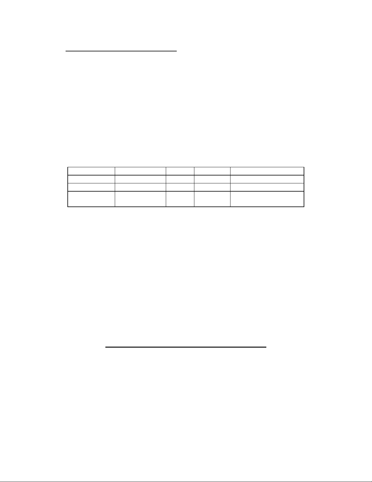
Part # Model # Track # Functional Description
7A07000
7
7A070005 MR-
7A070011 MR-
Interfacing to the Magnetic Card Reader
This section details the software steps required to access the Magnetic Card Reader from a
computer or from a terminal.
Select the MSP/MPP printer
The Host Selects the MSP/MPP printer by activating the RTS input line or
sending wake-up character to the printer.
The Printer Sends the XON command to the Host to indicate ready to receive
Command strings. The host has to wait for XON before proceeding.
MR2105
1102
2106
1 & 2 Track 1 - 79 characters / 7 bit
2 Track 2 - 40 characters / 7 bit
2 & 3 Track 2 - 40 characters / 7 bit
Note: All readers will accept odd or even Parity
Track # - Max. capacity/ data bits
Recording method/Recording Density
RecM: F2F : RecD:210BPI
Track 2 - 40 characters / 5 bit
RecM: FM : RecD: 75BPI
RecM: FM : RecD: 75BPI
RecM: FM RecD: 75BPI
Track 3 - 107 characters / 5 bit
RecM: F2F RecD:210BPI
Table 1
Page 28
Page 28

Select the Magnetic Card Reader
The Host sends ASCII serial command string to enable the Magnetic Card
Reader. The printer turns on the <READY> LED if the proper command string is
received.
Receive the ASCII Data Output from printer
Once the magnetic card is swiped by the operator, the printer transmits in ASCII
format <Track Data> or <Error Message>. A good read automatically turns off
the reader. The printer turns on the red <ERROR> LED if an error is
encountered.
Magnetic Card Command String Description
ESC - M - nn - 1 - CR Read Track1 only
ESC - M - nn - 2 - CR Read Track2 only
ESC - M - nn - 3 - CR Read Track3 only
ESC - M - nn - 4 - CR Read Track1 and Track2 simultaneously
ESC - M - nn - 5 - CR Read Track2 and Track3 simultaneously
ESC – C Cancel Read
Turns off the <READY> LED
Table 2
(nn = ASCII "01" through "99" seconds)
Recognized Magnetic Card command strings
Six Magnetic Card command strings are recognized by the printer, these commands are
summarized in Table 2.
The command syntax is as follows:
ESC M n n Track # CR
(1) ( 2 ) (3) (4)
(1) Turn On the Card Reader
The first two characters "ESC" and "M" will turn on the Card Reader.
(2) Set the Card Read Timeout
The next two digits "01" through "99" sets the timeout in seconds before the
printer turns off the Card Reader. A good read automatically turns off the
reader.
(3) Select Track number to read
The Fifth character specifies the Track number(s) to read.
Sending "1", "2" or "3" enables read of single track 1, 2 or 3.
Sending "4" enables simultaneous read of tracks 1 and 2.
Sending "5" enables simultaneous read of tracks 2 and 3.
There is no command to read tracks 1, 2 and 3 simultaneously.
Page 29
Page 29

(4) Terminate command string
The MSP/MMP waits for Carriage return character before start of the Magnetic
card read process.
Table 2 summarizes the recognized Magnetic card command strings.
Track Data Output Format
The <Track Data> retrieved from magnetic card is transmitted to the Host in ASCII format. The
<Track Data> format is as follows:
/1/ <TRACK 1 DATA> <CR> <LF>
/2/ <TRACK 2 DATA> <CR> <LF>
/3/ <TRACK 3 DATA> <CR> <LF>
The first three characters (/,1,/) flag the track number. The track data follows the third
character, CR-LF terminates the <Track Data> string.
Read Error Messages
All error messages are prefaced by <ESC><E> characters. Following these two characters is a
comma, the error number in ASCII (01 through 99), another comma, English description of the
error encountered and finally CR-LF terminating the <Error Message> string. The syntax is as
follows:
<ESC><E>, nn, Error text in ASCII, <CR><LF>
Where nn is error number encountered. Nine (9) types of Read Error messages may be
transmitted by the Mag card reader. The following messages terminated with CR-LF are
returned by the firmware:
Error # Error Message Transmitted
01 Parity Error
02 Checksum Error
03 End Sentinel Not Found
04 Too Many Characters
05 Timeout Expired
06 Invalid Character
07 Invalid Track Number
08 Unsupported Track Selected
09 Cancel Request
Page 30
Page 30

Read Error Messages description
Error # Error Message Description
01 The Parity of the character read is opposite of the
card default parity.
02 The Checksum calculated did not match the one on the
card. The checksum is calculated by Exclusive-
OR' ing all the valid data on the card including Begin Sentinel and
End Sentinel, but excluding the checksum byte.
03 End Sentinel must exist on all cards, Reader did not
find the End Sentinel.
04 The Maximum number of characters allowed for a track
was exceeded. This may happen if End Sentinel is not
found. Refer to Table 1 for further details.
05 The command timeout has expired.
06 The Track Reader Escape command string transmitted
by Host contained an invalid character.
07 Invalid Track Number is selected. Tracks "1", "2" or
"3" can be selected.
08 Unsupported Track is Selected. Tracks "1", "2" or
"3" can be selected.
09 "Cancel Request" error string is transmitted if Host
cancels Magnetic card read in process.
Page 31
Page 31

Sample Interface Program in C
#include <stdio.h> // MSC Standard I/O
#include <com.h> // C Run-Time Interrupt Driven Comm
#include <vdsp.h> // C Run-Time Video Display Functions
#define PRINTSPECS CM_SERIALFSM | CM_9600BAUD | CM_NOPRTY |
CM_8BITS| CM_1STOP
void readtrk( int );
void exit( void );
char buf[80]; // Rcv'd data buffer.
char *cp = buf; // Next buffer loc to use.
void main( void)
{
int i, status;
/**** Enable Printer ****/
if ((status = comopen( COM1, PRINTSPECS, "", CS_NODSP)) !=NOERR)
exit();
/**** SELECT XON communication ****/
comxoff( COM1, YES);
/**** Read Tracks ****/
readtrk( 1 );
readtrk( 2 );
readtrk( 3 );
comclose( COM1, CS_NODSP);
}
void readtrk( int tn )
{
char cmd[12];
cp = buf;
vdspls( 4, 11, "Req track read ");
sprintf( cmd, "%cM%02d%1d\r", 27, TIMEOUT, tn); /* read Track */
vdspls( 4, 11, "Read track %d ", tn); /* display */
}
Page 32
Page 32

Appendix D
Infrared Data Input Option
Introduction
This appendix summarizes the operating features of the Extech MSP Series printers with built in
InfraRed Data Receiver Interface (IRD). The IRD Interface is designed for reception of IRDASK format serial data and no interconnecting cables are required for data transfer.
The IRD data transfer is a one way link, in the current version of the printers. The printer has
circuitry to receive IRD-ASK data but there is no circuit allowing IRD to be transmitted back.
For reliable serial data transfer, software timing must be implemented in the IRD-ASK
transmitter. It is the transmitters responsibility to be sure the printer's 2000 Byte buffer never
overflows.
IRD-ASK Receiver Specification
The IRD-ASK receiver consists of photodiode IR detector, automatic gain control amplifier and
500KHZ bandpass filter.
The amplifier prevents saturation of the receiver if strong IR signal is applied, while the
bandpass filter rejects any IR signal without the 500KHZ carrier signal.
The Operating Characteristics of IR Receiver are summarized in TABLE 1.
Transmission Wavelength 900 to 1,050 nanometers
Modulation Frequency 500KHZ ± 50
Modulation Process Amplitude Shift Key (ASK)
Range 1 meter
Data Rate 1200 - 9,600 Bits per second/
DIP switch select baud rate and
parity.
Table 1
IR Receiver Operating Characteristic
Printer Power-up through IRD-ASK Interface
The MSP printer can be powered-up by transmitting a single character. To avoid the loss of data
during "Logic Switching", pause for 1.0 seconds before sending additional characters to the
printer.
The MSP printers have a built-in 30 second Power-Down-Timer. The timer is automatically
restarted under any one of the following conditions.
- If side panel <ON>, <FEED> or <ADVN> switch is pressed.
- If a character is received via IRD-ASK data interface.
Page 33
Page 33

Upon timeout of the Power-Down-Timer, the printer starts flashing the red <Error> LED to warn
the operator, before turning power off.
Serial Baud Rate and Parity
Since IRD-ASK data transfer is serial, The proper Baud Rate and parity settings are required to
communicate with a Host computer.
Refer to MSP User's manual to set the desired baud rate and parity.
Software Interface Overview
This section details the software steps required for reliable serial IRD-ASK data transfer,
STEP 1 Select the Printer
The Host Selects the MSP printer by sending wake-up character to the printer.
To avoid the loss of data during printer select process, the Host pauses for 1.0
seconds before sending additional characters to the printer.
STEP 2 Initialize the Printer
The MSP User's Manual list the printer operating modes such as character set,
character width and height and graphics mode. These are all set to their default
state on printer power up.
To Initialize the Printer, the Host sends ASCII serial command string to enable
the desired operating mode.
STEP 3 Transmit the ASCII Data to printer
Since the IRD-ASK data transfer is in one direction, from Host to the printer, it is
the Host responsibility to be sure the printer's 2000 Byte buffer never
overflows.
The following simple timing technique can be implemented in the IRD-ASK
transmitter.
- Treat every line to be printed as a complete line, independent of the
number of characters on that line.
- Keep track of the number of lines sent.
- Before sending a line, check to see if print buffer is
full.
(50 lines for 24 column printers)
(28 lines for 40/42 column printer).
- If print buffer is full, Wait 2 seconds before sending the next line.
Page 34
Page 34

Figure 1.0
Showing front labels (including charge indicators) and model number
Page 35
Page 35

Figure 1.1
Membrane Switch panel showing <SLCT>, <FEED>, <SET> and <ADVN> switches.
Page 36
Page 36

Figure 1.3
Battery compartment view showing battery pack, polarity and part number
Page 37
Page 37

Figure 1.4
Showing Paper Roll installation
Page 38
Page 38

Figure 1.5
Showing Ribbon Cartridge
Page 39
Page 39

Figure 1.6
Performing Power-Up and Self-Test
Page 40
Page 40

Figure 3.1
Showing Dip switch location
Page 41
Page 41

Figure 2.2
parallel interface timing
Page 42
 Loading...