

Page 1
User's Guide
600Amp AC True RMS Clamp Meter
Model MA620
Find Quality Products Online at: sales@GlobalTestSupply.com
www.GlobalTestSupply.com
Page 2

Introduction
Congratulations on your purchase of this Extech MA640 True RMS Clamp Meter. This meter
measures AC Current, AC/DC Voltage, Resistance, Capacitance, Frequency, Diode Test,
Duty Cycle and Continuity. Special features include Thermocouple Temperature and NonContact Voltage detection. The double molded case is designed for heavy duty use. This
meter is shipped fully tested and calibrated and, with proper use, will provide years of reliable
service.
Safety
International Safety Symbols
This symbol, adjacent to another symbol or terminal, indicates the user
must refer to the manual for further information.
This symbol, adjacent to a terminal, indicates that, under normal use,
hazardous voltages may be present
Double insulation
WARNING
CAUTION
PER IEC1010 OVERVOLTAGE INSTALLATION CATEGORY
OVERVOLTAGE CATEGORY I
Equipment of OVERVOLTAGE CATEGORY I is equipment for connection to circuits in
which measures are taken to limit the transient overvoltages to an appropriate low level.
Note – Examples include protected electronic circuits.
OVERVOLTAGE CATEGORY II
Equipment of OVERVOLTAGE CATEGORY II is energy-consuming equipment to be
supplied from the fixed installation.
Note – Examples include household, office, and laboratory appliances.
OVERVOLTAGE CATEGORY III
Equipment of OVERVOLTAGE CATEGORY III is equipment in fixed installations.
Note – Examples include switches in the fixed installation and some equipment for industrial
use with permanent connection to the fixed installation.
OVERVOLTAGE CATEGORY IV
Equipment of OVERVOLTAGE CATEGORY IV is for use at the origin of the installation.
Note – Examples include electricity meters and primary over-current protection equipment
This WARNING symbol indicates a potentially hazardous situation, which
if not avoided, could result in death or serious injury.
This CAUTION symbol indicates a potentially hazardous situation, which
if not avoided, may result damage to the product.
2
Find Quality Products Online at: sales@GlobalTestSupply.com
www.GlobalTestSupply.com
MA620 V2.1 07/08
Page 3

SAFETY NOTES
• Do not exceed the maximum allowable input range of any function.
• Do not apply voltage to meter when resistance function is selected.
• Set the function switch OFF when the meter is not in use.
• Remove the battery if meter is to be stored for longer than 60 days.
WARNINGS
• Set function switch to the appropriate position before measuring.
• When measuring volts do not switch to current/resistance modes.
• Do not measure current on a circuit whose voltage exceeds 600V.
• When changing ranges always disconnect the test leads from the circuit under test.
CAUTIONS
• Improper use of this meter can cause damage, shock, injury or death. Read and
understand this user manual before operating the meter.
• Always remove the test leads before replacing the battery or fuses.
• Inspect the condition of the test leads and the meter itself for any damage before
operating the meter. Repair or replace any damage before use.
• Use great care when making measurements if the voltages are greater than 25VAC
rms or 35VDC. These voltages are considered a shock hazard.
• Always discharge capacitors and remove power from the device under test before
performing Diode, Resistance or Continuity tests.
• Voltage checks on electrical outlets can be difficult and misleading because of the
uncertainty of connection to the recessed electrical contacts. Other means should be
used to ensure that the terminals are not "live".
• If the equipment is used in a manner not specified by the manufacturer, the protection
provided by the equipment may be impaired.
Function Maximum Input
A AC 600A DC/AC
V DC, V AC 600V DC/AC
Resistance, Capacitance, Frequency, Diode Test 250V DC/AC
Type K Temperature 30V DC, 24V AC
250V DC/AC
3
Find Quality Products Online at: sales@GlobalTestSupply.com
www.GlobalTestSupply.com
MA620 V2.1 07/08
Page 4

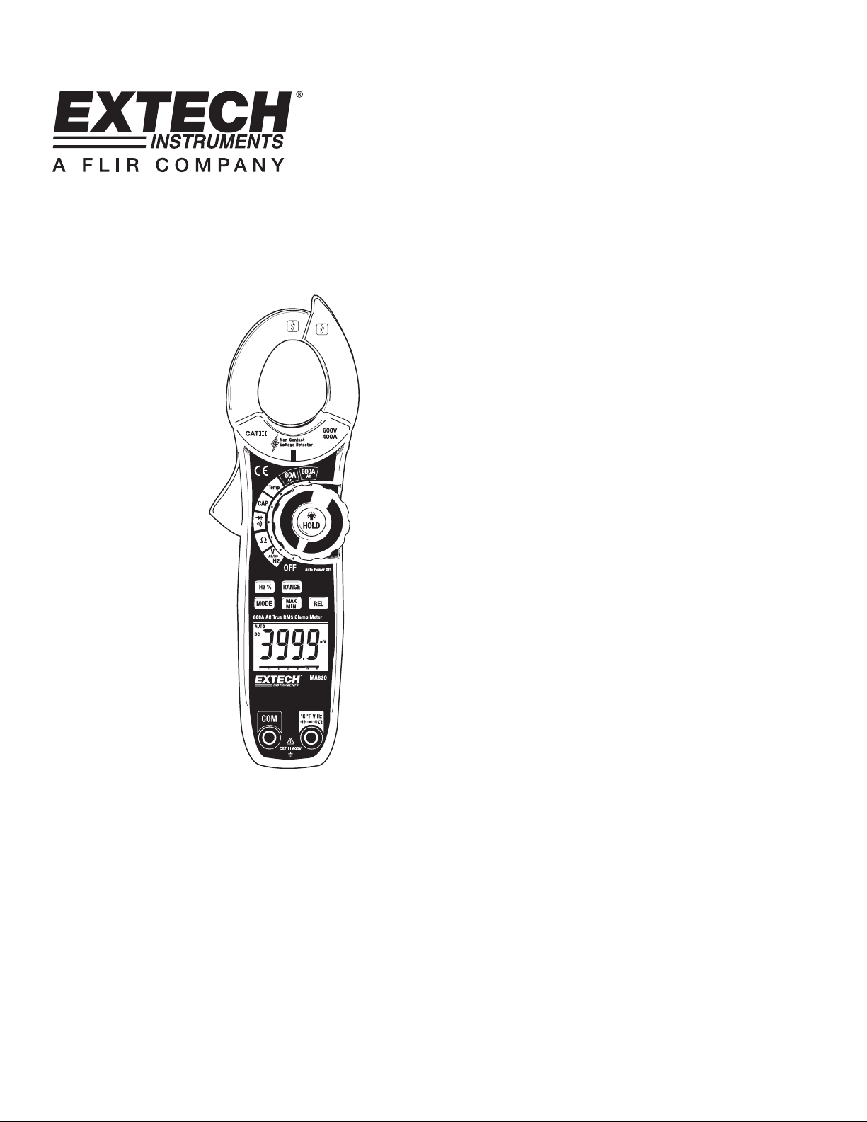
Description
Meter Description
1. Current clamp
2. Clamp opening trigger
3. Hx % Button
4. MODE Button
5. LCD Display
6. Common Input jack
7. NCV sensor
8. NCV LED indicator
9. HOLD/BACKLIGHT Button and FUNCTION switch
10. RANGE Button
11. MAX-MIN Button
12. RELATIVE Button
13. Battery compartment (rear)
14. Positive Input jack
Display icons Description
HOLD Data Hold
AUTO Autoranging
DC Direct Current
AC Alternating Current
MAX Max reading
MIN Min reading
Low battery
REL Relative
V Volts (Voltage)
Ω Ohms (Resistance)
A Amperes (Current)
F Farad (Capacitance)
Hz Hertz (Frequency)
% Duty Ratio
o
F and oC Fahrenheit and Celsius units (Temperature)
n, m, μ, M, k Unit of measure prefixes: nano, milli, micro, mega, and kilo
)
)
•
) Continuity test
Diode test
4
Find Quality Products Online at: sales@GlobalTestSupply.com
www.GlobalTestSupply.com
MA620 V2.1 07/08
Page 5

Operation
NOTES: Read and understand all Warning and Caution statements in this operation
manual prior to using this meter. Set the function select switch to the OFF position when
the meter is not in use.
Non-Contact Voltage Detector
WARNING: Risk of Electrocution. Before use, always test the Voltage Detector on a
1. Rotate the Function switch to any measurement
2. Place the detector probe tip on the conductor to be
3. If AC voltage is present, the NCV detector light will
NOTE: The conductors in electrical cord sets are often
NOTE: The detector is designed with high sensitivity. Static electricity or other sources of
AC Current Measurements
WARNING: Disconnect the test leads before making clamp measurements.
1. Rotate the Function switch to the
2. Press the trigger to open jaw. Fully
3. Read the current value in the display.
4. If the value is less than 60A, rotate
known live circuit to verify proper operation.
position.
tested.
turn on with a steady red light.
twisted. For best results, move the probe tip along
a length of the cord to assure placing the tip in close proximity to the live conductor.
energy may randomly trip the sensor. This is normal operation.
600A AC position
enclose only one conductor.
the function switch to the 60A position
to improve resolution.
5
Find Quality Products Online at: sales@GlobalTestSupply.com
www.GlobalTestSupply.com
MA620 V2.1 07/08
Page 6

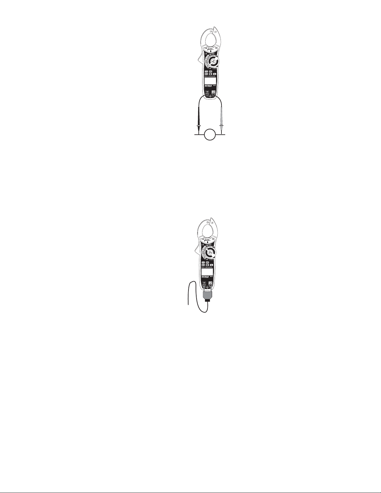
AC/DC Voltage Measurements
CAUTION: Do not measure voltages if a motor on the circuit is being switched ON or
OFF. Large voltage surges may occur that can damage the meter.
1. Rotate the function switch to the V position.
2. Press the MODE button to select AC or DC Voltage.
3. Insert the black test lead banana plug into the negative COM jack.
Insert the red test lead banana plug into the positive V jack.
4. Touch the black test probe tip to the negative side of the circuit.
Touch the red test probe tip to the positive side of the circuit.
5. Read the voltage value in the display.
Resistance Measurements
Note: Remove power from the device under test before making resistance measurements
1. Rotate the function switch to the Ω position.
2. Insert the black test lead banana plug into the negative COM jack.
Insert the red test lead banana plug into the positive V jack.
3. Touch the black test probe tip to one side of the device.
Touch the red test probe tip to the other side of the device.
4. Read the resistance value in the display.
6
Find Quality Products Online at: sales@GlobalTestSupply.com
www.GlobalTestSupply.com
MA620 V2.1 07/08
Page 7

Continuity Test
)
1. Rotate the function switch to the •
)
) position.
2. Insert the black test lead banana plug into the negative COM jack.
Insert the red test lead banana plug into the positive V jack.
)
)
•
3. Press the MODE button to select continuity
).
4. Touch the black test probe tip to one side of the device.
Touch the red test probe tip to the other side of the device..
5. Touch the test probe tips across the circuit or component under test.
6. If the resistance is < 60Ω, a tone will sound.
Diode Test
1. Rotate the function switch to the position.
2. Insert the black test lead banana plug into the negative COM jack.
Insert the red test lead banana plug into the positive V jack
3. Press the MODE button to select diode test .
4. Touch the test probe tips to the diode or semiconductor junction under test. Note the
meter reading.
5. Reverse the test lead polarity by reversing the red and black leads. Note this reading.
6. The diode or junction can be evaluated as follows:
If one reading displays a value (typically 0.400V to 01.800V) and the other
reading displays OL, the diode is good.
If both readings display OL the device is open.
If both readings are very small or ‘0’, the device is shorted.
Capacitance Measurements
WARNING: To avoid electric shock, discharge the capacitor before measuring.
1. Rotate the function switch to the CAP position.
2. Insert the black test lead banana plug into the negative COM jack.
Insert the red test lead banana plug into the positive
3. Touch the black test probe tip to one side of the device.
Touch the red test probe tip to the other side of the device.
4. Read the capacitance value in the display.
Note: For very large values of capacitance measurement time can be
several seconds before the final reading stabilizes.
7
jack.
MA620 V2.1 07/08
Find Quality Products Online at: sales@GlobalTestSupply.com
www.GlobalTestSupply.com
Page 8
Frequency and Duty Ratio Measurements
1. Rotate the function switch to the Hz Position.
2. Press the MODE button to select AC Voltage
3. Press the HZ % button to select HZ
4. Insert the black test lead banana plug into the negative COM jack.
Insert the red test lead banana plug into the positive Hz jack.
5. Touch the black test probe tip to one side of the device.
Touch the red test probe tip to the other side of the device.
6. Read the Frequency value on the display.
7. Press the HZ % button to select %
8. Read the Duty Ratio on the display.
Type K Temperature Measurements
1. Rotate the function switch to the Temp position.
2. Press the MODE button to select °F or °C.
3. Insert the Temperature Probe into the input jacks.
4. Place the temperature probe tip where needed.
5. Read the temperature on the display.
Note: In case of an open input or a temperature overrange, the meter
will display “OL”.
HZ
8
Find Quality Products Online at: sales@GlobalTestSupply.com
www.GlobalTestSupply.com
MA620 V2.1 07/08
Page 9

Data Hold
To freeze the LCD reading, press the HOLD button. While data hold is active, the HOLD
icon appears on the LCD. Press the HOLD button again to return to normal operation.
MAX/MIN
1. Press the MAX/MIN button to activate the MAX/MIN recording mode. The display icon
"MAX" will appear. The meter will begins recording and displaying the maximum
value measured.
2. Press the MAX/MIN button and “MIN” will appear. The meter will display the minimum
value measured during the recording session.
3. To exit MAX/MIN mode press and hold the MAX/MIN button for 2 seconds.
RANGE
In the Voltage, Resistance, Frequency or Temperature function the meter automatically
selects the best range for the measurements being made. For measurement situations
requiring that a range be manually selected, perform the following:
1. Press the RANGE button. The “AUTO” display icon will turn off.
2. Press the RANGE key to step through the available ranges. Observe the decimal
point and units displayed until the preferred range is located.
3. To exit the Manual Ranging mode and return to Autoranging, press and hold the
RANGE key for 2 seconds.
LCD Backlight
The LCD is equipped with backlighting for easier viewing, especially in dimly lit areas.
Press and hold the HOLD/
will automatically turn off after 5 seconds.
button for 2 seconds to turn the backlight on. The backlight
Automatic Power OFF
In order to conserve battery life, the meter will automatically turn off after approximately 15
minutes of operation. The meter will beep shortly before the meter shuts off. If a button is
pressed, the APO timer will reset. If the meter is allowed to shut off, turn the function
switch to the OFF position and then to the function again to restart.
Low battery indication
When the icon appears in the display, the battery should be replaced. Refer to the
battery replacement procedure in the maintenance section.
9
MA620 V2.1 07/08
Find Quality Products Online at: sales@GlobalTestSupply.com
www.GlobalTestSupply.com
Page 10

Maintenance
WARNING: To avoid electrical shock, disconnect the meter from any circuit, remove the
test leads from the input terminals, and turn OFF the meter before opening the case. Do
not operate the meter with an open case.
Cleaning and Storage
Periodically wipe the case with a damp cloth and mild detergent; do not use abrasives or
solvents. If the meter is not to be used for 60 days or more, remove the battery and store it
separately.
Battery Replacement
1. Remove the Phillips head screws that secures the rear battery door
2. Open the battery compartment
3. Replace the 9V battery
4. Secure the battery compartment door
Warranty
EXTECH INSTRUMENTS CORPORATION(a FLIR company) warrants this instrument to be free
of defects in parts and workmanship for one year from date of shipment (a six month limited
warranty applies to sensors and cables). If it should bec ome neces sary to return t he i nstrument f or
service during or beyond the warranty per iod, contact the Customer Serv ice Department at (781)
890-7440 ext. 210 for authorization or visit our website www.extech.com for contact information. A
Return Authorization (RA) number must be issued before any product is returned to Extech. The
sender is responsible for shipping charges, freight, i nsurance and proper packaging to prevent
damage in transit. This warranty does not apply to defects resulting from action of the user such as
misuse, improper wiring, operation outside of specification, improper maintenance or repair, or
unauthorized modification. Extech spec ifically disclaims any implie d warranties or merchantability
or fitness for a specific purpose and will not be liable for any direct, indirect, incidental or
consequential damages. Extech's t otal liability is limited to repair or replacem ent of the product.
The warranty set forth above is inclusive and no other warranty, whether written or oral, is
expressed or implied.
Calibration and Repair Services
Extech offers repair and calibration services for the products we sell. Extech also
provides NIST certification for most products. Call the Customer Care Department for
information on calibration services available for this product. Extech recommends that
annual calibrations be performed to verify meter performance and accuracy.
10
MA620 V2.1 07/08
Find Quality Products Online at: sales@GlobalTestSupply.com
www.GlobalTestSupply.com
Page 11
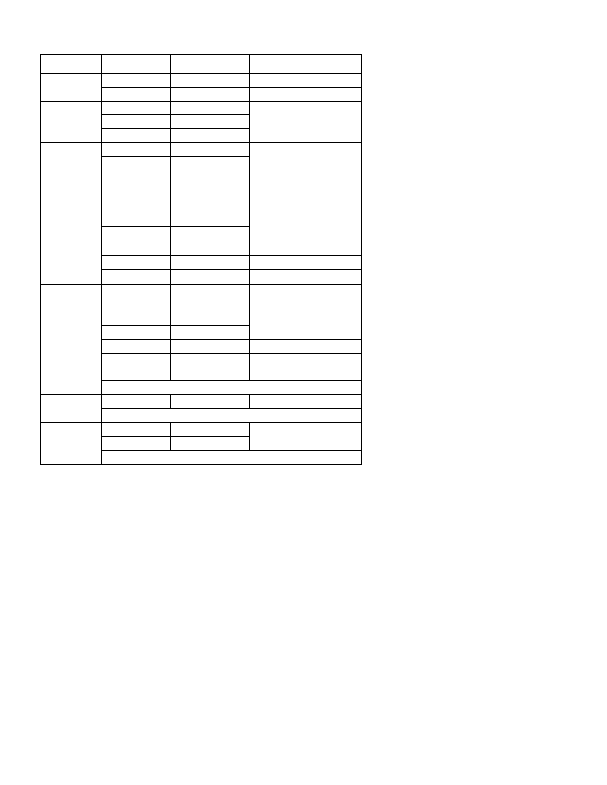
Specifications
Function Range Resolution
50/60 Hz
True RMS
AC Voltage
True RMS
DC Voltage
Resistance
Capacitance
Temperature
Type K
60.00 AAC 0.01A ±(2.8% + 8 digits) AC Current
600.0 AAC 0.1A ±(3.0% + 8 digits)
6.000 VAC 0.001V
60.00 VAC 0.01V
600.0 VAC 0.1V
600.0 mVDC 0.1mV
6.000 VDC 0.001V
60.00 VDC 0.01V
600.0 VDC 0.1V
600.0Ω 0.1Ω
6.000kΩ 0.001kΩ
60.00kΩ 0.01kΩ
600.0kΩ 0.1kΩ
6.000MΩ 0.001MΩ
60.00MΩ 0.01MΩ
40.00nF 0.01nF ±(4.0% + 20 digits)
400.0nF 0.1nF
4.000µF 0.001µF
40.00µF 0.01µF
400.0µF 0.1µF ±(4.0% + 10 digits)
4000µF 1µF ±(5.0% + 10 digits)
10Hz to 10kHz 0.01Hz to 0.01khz ±(1.5% + 2 digits) Frequency
Sensitivity: 15Vrms
0.5% to 99.0% 0.1% ±(1.2% + 2 digits) Duty Cycle
Pulse width: 100μs to 100ms, Frequency: 10Hz to 10kHz
-4 to - 1400°F 0.1° <800°; 1° >800°
-20 to 760°C 0.1° <400°; 1° >400°
Specification does not include probe accuracy
Accuracy
(% of reading + digits)
±(1.8% + 8 digits)
±(1.5% + 2 digits)
±(1.0% + 4 digits)
±(1.5% + 2 digits)
±(2.5% + 3 digits)
±(3.5% + 5 digits)
±(3.0% + 5 digits)
±3% reading + 9°F/5°C
11
Find Quality Products Online at: sales@GlobalTestSupply.com
www.GlobalTestSupply.com
MA620 V2.1 07/08
Page 12

Genera
l Specifications
Clamp jaw opening 1.5" (40mm) approx.
Display 6000 count backlit LCD
Continuity check Threshold 60Ω; Test current < 0.35mA
Diode test Test current of 0.9mA typical;
Open circuit voltage [ 2.8VDC typical
Low Battery indication Battery symbol is displayed
Over-range indication ‘OL’ display
Measurement rate 2 readings per second, nominal
Thermocouple sensor Type K thermocouple required
Input Impedance 10MΩ (VDC and VAC)
AC current bandwidth 50/60Hz
AC voltage bandwidth 50 to 400Hz
AC response True rms (AAC and VAC)
Crest Factor 3.0 in 60A and 600A ranges, (50/60Hz and 5% to 100% of
Operating Temperature 41°F to 104°F (5°C to 40°C)
Storage Temperature -4°F to 140°F (-20°C to 60°C)
Operating Humidity Max 80% up to 87°F (31°C) decreasing linearly to 50% at
Storage Humidity <80%
Operating Altitude 7000ft. (2000meters) maximum.
Battery One (1) 9V Battery (NEDA 1604)
Auto power OFF After approx. 15 minutes, with disable
Dimensions & Weight 9.2x3 x1.53” (232x77x39mm); 9.56 oz. (271g)
Safety For indoor use and in accordance with the requirements for
Approvals CE,
range)
104°F(40°C)
double insulation to IEC1010-1 (2001): EN61010-1 (2001)
Overvoltage Category III 600V and Category II 1000V,
Pollution Degree 2.
12
Find Quality Products Online at: sales@GlobalTestSupply.com
www.GlobalTestSupply.com
MA620 V2.1 07/08
 Loading...